


User Manual
POINT Guard I/O Safety Modules
Catalog Numbers 1734-IB8S, 1734-OB8S, 1734-IE4S
Important User Information
IMPORTANT
Read this document and the documents listed in the additional resources section about installation, configuration, and
operation of this equipment before you install, configure, operate, or maintain this product. Users are required to
familiarize themselves with installation and wiring instructions in addition to requirements of all applicable codes, laws,
and standards.
Activities including installation, adjustments, putting into service, use, assembly, disassembly, and maintenance are required
to be carried out by suitably trained personnel in accordance with applicable code of practice.
If this equipment is used in a manner not specified by the manufacturer, the protection provided by the equipment may be
impaired.
In no event will Rockwell Automation, Inc. be responsible or liable for indirect or consequential damages resulting from the
use or application of this equipment.
The examples and diagrams in this manual are included solely for illustrative purposes. Because of the many variables and
requirements associated with any particular installation, Rockwell Automation, Inc. cannot assume responsibility or
liability for actual use based on the examples and diagrams.
No patent liability is assumed by Rockwell Automation, Inc. with respect to use of information, circuits, equipment, or
software described in this manual.
Reproduction of the contents of this manual, in whole or in part, without written permission of Rockwell Automation,
Inc., is prohibited.
Throughout this manual, when necessary, we use notes to make you aware of safety considerations.
WARNING: Identifies information about practices or circumstances that can cause an explosion in a hazardous environment,
which may lead to personal injury or death, property damage, or economic loss.
ATTENTION: Identifies information about practices or circumstances that can lead to personal injury or death, property
damage, or economic loss. Attentions help you identify a hazard, avoid a hazard, and recognize the consequence.
Identifies information that is critical for successful application and understanding of the product.
Labels may also be on or inside the equipment to provide specific precautions.
SHOCK HAZARD: Labels may be on or inside the equipment, for example, a drive or motor, to alert people that dangerous
voltage may be present.
BURN HAZARD: Labels may be on or inside the equipment, for example, a drive or motor, to alert people that surfaces may
reach dangerous temperatures.
ARC FLASH HAZARD: Labels may be on or inside the equipment, for example, a motor control center, to alert people to
potential Arc Flash. Arc Flash will cause severe injury or death. Wear proper Personal Protective Equipment (PPE). Follow ALL
Regulatory requirements for safe work practices and for Personal Protective Equipment (PPE).
Allen-Bradley, GuardLogix, Guardmaster, POINT Guard I/O, Rockwell Automation, Rockwell Software, RSNetWorx, SmartGuard, and Studio 5000 are trademarks of Ro ckwell Automation, Inc.
Trademarks not belonging to Rockwell Automation are property of their respective companies.

Summary of Changes
This manual contains new and updated information. Changes throughout this
revision are marked by change bars, as shown to the right of this paragraph.
New and Updated Information
This table contains the changes made to this revision.
Top ic Pa ge
Added information on accessing Release Notes. 12
Added information on single -channel operation to the list of 1734-IB8S module features 18
Updated Single-channel Mode Normal Operation and Fault Detection figure. 26
Updated Dual-channel, Equivalent Normal Operation and Fault Detection figure. 28
Updated Complementary, Normal Operation and Fault Detection figure. 29
Updated Dual-channel Setting figure. 39
Added information on placing Series B modules. 48
Updated European Hazardous Location Approval information. 52
Added guidance for using the 1734-IE4S module's sensor power supply. 58
Correc ted the Cla ss ID in Ta bl e 15
Updated Appendix C: Specifications 161
Added specification for Sensor Supply Undercurrent Fault. 166
Added Safety Data for Series B modules to Appendix C. 173
Safety Analog Input Module (1734-IE4S) 158
Rockwell Automation Publication 1734-UM013J-EN-P - July 2014 3

Summary of Changes
Notes:
4 Rockwell Automation Publication 1734-UM013J-EN-P - July 2014

POINT Guard I/O Overview
Table of Contents
Preface
Studio 5000 Environment . . . . . . . . . . . . . . . . . . . . . . . . . . . . . . . . . . . . . . . . 11
Terminology. . . . . . . . . . . . . . . . . . . . . . . . . . . . . . . . . . . . . . . . . . . . . . . . . . . . . 12
Access Product Release Notes . . . . . . . . . . . . . . . . . . . . . . . . . . . . . . . . . . . . . 12
Additional Resources . . . . . . . . . . . . . . . . . . . . . . . . . . . . . . . . . . . . . . . . . . . . . 13
Chapter 1
Understand Suitability for Use . . . . . . . . . . . . . . . . . . . . . . . . . . . . . . . . . . . . 15
Safety Precautions. . . . . . . . . . . . . . . . . . . . . . . . . . . . . . . . . . . . . . . . . . . . . . . . 17
Installing and Replacing Modules . . . . . . . . . . . . . . . . . . . . . . . . . . . . . . 17
POINT Guard I/O Modules in CIP Safety Systems. . . . . . . . . . . . . . . . . 17
1734-IB8S Digital Input Module Features. . . . . . . . . . . . . . . . . . . . . . 18
1734-OB8S Safety Digital Output Module Features. . . . . . . . . . . . . 18
1734-IE4S Safety Analog Input Module Features . . . . . . . . . . . . . . . 19
Programming Requirements. . . . . . . . . . . . . . . . . . . . . . . . . . . . . . . . . . . 19
CIP Safety Architectures . . . . . . . . . . . . . . . . . . . . . . . . . . . . . . . . . . . . . . 20
Safety Application Requirements . . . . . . . . . . . . . . . . . . . . . . . . . . . . . . . . . . 21
Safety Inputs, Safety Outputs, and
Safety Data
Chapter 2
Safe States . . . . . . . . . . . . . . . . . . . . . . . . . . . . . . . . . . . . . . . . . . . . . . . . . . . . . . . 23
POINT Guard Digital I/O Modules . . . . . . . . . . . . . . . . . . . . . . . . . . . 23
POINT Guard I/O Analog Input Module. . . . . . . . . . . . . . . . . . . . . . 24
Safety Inputs (1734-IB8S) . . . . . . . . . . . . . . . . . . . . . . . . . . . . . . . . . . . . . . . . 24
Using a Test Output with a Safety Input . . . . . . . . . . . . . . . . . . . . . . . 24
Single-channel Mode . . . . . . . . . . . . . . . . . . . . . . . . . . . . . . . . . . . . . . . . . 26
Dual-channel Mode and Discrepancy Time. . . . . . . . . . . . . . . . . . . . . 27
Dual-channel, Equivalent . . . . . . . . . . . . . . . . . . . . . . . . . . . . . . . . . . . . . 28
Dual-channels, Complementary . . . . . . . . . . . . . . . . . . . . . . . . . . . . . . . 29
Safety Input Fault Recovery . . . . . . . . . . . . . . . . . . . . . . . . . . . . . . . . . . . 30
Input Delays . . . . . . . . . . . . . . . . . . . . . . . . . . . . . . . . . . . . . . . . . . . . . . . . . 30
Safety Analog Inputs (1734-IE4S) . . . . . . . . . . . . . . . . . . . . . . . . . . . . . . . . . 31
Input Range . . . . . . . . . . . . . . . . . . . . . . . . . . . . . . . . . . . . . . . . . . . . . . . . . 31
Scaling. . . . . . . . . . . . . . . . . . . . . . . . . . . . . . . . . . . . . . . . . . . . . . . . . . . . . . . 31
Digital Input Filter . . . . . . . . . . . . . . . . . . . . . . . . . . . . . . . . . . . . . . . . . . . 32
Sensor Power Supply . . . . . . . . . . . . . . . . . . . . . . . . . . . . . . . . . . . . . . . . . 32
Channel Offset. . . . . . . . . . . . . . . . . . . . . . . . . . . . . . . . . . . . . . . . . . . . . . . 33
Process Alarms . . . . . . . . . . . . . . . . . . . . . . . . . . . . . . . . . . . . . . . . . . . . . . . 33
Using a Single-channel Sensor . . . . . . . . . . . . . . . . . . . . . . . . . . . . . . . . . 34
Dual-channel Equivalent Mode. . . . . . . . . . . . . . . . . . . . . . . . . . . . . . . . 35
Tachometer Mode. . . . . . . . . . . . . . . . . . . . . . . . . . . . . . . . . . . . . . . . . . . . 36
Safety Outputs (1734-OB8S) . . . . . . . . . . . . . . . . . . . . . . . . . . . . . . . . . . . . . 39
Safety Output with Test Pulse . . . . . . . . . . . . . . . . . . . . . . . . . . . . . . . . . 39
Dual-channel Mode . . . . . . . . . . . . . . . . . . . . . . . . . . . . . . . . . . . . . . . . . . 39
Safety Output Fault Recovery . . . . . . . . . . . . . . . . . . . . . . . . . . . . . . . . . 40
Muting Lamp Operation (1734-IB8S) . . . . . . . . . . . . . . . . . . . . . . . . . . . . . 40
Rockwell Automation Publication 1734-UM013J-EN-P - July 2014 5

Table of Contents
Guidelines for Placing Power Supplies
and Modules in a System
Install the Module
I/O Status Data . . . . . . . . . . . . . . . . . . . . . . . . . . . . . . . . . . . . . . . . . . . . . . . . . . 42
Digital I/O Status Data . . . . . . . . . . . . . . . . . . . . . . . . . . . . . . . . . . . . . . . 42
Analog I/O Status Data . . . . . . . . . . . . . . . . . . . . . . . . . . . . . . . . . . . . . . . 43
Chapter 3
Choosing a Power Supply . . . . . . . . . . . . . . . . . . . . . . . . . . . . . . . . . . . . . . . . . 45
Power Supply Examples . . . . . . . . . . . . . . . . . . . . . . . . . . . . . . . . . . . . . . . . . . . 46
Example 1: Isolating Field Power Segments . . . . . . . . . . . . . . . . . . . . . 47
Example 2: POINT Guard I/O Used with AC I/O Modules . . . . . 47
Placing Series A Digital and Analog Modules . . . . . . . . . . . . . . . . . . . . . . . 48
Placing Series B Digital Modules. . . . . . . . . . . . . . . . . . . . . . . . . . . . . . . . . . . 48
Chapter 4
Precautions . . . . . . . . . . . . . . . . . . . . . . . . . . . . . . . . . . . . . . . . . . . . . . . . . . . . . . 52
European Hazardous Location Approval . . . . . . . . . . . . . . . . . . . . . . . 52
North American Hazardous Location Approval. . . . . . . . . . . . . . . . . 53
Environment and Enclosure . . . . . . . . . . . . . . . . . . . . . . . . . . . . . . . . . . . 53
Preventing Electrostatic Discharge . . . . . . . . . . . . . . . . . . . . . . . . . . . . . 54
Mount the Module . . . . . . . . . . . . . . . . . . . . . . . . . . . . . . . . . . . . . . . . . . . . . . . 54
Install the Mounting Base . . . . . . . . . . . . . . . . . . . . . . . . . . . . . . . . . . . . . 54
Connect the Module to the Mounting Base . . . . . . . . . . . . . . . . . . . . . 55
Connect the Removable Terminal Block. . . . . . . . . . . . . . . . . . . . . . . . 56
Remove a Mounting Base. . . . . . . . . . . . . . . . . . . . . . . . . . . . . . . . . . . . . . 57
Wire Modules. . . . . . . . . . . . . . . . . . . . . . . . . . . . . . . . . . . . . . . . . . . . . . . . . . . . 58
Terminal Layout. . . . . . . . . . . . . . . . . . . . . . . . . . . . . . . . . . . . . . . . . . . . . . 59
Connection Details. . . . . . . . . . . . . . . . . . . . . . . . . . . . . . . . . . . . . . . . . . . . . . . 60
Wiring Examples . . . . . . . . . . . . . . . . . . . . . . . . . . . . . . . . . . . . . . . . . . . . . . . . . 62
Emergency Stop Dual-channel Devices . . . . . . . . . . . . . . . . . . . . . . . . . 62
Single-channel Safety Contactor . . . . . . . . . . . . . . . . . . . . . . . . . . . . . . . 63
Dual-channel Safety Contactors . . . . . . . . . . . . . . . . . . . . . . . . . . . . . . . 64
Safety Analog Input Wiring . . . . . . . . . . . . . . . . . . . . . . . . . . . . . . . . . . . 65
Chapter 5
Configure the Module in a GuardLogix
Controller System
6 Rockwell Automation Publication 1734-UM013J-EN-P - July 2014
Setting Up the Module . . . . . . . . . . . . . . . . . . . . . . . . . . . . . . . . . . . . . . . . . . . 73
Add and Configure the Ethernet Bridge Module . . . . . . . . . . . . . . . . . . . . 74
Add and Configure the 1734 Ethernet Adapter . . . . . . . . . . . . . . . . . . . . . 75
Add and Configure Safety Digital Input Modules . . . . . . . . . . . . . . . . . . . 77
Add the Safety Digital Input Module. . . . . . . . . . . . . . . . . . . . . . . . . . . 77
Configure the Safety Digital Inputs . . . . . . . . . . . . . . . . . . . . . . . . . . . . 82
Configure the Test Outputs . . . . . . . . . . . . . . . . . . . . . . . . . . . . . . . . . . . 85
Add and Configure Safety Digital Output Modules . . . . . . . . . . . . . . . . . 86
Add the Safety Digital Output Module . . . . . . . . . . . . . . . . . . . . . . . . . 86
Configure the Safety Digital Outputs. . . . . . . . . . . . . . . . . . . . . . . . . . . 90
Add and Configure Safety Analog Input Modules . . . . . . . . . . . . . . . . . . . 91
Add the Safety Analog Input Module. . . . . . . . . . . . . . . . . . . . . . . . . . . 91
Configure the Safety Analog Input Channel Operation . . . . . . . . . . 94
Configure the Safety Analog Inputs . . . . . . . . . . . . . . . . . . . . . . . . . . . . 95

Table of Contents
Configure Safety Analog Input Alarms (optional) . . . . . . . . . . . . . . . 96
Configure Tachometer Operation . . . . . . . . . . . . . . . . . . . . . . . . . . . . . 98
Values and States of Tags . . . . . . . . . . . . . . . . . . . . . . . . . . . . . . . . . . . . . . . . 100
Configure Safety Connections . . . . . . . . . . . . . . . . . . . . . . . . . . . . . . . . . . . 102
Configuration Ownership . . . . . . . . . . . . . . . . . . . . . . . . . . . . . . . . . . . . . . . 103
Saving and Downloading the Module Configuration. . . . . . . . . . . . . . . 104
Using ControlFLASH Software to Update POINT Guard I/O
Modules. . . . . . . . . . . . . . . . . . . . . . . . . . . . . . . . . . . . . . . . . . . . . . . . . . . . . . . . 104
Chapter 6
Configure the Module for a
SmartGuard Controller
Configuring Safety Connections
between a GuardLogix Controller and
POINT Guard I/O Modules on a
DeviceNet Network
Before You Begin . . . . . . . . . . . . . . . . . . . . . . . . . . . . . . . . . . . . . . . . . . . . . . . 105
Set the Node Address. . . . . . . . . . . . . . . . . . . . . . . . . . . . . . . . . . . . . . . . . . . . 106
Auto-addressing with a 1734-PDN Adapter . . . . . . . . . . . . . . . . . . . . . . . 108
Set Up Your DeviceNet Network . . . . . . . . . . . . . . . . . . . . . . . . . . . . . . . . 109
Configure the POINT Guard I/O Modules . . . . . . . . . . . . . . . . . . . . . . . 110
Configure Digital Safety Inputs and Test Outputs . . . . . . . . . . . . . 110
Configure Digital Safety Outputs . . . . . . . . . . . . . . . . . . . . . . . . . . . . . 113
Configure Safety Analog Inputs . . . . . . . . . . . . . . . . . . . . . . . . . . . . . . 114
Configure the SmartGuard Controller . . . . . . . . . . . . . . . . . . . . . . . . . . . . 119
Set Up the Input and Output Connections . . . . . . . . . . . . . . . . . . . . 119
Complete the Set Up of the SmartGuard Controller . . . . . . . . . . . 123
Save and Download Module Configuration . . . . . . . . . . . . . . . . . . . . . . . 124
Chapter 7
Configure the Module in RSNetWorx for DeviceNet Software . . . . . 125
Add the POINT Guard I/O Module to the Controller Project . . . . . 126
Complete the Safety Configuration. . . . . . . . . . . . . . . . . . . . . . . . . . . . . . . 129
Download the DeviceNet Network Configuration. . . . . . . . . . . . . . . . . 131
Verify Your DeviceNet Safety Configuration . . . . . . . . . . . . . . . . . . . . . . 131
Determine If Devices Can Be Verified. . . . . . . . . . . . . . . . . . . . . . . . . 132
Select Devices to Verify . . . . . . . . . . . . . . . . . . . . . . . . . . . . . . . . . . . . . . 133
Review the Safety Device Verification Reports . . . . . . . . . . . . . . . . . 134
Lock Safety Devices. . . . . . . . . . . . . . . . . . . . . . . . . . . . . . . . . . . . . . . . . . 135
Replacing POINT Guard I/O Modules
Chapter 8
The Safety Network Number . . . . . . . . . . . . . . . . . . . . . . . . . . . . . . . . . . . . 137
Manually Setting the Safety Network Number. . . . . . . . . . . . . . . . . . . . . 138
Resetting a Module to Out-of-box Condition . . . . . . . . . . . . . . . . . . . . . 139
By Using the Logix Designer Application. . . . . . . . . . . . . . . . . . . . . . 139
By Using RSNetWorx for DeviceNet Software . . . . . . . . . . . . . . . . 140
Replacing a Module in a GuardLogix System on an EtherNet/IP
Network . . . . . . . . . . . . . . . . . . . . . . . . . . . . . . . . . . . . . . . . . . . . . . . . . . . . . . . 141
Replacement with ‘Configure Only When No Safety Signature
Exists’ Enabled . . . . . . . . . . . . . . . . . . . . . . . . . . . . . . . . . . . . . . . . . . . . . . 141
Replacement with ‘Configure Always’ Enabled. . . . . . . . . . . . . . . . . 145
Replacing a Module When Using a SmartGuard or GuardLogix
Controller on a DeviceNet Network. . . . . . . . . . . . . . . . . . . . . . . . . . . . . . 147
Rockwell Automation Publication 1734-UM013J-EN-P - July 2014 7

Table of Contents
Appendix A
Indicators
Get I/O Diagnostic Status from
Modules in Logix Systems
Specifications
Module . . . . . . . . . . . . . . . . . . . . . . . . . . . . . . . . . . . . . . . . . . . . . . . . . . . . . . . . 152
Network Status . . . . . . . . . . . . . . . . . . . . . . . . . . . . . . . . . . . . . . . . . . . . . . . . . 152
Configuration Lock . . . . . . . . . . . . . . . . . . . . . . . . . . . . . . . . . . . . . . . . . . . . . 152
Power . . . . . . . . . . . . . . . . . . . . . . . . . . . . . . . . . . . . . . . . . . . . . . . . . . . . . . . . . . 153
1734-IE4S Sensor Power . . . . . . . . . . . . . . . . . . . . . . . . . . . . . . . . . . . . . . . . . 153
1734-IE4S Safety Analog Input Status . . . . . . . . . . . . . . . . . . . . . . . . . . . . 153
1734-IB8S Safety Input Status. . . . . . . . . . . . . . . . . . . . . . . . . . . . . . . . . . . . 153
1734-OB8S Safety Output Status. . . . . . . . . . . . . . . . . . . . . . . . . . . . . . . . . 154
Appendix B
Message Instructions. . . . . . . . . . . . . . . . . . . . . . . . . . . . . . . . . . . . . . . . . . . . . 155
Configure the Message Instruction. . . . . . . . . . . . . . . . . . . . . . . . . . . . . . . . 156
Class, Instance, and Attribute Data for I/O Modules . . . . . . . . . . . . . . . 157
Appendix C
Technical Specifications for Series A Modules . . . . . . . . . . . . . . . . . . . . . 161
Safety Digital Input Module Specifications. . . . . . . . . . . . . . . . . . . . . 161
Safety Digital Output Module Specifications. . . . . . . . . . . . . . . . . . . 163
Safety Analog Input Module Specifications . . . . . . . . . . . . . . . . . . . . 164
Technical Specifications for Series B Modules. . . . . . . . . . . . . . . . . . . . . . 173
Safety Digital Input Module Specifications. . . . . . . . . . . . . . . . . . . . . 173
Safety Digital Output Module Specifications. . . . . . . . . . . . . . . . . . . 176
Environmental Specifications. . . . . . . . . . . . . . . . . . . . . . . . . . . . . . . . . . . . . 177
Certifications . . . . . . . . . . . . . . . . . . . . . . . . . . . . . . . . . . . . . . . . . . . . . . . . . . . 179
Legislations and Standards . . . . . . . . . . . . . . . . . . . . . . . . . . . . . . . . . . . . . . . 179
Safety Data
Configuration Parameters
I/O Assemblies
Appendix D
. . . . . . . . . . . . . . . . . . . . . . . . . . . . . . . . . . . . . . . . . . . . . . . . . . . . . . . . . . . . . . . . 181
Series A Safety Data . . . . . . . . . . . . . . . . . . . . . . . . . . . . . . . . . . . . . . . . . . . . . 182
Series B Safety Data. . . . . . . . . . . . . . . . . . . . . . . . . . . . . . . . . . . . . . . . . . . . . . 184
Appendix E
. . . . . . . . . . . . . . . . . . . . . . . . . . . . . . . . . . . . . . . . . . . . . . . . . . . . . . . . . . . . . . . . 187
Appendix F
Input Assemblies . . . . . . . . . . . . . . . . . . . . . . . . . . . . . . . . . . . . . . . . . . . . . . . . 191
Output Assemblies . . . . . . . . . . . . . . . . . . . . . . . . . . . . . . . . . . . . . . . . . . . . . . 192
Analog Input Assemblies. . . . . . . . . . . . . . . . . . . . . . . . . . . . . . . . . . . . . . . . . 192
Configuration Assemblies . . . . . . . . . . . . . . . . . . . . . . . . . . . . . . . . . . . . . . . . 194
Using Data from Modules Configured via the Generic Profile. . . . . . . 200
8 Rockwell Automation Publication 1734-UM013J-EN-P - July 2014

Appendix G
Table of Contents
History of Changes
Index
1734-UM013I-EN-P, May 2013 . . . . . . . . . . . . . . . . . . . . . . . . . . . . . . . . . 201
1734-UM013H-EN-P, August 2012. . . . . . . . . . . . . . . . . . . . . . . . . . . . . . 201
1734-UM013G-EN-P, August 2012. . . . . . . . . . . . . . . . . . . . . . . . . . . . . . 201
1734-UM013F-EN-P, June 2012. . . . . . . . . . . . . . . . . . . . . . . . . . . . . . . . . 201
1734-UM013E-EN-P, March 2012. . . . . . . . . . . . . . . . . . . . . . . . . . . . . . . 202
1734-UM013D-EN-P, September 2011 . . . . . . . . . . . . . . . . . . . . . . . . . . 202
1734-UM013C-EN-P, August 2010. . . . . . . . . . . . . . . . . . . . . . . . . . . . . . 202
1734-UM013B-EN-P, June 2009. . . . . . . . . . . . . . . . . . . . . . . . . . . . . . . . . 203
1734-UM013A-EN-P, February 2009 . . . . . . . . . . . . . . . . . . . . . . . . . . . . 203
Rockwell Automation Publication 1734-UM013J-EN-P - July 2014 9

Table of Contents
10 Rockwell Automation Publication 1734-UM013J-EN-P - July 2014

Preface
Thoroughly read and understand this manual before installing and operating a
system using POINT Guard I/O™ modules.
Always observe the following guidelines when using a module, noting that in this
manual we use safety administrator to mean a person qualified, authorized, and
responsible to secure safety in the design, installation, operation, maintenance,
and disposal of the ‘machine’.
• Keep this manual in a safe place where personnel can refer to it when
necessary.
• Use the module properly according to the installation environment,
performance ratings, and functions of the machine.
Studio 5000 Environment
See Understand Suitability for Use on page 15
page 17.
Product specifications and accessories can change at any time. Consult with your
Rockwell Automation representative to confirm specifications of purchased
product. Dimensions and weights are nominal and are not for manufacturing
purposes, even when tolerances are shown.
Consult your Rockwell Automation representative if you have any questions or
comments. Also refer to the related documentation, listed in the page 13
necessary.
The Studio 5000® Automation Engineering & Design Environment combines
engineering and design elements into a common environment. The first element
is the Studio 5000 Logix Designer™ application. The Logix Designer application
is the rebranding of RSLogix™ 5000 software and will continue to be the product
to program Logix5000™ controllers for discrete, process, batch, motion, safety,
and drive-based solutions.
and Safety Precautions on
, as
The Studio 5000 environment is the foundation for the future of Rockwell
Automation® engineering design tools and capabilities. The Studio 5000
environment is the one place for design engineers to develop all of the elements of
their control system.
Rockwell Automation Publication 1734-UM013J-EN-P - July 2014 11
Preface
Terminology
Ter m Me ans
Connection Logical communication channel for communication between nodes. Connections are maintained and controlled between masters and slaves.
EDS Electronic data sheet, a template used in RSNetWorx software to display the configuration parameters, I/O data profile, and connection-type support for a
given I/O module. RSNetWorx software uses these simple text files to identify products and commission them on a network.
ODVA Open DeviceNet Vendor Association, a nonprofit association of vendors established for the promotion of CIP networks.
PFD Probability of failure on demand, the average probability of a system to fail to perform its design function on demand.
PFH Probability of failure per hour, the probability of a system to have a dangerous failure occur per hour.
Proof test Periodic test performed to detect failures in a safety-related system so that, if necessary, the system can be restored to an as-new condition or as close as
practical to this condition.
SNN Safety network number, which uniquely identifies a network across all networks in the safety system. You are responsible for assigning a unique number
for each safety network or safety sub-net within a system.
Standard Devices or portions of devices that do not participate in the safety function.
Access Product Release Notes
Refer to this table for the meaning of common terms.
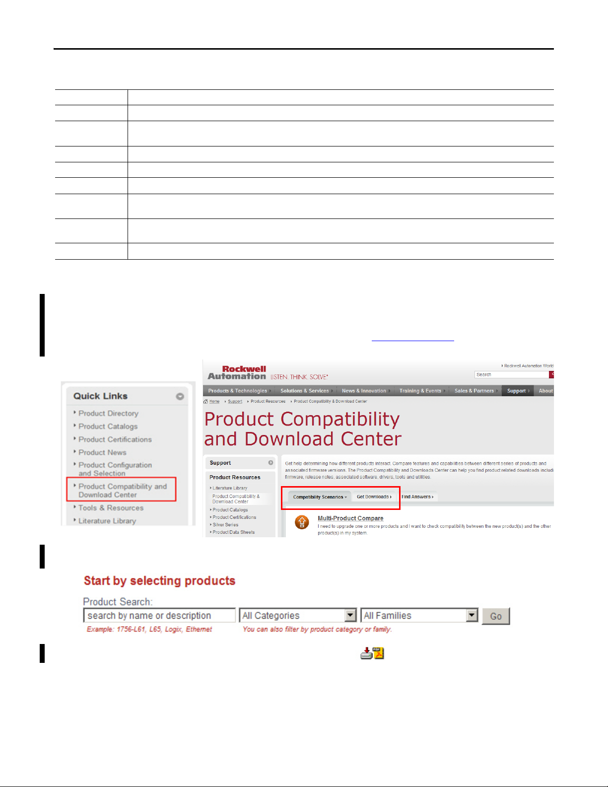
Product release notes are available online within the Product Compatibility and
Download Center.
1. From the Quick Links list on http://www.ab.com
, choose Product
Compatibility and Download Center.
2. From the Compatibility Scenarios tab or the Get Downloads tab, search
for and choose your product.
3. Click the download icon to access product release notes.
12 Rockwell Automation Publication 1734-UM013J-EN-P - July 2014

Preface
Additional Resources
These documents contain additional information concerning related products
from Rockwell Automation.
Resource Description
POINT I/O Selection Guide, publication 1734-SG001 Provides selection information for POINT I/O™ modules. Additional publication references
GuardLogix 5570 Controllers User Manual, publication 1756-UM022 Provides information on how to install, configure, program, and use GuardLogix 5570
GuardLogix 5570 Controller Systems Safety Reference Manual, publication 1756-RM099
GuardLogix Controller Systems Safety Reference Manual, publication 1756-RM093 Provides information on safety system requirements and describes the GuardLogix®
GuardLogix Controllers User Manual, publication 1756-UM020 Provides information on how to install, configure, program, and use GuardLogix
GuardLogix Safety Application Instructions Safety Reference Manual,
publication 1756-RM095
SmartGuard 600 Controllers Safety Reference Manual, publication 1752-RM001 Describes SmartGuard 600-specific safety requirements and controller features.
SmartGuard 600 Controllers User Manual, publication1752-UM001 Describes how to configure, operate, and troubleshoot the controller.
Field Potential Distributor Installation Instructions, publication 1734-IN059
POINT I/O 24V DC Expansion Power Supply Installation Instructions,
publication 1734-IN058
POINT I/O 120/240V AC Expansion Power Supply Installation Instructions,
publication 1734-IN017
POINT I/O Wiring Base Assembly Installation Instructions, publication 1734-IN511
POINT I/O One-piece Wiring Base Assembly Installation Instructions,
publication 1734-IN028
DeviceNet Modules in Logix5000 Control Systems User Manual, publication DNET-UM004 Provides information on how to connect the controller to the network.
ODVA Media Planning and Installation Guide, http://www.odva.org
Industrial Automation Wiring and Grounding Guidelines, publication 1770-4.1 Provides general guidelines for installing a Rockwell Automation industrial system.
Product Certifications website, http://www.ab.com Provides declarations of conformity, certificates, and other certification details.
Describes the required media components and how to plan for and install these required
are listed as well.
controllers in Studio 5000 Logix Designer projects.
Provides information on safety application requirements for GuardLogix 5570 controllers
in Studio 5000™ Logix Designer projects.
controller system.
controllers in RSLogix 5000 projects.
Provides reference information describing the GuardLogix Safety Application Instruction
Set.
Provides installation information on 1734-FPD distributors.
Provides installation information on 1734-EP24DC power supplies.
Provides installation information on 1734-EPAC power supplies.
Provides installation information on 1734-TB and 1734-TBS assemblies.
Provides installation information on 1734-TOP, 1734-TOPS, 1734-TOP3, and 1734-TOP3S
assemblies.
components.
You can view or download publications at
http://www.rockwellautomation.com/literature/
. To order paper copies of
technical documentation, contact your local Allen-Bradley® distributor or
Rockwell Automation sales representative.
Rockwell Automation Publication 1734-UM013J-EN-P - July 2014 13

Preface
Notes:
14 Rockwell Automation Publication 1734-UM013J-EN-P - July 2014

Chapter 1
POINT Guard I/O Overview
Top ic Pag e
Understand Suitability for Use 15
Safety Precautions 17
POINT Guard I/O Modules in CIP Safety Systems 17
Safety Application Requirements 21
Use the POINT Guard I/O safety modules in the POINT I/O platform to
distribute safety I/O on a safety-control network that meets the requirements up
to and including SIL CL3, and PLe, Cat. 4 as defined in IEC 61508, IEC 61511,
IEC 62061, and ISO 13849-1. POINT Guard I/O modules may be used with
1756 GuardLogix, 1768 Compact GuardLogix, or SmartGuard 600 controllers.
Understand Suitability for Use
You can configure the modules for use on DeviceNet networks by using the
network configuration tool, RSNetWorx™ for DeviceNet software. For EtherNet
networks, use the GuardLogix programming tool, the Logix Designer
application.
Rockwell Automation is not responsible for conformity with any standards,
codes, or regulations that apply to the combination of the products in your
application or use of the product. See Legislations and Standards
more information.
Take all necessary steps to determine the suitability of the products for the
systems, machine, and equipment with which it is used.
Know and observe all prohibitions of use applicable to these products.
Use this equipment within its specified ratings.
Never use these products for an application involving serious risk to life or
property without making sure that the system as a whole was designed to address
the risks and that the Rockwell Automation products are properly rated and
installed for the intended use within the overall equipment or system.
on page 179 for
Rockwell Automation Publication 1734-UM013J-EN-P - July 2014 15
Chapter 1 POINT Guard I/O Overview
TIP
Verify that the POINT Guard I/O firmware revision is correct prior to
commissioning the safety system. Firmware information for safety I/O modules
is available at
http://www.rockwellautomation.com/products/certification/safety
.
Field power must be applied to the 1734-IE4S module when updating
firmware.
Verify that a safety administrator conducts a risk assessment on the machine and
determines module suitability before installation.
ATTENTION: Personnel responsible for the application of safety-related
programmable electronic systems (PES) shall be aware of the safety
requirements in the application of the system and shall be trained in using the
system.
ATT EN TI ON : Use only appropriate components or devices complying with
relevant safety standards corresponding to the required safety category and
safety integrity level.
• Conformity to requirements of the safety category and safety integrity level
must be determined for the entire system.
• We recommend you consult a certification body regarding assessment of
conformity to the required safety integrity level or safety category.
You are responsible for confirming compliance with the applicable standards for
the entire system.
Table 1 - Requirements for Controlling Devices
Device Requirement Allen-Bradley Bulletin Safety Components
Emergency stop switches Use approved devices with direct opening mechanisms complying with IEC/EN 60947-
Door interlocking switches,
limit switches
Safety sensors Use approved devices complying with the relevant product standards, regulations, and
Relays with forcibly- guided
contacts, contac tors
Other devices Evaluate whether devices used are appropriate to satisfy the requirements of safety
5-1.
Use approved devices with direct opening mechanisms complying with IEC/EN 60947-
5-1 and capable of switching microloads of
24V DC, 3 mA.
rules in the country where used.
Use approved devices with forcibly-guided contacts complying with EN 50205. For
feedback purposes, use devices with contacts capable of switching micro loads of
24V DC, 3 mA.
category levels.
Bulletin 800F, 800T
Bulletin 440K, 440G, 440H for interlock switch
Bulletin 440P, 802T for limit switch
Any Guardmaster product
Bulletin 700S, 100S
-
16 Rockwell Automation Publication 1734-UM013J-EN-P - July 2014
POINT Guard I/O Overview Chapter 1
Safety Precautions
Observe these precautions for proper use of POINT Guard I/O modules.
ATTENTION: As serious injury may occur due to loss of required safety function,
follow these safety precautions.
• Never use test outputs as safety outputs. Test outputs are not safety outputs.
• Do not use Ethernet, DeviceNet, or ControlNet standard I/O data or explicit
message data as safety data.
• Do not use LED status indicators on the I/O modules for safety operations.
• Do not connect loads beyond the rated value to the safety outputs.
• Apply properly specified voltages to the module. Applying inappropriate
voltages may cause the module to fail to perform it’s specified function, which
could lead to loss of safety functions or damage to the module.
• Wire the POINT Guard I/O modules properly following the wiring requirements
and guidelines in Wire Modules
on page 58.
• Set unique network node addresses before connecting devices to the network.
• Perform testing to confirm that device wiring, configuration, and operation is
correct before starting system operation.
• Do not disassemble, repair, or modify the module. This may result in loss of
safety functions.
Installing and Replacing Modules
POINT Guard I/O Modules in CIP Safety Systems
ATTENTION:
• Clear previous configuration data before connecting devices to the network or
connecting input or output power to the device.
• Configure the replacement device properly and confirm that it operates
correctly.
• After installation of the module, a safety administrator must confirm the
installation and conduct trial operation and maintenance.
When cleaning modules, do not use the following:
• Thinner
• Benzene
• Acetone
POINT Guard I/O modules are used in the POINT I/O platform and
implement CIP Safety protocol extensions over EtherNet/IP and DeviceNet
networks to communicate safety messages. POINT Guard I/O modules connect
to EtherNet/IP or DeviceNet networks via these network adapters.
Table 2 - Network Adapters
Network System Adapter
EtherNet/IP GuardLogix 1734-AENT (firmware revision 3 or later)
DeviceNet SmartGuard or GuardLogix 1734-PDN
(1)
1734-AENTR
(1) Not compatible with 1734-ADN, 1734-ADNX, 1734-APB, or 1734-ACNR adapters.
Rockwell Automation Publication 1734-UM013J-EN-P - July 2014 17

Chapter 1 POINT Guard I/O Overview
Distributed I/O communication for safety I/O data is performed through safety
connections supporting CIP Safety over an EtherNet/IP or DeviceNet network.
Data processing is performed in the safety controller. The status and fault
diagnostics of POINT Guard I/O modules are monitored by a controller.
In addition to I/O state data, the modules include status data for monitoring I/O
faults within each circuit.
The configuration information of the modules can be protected by a password.
1734-IB8S Digital Input Module Features
• Safety digital inputs
– Safety devices, such as emergency stop push buttons, gate switches, and
safety light curtains, can be connected.
– Dual-channel mode evaluates consistency between two input signals
(channels), which allows use of the module for safety Category 3 and 4
and in applications rated up to and including Performance Level e/
SIL CL3.
– Single-channel mode evaluates one input signal (channel), which allows
use of the module for safety Category 2 and in applications rated up to
and including Performance Level d/SIL CL 2.
– You can configure a discrepancy time to control how long two channels
are allowed to be discrepant before a fault is declared.
– An external wiring short-circuit check is possible when inputs are wired
in combination with test outputs. The module must be wired in
combination with test outputs when this function is used.
– Independently adjustable on and off delays are available per channel.
• Test outputs (digital input modules only)
– Separate test outputs are provided for short-circuit detection of a safety
input (or inputs).
– Power (24V) can be supplied to devices, such as safety sensors.
– Test outputs can be configured as standard outputs.
– Specific test outputs can be used for broken-wire detection of a muting
lamp.
1734-OB8S Safety Digital Output Module Features
• Solid-state outputs
• Dual-channel mode provides redundant control by using two output
signals (channels), which allows use of the module for safety Category 3
and 4, and applications rated up to and including Performance Level e/
SIL CL3.
• Safety outputs can be pulse-tested to detect field wiring short circuits to
24V DC.
18 Rockwell Automation Publication 1734-UM013J-EN-P - July 2014

POINT Guard I/O Overview Chapter 1
1734-IE4S Safety Analog Input Module Features
• Connection of up to four voltage or current sensors.
• Sensor power outputs are individually current-limited and monitored.
• Measurement of process variables, such as temperature, pressure, or flow
rate.
• Seven configurable input ranges
(±10V, ±5V, 0…5V, 0…10V, 4…20 mA, 0…20 mA, Tachometer).
• Tachometer mode converts 24V DC switching signals into pulses per
second.
• Single-channel or dual-channel for SIL 3-rated safety devices and
applications.
• Dual-channel mode evaluates the consistency between two input signals
(channels), which allows use of the module in applications rated up to and
including SIL CL3/PLe/Cat. 4.
• You can configure a discrepancy time to control how long two channels are
allowed to be discrepant before a fault is declared.
Programming Requirements
Use the minimum software versions listed here.
Cat. No. Studio 5000 Environment
1734-IB8S,
1734-OB8S
1734-IE4S 21 18
(1) This version or later.
(2) If you are using digital POINT Guard I/O modules with the analog POINT Guard I/O module, you need to update the add-on
profiles to version 2.02.004 or later for the modules to be compatible with version 18 or later of RSLogix 5000 software and the
Studio 5000 environment. To find add-on profiles, go to http://www.rockwellautomation.com/support
(3) Dual-channel Analog ( DCA) safety application instruction is available in RSLogix 5000 software, version 20 or later and Studio
5000 environment, version 21 and later.
(1)
Versi on
21 17
RSLogix 5000 Software
(1)
Vers ion
(EtherNet/IP Network)
(2)
(3)
RSNetWorx for DeviceNet
Software Version
(DeviceNet Network)
9
10
.
(1)
Rockwell Automation Publication 1734-UM013J-EN-P - July 2014 19
Chapter 1 POINT Guard I/O Overview
Safety Communication
GuardLogix
Control ler
CompactBlock
Guard I/O™
POINT Guard I/O and POINT I/O
Standard Communication
Stratix Switch
GuardLogix
Control ler
Guard I/O
POINT Guard I/O and POINT I/O
Safety Communication
Standard Communication
SmartGuard
Control ler
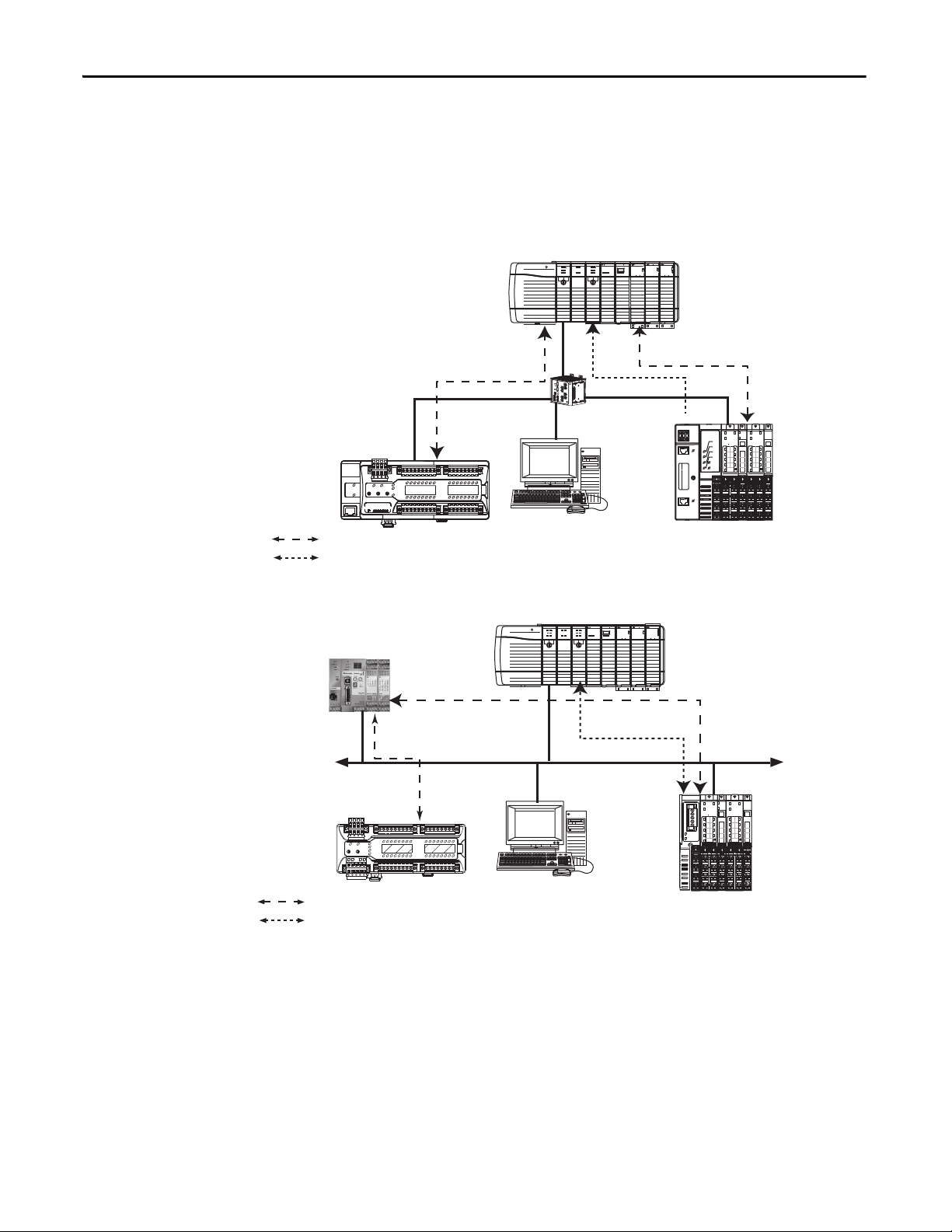
CIP Safety Architectures
Use POINT Guard I/O modules in EtherNet/IP or DeviceNet safety
architectures. Safety controllers control the safety outputs. Safety or standard
PLC controllers can control the standard outputs.
Figure 1 - POINT Guard I/O Modules in EtherNet/IP Safety Architecture
Figure 2 - POINT Guard I/O Modules in DeviceNet Safety Architectures
20 Rockwell Automation Publication 1734-UM013J-EN-P - July 2014

POINT Guard I/O Overview Chapter 1
Safety Application Requirements
POINT Guard I/O modules are certified for use in safety applications up to and
including Performance Level e (PLe/Cat. 4) and Safety Integrity Level 3
(SIL CL3) in which the de-energized state is the safe state. Safety application
requirements include evaluating probability of failure rates (PFD and PFH),
system reaction time settings, and functional verification tests that fulfill SIL 3
criteria.
Creating, recording, and verifying the safety signature is also a required part of
the safety application development process. Safety signatures are created by the
safety controller. The safety signature consists of an identification number, date,
and time that uniquely identifies the safety portion of a project. This includes all
safety logic, data, and safety I/O configuration.
For safety system requirements, including information on the safety network
number (SNN), verifying the safety signature, functional verification test
intervals, system reaction time, and PFD/PFH calculations, refer to the following
publications.
For safety requirements in Refer to
GuardLogix controller systems GuardLogix 5570 Controller Systems Safety Reference
Manual, publication 1756-RM099
SmartGuard 600 controller systems SmartGuard 600 Controllers Safety Reference Manual,
publication 1752-RM001
You must read, understand, and fulfill the requirements detailed in these
publications prior to operating a safety system that uses POINT Guard I/O
modules.
Rockwell Automation Publication 1734-UM013J-EN-P - July 2014 21

Chapter 1 POINT Guard I/O Overview
Notes:
22 Rockwell Automation Publication 1734-UM013J-EN-P - July 2014
Chapter 2
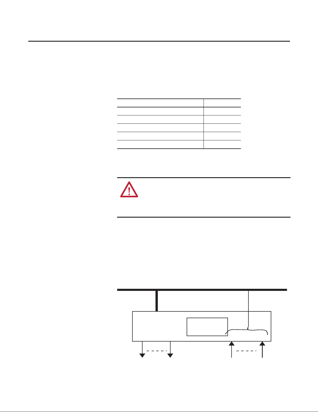
Output OFF
Input
Inputs to Network OFFNetworks
Safety
Status
44076
Safety Inputs, Safety Outputs, and Safety Data
Top ic Pag e
Safe States 23
Safety Inputs (1734-IB8S) 24
Safety Analog Inputs (1734-IE4S) 31
Safety Outputs (1734-OB8S) 39
I/O Status Data 42
Safe States
POINT Guard Digital I/O Modules
ATTENTION:
• The safe state of the outputs is defined as the off state.
• The safe state of the module and its data is defined as the off state.
• Use the POINT Guard I/O module only in applications where the off state is the
safe state.
These are the safe states of the digital POINT Guard I/O modules:
• Safety outputs: OFF
• Safety input data to network: OFF (single channel and
dual-channel equivalent)
• Safety input data to network: OFF/ON for input channels n/n+1
(dual-channel complimentary)
Figure 3 - Safety Status
The module is designed for use in applications where the safe state is the off state.
Rockwell Automation Publication 1734-UM013J-EN-P - July 2014 23
Chapter 2 Safety Inputs, Safety Outputs, and Safety Data
TIP
Where:
T0 = Test Output 0 T1M = Test Output 1 with Muting
T2 = Test Output 2 T3M = Test Output 3 with Muting
I0…I7 = Safety Inputs
Safety Input
Ter m in a l
External
Contac t
POINT Guard I/O Analog Input Module
These are the safe states of the POINT Guard I/O analog input module:
• Safety input data to network in single-channel configuration: 0 (OFF)
• Safety input data to network in dual-channel equivalent configuration:
– If a diagnostic fault occurs, the signal for the faulted channel is set to 0
(OFF).
– If a dual-channel discrepancy fault occurs, the dual-channel inputs
continue to report actual input signals.
Safety Inputs (1734-IB8S)
Safety inputs are used to monitor safety input devices.
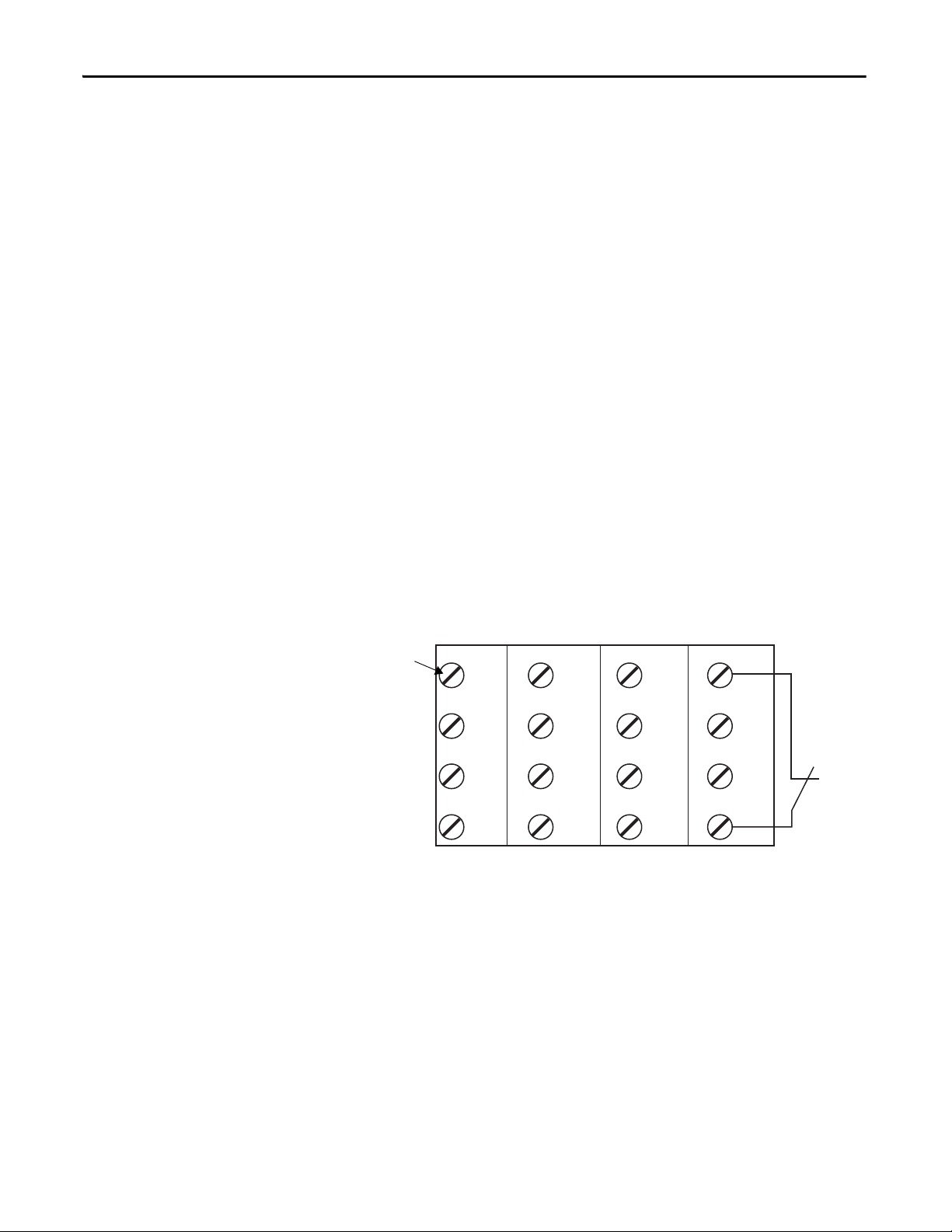
Using a Test Output with a Safety Input
A test output can be used in combination with a safety input for short circuit,
cross-channel, and open-circuit fault detection. Configure the test output as a
pulse test source and associate it to a specific safety input.
The test output can also be configured as a power supply to source 24V DC
to an external device, for example, a light curtain.
Figure 4 - Example Use of a POINT Guard I/O Input Module
I0 I1 I4 I5
0
I2 I3 I6 I7
2
COM COM COM COM
4
TO T1M T2 T3M
6
1
3
5
7
0
2
4
6
1
3
5
7
24 Rockwell Automation Publication 1734-UM013J-EN-P - July 2014
Safety Inputs, Safety Outputs, and Safety Data Chapter 2
X
OUT
Y
On
Off
External Contact
Short-circuit between Input Signal Lines and Power
Supply (positive side)
External Contact
Short-circuit between Input Signal Lines
44079
Figure 5 - Test Pulse in a Cycle
For the 1734-IB8S module, the pulse width (X) is typically 525 μs; the pulse
period (Y) is typically 144 ms.
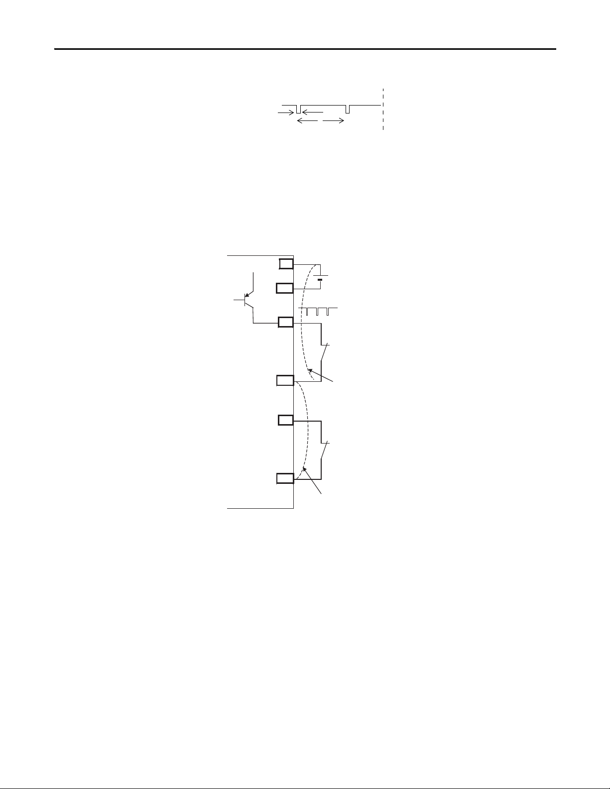
When the external input contact is closed, a test pulse is output from the test
output terminal to diagnose the field wiring and input circuitry. By using this
function, short-circuits between inputs and 24V power, and between input signal
lines and open circuits can be detected.
Figure 6 - Short-circuit between Input Signal Lines
24V
IN+
COM
T0
24V
0V
IN0
T1
IN1
Rockwell Automation Publication 1734-UM013J-EN-P - July 2014 25
Chapter 2 Safety Inputs, Safety Outputs, and Safety Data
24V
0V
Tes t O utp ut 0
Input Terminal 0
External Device
Faul t De tect ed
ON
OFF
ON
OFF
ON
OFF
ON
OFF
24V
0V
ON
OFF
Safety Input 0
Status
Fault Detection
ON
OFF
ON
OFF
ON
OFF
Safety Input 0
Status
Safety Input 0
Data
Safety Input 0
Data
Input Terminal 0
Normal Operation
External Device
Tes t O utp ut 0
Safety
I/O
Network
Data Sent
to the
Control ler
Safety
I/O
Network
Data Sent
to the
Control ler
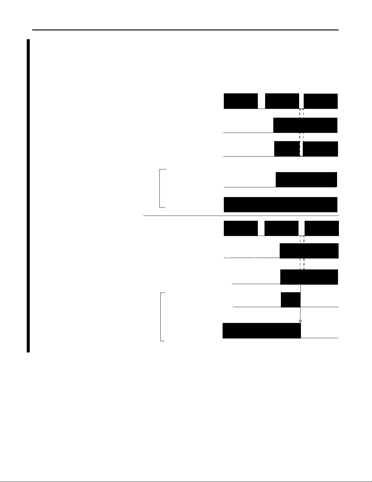
Single-channel Mode
If an error is detected, safety input data and safety input status turn off.
Figure 7 - Normal Operation and Fault Detection (not to scale)
26 Rockwell Automation Publication 1734-UM013J-EN-P - July 2014

Safety Inputs, Safety Outputs, and Safety Data Chapter 2
IMPORTANT
IMPORTANT
Dual-channel Mode and Discrepancy Time
To support dual-channel safety devices, the consistency between signals on two
channels can be evaluated. Either equivalent or complementary can be selected.
If the length of a discrepancy between the channels exceeds the configured
discrepancy time (0…65,530 ms in increments of 10 ms), the safety input data
and the individual-safety input status turn off for both channels. In Dual-channel
Complimentary mode, the safety input data goes to off/on for input channels
n/n+1 respectively as described in Ta b l e 3
The dual-channel function is used with two consecutive inputs that are paired
together, starting at an even input number, such as inputs 0 and 1, 2 and 3,
and so on.
If you are using the safety application instructions with a GuardLogix
controller, set the module’s inputs to Single (default). Do not use the modules’
dual-channel mode as this functionality is provided by the safety application
instructions.
.
This table shows the relation between input terminal states and controller input
data and status.
Table 3 - Terminal Input Status and Controller I/O Data
Dual-channel Mode Input Terminal Controller Input Data and Status Dual-channel
IN0 IN1 Safety
Input 0 Data
Dual-channels, Equivalent OFF OFF OFF OFF ON ON OFF Normal
OFF ON OFF OFF OFF OFF OFF Fault
ON OFF OFF OFF OFF OFF OFF Fault
ON ON ON ON ON ON ON Normal
Dual-channels, Complementary OFF OFF OFF ON OFF OFF OFF Fault
OFF ON OFF ON ON ON OFF Normal
ON OFF ON OFF ON ON ON Normal
ON ON OFF ON OFF OFF OFF Fault
Safety
Input 1 Data
Safety
Input 0 Status
Safety
Input 1 Status
Resultant
Data
Dual-channel
Resultant
Rockwell Automation Publication 1734-UM013J-EN-P - July 2014 27
Chapter 2 Safety Inputs, Safety Outputs, and Safety Data
ON
OFF
IN0
Safety Input 0
Data
IN1
Faul t Dete cted
Discrepancy Time
Safety
I/O
Network
Data Sent
to the
Control ler
ON
OFF
ON
OFF
ON
OFF
ON
OFF
ON
OFF
ON
OFF
IN0
Safety Input 0, 1
Status
IN1
Fault Detection
ON
OFF
ON
OFF
ON
OFF
Discrepancy Time
Safety Input 0, 1
Status
Safety Input 1
Data
Safety Input 1
Data
Safety Input 0
Data
Normal Operation
Safety
I/O
Network
Data Sent
to the
Contro ller
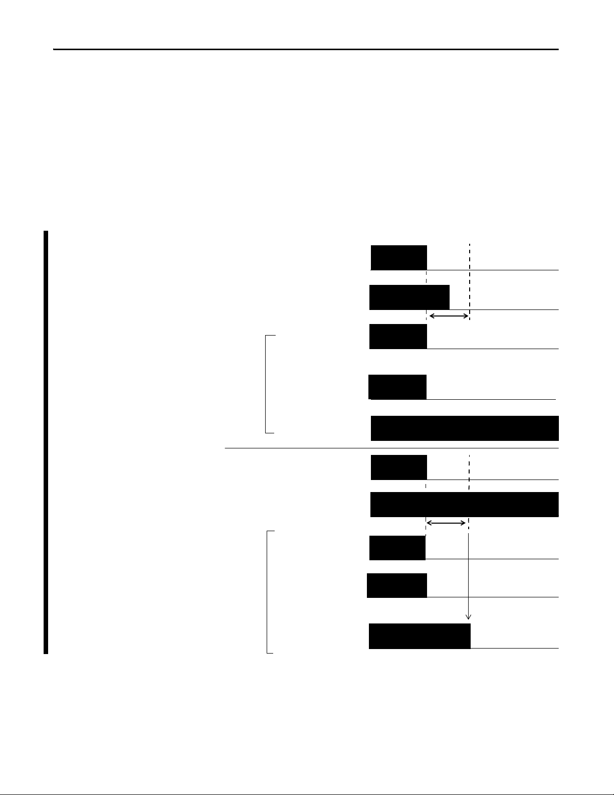
Dual-channel, Equivalent
In Equivalent mode, both inputs of a pair should be in the same (equivalent)
state. When a transition occurs in one channel of the pair prior to the transition
of the second channel of the pair, a discrepancy occurs. If the second channel
transitions to the appropriate state prior to the discrepancy time elapsing, the
inputs are considered equivalent. If the second transition does not occur before
the discrepancy time elapses, the channels will fault. In the fault state, the input
and status for both channels are set low (OFF). When configured as an
equivalent dual pair, the data bits for both channels will always be sent to the
controller as equivalent, both high or both low.
Figure 8 - Equivalent, Normal Operation and Fault Detection (not to scale)
28 Rockwell Automation Publication 1734-UM013J-EN-P - July 2014
Safety Inputs, Safety Outputs, and Safety Data Chapter 2
ON
OFF
IN0
Safety Input 0
Data
IN1
Faul t Dete cted
Discrepancy Time
ON
OFF
ON
OFF
ON
OFF
ON
OFF
ON
OFF
ON
OFF
IN0
Safety Input 0, 1
Status
IN1
Fault Detect ion
ON
OFF
ON
OFF
ON
OFF
Discrepancy Time
Safety Input 0, 1
Status
Safety Input 1
Data
Safety Input 1
Data
Safety Input 0
Data
Normal
Operation
Safety
I/O
Network
Data Sent
to the
Control ler
Safety
I/O
Network
Data Sent
to the
Control ler
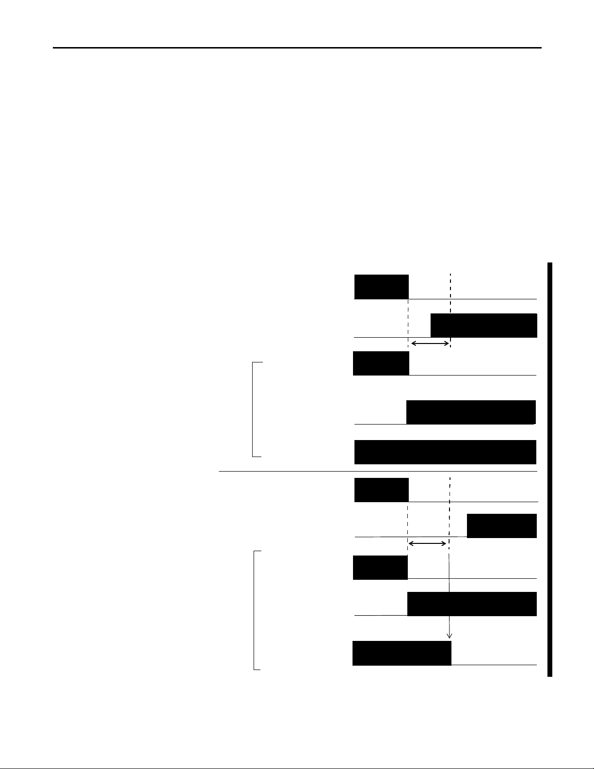
Dual-channels, Complementary
In Complementary mode, the inputs of a pair should be in the opposite
(complementary) state. When a transition occurs in one channel of the pair prior
to the transition of the second channel of the pair, a discrepancy occurs. If the
second channel transitions to the appropriate state prior to the discrepancy time
elapsing, the inputs are considered complementary.
If the second transition does not occur before the discrepancy time elapses, the
channels will fault. The fault state of complementary inputs is the
even-numbered input turned off and the odd-numbered input turned ON.
Note that if faulted, both channel status bits are set low. When configured as a
complementary dual-channel pair, the data bits for both channels will always be
sent to the controller in complementary, or opposite states.
Figure 9 - Complementary, Normal Operation and Fault Detection (not to scale)
Rockwell Automation Publication 1734-UM013J-EN-P - July 2014 29

Chapter 2 Safety Inputs, Safety Outputs, and Safety Data
44094
On-delay
ON
OFF
ON
OFF
Input Signal
Safety Input
Network Data
44095
Safety Input
Network Data
Off-delay
Input Signal
ON
OFF
ON
OFF
Safety Input Fault Recovery
If an error is detected, the safety input data remains in the OFF state. Follow this
procedure to activate the safety input data again.
1. Remove the cause of the error.
2. Place the safety input (or safety inputs) into the safe state.
3. Allow the input-error latch time to elapse.
After these steps are completed, the I/O indicator (red) turns off.
The input data is now active.
Input Delays
On-delay—An input signal is treated as Logic 0 during the on-delay time
(0…126 ms, in increments of 6 ms) after the input contact’s rising edge. The
input turns on only if the input contact remains on after the on-delay time has
elapsed. This helps prevent rapid changes of the input data due to
contact bounce.
Figure 10 - On-delay
Off-delay—An input signal is treated as Logic 1 during the off-delay time
(0…126 ms, in increments of 6 ms) after the input contact’s falling edge.
The input turns off only if the input contact remains off after the off delay time
has elapsed. This helps prevent rapid changes of the input data due to contact
bounce.
Figure 11 - Off-delay
30 Rockwell Automation Publication 1734-UM013J-EN-P - July 2014

Safety Inputs, Safety Outputs, and Safety Data Chapter 2
IMPORTANT
IMPORTANT
EXAMPLE
Safety Analog Inputs (1734-IE4S)
Safety analog-input channels can be configured for current, voltage, or
tachometer inputs, and for input type: single-channel or dual-channel equivalent.
If you are using the module with a GuardLogix controller, set the module’s
inputs to Single (default). Do not use the modules’ dual-channel equivalent
mode with the GuardLogix dual channel safety application instructions, as
dual-channel functionality is provided by the GuardLogix instructions.
Input Range
You configure the module for the following voltage or current input ranges, or for
tachometer inputs.
• ±10V
• ±5V
• 0…5V
• 0…10V
• 4…20 mA
• 0…20 mA
• Tachometer (1…1000 Hz)
When ±10V and ±5V ranges are selected, you must make sure that a
broken-wire condition is not a safety hazard. A broken wire causes the analog
value to transition to 0, which is within the valid input range. Therefore, status
bits will not indicate the broken-wire condition.
Scaling
The module converts input signals to the engineering units specified when you
configure the module. You set the High Engineering value and the Low
Engineering value to which the module scales the input signal before sending the
data to the controller’s application program.
The module is configured as follows:
• Input Range = 0…10V
• Low Engineering value = 0
• High Engineering value = 10,000
If the incoming signal is 1V, the data is 1000.
If the incoming signal is 5.5V, the data is 5500.
Rockwell Automation Publication 1734-UM013J-EN-P - July 2014 31
Chapter 2 Safety Inputs, Safety Outputs, and Safety Data
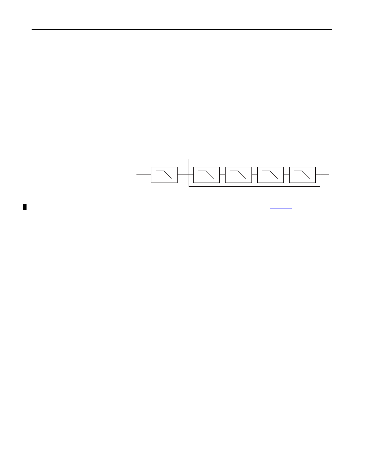
Configurable Digital Filter Settings
N = 1 Hz, 5 Hz, 10 Hz, or 50 Hz
Anti-alias Filter
10 Hz
1 pole 1 pole 1 pole 1 pole 1 pole
NNNN
Digital Input Filter
A single-pole, anti-aliasing filter of 10Hz is followed by a four-pole digital filter.
Choose from the following available corner frequencies.
• 1 Hz
• 5 Hz
• 10 Hz
• 50 Hz
The default input filter setting is 1Hz.
Figure 12 - Filter Operation
The filter setting affects the module’s step response. See the technical
specifications for the 1734-IE4S module, beginning on page 164
.
For the analog input modes, the input filter settings set the low-pass filter to filter
out noise that may be present on the signal. In Tachometer mode, the input filter
removes noise that may be present on the calculated frequency, effectively
changing how rapidly the tachometer frequency changes to provide a value with
less jitter.
Sensor Power Supply
You can configure the module to supply power to the connected sensors, or you
can supply power to the sensors from an external power supply. To comply with
UL restrictions, field power and connected devices must be powered by a single,
Class 2-complaint power supply.
We recommend that you configure the module to supply power to the sensors
because this lets the module detect if a sensor loses power, if the sensor is drawing
too much power, or if there is a short in the power wiring to the sensor.
At powerup or after a reconfiguration, each sensor power supply is tested by
being turned on for 500 ms.
32 Rockwell Automation Publication 1734-UM013J-EN-P - July 2014

Safety Inputs, Safety Outputs, and Safety Data Chapter 2
TIP
IMPORTANT
TIP
When a channel is configured for module sensor power, a sensor power
diagnostic is executed on that channel at powerup to make sure that the sensors
are not drawing over- or under-current and that channel-to-channel shorts are
not present.
When a sensor power over-current condition occurs, it may take as much as 15
seconds longer than the configured latch time for channel status to recover
after the over-current condition is cleared.
If you use an external power supply, you must monitor the system for the
following:
• The supply voltage must be within the sensors’ operating range.
• The sensors’ current draw must not be over- or under-current, which could
indicate a problem with the components of the sensor.
• Channel-to-channel shorts must be detected, if they occur.
Channel Offset
You can configure an offset when differences in the sensors nominal input signals
would otherwise exceed the desired discrepancy deadband. Use the Channel
Offset if you are using two sensors of different types to measure the same variable;
that is, sensors from two different vendors that may not give exactly the same data
value for a given temperature or pressure. Use the Channel Offset to bring the
data values back together. You can also use the Channel Offset with two identical
sensors that are physically offset from each other.
The channel offset is applied before the channel discrepancy is evaluated.
The Channel Offset is applied only during the evaluation of discrepancy between
two channels configured for Dual Channel and is not applied to any of the Process
Alarms. Therefore, if you are using two sensors to measure the same process
variable, and these sensors read different values, you may need to set the Process
Alarms to different values based on the sensor readings.
Process Alarms
Process alarms alert you when an analog input value has exceeded the configured
high or low limits for each channel. Process alarms are set at four configurable
trigger points.
• High High alarm
• High alarm
• Low alarm
• Low Low alarm
Rockwell Automation Publication 1734-UM013J-EN-P - July 2014 33
Chapter 2 Safety Inputs, Safety Outputs, and Safety Data
IMPORTANT
High High alarm turns OFF. High alarm remains ON.
High High alarm turns ON. High alarm remains ON.
High alarm turns
ON.
High alarm turns OFF.
Normal input
range
Low alarm turns
ON.
Low alarm turn s
OFF.
Low Low alarm turns OFF. Low alarm remains ON.
Low Low alarm turns ON. Low alarm remains ON.
Alarm deadbands
High High Alarm
High Alarm
Low Low Alarm
Low Alar m
You can configure a tolerance range, called a deadband, to work with process
alarms. This deadband lets the process alarm status bit remain set, despite the
alarm condition disappearing, as long as the data remains within the deadband of
the process alarm.
If you are using the safety application instructions with a GuardLogix
controller, do not use the module’s process alarms. Instead, perform analog
range checking in your application logic.
Figure 13 - Alarms
Using a Single-channel Sensor
You must address the following requirements to meet SIL 3 with a single-channel
sensor.
• The module’s ±10V and ±5V analog input modes must not be used for
SIL 3 with a single-channel sensor because 0V falls within the valid input
range. Therefore, a stuck at ground fault cannot be detected.
• In a single-channel sensor system, you must use other methods to make
34 Rockwell Automation Publication 1734-UM013J-EN-P - July 2014
• If you are using a 3-wire sensor, you must verify its behavior to make sure
sure a channel-to-channel short cannot occur because these faults cannot
be detected.
that if it loses its ground connection, the signal is 0 (safe state) at the
module input when the fault occurs.

Safety Inputs, Safety Outputs, and Safety Data Chapter 2
IMPORTANT
High High Alarm
High Alarm
Low Low A larm
Low Alar m
Channel A
Channel B
Discrepancy Time = 250 ms
Faul t Pre sent
Input Status
Deadband
Difference between Channel A and Channel B
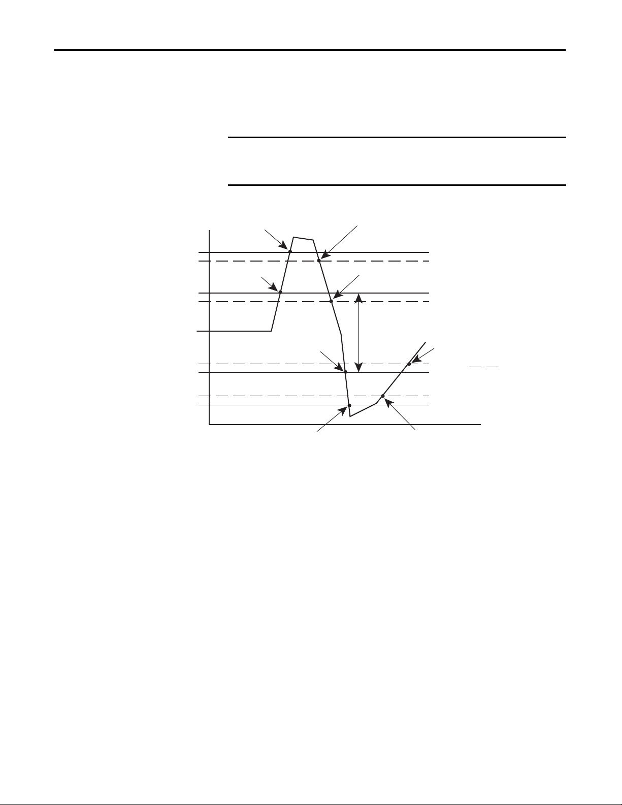
Dual-channel Equivalent Mode
If you are using the module with a GuardLogix controller, set the module’s
inputs to Single (default). Do not use the modules’ dual-channel mode as this
functionality is provided by the GuardLogix safety application instructions.
The 1734-IE4S module supports Dual-channel Equivalent mode. In
Dual-channel Equivalent mode, the values of both inputs of a pair must be within
a configured tolerance range (discrepancy deadband). If the difference between
the channel values exceeds the deadband for longer than the configured
discrepancy time, a discrepancy fault is declared. When a dual-channel
discrepancy fault occurs, the input status values for both channels are set low
(off ) and the actual input values are reported. The fault is cleared when the
difference between the channel’s values falls back within the discrepancy
deadband tolerance range for the discrepancy time.
Figure 14
illustrates module operation in dual-channel equivalent mode. At A,
the difference between the channel values exceeds the discrepancy deadband
tolerance range and the discrepancy timer starts. When the timer expires at B, a
dual-channel discrepancy fault occurs and the inputs status bits are set low. At C,
the values fall back within the discrepancy deadband and the discrepancy timer
starts again. When the timer expires at D, and the values are still within the
discrepancy deadband, the fault is cleared. At E, the difference between the
channels exceeds the discrepancy deadband and the discrepancy timer starts. A
discrepancy fault occurs again at F, when the timer expires and the difference
between the channel values remains greater than the discrepancy deadband.
Figure 14 - Timing Diagram
250 ms
1
0
1
250 ms
250 ms
0
A B C
Rockwell Automation Publication 1734-UM013J-EN-P - July 2014 35
D
E F

Chapter 2 Safety Inputs, Safety Outputs, and Safety Data
IMPORTANT
Low pulses are offset.
Sensor 1
Sensor 2
Low pulses occur at the same time, causing a fault.
Sensor 1
Sensor 2
Tachometer Mode
In Tachometer mode, the module measures digital pulses between 0 and 24V
DC and converts them into a frequency or pulses per second. Therefore, you can
use 24V DC proximity sensors or 5V DC encoders, for example. The
Tachometer function does not sense direction, so using a differential encoder will
not yield direction data. Tachometer mode could be used, for example, to
measure rotational speed of an axis connected to a gear.
Tachometer mode can operate as SIL 2 single-channel. SIL 3 is achievable by
using two sensors, the dual-low detection parameter, and user program logic.
Safety reaction time is dependent on the signal frequency.
When using two sensors in a dual-channel configuration, position the sensors
to make sure the low pulses occur at different times. If you have configured the
module for dual low detection and both sensors are low at the same time, a
fault will be declared.
Figure 15 - Sensor Pulses in Dual-channel Configuration
Signal Measurement
The edge-to-edge time of the pulse determines the frequency of the signal in
pulses per second. The frequency range is 1 Hz…1 kHz.
In Tachometer mode, you define how the signal is measured, either on the falling
(non-inverted) or rising (inverted) edge. For NPN-style sensors (sensor sinks),
use falling edge. For PNP-style sensors (sensor sources), use rising edge.
36 Rockwell Automation Publication 1734-UM013J-EN-P - July 2014
Depending on your application, you may need to install an appropriately-sized
pull-up resistor for falling-edge signal measurements or a pull-down resistor for
rising-edge signal measurements.

Figure 16 - Pulse Trains
Ideal Pulse Train
Falling and rising edges
are well-defined.
Rising edges are not
well-defined.
Falling e dges are no t
well-defined.
Falling Edge Rising Edge
Pull-down resistor helps define falling edges.
Pull-up resistor helps define rising edges.
Falling edge measurement
Rising edge measurement
Off and On Signal Levels
Safety Inputs, Safety Outputs, and Safety Data Chapter 2
You configure the Off and On levels, in 1V increments, for the signal. When
selecting these levels, you should assume a tolerance of at least ±0.5V. For
example, if you set the On Level to 10V, you can expect the module to recognize a
signal between 9.5 and 10.5V as On. While the module’s accuracy when
measuring the analog signal is very good, Tachometer mode emphasizes a wider
voltage range and speed to be able to measure pulse widths accurately.
Also consider the variance of the voltage output from your sensor when making
the On and Off Level settings. If possible, we recommend selecting On Levels
that are 2V below and Off Levels that are 2V above the actual thresholds of your
device’s expected output voltage level.
Determining Frequency in Pulses per Second
The edge-to-edge time of either the falling or rising edge of the pulse determines
the frequency in pulses per second.
A single pulse, by itself, does not generate a non-zero frequency. To report a
frequency of 1 Hz, two falling or rising edge pulses must be detected within 1
second. The module reports 0 Hz until 1 Hz is detected. For example, if a falling
or rising edge is not detected for 1.02 seconds after the previous edge, the module
reports 0 Hz.
Rockwell Automation Publication 1734-UM013J-EN-P - July 2014 37

Chapter 2 Safety Inputs, Safety Outputs, and Safety Data
A B C
1 kHz
1 Hz
Frequenc y = 0
Actual values are
repor ted.
Monitor frequency via an
alternate method.
Overfrequency
condition can be
cleared.
Frequency = 1 Hz
Overfrequency bit is set to 0.
Frequency = 1000 Hz
Overfrequency Bit Operation
When the frequency exceeds 1 kHz, the module reports a data value of 1 kHz,
sets the Overfrequency status bit to 0, and latches it. While the Overfrequency
bit is set to 0, you must use an alternate method to monitor the frequency of the
system because the value reported by the module is latched at 1 kHz. Once you
have verified that the frequency is lower than 1 kHz, you may reset the
Overfrequency condition by setting the Reset Tach bit, which lets the module
begin measuring the frequency of field pulses again.
If you set the Reset Tach bit while the frequency is still above 1 kHz, the
Tachometer Overfrequency bit transitions to 1 (within range) momentarily.
However, as soon as the module begins measuring pulses, it will detect another
overfrequency condition and immediately set the Tachometer Overfrequency bit
to 0 again. The Reset Tach bit is edge-sensitive.
ATT EN TI ON : Before resetting the Overfrequency condition, you must use
another method to verify that the actual frequency is lower than 1 kHz.
See Output Assemblies
Overfrequency bit.
Figure 17 - Overfrequency Operation
In Figure 17, the module reports a frequency of 0 Hz until the frequency of the
system reaches 1 Hz at A, when the module begins reporting the actual value. At
B, the frequency exceeds 1 kHz, the Overfrequency bit is set to 0, and the module
continues to report a data value of 1 kHz. Between B and C, you must monitor
the frequency by an alternate method because the value reported by the module
may not be accurate. After C, the Overfrequency condition can be cleared,
provided you have used an alternate method to verify that the actual frequency is
below 1 kHz.
on page 192 for more information on resetting the
38 Rockwell Automation Publication 1734-UM013J-EN-P - July 2014

Safety Inputs, Safety Outputs, and Safety Data Chapter 2
IMPORTANT
44096
X
Y
OUT
On
Off
ON
OFF
OUT0
Safety Output
0, 1
Status
OUT0
OUT1
OUT1
Safety Output
0, 1
Status
Fault Detection
Error
Detected
ON
OFF
ON
OFF
ON
OFF
ON
OFF
ON
OFF
Normal Oper ation
Safety
I/O
Network
Data Sent
to the
Controller
Safety
I/O
Network
Data Sent
to the
Controller
Safety Outputs (1734-OB8S)
Read this section for information about safety outputs.
Safety Output with Test Pulse
When the safety output is on, the safety output can be configured to pulse test
the safety output channel. By using this function, you can continuously test the
safety output’s ability to remove power from the module’s output terminals. If an
error is detected, the safety output data and individual safety output status turn
off.
Figure 18 - Test Pulse in a Cycle
For the 1734-OB8S module, the pulse width (X) is typically 475 μs; the pulse
period (Y) is typically 575 ms.
To prevent the test pulse from causing the connected device to malfunction,
pay careful attention to the input response time of the output device.
Dual-channel Mode
When the data of both channels is in the on state, and neither channel has a fault,
the outputs are turned on. The status is normal. If a fault is detected on one
channel, the safety output data and individual safety output status turn off for
both channels.
Figure 19 - Dual-channel Setting (not to scale)
Rockwell Automation Publication 1734-UM013J-EN-P - July 2014 39

Chapter 2 Safety Inputs, Safety Outputs, and Safety Data
IMPORTANT
TIP
Safety Output Fault Recovery
If a fault is detected, the safety outputs are switched off and remain in the off
state. Follow this procedure to activate the safety output data again.
1. Remove the cause of the error.
2. Command the safety output (or safety outputs) into the safe state.
3. Allow the output-error latch time to elapse.
After these steps are completed, the I/O indicator (red) turns off.
The output data can now be controlled.
Stuck high faults require a module power reset to clear the error.
Muting Lamp Operation (1734-IB8S)
Beginning with firmware revision 1.002, the operation of the muting status bits
for the test outputs T1 and T3 has changed. Test outputs T1 and T3 are
controlled by your PLC processor program to illuminate a muting lamp. Muting
lamp status is monitored with a test that runs periodically during every test
interval to detect a burned-out lamp. The test runs repeatedly when the test
output is commanded on. The figure below explains how muting lamp operation,
status, and fault detection are monitored.
The lamp test interval is 3 seconds. Two consecutive failed lamp tests are
required to declare a burned-out lamp condition. The lamp test may not run
immediately after the test output is energized. It starts at the next 3-second
interval. To allow time for two consecutive test intervals, program a minimum
Test Output On Time of 6 seconds.
40 Rockwell Automation Publication 1734-UM013J-EN-P - July 2014

Figure 20 - Muting Lamp Timing Diagram
IMPORTANT
Safety Inputs, Safety Outputs, and Safety Data Chapter 2
Ta b l e 4 shows the expected behavior of the muting status for test outputs T1 and
T3. Keep these points in mind as well:
• When power is applied to the 1734-IB8S module, and T1 or T3 remains
commanded off, the muting status defaults to on.
This bit operation is designed to help prevent erroneous muting
instruction faults from the GuardLogix controller. This bit status may not
be the true indication of a burned-out lamp.
Before checking the state of the corresponding muting status, be sure the test
output is commanded on. Once the test output is commanded on, a maximum
time of 6 seconds is required for the module to detect a burned-out lamp.
Rockwell Automation Publication 1734-UM013J-EN-P - July 2014 41

Chapter 2 Safety Inputs, Safety Outputs, and Safety Data
• If a muting lamp circuit is open when power is applied to the module, the
condition is detected when the test output is commanded on.
• When a lamp burns out and is replaced, the fault (muting status bit)
returns to the normal condition, independent of the state of the test
output.
Table 4 - Muting Status Bit Operation
I/O Status Data
Tes t Outp ut
Commanded
State
ON Bad (open circuit) 0 Repair lamp.
ON Good 1 Normal condition. Lamp is operating properly.
OFF Bad (open c ircuit) 0 If lamp remains OFF after T1/ T3 output cycled, repair lamp.
OFF Good 1 Normal co ndition.
Lamp Condition Muting
Status
Bit
Description
In addition to I/O data, the module provides status data for monitoring the I/O
circuits. The status includes diagnostic data that can be read by the controllers
with 1 = ON/Normal and 0 = OFF/Fault/Alarm.
Digital I/O Status Data
The following data is monitored:
• Individual Point Input Status
• Combined Input Status
• Individual Point Output Status
• Combined Output Status
• Individual Test Output Status
• Individual Output Monitor (actual ON/OFF state of the outputs)
Individual Point status indicates whether each safety input, safety output, or test
output is normal (normal: ON, faulted: OFF). For fatal errors, communication
connections may be broken, so the status data cannot be read. Status bits are OFF
in the controller data table when the connection is lost.
Combined status is provided by an AND of the status of all safety inputs or all
safety outputs. When all inputs or outputs are normal, the respective combined
status is ON. When one or more of them has an error, the respective combined
status is OFF. This is known as the combined safety input status or combined
safety output status.
42 Rockwell Automation Publication 1734-UM013J-EN-P - July 2014

Safety Inputs, Safety Outputs, and Safety Data Chapter 2
Analog I/O Status Data
Individual input status indicates whether each analog input point is normal
(ON) or faulted (OFF). In addition, the following diagnostic data is monitored:
• User 24V Supply Overrange or Underrange
• Sensor Power Overcurrent or Undercurrent
• Channel Signal Overrange or Underrange
• Broken Wire Detected (4…20 mA current mode)
• Single-channel Discrepancy Error (channel fault)
In SIL 2 or SIL 3 operation, a single-channel discrepancy error occurs
when both measurements (internal to the module) of the same input signal
are not within tolerance. If a single-channel discrepancy occurs, indicating
a problem with the module, input status is set to zero and a zero input
value is reported for that channel.
• SIL 3 Dual-channel Discrepancy Error (channel fault)
• Alarms
– High High and Low Low Alarm Overrange or Underrange
– High and Low Alarms Overrange or Underrange
– Dual-channel Tachometer Dual Low Inputs Detected
– Tachometer Frequency Overrange or Underrange
The alarm status is reported in the Alarm Status attribute for each channel.
Rockwell Automation Publication 1734-UM013J-EN-P - July 2014 43

Chapter 2 Safety Inputs, Safety Outputs, and Safety Data
Notes:
44 Rockwell Automation Publication 1734-UM013J-EN-P - July 2014
Chapter 3
TIP
Guidelines for Placing Power Supplies and
Modules in a System
Top ic Pag e
Choosing a Power Supply 45
Power Supply E xample s 46
Placing Series A Digital and Analog Modules 48
Choosing a Power Supply
The POINTBus™ backplane includes a 5V communication bus and field power
bus that get their power from a communication adapter or expansion power
supplies. All POINT I/O modules are powered from the POINTBus backplane
by either the adapter or expansion power supply. POINT I/O adapters have
built-in power supplies. Use the information and examples in this chapter to
determine if you need an expansion power supply in your system.
ATTENTION: To comply with the CE Low Voltage Directive (LVD), this equipment
and all connected I/O must be powered from a safety extra-low voltage (SELV)
or protected extra-low voltage (PELV) compliant source.
To comply with UL restrictions, field power and connected devices must be
powered from a single Class 2-compliant power supply.
The following Rockwell Automation 1606 power supplies are SELV- and
PELV-compliant, and they meet the isolation and output hold-off time
requirements of the SmartGuard 600 controller:
• 1606-XLP30E
• 1606-XLP50E
• 1606-XLP50EZ
Follow the safety precautions listed in Chapter 1
described in Chapter 4
before connecting a power supply to the system.
• 1606-XLP72E
• 1606-XLP95E
• 1606-XLDNET4
and the wiring guidelines
• 1606-XLSDNET4
To choose which types of power supplies meet your requirements, you must
consider the power consumption requirements for the 5V and 24V bus when
designing a POINTBus backplane.
Rockwell Automation Publication 1734-UM013J-EN-P - July 2014 45

Chapter 3 Guidelines for Placing Power Supplies and Modules in a System
IMPORTANT
IMPORTANT
Choose from these power supplies for the POINTBus backplane and field
power:
• Use the 1734-EP24DC expansion power supply to provide an additional
10 A of 24V DC field power and provide an additional 1.3 A of 5V current
to the I/O modules to the right of the power supply.
• Use the 1734-FPD field power distributor to provide an additional 10 A of
24V DC field power, and to pass through all POINT I/O backplane
signals including the 5V bus supplied to the left, without providing
additional POINTBus backplane power. This lets you isolate field power
segments.
• Use the 1734-EPAC expansion power supply (for standard I/O modules)
to provide an additional 10 A of 120/240V AC field power and provide an
additional 1.3 A of 5V current to the I/O modules to the right of the
power supply.
If you use the 1734-EPAC expansion power supply to the left of the POINT
Guard I/O modules, you must use a 1734-FPD field power distributor or
1734-EP24DC expansion power supply to isolate POINT Guard I/O field power
from the AC field supply.
Establishing and maintaining communication (connection) between the
module and the controller requires 5V POINTBus power.
Power Supply Examples
Refer to the POINT I/O Selection Guide, publication 17
information on compatible power supplies.
Use these valid power-supply example configurations to help you understand
various combinations of power supplies that may fit your system:
• Example 1: Isolating Field Power Segments
• Example 2: POINT Guard I/O Used with AC I/O Modules on page 47
These examples are for illustrative purposes only, to help you understand various
power sourcing concepts.
• You must define the requirements for segmenting field and bus power in
your application.
• POINT Guard I/O does not require separate field-bus power usage, that is,
separate power supplies for the 1734-IB8S, 1734-OB8S, or 1734-IE4S
modules. This is optional.
• POINT Guard I/O does not require separate POINTBus (communication)
power-supply usage, separating it from any other POINT I/O modules,
except when additional POINTBus power is required.
• Do not apply AC voltage to POINT Guard I/O modules.
on page 47
34-SG001, for more
46 Rockwell Automation Publication 1734-UM013J-EN-P - July 2014

Guidelines for Placing Power Supplies and Modules in a System Chapter 3
Standard I/O
Standard I/O
Standard I/O
Standard I/O
Standard I/O
1734-EPAC
1734-EP24DC
1734-AENT
EtherNet/IP Adapter
Standard I/O
Standard I/O
Standard I/O
Standard I/O
1734-IB8S
1734-IB8S
1734-OB8S
1734-OB8S
1734-IE4S
5V 5V
Group 2Group 1
120V
AC
5V and 120V AC
Supply
5V and 24V Supply for
Safety Inputs and Outputs
5V and 24V Supply
for Standard I/O
Modules
24V
24V
5V
Group 3
Example 1: Isolating Field Power Segments
This power supply example uses a 1734-EP24DC expansion power supply and
1734-FPD field power distributor to illustrate mixing standard POINT I/O and
safety POINT Guard I/O modules, while creating separate groups for input and
output modules, as well as digital and analog modules.
Group 2 Group 3 Group 4 Group 5Group 1
EtherNet/IP Adapter
Standard I/O
Standard I/O
1734-AENT
5V and 24V Supply for
Standard I/O
Modules
Standard I/O
Standard I/O
5V5V 5V
Standard I/O
Standard I/O
Standard I/O
Standard I/O
5V Supply for All Safety
Modules and 24V Supply
1734-EP24DC
for Safety Inputs
1734-IB8S
24V24V 24V 24V
24V Supply for
Safety Outputs
1734-OB8S
24V
1734-FPD
1734-IB8S
1734-OB8S
24V Supply for
Analog Inputs
1734-FPD
Safety
1734-IE4S
1734-IE4S
5V and 24V Supply for
Standard I/O
1734-EP24DC
Additional I/O
Modules (option)
Standard I/O
Standard I/O
Standard I/O
Example 2: POINT Guard I/O Used with AC I/O Modules
This power supply example uses 1734-EP24DC and 1734-EPAC expansion
power supplies to illustrate mixing standard POINT I/O and safety POINT
Guard I/O modules, while creating a separate power group for AC I/O modules.
1734-IB8S
Rockwell Automation Publication 1734-UM013J-EN-P - July 2014 47

Chapter 3 Guidelines for Placing Power Supplies and Modules in a System
Placing Series A Digital and Analog Modules
Always install modules in accordance with their specified operating temperature
ratings, as listed in Appendix
, and provide a minimum of 5.08 cm (2 in.)
clearance above the modules.
• Limit ambient temperature operation to 40 °C (104°F) if Series A POINT
Guard I/O modules are used without 1734-CTM spacer modules.
Figure 21 - Placing Series A Digital Modules for up to 40 °C (104 °F) Operation
5.08 cm (2 in.)
1734-AENT
1734-IB8S/A
1734-OB8S/A
1734-IE4S/A
1734-IB8S/A
1734-IE4S/A
1734-IE4S/A
• In any system where you have any Series A POINT Guard I/O modules,
use a 1734-CTM spacer between every POINT Guard I/O module with
ambient operation between 40 °C (104 °F) and 55 °C (131 °F).
Insert a 1734-CTM module next to each standard I/O module (gray) if
that module’s thermal dissipation specification is more than 1 W.
Figure 22 - Placing Series A Digital and Analog Modules for Operation from
40 °C (104 °F)…55°C (131°F) max.
5.08 cm (2 in.)
1734-AENT
1734-IB8S/A
1734-OB8S/A
1734-IE4S/A
1734-IB8S/A
1734-IE4S/A
1734-IE4S/A
Placing Series B Digital Modules
1734-CTM
• When using Series A POINT Guard I/O modules in your system limit the
power supply to 24V DC maximum, to limit the Series A POINT
Guard I/O module’s thermal dissipation.
See System Tem
perature Derating When a 1734-IE4S Module Is Used on
page 178 for more information.
ATTENTION: Vertical orientation requires careful attention to design details
and panel layout so that all modules in the stack must operate within their
rated operating temperature range.
For Vertical installations, be sure that 1734-CTM spacer modules are installed next
to any Series A POINT Guard IO modules operating above 40 °C ambient.
Always install modules in accordance with their specified operating temperature
ratings, as listed in Appendix C
, and provide a minimum of 5.08 cm (2 in.)
clearance above the modules.
48 Rockwell Automation Publication 1734-UM013J-EN-P - July 2014

Guidelines for Placing Power Supplies and Modules in a System Chapter 3
1734-AENT
1734-OB8S/B
1734-IB8S/B
1734-OB8S/B
1734-IB8S/B
1734-OB8S/B
1734-IB8S/B
5.08 cm (2 in.)
To implement a system containing only 1734-IB8S Series B and 1734-OB8S
Series B POINT Guard I/O modules (no POINT Guard I/O Series A modules
used), follow these guidelines.
• Series B POINT Guard I/O modules are used without 1734-CTM spacer
modules with ambient operation up to 55
°C (131 °F) See Te c h n i c a l
Specifications for Series B Modules for Series B POINT Guard I/O
module derating requirements for every module with ambient operation
between 40
Figure 23 - Placing Series B Digital Modules for up to 55 °C (131 °F) Operation
°C (104 °F) and 55 °C (131 °F).
ATT EN TI ON : Vertical orientation requires careful attention to design details
and panel layout so that all modules in the stack operate within their rated
operating temperature range.
Rockwell Automation Publication 1734-UM013J-EN-P - July 2014 49

Chapter 3 Guidelines for Placing Power Supplies and Modules in a System
Notes:
50 Rockwell Automation Publication 1734-UM013J-EN-P - July 2014

Install the Module
Slide-in Writable Label
Insertable I/O Module
31867-M
Module Locking
Mechanism
Mounting Base
Top ic Pag e
Precautions 52
Install the Mounting Base 54
Connect the Module to the Mounting Base 55
Connect the Removable Terminal Block 56
Remove a Mounting Base 57
Wire Modules 58
Connection Details 60
Wiring E xample s 62
Chapter 4
Figure 24 - POINT Guard I/O Modules
Rockwell Automation Publication 1734-UM013J-EN-P - July 2014 51

Chapter 4 Install the Module
Precautions
Follow these precautions for use.
European Hazardous Location Approval
This equipment is intended for use in potentially explosive atmospheres as
defined by European Union Directive 94/9/EC and has been found to comply
with the Essential Health and Safety Requirements relating to the design and
construction of Category 3 equipment intended for use in Zone 2 potentially
explosive atmospheres, given in Annex II to this Directive.
Compliance with the Essential Health and Safety Requirements is assured by
compliance with EN 60079-15 and EN 60079-0.
WARNING:
• This equipment must be used within its specified ratings as defined by
Rockwell Automation.
• This equipment must be mounted in an ATEX-certified enclosure with a
minimum ingress protection rating of at least IP54 ( as defined in IEC 60529)
and used in an environment of not more than Pollution Degree 2 (as defined in
IEC 60664-1) when applied in Zone 2 environments. The enclosure must have a
tool-removable cover or door.
• Provision shall be made to prevent the rated voltage from being exceeded by
transient disturbances of more than 140% of the rated voltage when applied in
Zone 2 environments.
• This device must be used only with ATEX-certified Rockwell Automation
terminal bases.
• Do not disconnect equipment unless power has been removed or the area is
known to be nonhazardous.
52 Rockwell Automation Publication 1734-UM013J-EN-P - July 2014

North American Hazardous Location Approval
Install the Module Chapter 4
The following information applies when operating this
equipment in hazardous locations.
Products marked “CL I, DIV 2, GP A, B, C, D” are suitable for use in
Class I Division 2 Groups A, B, C, D, Hazardous Locations and
nonhazardous locations only. Each product is supplied with
markings on the rating nameplate indicating the hazardous
location temperature code. When combining products within a
system, the most adverse temperature code (lowest “T” number)
may be used to help determine the overall temperature code of the
system. Combinations of equipment in your system are subject to
investigation by the local Authority Having Jurisdiction at the time
of installation.
EXPLOSION HAZARD -
• Do not disconnect equipment unless power
has been removed or the area is known to be
nonhazardous.
• Do not disconnect connections to this
equipment unless power has been removed or
the area is known to be nonhazardous. Secure
any external connections that mate to this
equipment by using screws, sliding latches,
threaded connectors, or other means provided
with this product.
• Substitution of components may impair
suitability for Class I, Division 2.
• If this product contains batteries, they must
only be changed in an area known to be
nonhazardous.
Informations sur l’utilisation de cet équipement en
environnements dangereux.
Les produits marqués “CL I, DIV 2, GP A, B, C, D” ne conviennent qu'à une
utilisation en environnements de Classe I Division 2 Groupes A, B, C, D
dangereux et non dangereux. Chaque produit est livré avec des
marquages sur sa plaque d'identification qui indiquent le code de
température pour les environnements dangereux. Lorsque plusieurs
produits sont combinés dans un système, le code de température le plus
défavorable (code de température le plus faible) peut être utilisé pour
déterminer le code de température global du système. Les combinaisons
d'équipements dans le système sont sujettes à inspection par les
autorités locales qualifiées au moment de l'installation.
RISQUE D’EXPLOSION –
• Couper le courant ou s'assurer que l'environnement
est classé non dangereux avant de débrancher
l'équipement.
• Couper le courant ou s'assurer que l'environnement
est classé non dangereux avant de débrancher les
connecteurs. Fixer tous les connecteurs externes
reliés à cet équipement à l'aide de vis, loquets
coulissants, connecteurs filetés ou autres moyens
fournis avec ce produit.
• La substitution de composants peut rendre cet
équipement inadapté à une utilisation en
environnement de Classe I, Division 2.
• S'assurer que l'environnement est classé non
dangereux avant de changer les piles.
Environment and Enclosure
ATT EN TI ON : This equipment is intended for use in a Pollution Degree 2 industrial environment, in overvoltage Category II
applications (as defined in IEC 60664-1), at altitudes up to 2000 m (6562 ft) without derating.
This equipment is not intended for use in residential environments and may not provide adequate protection to radio
communication services in such environments.
This equipment is supplied as open-type equipment. It must be mounted within an enclosure that is suitably designed for those
specific environmental conditions that will be present and appropriately designed to prevent personal injury resulting from
accessibility to live parts. The enclosure must have suitable flame-retardant properties to prevent or minimize the spread of flame,
complying with a flame spread rating of 5VA or be approved for the application if non-metallic. The interior of the enclosure must be
accessible only by the use of a tool. Subsequent sections of this publication may contain additional information regarding specific
enclosure type ratings that are required to comply with certain product safety certifications.
In addition to this publication, see the following:
• Industrial Automation Wiring and Grounding Guidelines, publication 1770-4.1
• NEMA Standard 250 and IEC 60529, as applicable, for explanations of the degrees of protection provided by enclosures.
Rockwell Automation Publication 1734-UM013J-EN-P - July 2014 53
, for additional installation requirements.

Chapter 4 Install the Module
IMPORTANT
IMPORTANT
Preventing Electrostatic Discharge
ATTENTION: This equipment is sensitive to electrostatic discharge, which can
cause internal damage and affect normal operation. Follow these guidelines
when you handle this equipment:
• Touch a grounded object to discharge potential static.
• Wear an approved grounding wriststrap.
• Do not touch connectors or pins on component boards.
• Do not touch circuit components inside the equipment.
• Use a static-safe workstation, if available.
• Store the equipment in appropriate static-safe packaging when not in use.
Mount the Module
Follow these guidelines when installing a module:
• Use the module in an environment that is within the general specifications.
• Use the module in an enclosure rated at IP54 (IEC60529) or higher.
• Use DIN rail that is 35 mm (1.38 in.) wide to mount the terminal base in the
control panel.
• Place other heat sources an appropriate distance away from the module to
maintain ambient temperatures around the module below specified
maximums.
• You can mount your module horizontally or vertically.
To mount the module, you must install the mounting base, connect the module
to the mounting base, and then connect the removable terminal block.
Install the Mounting Base
The mounting base assembly (catalog number 1734-TB or 1734-TBS) consists of
a mounting base and a removable terminal block. Alternatively, you can use the
POINT I/O one-piece mounting base (catalog number 1734-TOP, 1734-TOPS,
1734-TOP3, or 1734-TOP3S).
You need two mounting base assemblies for each POINT Guard I/O module. Do
not use 1734-TB3 or 1734-TB3S mounting base assemblies.
54 Rockwell Automation Publication 1734-UM013J-EN-P - July 2014
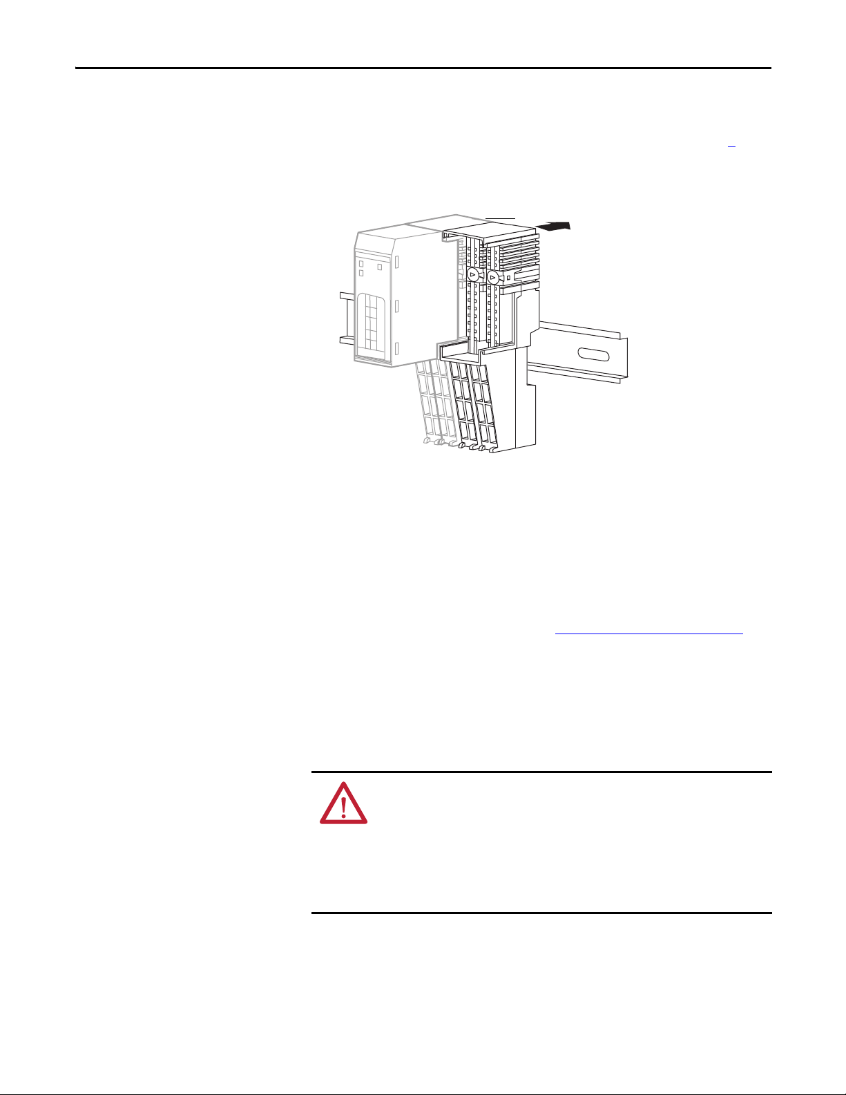
Follow these steps to install the mounting base.
TIP
Slide the mounting base to let the
interlocking side pieces engage
the adjacent module or adapter.
31868-M
Install the Module Chapter 4
1. Position the mounting base as shown in the illustration below step 2
.
2. Slide the mounting base down, allowing the interlocking side pieces to
engage the adjacent module, power supply, or adapter.
3. Press firmly to seat the mounting base on the DIN rail until the mounting
base snaps into place.
In high vibration environments, install slide locks to prevent movement of the
mounting base along the DIN rail.
Refer to the terminal base installation instructions for detailed information on
installation and removal. Always follow instructions and torque specifications in
terminal base installation instructions. See Additional Resources
terminal base installation publications.
Connect the Module to the Mounting Base
Install the module before or after installing the mounting base.
on page 13 for
WARNING: When you insert or remove the module while backplane power is
on, an electrical arc can occur. This could cause an explosion in hazardous
location installations. Be sure that power is removed or the area is
nonhazardous before proceeding.
Repeated electrical arcing causes excessive wear to contacts on both the module
and its mating connector. Worn contacts may create electrical resistance that can
affect module operation.
Rockwell Automation Publication 1734-UM013J-EN-P - July 2014 55

Chapter 4 Install the Module
Mounting Base Assembly
Keyswitch
Lockin g
Mechanism
1. Using a screwdriver, rotate the keyswitches on the mounting base
clockwise until the number required for the type of module aligns with the
notch in the base.
Keep track of which mounting base gets installed on the left and right of
each module.
Cat. No. Key 1 (left) Key 2 (right)
1734-IB8S 8 1
1734-OB8S 8 2
1734-IE4S 8 3
2. Make certain the DIN-rail (orange) locking screw is in the horizontal
position, noting that you cannot insert the module if the mounting-base
locking mechanism is unlocked.
3. Insert the module straight down into the two side-by-side mounting bases
and press to secure, locking the module into place.
Connect the Removable Terminal Block
If a removable terminal block (RTB) is supplied with your mounting base
assembly, you need to remove it by pulling up on the RTB handle. This lets you
remove and replace the base as necessary without removing any of the wiring.
WARNING: When you connect or disconnect the removable terminal block
(RTB) with field-side power applied, an electrical arc can occur. This could cause
an explosion in hazardous location installations. Be sure that power is removed
or the area is nonhazardous before proceeding.
56 Rockwell Automation Publication 1734-UM013J-EN-P - July 2014

Install the Module Chapter 4
Follow these directions to reinsert the RTB.
1. Insert the RTB end opposite the handle into the base unit, noting that this
end has a curved section that engages with the mounting base.
2. Rotate the terminal block into the mounting base until it locks itself in
place.
3. If an I/O module is installed, snap the RTB handle into place on the
module.
Remove a Mounting Base
To remove a mounting base, you must remove any installed module and the
module installed in the base to the right. If the mounting base has a removable
terminal base (RTB), unlatch the RTB handle on the I/O module and pull on the
handle to remove the RTB.
WARNING: When you insert or remove the module while backplane power is
on, an electrical arc can occur. This could cause an explosion in hazardous
location installations. Be sure to remove power or that the area is nonhazardous
before proceeding.
1. Pull up on the I/O module to remove it from the base.
2. Remove the module to the right of the base you are removing, noting that
the interlocking portion of the base sits under the adjacent module.
3. Use a screwdriver to rotate the orange DIN-rail locking screw on the
mounting base to a vertical position, noting this releases the locking
mechanism.
4. Lift the mounting base off the DIN rail.
Rockwell Automation Publication 1734-UM013J-EN-P - July 2014 57

Chapter 4 Install the Module
Wire Modules
Follow these guidelines when wiring the modules.
• Do not route communication, input, or output wiring with conduit
containing high voltage. Refer to the Industrial Automation Wiring and
Grounding Guidelines, publication 1770-4.1
• Wire correctly after confirming the signal names of all terminals.
• Use shielded cable for analog and tachometer inputs.
• When using the sensor power supply on the 1734-IE4S module, do not
connect an external power supply to the sensor.
• If you use the 1734-IE4S module's sensor power supply to power your
input devices, you are responsible for verifying that your application
operates properly with the diagnostic features of this output.
• Tighten screws for communication and I/O connectors correctly.
• When using analog inputs, wire only to voltage or only to current inputs,
not both. Mixing input types may induce noise on the input
measurements.
ATT EN TI ON : Wire the POINT Guard I/O modules properly so that 24V DC line
does not touch the safety outputs accidentally or unintentionally.
Do not connect loads beyond the rated value to safety outputs.
Wire conductors correctly and verify operation of the module before placing the
system into operation. Incorrect wiring may lead to loss of safety function.
Do not apply DC voltages exceeding the rated voltages to the module.
Do not connect a power source to the sensor power supply in the 1734-IE4S
module or you could blow an internal fuse, rendering the module inoperative.
Disconnect the module from the power supply before wiring. Devices connected to
the module may operate unexpectedly if wiring is performed while power is
supplied.
.
WARNING: If you connect or disconnect wiring while the field-side power is
on, an electrical arc can occur. This could cause an explosion in hazardous
location installations. Be sure that power is removed or the area is
nonhazardous before proceeding.
This equipment shall be used within its specified ratings defined by Rockwell
Automation.
ATTENTION: This product is grounded through the DIN rail to chassis ground.
Use zinc plated yellow-chromate steel DIN rail to assure proper grounding. The
use of other DIN rail materials (for example, aluminum or plastic) that can
corrode, oxidize, or are poor conductors, can result in improper or intermittent
grounding. Secure DIN rail to mounting surface approximately every 200 mm
(7.8 in.) and use end-anchors appropriately.
58 Rockwell Automation Publication 1734-UM013J-EN-P - July 2014

Install the Module Chapter 4
I0 I1 I4 I5
I2 I3 I6 I7
COM COM COM COM
TO T1M T2 T3M
0
2
4
6
1
3
5
7
0
2
4
6
1
3
5
7
Where:
T0 = Test Output 0
T1M = Test Output 1 with Muting
T2 = Test Output 2
T3M = Test Output 3 with Muting
I0…I7 = Inputs 0…7
COM = Supply Commo n
1734-TOP and
1734-TB Bases
Shown
1734-TOP and
1734-TB Bases
Shown
Where:
O0…O7 = Safety Outputs 0…7
COM = Supply Commo n
Terminal Layout
Figure 25, Figure 26, and Figure 27 on page 60 show the field wiring connections
for the POINT Guard I/O modules.
Figure 25 - 1734-IB8S Field Connections
Figure 26 - 1734-OB8S Field Connections
O0 O1 O4 O5
0
O2 O3 O6 O7
2
COM COM COM COM
4
COM COM COM COM
6
Rockwell Automation Publication 1734-UM013J-EN-P - July 2014 59
1
3
5
7
0
2
4
6
1
3
5
7
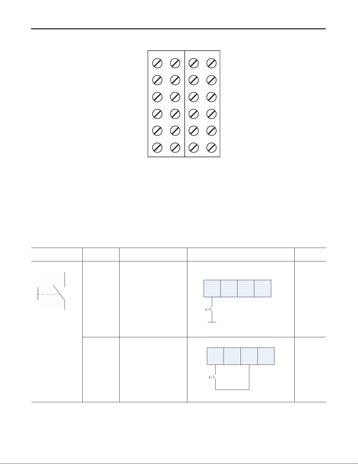
Chapter 4 Install the Module
V0 V1 V2 V3
I0 I1 I2 I3
COM COM COM COM
COM COM COM COM
S0 S1 S2 S3
S0 S1 S2 S3
1734-TOP3 Base
Shown
Where:
V0…V3 = Voltage inputs 0…3
I0…I3 = Current inputs 0…3
COM = S upply Com mon
S0…S3 = Sensor power terminals
I0 I1 T0 T1
24V DC
I0 I1 T0 T1
Figure 27 - 1734-IE4S Field Connections
Connection Details
Connected Device Test Pulse from
Push Button No Connect the push button between 24V
See the tables that show input device connection methods and their safety
categories.
Tes t Ou tput
Yes Connect the push button between I0
Connection Schematic Diagram Safety
DC and I0.
and T0. T0 must be configured as test
pulse.
Category
1
2
60 Rockwell Automation Publication 1734-UM013J-EN-P - July 2014

Install the Module Chapter 4
I0 I1 T0 T1
OSSD2
OSSD1
I0 I1 T0 T1In -
24V
DC
Com
OSSD2
OSSD1
Connected Device Test Pulse from
Tes t Ou tput
Emergency stop button
No Connect the devices between T0 and I0
Door monitoring switch
Yes Connect the device between I0 and T0,
Connection Schematic Diagram Safety
Category
3
and I1, noting that T0 is configured for
24V power supply.
I0 I1 T0 T1
Connect the devices between 24V DC
and I0 and I1.
I0 I1 T0 T1
24V DC
4
and I1 and T1.
Light Curtain Yes Connect the OSSD1 and OSSD2 to I0 and
I1, respectively. Connect the 24V power
supply commons.
light curtain
being used
Rockwell Automation Publication 1734-UM013J-EN-P - July 2014 61
3 or 4 based on

Chapter 4 Install the Module
IO
I2
COM
COM
TO
TO
I1
I3
COM
COM
T1M
T1M
I4
I6
COM
COM
T2
T2
I5
I7
COM
COM
T3M
T3M
1734-TB, 1734-TOP,
1734-TOP3 Bases
Shown
Only with the 1734TOP3 base.
Wiring Examples
Read this section for examples of wiring by application. See catalog number
details for the appropriate module.
Emergency Stop Dual-channel Devices
This example shows wiring and controller configuration when using a digital
POINT Guard I/O module with an emergency stop button and gate monitoring
switch that have dual-channel contacts. When used in combination with the
programs in a safety controller, this wiring is safety Category 4 (emergency stop
button) and safety Category 3 (gate monitoring switch).
Figure 28 - POINT Guard I/O Module Wiring (dual-channel contacts)
Controller
Configuration
Safety Input 0 Safety Input 0 Channel Mode Test Pulse from Test Output
Safety Input 1 Safety Input 1 Channel Mode Test Pulse from Test Output
Safety Input 2 Safety Input 2 Channel Mode S afety Input
Safety Input 3 Safety Input 3 Channel Mode S afety Input
Test Output 0 Test Output 0 Mode Pulse Test Output
Test Output 1 Test Output 1 Mode Pulse Test Output
Test Output 2 Test Output 2 Mode Power Supply Output
Test Output 3 Test Output 3 Mode Power Supply Output
Parameter Name Configuration Setting
Sa fe ty I npu t 0 Test Sour ce Test Outp ut 0
Dual-channel Safety Input 0/1 Mode Dual-channel Equivalent
Dual-channel Safety Input 0/1 Discrepancy Time 100 ms (application dependent)
Sa fe ty I npu t 1 Test Sour ce Test Outp ut 1
Sa fe ty I npu t 2 Test Sour ce Test Outp ut 2
Dual-channel Safety Input 2/3 Mode Dual-channel Equivalent
Sa fe ty I npu t 3 Test Sour ce Test Outp ut 3
62 Rockwell Automation Publication 1734-UM013J-EN-P - July 2014
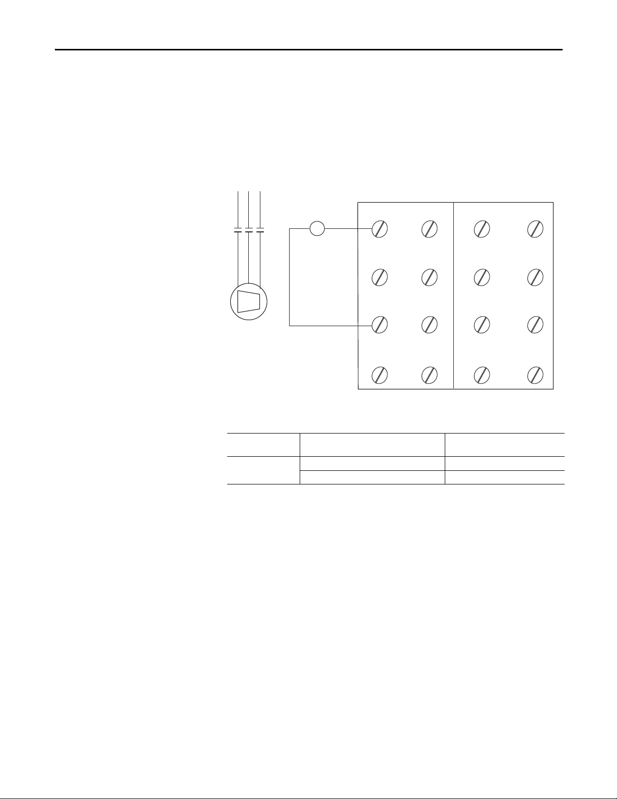
Install the Module Chapter 4
COM COM CO MCOM
COM COM COMCOM
00 01 04 05
02 03 06 07
K1K1
M
Where:
O0…O7 = Safety Outputs
COM = Common
Single-channel Safety Contactor
This example shows wiring and controller configuration when using a digital
POINT Guard I/O module with a single safety contactor.
When used in combination with the programs of the safety controller, this circuit
configuration is safety Category 2.
Figure 29 - POINT Guard I/O Module Wiring (single safety contact)
Controller
Configuration
Safety Output 0 Safety Output 0 Point Mode Safety Pulse Test
Parameter Name Configuration Setting
Point Operation Type Single Channel
Rockwell Automation Publication 1734-UM013J-EN-P - July 2014 63

Chapter 4 Install the Module
Where:
O0…O7 = Safety Outputs
COM = Common
Dual-channel Safety Contactors
This example shows wiring and controller configuration when using a digital
POINT Guard I/O module with redundant safety contactors.
When used in combination with the programs of the safety controller, this circuit
configuration is safety Category 4. Additional wiring, such as monitoring
feedback, may be required to achieve safety Category 4.
Figure 30 - POINT Guard I/O Module Wiring (redundant safety contacts)
00 01 04 05
K1K1
K2K2
02 03 06 07
M
Controller
Configuration
Safety Output 0 Safety Output 0 Point Mode Safety Pulse Test
Safety Output 1 Safety Output 1 Point Mode Safety Pulse Test
Parameter Name Configuration Setting
Point Operation Type Dual-channel
COM COM COMCOM
COM CO M CO MCOM
64 Rockwell Automation Publication 1734-UM013J-EN-P - July 2014

Install the Module Chapter 4
IMPORTANT
IMPORTANT
Safety Analog Input Wiring
The following sections contain important guidelines for wiring safety analog
inputs and wiring examples for the 1734-IE4S module.
Guidelines for Wiring Safety Analog Inputs
Follow these guidelines when wiring your safety analog inputs.
For 8 terminal connections, either the 1734-TOP or 1734-TB terminal base can
be used. For all 12 terminal connections, only the 1734-TOP3 base can be used.
When using a 1734-TOP3 base, both of the COM terminals and both of the
Sensor Power terminals for each channel are internally connected. The FE
terminal connection shown on the diagrams represents a grounding lug on the
panel or terminal connection to the DIN rail.
If the sensor has a digital output for use with Tachometer mode, it must be either
a push-pull type output or have appropriate pull-up or pull-down resistors for
NPN or PNP sensors The analog input module does not provide the low
impedance of these pull-up or pull-down resistors.
See Figure 43
and Figure 44 on page 72 for examples.
You must verify the behavior of your 3-wire sensor to make sure that if it loses
its ground connection, the signal is 0 (safe state) at the module input when the
fault occurs.
To obtain SIL 3, Cat. 3 or Cat.4, you must make sure that the analog input
signals cannot short together or that the two sensors are installed to provide
signals that are offset from one another. When the module is configured as the
source for sensor power, a short-circuit is detected at powerup (Cat. 2).
However, when an external power supply is used, this fault must be detected
by another means.
Rockwell Automation Publication 1734-UM013J-EN-P - July 2014 65

Chapter 4 Install the Module
V0 V1 V2 V3
I0 I1 I2 I3
COM COM COM COM
S0
FE
S1 S2 S3
SIL2 or SIL 3
2-wire
Sensor
1734-TB Terminal Bases
Signal (I)
+24V
Cable Shield
For analog voltage-output sensors, the signal levels for operation for the application must be outside the signal level when the signal is not
present, for example, when the wire is broken.
See Figure 43
and Figure 44 on page 72 for tachometer wiring detail.
SIL 2
3-wire
Sensor
1734-TB Terminal Bases
Signal (V)
+24V
Cable Shield
Signal Return
Safety Analog Input Wiring Examples
Figure 31 - 2-wire Current (4…20 mA) Sensor (SIL2 or SIL 3)
Figure 32 - 3-wire Voltage or Tachometer Sensor (SIL 2)
V0 V1 V2 V3
I0 I1 I2 I3
COM COM COM COM
S0
Follow the Guidelines for Wiring Safety Analog Inputs on page 65.
S1 S2 S3
FE
66 Rockwell Automation Publication 1734-UM013J-EN-P - July 2014

Figure 33 - 3-wire Current Sensor (SIL 2)
For 0…20 mA analog current-output sensors, the signal levels for operation for the application must be outside the signal level when the signal
is not present, for example, when the wire is broken.
SIL 2
3-wire
Sensor
1734-TB Terminal Bases
Signal (I)
+24V
Cable Shield
Signal Return
FE
V0 V1 V2 V3
I0 I1 I2 I3
COM COM COM COM
COM COM COM COM
S0 S1 S2 S3
S0 S1 S2 S3
Signal Return and Common are at the same potential.
See Figure 43
and Figure 44 on page 72 for tachometer wiring detail.
SIL 2
4-wire
Sensor
1734-TOP3 Terminal Bases
Signal (V)
+24V
Cable Sh ield
Signal Return
Common
Install the Module Chapter 4
V0 V1 V2 V3
I0 I1 I2 I3
COM COM COM COM
Figure 34 - 4-wire Voltage or Tachometer Sensor (SIL 2)
S0
S1 S2 S3
FE
Follow the Guidelines for Wiring Safety Analog Inputs on page 65.
Rockwell Automation Publication 1734-UM013J-EN-P - July 2014 67

Chapter 4 Install the Module
FE
V0 V1 V2 V3
I0 I1 I2 I3
COM COM COM COM
COM COM COM COM
S0 S1 S2 S3
S0 S1 S2 S3
Signal Return and Common are at the same potential.
SIL 2
4-wire
Sensor
1734-TOP3 Terminal Bases
Signal (I)
+24V
Cable Sh ield
Signal Return
Common
Field sensors are monitoring the same signal in a redundant configuration.
You must configure a safety deadband between the two signals to achieve SIL 3.
SIL 2
2-wire
Sensor
1734-TB Terminal Bases
Signal (I)
+24V
Cable Shield
Cable Shield
+24V
SIL 2
2-wire
Sensor
Signal (I)
Figure 35 - 4-wire Current Sensor (SIL 2)
Figure 36 - 2-wire Current (4…20 mA) Sensor (SIL 3)
V0 V1 V2 V3
I0 I1 I2 I3
COM COM COM COM
S0
Follow the Guidelines for Wiring Safety Analog Inputs on page 65.
S1 S2 S3
FE
FE
68 Rockwell Automation Publication 1734-UM013J-EN-P - July 2014
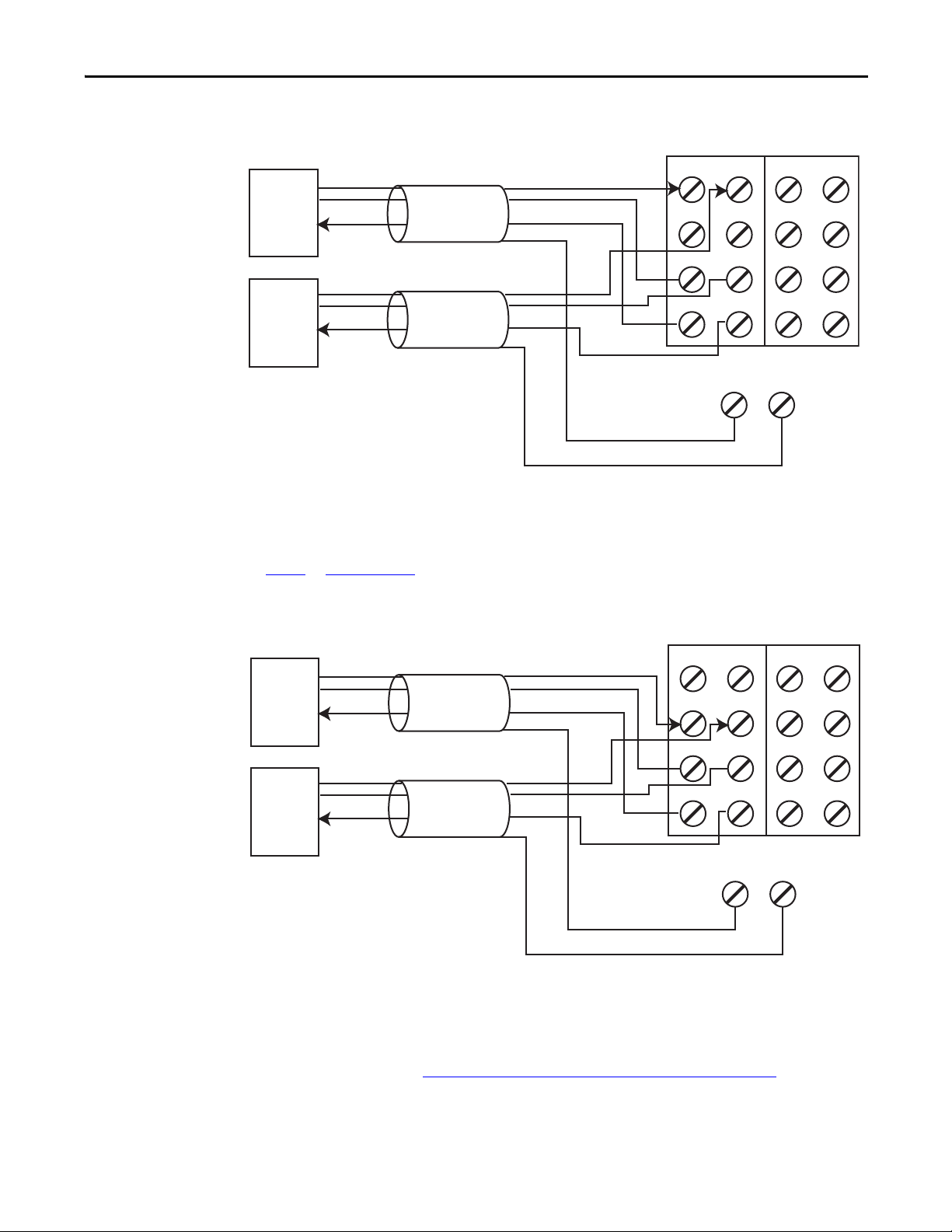
Figure 37 - 3-wire Voltage or Tachometer Sensor (SIL 3)
This wiring configuration may also be used for SIL 2 redundant Tachometer mode.
For analog voltage-output sensors, the signal levels for operation for the application must be outside the signal level when the signal is not
present, for example, when the wire is broken.
Field sensors are monitoring the same signal in a redundant configuration.
You must configure a safety discrepancy deadband between the two signals to achieve SIL 3.
SIL 2
3-wire
Sensor
1734-TB Terminal Bases
Signal (V)
+24V
Cable Shield
Cable Shield
+24V
SIL 2
3-wire
Sensor
Signal (V)
Signal Return
Signal Return
See Figure 43
and Figure 44 on page 72 for tachometer wiring detail.
V0 V1 V2 V3
I0 I1 I2 I3
COM COM COM COM
S0
FE
S1 S2 S3
FE
For 0…20 mA analog current-output sensors, the signal levels for operation for the application must be outside the signal level when the signal
is not present, for example, when the wire is broken.
Field sensors are monitoring the same signal in a redundant configuration.
You must configure a safety discrepancy deadband between the two signals to achieve SIL 3.
SIL 2
3-wire
Sensor
1734-TB Terminal Bases
Signal (I)
+24V
Cable Shield
Cable Sh ield
+24V
SIL 2
3-wire
Sensor
Signal (I)
Signal Return
Signal Return
Install the Module Chapter 4
V0 V1 V2 V3
I0 I1 I2 I3
COM COM COM COM
Figure 38 - 3-wire Current Sensor (SIL 3)
S0
S1 S2 S3
FE
FE
Follow the Guidelines for Wiring Safety Analog Inputs on page 65.
Rockwell Automation Publication 1734-UM013J-EN-P - July 2014 69
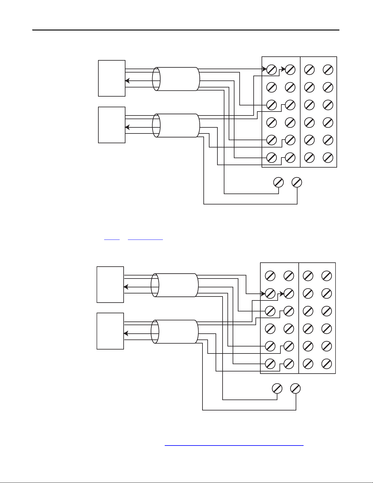
Chapter 4 Install the Module
This wiring configuration may also be used for SIL 2 redundant Tachometer mode.
Signal Return and Common are at the same potential.
Field sensors are monitoring the same signal in a redundant configuration.
You must configure a safety discrepancy deadband between the two signals to achieve SIL 3.
SIL 2
4-wire
Sensor
1734-TOP3 Terminal Bases
Signal (V)
+24V
Cable Shield
Signal Return
Common
SIL 2
4-wire
Sensor
Signal (V)
+24V
Signal Return
Common
Cable Sh ield
See Figure 43 and Figure 44 on page 72 for tachometer wiring detail.
FE FE
V0 V1 V2 V3
I0 I1 I2 I3
COM COM COM COM
COM COM COM COM
S0 S1 S2 S3
S0 S1 S2 S3
Signal Return and Common are at the same potential.
Field sensors are monitoring the same signal in a redundant configuration.
You must configure a safety discrepancy deadband between the two signals to achieve SIL 3.
SIL 2
4-wire
Sensor
1734-TOP3 Terminal Bases
Signal (I)
+24V
Cable Shield
Signal Return
Common
SIL 2
4-wire
Sensor
Signal (I)
+24V
Signal Return
Common
Cable Shield
Figure 39 - 4-wire Voltage or Tachometer Sensor (SIL 3)
V0 V1 V2 V3
I0 I1 I2 I3
COM COM COM COM
S0 S1 S2 S3
COM COM COM COM
S0 S1 S2 S3
FE FE
Figure 40 - 4-wire Current Sensor (SIL 3)
Follow the Guidelines for Wiring Safety Analog Inputs on page 65.
70 Rockwell Automation Publication 1734-UM013J-EN-P - July 2014

Install the Module Chapter 4
IMPORTANT
V0
DC
V1 V2 V3
I0 I1 I2 I3
COM COM COM COM
S0
FE
S1 S2 S3
+
-
Signal Return and Common are at the same potential.
1734-TB Terminal Bases
Signal (V)
+24V
Cable Sh ield
Signal Return
4-wire
Sensor
See Figure 43
and Figure 44 on page 72 for tachometer wiring detail.
V0
DC
V1 V2 V3
I0 I1 I2 I3
COM COM COM COM
S0
FE
S1 S2 S3
+
-
Signal Return and Common are at the same potential.
1734-TB Terminal Bases
Signal (V)
+24V
Cable Shield
Signal Return
4-wire
Sensor
In the following two examples, the negative terminal of the sensor power supply
and that of the 1734 terminal base COMMON must be at the same potential.
Use of an external power supply limits diagnostics and increases susceptibility to
noise.
You are responsible for making sure that the sensor is receiving appropriate
power. Safety sensors that are not properly powered may not deliver accurate
signals to the analog input module.
Follow the Guidelines for Wiring Safety Analog Inputs
on page 65.
Figure 41 - 4-wire Voltage or Tachometer Sensor (SIL 2) with External Power Supply
Figure 42 - 4-wire Current Sensor (SIL 2) with External Power Supply
Rockwell Automation Publication 1734-UM013J-EN-P - July 2014 71

Chapter 4 Install the Module
Sinking Sensor
(NPN-type)
1734-TOP3 Terminal Bases
Metal Oxide or
Carbon
Composition
1k
2W
25
20
15
10
5
0
Edge-to-edge Time
Measured Here
1734-IE4S with Trigger = Falling Edge
Transistor Pull-down
Resistor Pull-up
Electronics
V0 V1 V2 V3
I0 I1 I2 I3
COM COM COM COM
COM COM COM COM
S0 S1 S2 S3
S0 S1 S2 S3
1734-TOP3 Terminal Bases
Sourcing Sensor
(PNP-type)
Metal Oxide or
Carbon
Composition
1k
2W
25
20
15
10
5
0
Edge-to-edge Time
Measured Here
1734-IE4S with Trigger = Rising Edge
Resistor Pulldown
Transistor
Pull-up
Electronics
Figure 43 - Safety Analog Input Wiring for Sinking Tachometer Sensor
V0 V1 V2 V3
I0 I1 I2 I3
COM COM COM COM
S0 S1 S2 S3
COM COM COM COM
S0 S1 S2 S3
Figure 44 - Safety Analog Input Wiring for Sourcing Tachometer Sensor
72 Rockwell Automation Publication 1734-UM013J-EN-P - July 2014
Follow the Guidelines for Wiring Safety Analog Inputs on page 65.

Chapter 5
IMPORTANT
TIP
Configure the Module in a GuardLogix Controller
System
Top ic Pag e
Setting Up the Module 73
Add and Configure the Ethernet Bridge Module 74
Add and Configure the 1734 Ethernet Adapter 74
Add and Configure Safety Digital Input Modules 77
Add and Configure Safety Digital Output Modules 86
Add and Configure Safety Analog Input Modules 91
Values and States of Tags 100
Configure Safety Connections 102
Configuration Ownership 103
Saving and Downloading the Module Configuration 104
Setting Up the Module
When using a GuardLogix controller on an EtherNet/IP network, configure the
POINT
At the bottom of each dialog box, click Help for information about how to
complete entries in that dialog box. At the bottom of warning dialog boxes, click
Help for information about that specific error.
When first setting up your POINT Guard I/O modules on an EtherNet/IP
network, perform the following steps.
Guard I/O modules by using the Logix Designer application.
Yo u must configure each point that is to be used as a safety input or output.
By default, all safety input and output points are disabled.
If you need an add-on profile, visit the My Support website at
http://support.rockwellautomation.com/ControlFLASH/LogixProfiler.asp.
1. Add and Configure the Ethernet Bridge Module
2. Add and Configure the 1734 Ethernet Adapter
3. Add and Configure Safety
4. Add and Configure Safety Digital Output Modules
5.
Add and Configure Safety Analog Input Modules
Digital Input Modules.
.
.
.
Rockwell Automation Publication 1734-UM013J-EN-P - July 2014 73

Chapter 5 Configure the Module in a GuardLogix Controller System
Add and Configure the Ethernet Bridge Module
Follow this procedure to add and configure the Ethernet bridge module. In this
example, we use a 1756 GuardLogix controller.
1. From the I/O Configuration tree, right-click 1756 Backplane, 1756-Axx
and choose New Module.
2. In the Select Modules dialog box, check Communication and
Allen-Bradley.
3. Choose an Ethernet module from the list and click Create.
In this example, we chose the 1756-EN2T bridge module. CIP Safety is
supported by these module revisions.
Cat. No. Compatible Major Revision
1756-EN2F 1 or later
1756-EN2T 1 or later
1756-ENBT 3 or later
1756-EN2TR 3 or later
1756-EN3TR 3 or later
1768-ENBT 3 or later
4. Specify the properties for the new module.
a. In the Name field of the New Module dialog box, type the name of the
Ethernet bridge module.
b. In the Description field, type an optional description.
c. In the IP Address field, type the IP address.
d. In the Slot field, choose the slot number.
74 Rockwell Automation Publication 1734-UM013J-EN-P - July 2014

Configure the Module in a GuardLogix Controller System Chapter 5
5. Click Change to edit the Module Definition.
a. In the Revision fields, choose the major and minor revisions.
b. From the Electronic Keying pull-down menu, choose the appropriate
keying method.
Choose Description
Compatible Module Allows a module to determine whether it can emulate the module
Disable Keying None of the parameters in the physical module and module
Exact Match All of the parameters must match or the inserted module rejects a
defined in the configuration sent from the controller.
configured in the software must match.
Do not choose Disable Keying.
connection to the controller.
6. Click OK.
The I/O Configuration tree displays the Ethernet connection.
Add and Configure the 1734 Ethernet Adapter
1. Right-click the Ethernet connection and choose New Module.
2. On the Select Module dialog box, check Communication and
Allen-Bradley.
3. Choose an Ethernet adapter from the list and click Create.
Rockwell Automation Publication 1734-UM013J-EN-P - July 2014 75

Chapter 5 Configure the Module in a GuardLogix Controller System
IMPORTANT
4. Specify the general properties of the Ethernet adapter.
a. In the Name field of the New Module dialog box, type the name of the
1734 Ethernet adapter.
b. In the Description field, type a description, if desired.
c. In the IP Address field, type the IP address.
5. Click Change to edit the Ethernet Adapter’s Module Definition.
.
a. In the Revision fields, choose the major and minor revisions.
1734-AENT adapter firmware must be major revision 3 or later to
support POINT Guard I/O modules.
b. From the Electronic Keying pull-down menu, choose the appropriate
keying method.
Choose Description
Exact Match Module and type series must exactly match or the module will be rejected by the
Compatible Module Controller will check module type and revision for compatibility. Compatible
Disable Keying Controller will check module type, but will accept any version. Do not choose
controller.
modules that match or are newer will be accepted.
Disable Keying.
76 Rockwell Automation Publication 1734-UM013J-EN-P - July 2014
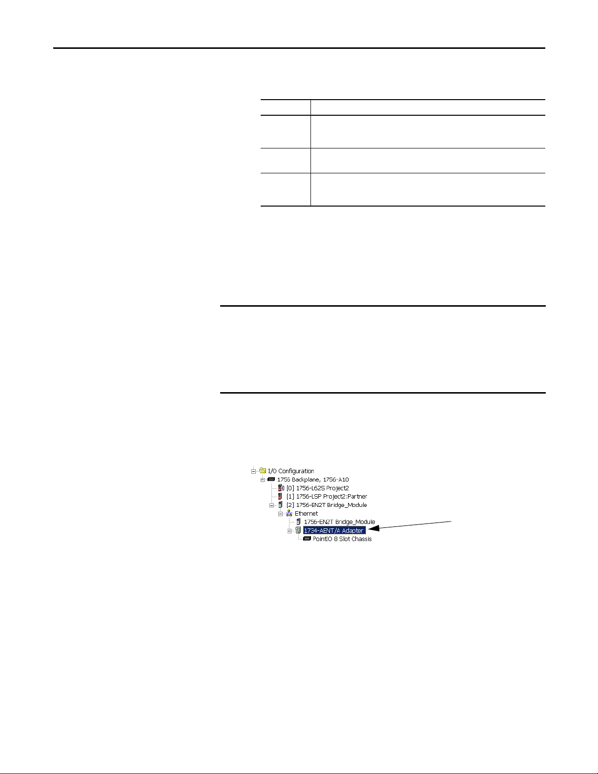
Configure the Module in a GuardLogix Controller System Chapter 5
TIP
IMPORTANT
c. From the Connection pull-down menu, choose the appropriate
connection for the 1734 Ethernet adapter.
Choose Description
Listen Only Read or verify standard digital I/O data only, but does not control the modules.
None The adapter makes a direct connection to each of the module’s listed under the
Rack
Optimization
(When you have multiple controllers, one controller is used to control and the other
controllers are used to monitor.)
1734-AENT adapter in the I/O Configuration tree.
Standard digital I/O data is collected into a single rack image.
POINT specialty, analog, or safety (POINT Guard I/O) modules do not use
rack optimization.
If there are no standard digital I/O modules in your POINT I/O
system, choose None.
d. From the Chassis Size pull-down menu, choose the number of
POINT I/O modules that will be attached to the 1734 Ethernet
adapter plus 1 for the 1734 Ethernet adapter.
Do not count terminal bases. Enter only the number of physical modules
installed, plus 1 for the adapter. This number must match exactly. You cannot
enter a higher number anticipating future expansion.
Each POINT Guard module you configure may consume up to 2 connections of
the 20 connection limit within the 1734-AENT or 1734-AENTR modules. Be
sure you are aware of and design your POINT system with these limits in mind.
Add and Configure Safety Digital Input Modules
6. Click OK to return to the Module Properties dialog box.
7. Click OK again to apply your changes.
The I/O Configuration tree displays the 1734 Ethernet adapter.
To include a safety digital input module in the project, you add the module under
the I/O chassis in the I/O Configuration tree, configure the module’s general
properties, configure the digital inputs, and then configure test outputs as
described in the following sections.
Add the Safety Digital Input Module
Follow these steps to add the POINT Guard I/O safety digital input module.
Rockwell Automation Publication 1734-UM013J-EN-P - July 2014 77

Chapter 5 Configure the Module in a GuardLogix Controller System
1. Right-click the POINT I/O Chassis and choose New Module.
2. From the Select Module dialog box, check Digital and Allen-Bradley.
3. Select an input module and click Create.
4. Specify the module’s general properties.
a. In the Name field of the New Module dialog box, type a unique name
for the input module.
78 Rockwell Automation Publication 1734-UM013J-EN-P - July 2014

Configure the Module in a GuardLogix Controller System Chapter 5
b. From the Module Number pull-down menu, choose a unique module
number that corresponds to the module’s position in the chassis.
c. In the Description field, type a description, if desired.
d. In the Safety Network Number field, use the default setting.
For a detailed explanation of the safety network number (SNN), see the
GuardLogix Controller Systems Safety Reference Manuals listed in the
Additional Resources on page 13
, noting that in most cases, you use the
default provided by the Logix Designer application.
The purpose of the safety network number (SNN) is to make sure that
every module in a system can be uniquely identified. We suggest that all
safety modules on a network have the same SNN, to make
documentation easier. During configuration, the Logix Designer
application defaults a safety device’s SNN to match the SNN of the
lowest safety node on each network.
5. Click Change to edit the Module Definition.
a. In the Series field, choose the input module’s series letter.
b. In the Revision fields, choose the input module’s revision numbers.
c. From the Electronic Keying pull-down menu, choose the appropriate
keying method for the input module.
Choose Description
Exact Match All of the parameters must match or the inserted module rejects a connection to
Compatible
Module
the controller.
Allows an I/O module to determine whether it can emulate the module defined in
the configuration sent from the controller.
d. From the Configured By pull-down menu, choose the appropriate
method by which this module is configured.
Choose Description
This Cont roller This s election d irects the co ntroller to con figure the mo dule.
External Means This selection directs the controller to establish a safety input connec tion only,
and the controller will not configure the module or control the Test Outputs.
Rockwell Automation Publication 1734-UM013J-EN-P - July 2014 79

Chapter 5 Configure the Module in a GuardLogix Controller System
IMPORTANT
e. From the Input Data pull-down menu, choose Safety or None.
Choose Description
Safety These tags are created for the target module:
• RunMode for module mode
• ConnectionFaulted for communication status
• Safety Data for safety inputs from the module
f. From the Output Data pull-down menu, choose from the following
options.
Choose Description
None Results in an input only connec tion to the module. Inputs and status are read, but no
(1)
Tes t
(1) To have this choice from the pull-down menu, you must choose ‘This Controller’ from the Configured By pull-down
menu.
outputs are written. You can still use the test outputs as pulse test outputs or a power
supply. If you are not controlling the module’s test outputs via application logic, this is
the recommended setting.
Creates these tags to enable application logic control of the test outputs on the module.
This selection allows the test outputs to be used as standard outputs and muting
outputs.
When test outputs are configured as standard outputs, they
must not be used for safety purposes.
80 Rockwell Automation Publication 1734-UM013J-EN-P - July 2014

Configure the Module in a GuardLogix Controller System Chapter 5
g. From the Input Status pull-down menu, choose from the following
options.
Choose Description
None There are no status tags.
Pt. Status There is one status tag for each input point.
Combined Status Muting
Pt. Status - Muting There is a muting status tag for test output T1 and T3 with point status for each
Pt. Status-Muting-Test
Output
• A single BOOL tag represents an AND of the status bits for all the input
points. For example, if any input channel has a fault, this bit goes LO.
• A single BOOL tag represents the Input Power Status (error bit) from the
input assembly.
• A muting status tag for test output T1 and T3.
input point.
• Status tags for each of the input points.
• Muting status tag for test output T1 and T3.
• Status tags for each of the test outputs.
(1)
(1) When using combined status, use explicit messaging to read individual point status for diagnostic purposes.
h. From the Data Format pull-down menu, use the default ‘Integer’.
Rockwell Automation Publication 1734-UM013J-EN-P - July 2014 81

Chapter 5 Configure the Module in a GuardLogix Controller System
2 3 4
5
6
7
6. Click OK to return to the Module Properties dialog box.
7. Click OK again to apply your changes.
Configure the Safety Digital Inputs
Follow this procedure to configure the safety digital inputs.
1. From the Module Properties dialog box, click the Input Configuration tab.
The I/O Configuration tree displays the module.
82 Rockwell Automation Publication 1734-UM013J-EN-P - July 2014

Configure the Module in a GuardLogix Controller System Chapter 5
IMPORTANT
2. Assign the Point Operation Type.
Choose Description
Single Inputs are treated as single channels.
Dual-channel safety inputs can be configured as two individual single channels.
This does not affect pulse testing because it is handled on an individual channel
basis.
IMPORTANT: Use single-channel mode when you intend to use the GuardLogix
safety application instruc tions.
Equivalent Inputs are treated as a dual-channel pair. The channels must match within the
Complementary Input are treated as a dual-channel pair. They must be in opposite states within
discrepancy time or an error is generated.
the discrepancy time or an error is generated.
When you choose Equivalent or Complementary, you must also assign a
Discrepancy Time.
A discrepancy time setting of 0 ms means that the channels in a dual
configuration can be discrepant for an infinite amount of time without a
fault being declared.
For a discrepancy time setting of 0 ms, the evaluated status of the inputs
still goes to the safe state due to a ‘cycle inputs’ required condition.
However, with a 0 ms discrepancy time setting, a fault is not declared.
A ‘cycle inputs’ required condition occurs when one input terminal goes
from its normal Active->Inactive->Active state while the other input
terminal remains in its normal Active state. Even though no fault is
declared, the inputs must be cycled through the safe state before the
evaluated status of the inputs can return to the Active state. When in a
‘cycle inputs’ required condition, the logical state does not necessarily
match the voltage at the terminals.
Configuring discrepancy time on safety I/O modules masks input
discrepancies detected by the controller safety instructions. Status can
be read by the controller to obtain this fault information.
Rockwell Automation Publication 1734-UM013J-EN-P - July 2014 83

Chapter 5 Configure the Module in a GuardLogix Controller System
3. Assign the Point Mode.
4. Assign a Test Source for each safety input on the module you want to pulse
Choose Description
Not Used The input is disabled. It remains logic 0 if 24V is applied to the input
Safety Pulse Test Pulse testing is performed on this input circuit. A test source on the
Safety A safety input is connected but there is no requirement for the POINT
Standard A standard device, such as a reset switch, is connected. This point
terminal.
POINT Guard I/O module must be used as the 24V source for this
circuit. The test source is configured by using the test source
pull-down menu. The pulse test will detect shor ts to 24V and
channel-to-channel shorts to other inputs.
Guard I/O module to perform a pulse test on this circuit. An example
is a safety device that performs it s own pulse tests on the input wires,
such as a light curtain.
cannot be used in dual-channel operation.
test.
Choose Description
None
Tes t O ut put 0
Tes t O ut put 1
Tes t O ut put 2
Tes t O ut put 3
(1)
(1)
If pulse testing is performed on an input point, then the test source
that is sourcing the 24V for the input circuit must be selected.
If the incorrect test source is entered, the result is pulse test failures
on that input circuit.
(1) Test Output 1 and 3 incorporate optional muting functionality.
5. Assign the Input Delay Time, Off -> On (0…126 ms, in increments of
6ms).
Filter time is for OFF to ON transition. Input must be high after input
delay has elapsed before it is set logic 1. This delay time is configured per
channel with each channel specifically tuned to match the characteristics
of the field device, for maximum performance.
6. Assign the Input Delay Time, Off -> On (0…126 ms, in increments of
6ms).
Filter time is ON to OFF transition. Input must be low after input delay
has elapsed before it is set logic 0. This delay time is configured per channel
with each channel specifically tuned to match the characteristics of the
field device, for maximum performance.
84 Rockwell Automation Publication 1734-UM013J-EN-P - July 2014

Configure the Module in a GuardLogix Controller System Chapter 5
7. From the Input Error Latch Time field, enter the time the module holds an
error to make sure the controller can detect it (0…65,530 ms, in increments
of 10 ms - default 1000 ms).
This setting provides more reliable diagnostics. The purpose for latching
input errors is to make sure that intermittent faults that may exist only for a
few milliseconds are latched long enough to be read by the controller. The
amount of time to latch the errors should be based on the RPI, the safety
task watchdog, and other application-specific variables.
8. Click Apply.
Configure the Test Outputs
Follow this procedure to complete the test output configuration.
1. From the Module Properties dialog box, click the Test Output tab.
2. Assign the Point Mode.
Choose Description
Not Used The test output is disabled (default for T2 and T3).
Standard The test output point can be controlled programmatically by the GuardLogix
Pulse Test The test output is being used as a pulse test source (default for T0 and T1).
Power Supply A constant 24V is placed on the output terminal. It can be used to provide
Muting Lamp Output
(terminals T1 and T3
only)
controller.
power to a field device.
An indicator lamp is connected to the output. When this lamp is energized, a
burned-out bulb, broken wire, or short to GND error condition can be detected.
Typically, the lamp is an indicator used in light curtain applications.
There is also a Test Output Fault Action parameter that can only be read or
written to via explicit messaging. If communication to the module times
out, you can set the test outputs to Clear OFF (default) or Hold Last State.
For more information, see Appendix B
.
3. Click Apply.
Rockwell Automation Publication 1734-UM013J-EN-P - July 2014 85

Chapter 5 Configure the Module in a GuardLogix Controller System
Add and Configure Safety Digital Output Modules
To include a POINT Guard safety digital-output module in the project, you add
the module to the PointIO Chassis configure the module’s general properties,
and configure the digital outputs as described in the following sections.
Add the Safety Digital Output Module
Follow these steps to add the POINT Guard I/O safety digital output module.
Follow these steps to add and configure POINT Guard I/O safety modules.
1. Right-click the POINT I/O Chassis and choose New Module.
2. On the Select Module dialog box, select a safety output module and
click OK.
86 Rockwell Automation Publication 1734-UM013J-EN-P - July 2014

Configure the Module in a GuardLogix Controller System Chapter 5
3. Specify the module’s general properties.
a. In the Name field of the New Module dialog box, type a unique name
for the output module.
b. From the Module Node pull-down menu, choose a unique module
node number that corresponds to the module’s position in the chassis.
c. In the Description field, type a description, if desired.
d. In the Safety Network Number field, use the default setting.
For a detailed explanation of the safety network number (SNN), see the
GuardLogix Controller Systems Safety Reference Manuals listed in the
Additional Resources on page 13
, noting that in most cases, you use the
default provided by the Logix Designer application.
4. Under Module Definition, click Change to edit the module’s settings.
a. In the Series field, choose the output module’s series letter.
b. In the Revision fields, choose the output module’s revision numbers.
Rockwell Automation Publication 1734-UM013J-EN-P - July 2014 87

Chapter 5 Configure the Module in a GuardLogix Controller System
c. From the Electronic Keying pull-down menu, choose the appropriate
keying method from the following options.
Choose Description
Exact Match All of the parameters must match or the inserted module rejects a
connection to the controller.
Compatible Module Lets an I/O module determine whether it can emulate the module defined
in the configuration sent from the controller.
d. From the Configured By pull-down menu, choose the method by
which this module is configured.
Choose Description
This Controller This selection directs the controller to configure and control the safety
outputs.
The Output Data selection will be set to Safety.
External Means This selection directs the controller to establish a safety input connection
only, and the controller will not configure the module or be able to control
the safety outputs.
The Output Data selection will be set to None.
e. From the Input Data pull-down menu, choose None.
None is the only valid selection, as this is an output-only safety module.
f. From the Output Data pull-down menu, choose from the following :
Choose Description
Safety Automatically selected when Configured By = This controller. Results in an output
None Automatically selec ted when Configured By = External. Selecting None results in an
connection. Selecting Safety creates output tags and enables these output s for use in the
Safety Task.
input only connection to the module. Status is read, but no outputs are written.
88 Rockwell Automation Publication 1734-UM013J-EN-P - July 2014

Configure the Module in a GuardLogix Controller System Chapter 5
g. From the Input Status pull-down menu, choose from the following.
Choose Description
None There are no status tags, only data for the outputs.
Pt. Status There is one status tag for each output point.
Pt. Status - Readback • There is one status tag for each output point.
Combined Status Readback - Power
• There is one data tag for the output readback.
• A single BOOL tag represents an AND of the status bits for all the output
points. For example, if any output channel has a fault, this bit goes LO.
• There is one data tag for the output readback.
• A single BOOL tag represents the Output Power Status (error bit) from the
input assembly.
(1)
(1) When using combined status, use explicit messaging to read individual point status for diagnostic purposes.
h. From the Data Format pull-down menu, use the default ‘Integer’.
5. Click OK to return to the Module Properties dialog box.
Rockwell Automation Publication 1734-UM013J-EN-P - July 2014 89

Chapter 5 Configure the Module in a GuardLogix Controller System
6. Click OK again to apply your changes.
Configure the Safety Digital Outputs
Follow this procedure to configure the safety digital outputs.
1. From the Module Properties dialog box, click the Output Configuration
The I/O Configuration tree displays the 1734-OB8S module.
tab.
2. Assign the Point Operation Type.
Choose Description
Single The output is treated as a single channel.
Dual (default) The POINT Guard I/O module treats the outputs as a pair. It always sets them HI or LO as a
matched pair. Safety logic must set both of these outputs ON or OFF at the same time or
the module declares a channel fault.
3. Assign the Point Mode.
Choose Description
Not Used The output is disabled.
Safety The output point is enabled and does not perform a pulse test on the output.
Safety Pulse
Tes t
90 Rockwell Automation Publication 1734-UM013J-EN-P - July 2014
The output point is enabled and performs a pulse test on the output. When the output is
energized, the output pulses low briefly. The pulse test detects whether the output is
functioning properly.

Configure the Module in a GuardLogix Controller System Chapter 5
4. In the Output Error Latch Time field, enter the time the module holds an
error to make sure the controller can detect it (0…65,530 ms, in increments
of 10 ms - default 1000 ms).
This provides more reliable diagnostics. The purpose for latching output
errors is to make sure that intermittent faults that may exist only for a few
milliseconds are latched long enough to be read by the controller. The
amount of time to latch the errors is based on the RPI, the safety task
watchdog, and other application-specific variables.
5. Click Apply.
Add and Configure Safety Analog Input Modules
To include a POINT Guard safety analog input module in the project, you add
the module to the PointIO Chassis, configure the module’s general properties,
and configure the analog inputs as described in the following sections.
Add the Safety Analog Input Module
Follow these steps to add the POINT Guard I/O safety analog input module.
1. Right-click the POINT I/O Chassis and choose New Module.
2. From the Select Module dialog box, select an analog input module and
click Create.
Rockwell Automation Publication 1734-UM013J-EN-P - July 2014 91

Chapter 5 Configure the Module in a GuardLogix Controller System
3. Specify the module’s general properties.
a. In the Name field of the New Module dialog box, type a unique name
for the analog input module.
b. From the Module Number pull-down menu, choose a unique module
number that corresponds to the module’s position in the chassis.
c. In the Description field, type a description, if desired.
d. In the Safety Network Number field, use the default setting.
For a detailed explanation of the safety network number (SNN), see the
GuardLogix Controller Systems Safety Reference Manuals listed in the
Additional Resources on page 13
, noting that in most cases, you use the
default provided by the Logix Designer application.
The safety network number (SNN) is a unique number that identifies a
safety subnet. We suggest that all safety modules on a network have the
same SNN, to make documentation easier. During configuration, the
Logix Designer application defaults a safety device’s SNN to match the
SNN of the lowest safety node on the network.
4. Click Change to open the Module Definition dialog box.
a. In the Series field, choose the analog input module’s series letter.
b. In the Revision fields, choose the module’s revision numbers.
92 Rockwell Automation Publication 1734-UM013J-EN-P - July 2014

Configure the Module in a GuardLogix Controller System Chapter 5
c. From the Electronic Keying pull-down menu, choose the appropriate
keying method for the input module.
Choose Description
Exact Match All of the parameters must match or the inserted module rejects a connection to
Compatible
Module
the controller.
Allows an I/O module to determine whether it can emulate the module defined in
the configuration sent from the controller.
d. From the Configured By pull-down menu, choose the appropriate
method by which this module is configured.
Choose Description
This Cont roller This s election d irects the co ntroller to con figure the In puts.
External Means This selection directs the controller to establish a safety input connec tion only,
and the controller will not configure the module.
e. From the Input Data pull-down menu, choose Safety.
f. From the Output Data pull-down menu, choose from the following.
Choose Description
None An output tag is not generated.
Safety-Tachometer This option is available when the Configured By selection is This Controller. The
output tag contains data members for safety output data needed for
Tachometer mode. If you are using Tachometer mode, you must choose this
setting; otherwise, you will not be able to configure other Tachometer
parameters.
g. From the Process Data pull-down menu, choose from the following.
Choose Description
Status The input tag contains safety analog input data from the module.
Status - Alarms These tags are created for the target module:
Status - Alarms - Faults These tags are created for the target module:
• Safety data for individual process alarms
• Safety data for safety analog inputs from the module
• Safety data for individual process alarms
• Safety data for faults
• Safety data for safety analog inputs from the module
h. From the Data Format pull-down menu, use the default ‘Integer’.
5. Click OK to return to the Module Properties dialog box.
6. Click OK again to apply your changes.
The I/O Configuration tree displays the 1734-IE4S module.
Rockwell Automation Publication 1734-UM013J-EN-P - July 2014 93
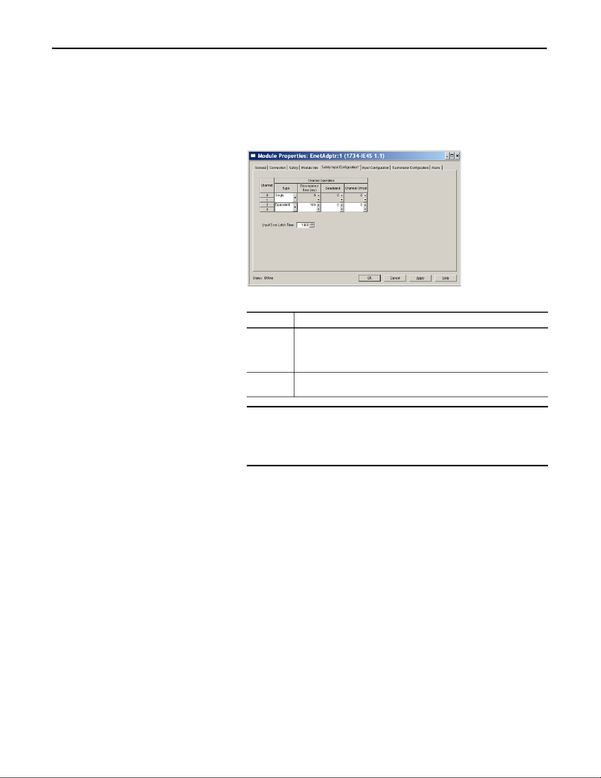
Chapter 5 Configure the Module in a GuardLogix Controller System
IMPORTANT
TIP
Configure the Safety Analog Input Channel Operation
Follow this procedure to configure the safety analog input channels.
1. From the Module Properties dialog box, click the Safety Input
2. Assign the Operation Type.
Configuration tab.
Choose Description
Single Inputs are treated as single channels. Dual-channel safety inputs can be configured as two
individual, single channels.
IMPORTANT: Use single-channel mode when you intend to use the GuardLogix safety
application instructions.
Equivalent Inputs are treated as a dual-channel equivalent pair. The channels must match within the
discrepancy time or an error is generated.
If you are using a Dual-channel Analog (DCA) safety instruction in
your application program, you must configure the 1734-IE4S module
for single-channel operation. Analog input pairs are then evaluated
as pairs and compared to each other in the application logic.
3. If you chose Equivalent, you must also assign a Discrepancy Time, from
0…65,530 ms in 10 ms increments.
This is the amount of time the two channels can be different from each
other (larger than the Deadband value) before a discrepancy error is
declared. A discrepancy time setting of 0 ms means that the channels in a
dual configuration can be discrepant for an infinite amount of time
without a fault being declared, effectively eliminating the usefulness of
dual channel mode.
4. Configure a Deadband for the paired safety analog inputs.
The deadband can be any value from 0…32767 (engineering units) in
increments of 1. When the paired input values exceed the deadband
tolerance for longer than the Discrepancy Time, a discrepancy fault
occurs.
Configure a deadband value for applications that use two sensors to
measure the same variable; otherwise, spurious trips may occur.
5. If desired, configure a Channel Offset for the paired safety analog inputs.
94 Rockwell Automation Publication 1734-UM013J-EN-P - July 2014

Configure the Module in a GuardLogix Controller System Chapter 5
The channel offset can be any value from -32768…32767 (engineering
units) in increments of 1. Configure an offset when differences in the
sensors nominal input signals would otherwise exceed the desired
deadband. The channel offset is applied from the second to the first
member of the channel pair, that is, from channel 1 to channel 0 or from
channel 3 to channel 2.
6. In the Input Error Latch Time field, enter the time the module holds an
error to make sure the controller can detect it (0…65,530 ms, in increments
of 10 ms - default 1000 ms).
This setting provides more reliable diagnostics. The purpose for latching
input errors is to make sure that intermittent faults that may exist only for a
few milliseconds are latched long enough to be read by the controller. The
amount of time to latch the errors should be based on the RPI, the safety
task watchdog, and other application-specific variables.
7. Click Apply.
Configure the Safety Analog Inputs
Follow these steps to configure the analog input points.
1. From the Module Properties dialog box, click the Input Configuration tab.
2. Assign the Point Mode.
Choose Description
Not Used The input is disabled.
Safety Safety-related analog input value
Standard Standard analog input value, not being used for a safety function
When you click Apply, channel 1 is set to the same value as channel 0 and
channel 3 is set to the same value as channel 2 if the channel operation is
configured as dual-channel equivalent.
3. Configure the module for current, voltage, or tachometer inputs.
Rockwell Automation Publication 1734-UM013J-EN-P - July 2014 95

Chapter 5 Configure the Module in a GuardLogix Controller System
TIP
TIP
4. Configure an input filter.
5. Assign High and Low Engineering scaling values for the inputs, if desired.
A single-pole, anti-aliasing filter of 10Hz is followed by a four-pole digital
filter. Choose from the following available corner frequencies.
• 1 Hz (recommended for Tachometer mode)
• 5 Hz
• 10 Hz
• 50 Hz
For more information on the filter frequencies and step response, see the
technical specifications for the 1734-IE4S module, beginning on page 164
or Digital Input Filter
on page 32.
The valid range for both the High and Low Engineering settings is
-30000…30000, in increments of 1. Scaling lets the module report in
engineering units such as degrees, PSI, CFM, percent, and so on, rather
than in raw counts.
When you click Apply, channel 1 is set to the same value as channel 0 and
channel 3 is set to the same value as channel 2 if the channel operation is
configured as dual channel equivalent.
6. Set the Sensor Power Supply value to External or Module to indicate how
each sensor will be powered.
Set this value to Module to supply power to the sensors connected to
the POINT Guard Analog Input module. This allows the module to
detect a loss of sensor power.
Configure Safety Analog Input Alarms (optional)
If you are using a Dual-channel Analog (DCA) safety instruction in your
application program, we recommend that you do not configure these values
on the module. Instead, to facilitate troubleshooting, use the application
program to check for high and low alarm values via the Dual Channel Analog
Input instruction or other data comparison instructions.
96 Rockwell Automation Publication 1734-UM013J-EN-P - July 2014

Configure the Module in a GuardLogix Controller System Chapter 5
Follow these steps to configure alarms for each of the safety analog input
channels.
1. From the Module Properties dialog box, click the Alarm tab.
2. To configure each channel, click 0, 1, 2, or 3, as appropriate.
3. To enable the alarm, check the boxes:
• Enable High High - Low Low Alarms
• Enable High - Low Alarms
4. Type the alarm values from -32768…32767 in the appropriate fields,
following these guidelines:
• The High High alarm value must be greater than or equal to the High
alarm value.
• The High alarm value must be greater that the Low alarm value.
• The Low Low alarm value must be less than or equal to the Low alarm
value.
• These values are based on the Engineering units configured on page 96
5. Configure a deadband value for the High High - Low Low alarms and
High - Low alarms, if desired.
The valid range is 0…32767. The deadband lets the alarm status bit remain
set, despite the alarm condition disappearing, as long as the input data
remains within the deadband of the alarm. These values are based on the
Engineering units configured on page 96
For more information on this feature, see Process Alarms
.
on page 33
.
Rockwell Automation Publication 1734-UM013J-EN-P - July 2014 97

Chapter 5 Configure the Module in a GuardLogix Controller System
Configure Tachometer Operation
You can only configure the module for tachometer operation if your Module
Definition includes Output Data for Safety-Tachometer.
Follow these steps to define how the module operates in Tachometer mode.
1. From the Module Properties dialog box, click the Tachometer
Configuration tab.
2. Turn Dual Low Detection ON or OFF for each channel pair.
To increase the diagnostic coverage of your speed sensing loop, you need to
determine whether the two tachometer sensors you are using to sense
speed are shorted together. That is, you need to be able to detect a
channel-to-channel fault. One method is to implement two tachometer
sensors so that, during normal operation, their pulse trains are never low at
the same time. When Dual Low Detection is ON, the module detects this
condition as a fault, indicating that the two sensors are shorted together.
To use this feature, you must use Channels 0 and 1 together, and Channels
2 and 3 together. Channels 0 and 1 have the same setting and channels 2
and 3 have the same setting.
98 Rockwell Automation Publication 1734-UM013J-EN-P - July 2014

Configure the Module in a GuardLogix Controller System Chapter 5
3. Configure the Trigger to indicate if the module channels should count
pulses on the rising edge or falling edge.
When the module is configured as Dual, channels 0 and 1 have the same
setting and channels 2 and 3 have the same setting.
4. Specify a tachometer Off Level in volts for each channel.
This is the voltage at which the module considers the tachometer sensor to
be OFF for tachometer speed calculation purposes.
The valid range is 0…23V in increments of 1V. The default setting of 5V
should be satisfactory for a 0...24V DC signal. For a 0...5V DC signal a
setting of 1V is recommended.
See Off and On Signal Levels
on page 37 for more information on the Off
and On Levels.
When the module is configured as Dual Channel Equivalent, channels 0
and 1 have the same setting and channels 2 and 3 have the same setting.
5. Specify a tachometer On Level in volts for each channel.
This is the voltage at which the module considers the tachometer sensor to
be ON for tachometer speed calculation purposes
The valid range is 1…24V in increments of 1V. The default setting of 11V
should be satisfactory for a 0...24V DC signal. For a 0...5V DC signal, a
setting of 4V is recommended.
See Off and On Signal Levels
on page 37 for more information on the Off
and On Levels.
When the module is configured as dual-channel Equivalent, channels 0
and 1 have the same setting and channels 2 and 3 have the same setting.
The tachometer On Level must be greater than the tachometer Off Level.
Rockwell Automation Publication 1734-UM013J-EN-P - July 2014 99

Chapter 5 Configure the Module in a GuardLogix Controller System
Values and States of Tags
Data Description
Run Mode
STANDARD
Connectio n Faulted
STANDARD
Safety Input Data
SAFETY
Combined Safety Input Status
SAFETY
Individual Safety Input Status
SAFETY
Combined Safety Output St atus
Digital Input Data
Digital Output Data
SAFETY
Individual Safety Output Status
SAFETY
Muting Lamp Status
SAFETY
Output Readback
STANDARD
Individual Test Output Status
STANDARD
Input Power Error Bit Indicates field power supplied is within specification.
Output Power Error Bit Indicates field power supplied is within specification.
Safety Output Data
SAFETY
Standard Output Data
STANDARD
This table shows the values and states of the tags.
Indicates whether consumed data is actively being updated by a device that is in one of these
states:
• Run mode: 1 Idle State: 0
Indicates the validity of the safety connection between the safety producer and the safety
consumer.
• Valid: 0 Faulted: 1
Indicates the ON/OFF state of each input circuit.
• ON: 1 OFF: 0
An AND of the status of all input circuits.
• All circuits are normal: 1
• An error was detected in one or more input circuits: 0
Indicates the status of each input circuit.
• Normal: 1 Fault (Alarm): 0
An AND of the status of all safety output circuits.
• All circuits are normal: 1
• An error has been detected in one or more output circuits: 0
Indicates the status of each safety output circuit.
• Normal: 1 Fault (Alarm): 0
Indicates the status when circuit T1 and T3 is configured as the muting lamp output.
• Normal: 1 Fault (Alarm): 0
Monitors the presence of 24V on the output circuit. Readback is ON (1) if 24V is on output
terminal.
• ON: 1 OFF: 0
Indicates the status of each of the test output circuits.
• Normal: 1 Fault (Alarm): 0
• Power error: 1 Power OK: 0
• Power error: 1 Power OK: 0
Controls the safety output.
• ON: 1 OFF: 0
Controls the test output when Test Output mode is set to a standard output.
• ON: 1 OFF: 0
100 Rockwell Automation Publication 1734-UM013J-EN-P - July 2014
 Loading...