

Page 1
Installation Instructions
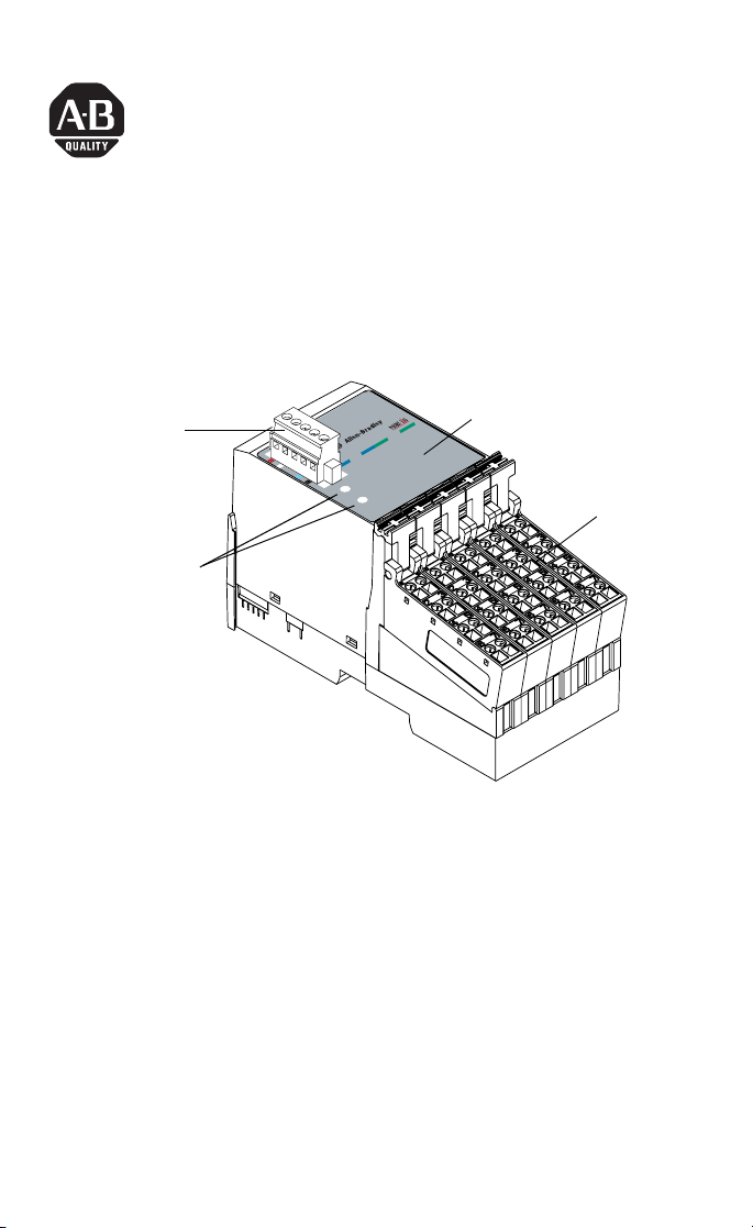
POINTBlock ac 8 Input/8 Relay Output Module
(Cat. No. 1734D-IA8XOW8, -IA8XOW8S)
I/O Status
DeviceNet
Connector
DeviceNet Node
Setting Switches
(1s and 10s)
Module
Status
Network
Status
Outputs
0
1
4
Inputs
5
0
6
1
2
9
-
3
0
3
-6
0
1
Indicators
4
5
6
7
2
3
7
Remote
Termination
Blocks
This 1734D input/output module is a DIN-rail mounted device with
an integrated DeviceNet communication interface, 8 ac inputs and 8
relay outputs, removable terminations, and a PointBus expansion port.
The expansion port allows you to add up to a maximum of 12
additional POINT I/O modules.
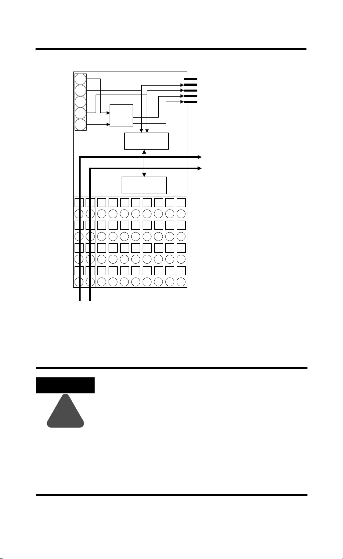
The module includes a non-isolated DeviceNet communication
interface. The 24V dc from the DeviceNet connection powers a
non-isolated dc/dc converter that generates +5V dc which powers the
POINTBlock electronics and connects to the PointBus port to power
the expansion I/O electronics.
The 1734-IA8XOW8 uses cage-clamp terminations, and the
1734-IA8XOW8S uses spring-clamp terminations.
POINTBlock is a trademark
of Rockwell Automation1 Publication 1734-5.23 - February 2000
Page 2
2 POINTBlock ac 8 Input/8 Relay Output Module
DeviceNet
Connector
Power
Connections
120V ac
24
CH
SH
CL
RT
24V
to 5V
Microprocessor
En
CH
PointBus Expansion Port
CL
5V
(allows expansion of up to
GND
12 POINT I/O modules)
Field Bus
Connector
I/O Circuits
I/O Connections
41971
ATTENTION
Whatever field power you supply is connected to
the internal field-power bus. For example, if
120V ac is applied to the power connections,
!
there will be 120V ac applied to the modules
through the internal field-power bus.
POINT I/O modules to the right of the module
will also have that internal power bus voltage
applied, unless you use a 1734-FPD to interrupt
and change the field power-bus voltage.
Publication 1734-5.23 - February 2000
Page 3
POINTBlock ac 8 Input/8 Relay Output Module 3
ATTENTION
POINTBlock is designed to be grounded through
the DIN rail to chassis ground. To assure proper
grounding of POINTBlock and POINT I/O
!
adapters and terminal bases to chassis ground, the
recommended DIN rail material is zinc-plated,
yellow-chromated steel. Mount POINTBlock,
POINT I/O adapters and terminal bases only to
zinc-plated, yellow-chromated steel.
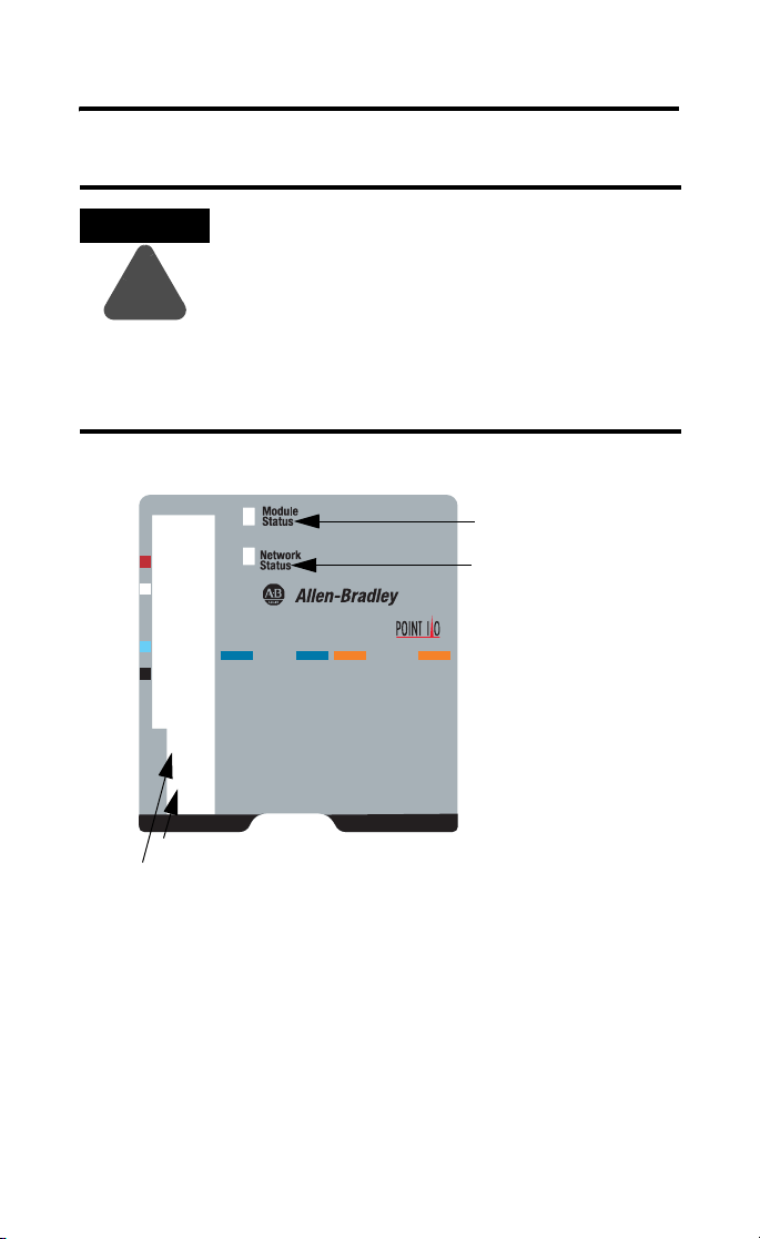
Inputs
0
1
10-60
0-9
1’s Node Address Rotary Switch
10’s Node Address Rotary Switch
2
3
Module Status
Network Status
4
5
6
7
Outputs
0
1
2
3
4
I/O status
5
6
7
42004
To set the node address, set the combination of 1’s and 10’s to
correspond to the required address. (For example, for 61, set the 10’s
switch to 6 and the 1’s switch to 1.)
Publication 1734-5.23 - February 2000
Page 4

4 POINTBlock ac 8 Input/8 Relay Output Module
Wiring
120V ac
Power
V ac
NC = No connection
L2/N = AC Return/Neutral L1 = AC Power
Field Power
01
NCNC0
NC
23
NC
45
L2in
L2in
67
L1in
L1in
RTB 0 RTB 1 RTB 2 RTB 3 RTB 4
Inputs Outputs
1
3
L2
L1
01
4
5
23
6
7
45
L2
L2
67
L1
L1
01
23
2
45
L2
67
L1
01
0A
23
45
2A
67
2B
This supply will be connected to the internal power bus.
0B
01
1A
23
1B
45
3A
67
3B
4A
6A
6B
4B
5A
5B
7A
7B
41976
Publication 1734-5.23 - February 2000
Page 5

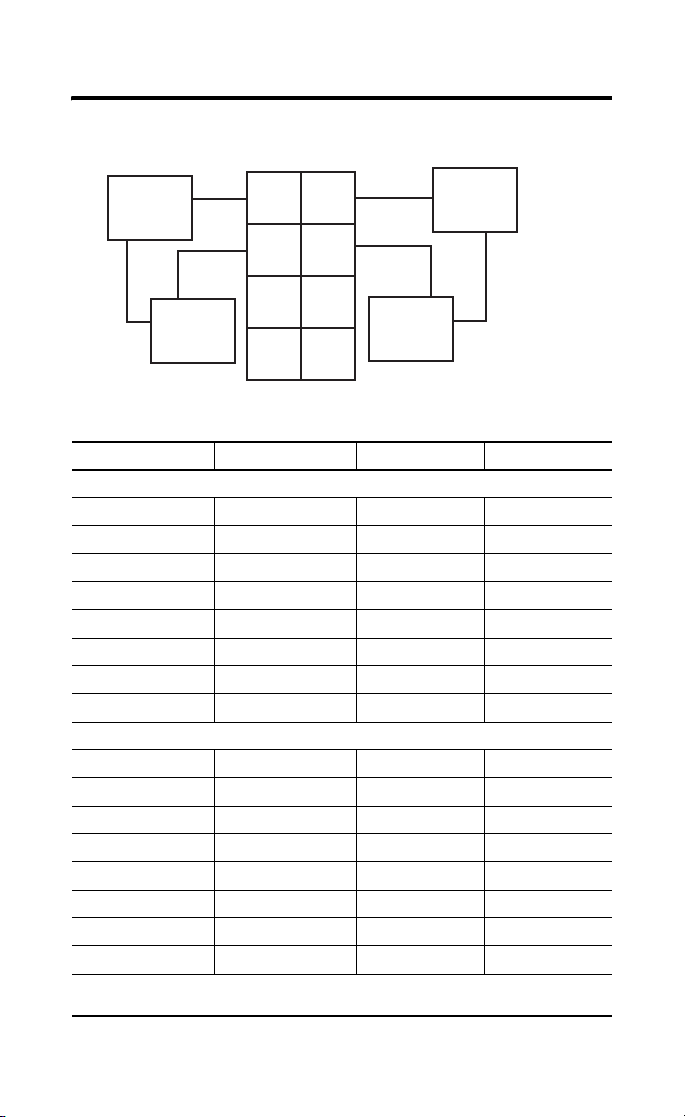
Input Wiring
POINTBlock ac 8 Input/8 Relay Output Module 5
In 1
In 3
L2
L1
1
3
5
7
41967ac
Prox
L1 = 120V ac
0
In 0
2
In 2
4
6
L2
L1
L2 = Return
Channel Input Terminal Return Voltage
Remote Termination Block 1
0 0 4 6
1 1 5 7
2 2 4 6
3 3 5 7
Remote Termination Block 2
4 0 4 6
5 1 5 7
6 2 4 6
7 3 5 7
120V ac is supplied through the internal power bus.
Prox
Note: When connecting more than 1 wire in a te rmination point, make sure
that both wires are the same gauge and type.
Publication 1734-5.23 - February 2000
Page 6
6 POINTBlock ac 8 Input/8 Relay Output Module
Output Wiring
Load powered by External Power
Power
Supply
Load
Out = Output channel relay contacts
L1 = 120V ac L2 = Return
0
Out 0A
2
Out 0B
4
Out 2A
6
Out 2B
1
Out 1A
3
Out 1B
5
Out 3A
7
Out 3B
Channel Output Common Supply
Remote Termination Block 3
0A 0
0B 2
1A 1
1B 3
2A 4
2B 6
3A 5
3B 7
Remote Termination Block 4
4A 0
4B 2
5A 1
5B 3
6A 4
6B 6
7A 5
7B 7
Supply voltage is 120V ac.
12/24V dc power for the module is provided by the internal power bus.
Power
Supply
Load
Publication 1734-5.23 - February 2000
Page 7

POINTBlock ac 8 Input/8 Relay Output Module 7
Note: When connecting more than 1 wire in a termination point,
make sure that both wires are the same gauge and type.
DeviceNet Connector Wiring
+V
CAN - High
Shield
CAN - Low
-V
42132
DeviceNet
connection
Red
White
Bare
Blue
Black
Publication 1734-5.23 - February 2000
Page 8

8 POINTBlock ac 8 Input/8 Relay Output Module
The following information applies
when operating this equipment in
hazardous locations:
Products marked “CL I, DIV 2, GP A, B, C, D” are
suitable for use in Class I Division 2 Groups A,
B, C, D, Hazardous Locations and nonhazardous
locations only. Each product is supplied with
markings on the rating nameplate indicating the
hazardous location temperature code. When
combining products within a system, the most
adverse temperature code (lowest “T” number)
may be used to help determine the overall
temperature code of the system. Combinations
of equipment in your system are subject to
investigation by the local Authority Having
Jurisdiction at the time of installation.
EXPLOSION HAZARD
WARNING
!
• Do not disconnect
equipment unless
power has been
removed or the area
is known to be
nonhazardous.
• Do not disconnect
connections to this
equipment unless
power has been
removed or the area
is known to be
nonhazardous.
Secure any external
connections that
mate to this
equipment by using
screws, sliding
latches, threaded
connectors, or other
means provided
with this product.
• Substitution of
components may
impair suitability for
Class I, Division 2.
• If this product
contains batteries,
they must only be
changed in an area
known to be
nonhazardous.
Informations sur l’utilisation de cet
équipement en environnements
dangereux :
Les produits marqués "CL I, DIV 2, GP A, B, C, D" ne
conviennent qu’à une utilisation en environnements
de Classe I Division 2 Groupes A, B, C, D dangereux
et non dangereux. Chaque produit est livré avec des
marquages sur sa plaque d’identification qui
indiquent le code de température pour les
environnements dangereux. Lorsque plusieurs
produits sont combinés dans un système, le code de
température le plus défavorable (code de
température le plus faible) peut être utilisé pour
déterminer le code de température global du
système. Les combinaisons d’équipements dans le
système sont sujettes à inspection par les autorités
locales qualifiées au moment de l’installation.
AVERTISSEMENT
!
RISQUE D’EXPLOSION
• Couper le courant ou
s’assurer que
l’environnement est
classé non dangereux
avant de débrancher
l'équipement.
• Couper le courant ou
s'assurer que
l’environnement est
classé non dangereux
avant de débrancher
les connecteurs. Fixer
tous les connecteurs
externes reliés à cet
équipement à l'aide
de vis, loquets
coulissants,
connecteurs filetés ou
autres moyens fournis
avec ce produit.
• La substitution de
composants peut
rendre cet
équipement inadapté
à une utilisation en
environnement de
Classe I, Division 2.
• S’assurer que
l’environnement est
classé non dangereux
avant de changer les
piles.
Publication 1734-5.23 - February 2000
Page 9

POINTBlock ac 8 Input/8 Relay Output Module 9
Specifications - 1734D-IA8XOW8, -IA8XOW8S
Input Specifications
ON-State Voltage 65V ac min
ON-State Current 5.0mA min
OFF-State Voltage 43V ac max
OFF-State Current 2.5mA max
Nominal Input Impedance 17.0kΩ
Input Delay Time
OFF to ON
ON to OFF
External AC Power Supply
20ms hardware + (0-65ms selectable)
20ms hardware + (0-65ms selectable)
120V ac, 60Hz nominal
Voltage
External AC Power Supply
85-132V ac, 47-63Hz
Voltage Range
Output Specifications
Relay Type Form A, normally open (N.O.)
Single Pole, Single Throw (SPST)
Output Voltage Range (load
dependent)
5-30V dc @ 2.0A resistive
48V dc @ 0.5A resistive
125V dc @ 0.25A resistive
125V ac @ 2.0A resistive
240V ac @ 2.0A resistive
Output Current Rating
(at rated power)
Resistive2A @ 5-30V dc
0.5A @ 48V dc
0.25A @ 125V dc
2A @ 125V ac
2A @ 240V ac
Inductive
2.0A steady state @ 5-30V dc, L/R - 7ms
0.5A steady state @ 48V dc, L/R = 7ms
0.25A steady state @ 125V dc, L/R = 7ms
2.0A steady state, 15A make @ 125V ac,
PF = cos θ = 0.4
2.0A steady state, 15A make @ 240V ac,
PF = cos θ = 0.4
Publication 1734-5.23 - February 2000
Page 10

10 POINTBlock ac 8 Input/8 Relay Output Module
Power Rating 250W max for 125V ac resistive loads
480W max for 240V ac resistive loads
60W max for 28.8V dc resistive loads
24W max for 48V dc resistive loads
31W max for 125V dc resistive loads
250VA max for 125V ac inductive loads
480VA max for 240V ac inductive loads
60VA max for 28.8V dc inductive loads
24VA max for 48V dc inductive loads
31VA max for 125V dc inductive loads
Minimum Load 10mA per point
Initial Contact Res. 30mΩ
Switching Frequency 1 operation/3s at rated load
Bounce Time 1.2ms average
Expected Contact Life 300K cycles resistive; 100K cycles inductive
Maximum OFF-State Leakage 1.5mA max
Output Delay Time 10ms max ON/OFF
General Specifications
Pointbus Output Current 1A max @ 5V ac output
DeviceNet Current 95mA maximum for POINTBlock
350mA for maximum with expansion of
12 POINT I/O modules
Number of POINT I/O
12 maximum added at expansion port
Expansion Modules
Isolation Voltage 1250Vrms or 2121V dc for 1s between user power
and DeviceNet
Indicators 1 red/ green module status indicator
1 red/green network status indicator
16 I/O status indicators (8 input/8 output)
Power Dissipation 2.0W maximum @ 24V dc
Power Consumption 8.2W maximum @ 24V dc
Field Power Bus
Supply Voltage
Voltage Range
Supply Current
Dimensions Inches
(Millimeters)
24V dc nominal
10-28.8V dc
10A max
3.00H x 2.36W x 5.25L
(76.2 Hx 60.0W x 133.4L)
Publication 1734-5.23 - February 2000
Page 11

POINTBlock ac 8 Input/8 Relay Output Module 11
Environmental Conditions
Operational Temperature
Storage Temperature
Relative Humidity
Shock Operating
Non-operating
Vibration
Conductors Wire Size
Category
-20 to +55oC (-4 to +131
-40 to 85oC (-40 to 185
o
F)
o
F)
5 to 95% noncondensing
30g peak acceleration, 11(±1)ms pulse width
50g peak acceleration, 11(±1)ms pulse width
Tested 5g @ 10-500Hz per IEC 68-2-6
14 AWG (2.5mm2) - 22 AWG (0.25mm2) solid or
stranded max
3/64 inch (1.2mm) insulation max
1
2
Terminal Base Screw Torque 5-7 pound-inches (0.5-0.6 Nm)
Field Wiring Terminations
DeviceNet
1 - Black Wire -V
2 - Blue Wire CAN Low
3 - Bare Wire Drain
4 - White Wire CAN High
5 - Red Wire +V
Field Power Supply 0 - No Connection1 - No Connection
2 - No Connection3 - No Connection
4 - AC return 5 - AC return
6 - AC power 7 - AC power
Mass 13.87 oz/393.41 grams
Agency Certification (when
product is marked)
• C-UL Listed
• C-UL Class I, Division 2 Groups A, B, C and D
certified
• UL listed
• CE marked for all applicable directives
• C-Tick marked for all applicable acts
1 Use this conductor category information for planning conductor routing. Refer to publication 1770-4.1,
“Industrial Automation Wiring and Grounding Guidelines for Noise Immunity.”
Publication 1734-5.23 - February 2000
Page 12

Publication 1734-5.23 - February 2000 PN 957236-90
© 2000 Rockwell International Corporation. Printed in USA
 Loading...