

Page 1
3G WiFi Router
Installation Guide
Model:
1
RP3G68
Page 2

Introduction
The 3G WiFi Router enables RISCO security systems to be
“self-contained” by enabling 3G communication as well as
providing WiFi connectivity for multiple wireless clients
(accessories), such as RISCO’s VUpoint IP cameras – without the
need for using a gateway/router at the premises.
Included Components
• 3G WiFi router (includes battery)
• Ethernet cable
• Power adapter with micro-USB to USB 2.0 cable
• Power socket adapters
• Mounting board
• Double-sided adhesive strips
Features and Benefits
• Compatible with RISCO security systems such as LightSYS2,
Agility3 and ProSYS Plus
• Supports multiple wireless or wired clients – RISCO’s indoor and
outdoor VUpoint IP cameras – for video verification of alarm events
• Small and compact
• Simple setup and configuration that can be performed off-site
• No software installation required
• Uses a standard SIM card
• Supports UPnP
Options for Utilization
The 3G WiFi router can be used in the system as follows:
• For use without any IP cameras or WiFi – for the purpose of
enabling 3G communication
• For utilizing wireless clients (wireless IP cameras) via WiFi
• For utilizing wired clients (wired IP cameras) via a LAN
2
Page 3
Warnings and Precautions
Only install and use this product in the manner for which it is
intended, and with regard to all applicable laws, regulations and
electrical code.
Do not use this product in locations where prohibited, or where
its use may hinder the operability and performance of sensitive
equipment (such as at medical and aviation facilities, and near heart
pacemakers and fire alarm systems), or where its use may result in
any other type of interference or risk.
Do not use where the risk of explosion exists from cellular device
usage, such as near flammable gasses or materials (for example, at
gas stations).
Do not install or use in extreme temperatures.
Do not get the router wet, nor handle it if wet.
Install the product out of reach of those for whom its use is
unintended, such as children.
Do not attempt to alter or repair the product yourself – always
contact your supplier for service issues.
Do not place near any vulnerable or sensitive storage media
(such as magnetic storage media) for which data-loss may result.
For batteries, never use recharging devices not approved by the
manufacturer, as it may result in explosion, damage, injury or death.
Always dispose of batteries in compliance with applicable law. Only
use the correct battery type, as specified.
Use this product within the specified ranges for operating and
storage environments (see Product Specification, page 15).
3
Page 4
Initial Setup and Configuration Steps
Step 1: Installing the SIM Card
A SIM card is required to establish GPRS communication.
1. Open the router cover and then insert the SIM card into its holder.
NOTE: If using IP cameras, a SIM package with a public IP is
required, with at least 3 GB per month recommended.
Otherwise, for Cloud-based 3G GPRS communication (without
using IP cameras), a public IP is not needed. Most mobile
providers offer a public IP only together with a fixed IP.
2. Remove tape from the battery terminals, install the battery in the
router, and then close up the router cover.
3. If utilizing the router only for GPRS (without WiFi or IP cameras),
go to Installing the Router-Mounting Board Assembly, page 7.
Step 2: Connecting the Router to a Laptop
Prior to installation, first connect the router to a laptop or PC, where
you view the configuration screens and define relevant settings.
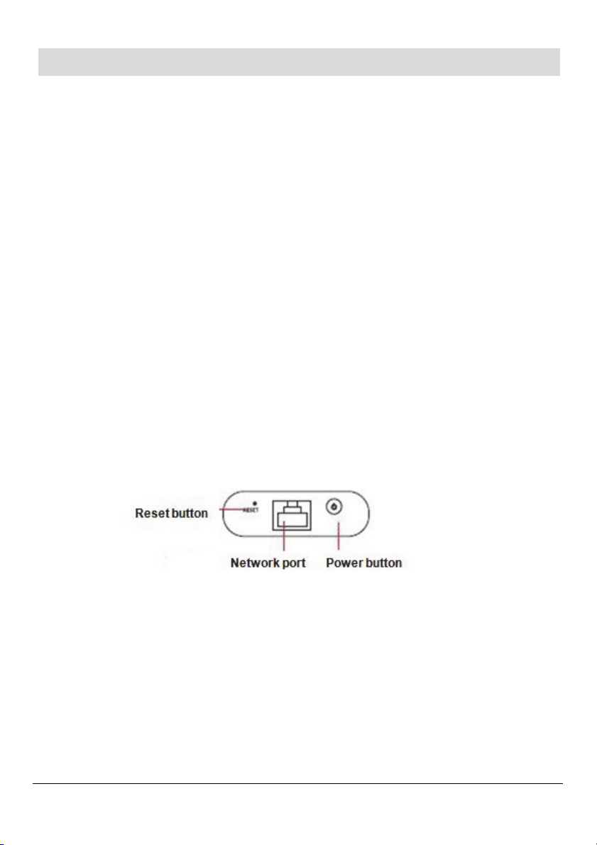
1. Using the Ethernet cable, connect the network port on the router
to the network port on the laptop.
2. Connect the power cord to the micro-USB port on the router, and
then plug the other end (power adapter) into an electrical socket.
3. Press the router’s Power button for about 5 seconds. Ignore the
Power Status LED color (indicates battery level), but wait a few
seconds for the router to initialize and the other LEDs (Signal,
Network, and WiFi) to stabilize. See LED Indicators, page 15.
4
Page 5

Step 3: Defining Router Settings
Define router settings from the screens that display. First configure
the Internet connection. If the system has IP cameras (in either a
wireless or wired configuration), you’ll need to verify the UPnP
settings. For IP cameras in a wireless configuration, you’ll also need
to configure the WiFi connection and encryption.
NOTE: Standard settings are provided here. Some settings and
defaults may differ, according to the ISP.
Defining the Internet Connection
1. In a Web browser type: http://192.168.8.1.
2. At the login, type Admin for both user name and password.
3. Click the Mode menu, select 3G Wireless Router Mode, and then
click Apply.
4. Click the 3G menu. From Setup (default screen), in the 3G ISP
field clear the Auto select 3G ISP checkbox and then select the
provider from the dropdown list.
5. In the APN field, enter the provider-supplied APN.
NOTE: If the system has IP cameras, enter the provider-supplied
APN per public IP.
NOTE: Depending on the provider, you may or may not need to
enter a PIN or user name and password. For some providers,
these fields may populate automatically.
6. Click Apply.
7. From the 3G menu, click Break-Detection, and then from the
Break Detection dropdown list, select Enable.
8. At the Object dropdown list, select Sent ICMP to the Gateway,
and then select the Gateway checkbox.
9. Click Apply.
5
Page 6

Verifying UPnP Settings (for Wired and Wireless IP Cameras)
1. Click the Admin menu, click Management, and then make sure
the Enable UPnP checkbox is selected.
2. If your system doesn’t have WiFi clients (wireless IP cameras),
skip the next section, power-off the router and disconnect its
cables, and go to Installing the Router-Mounting Board Assembly,
page 7.
Defining WiFi Connection & Encryption (for Wireless IP
Cameras)
1. Click the Wireless menu, click Basic, and then make sure the
Wireless Enabled checkbox is selected.
2. In the SSID field, enter a name for your wireless network.
3. Although selecting Do Not Broadcast SSID enhances security, do
not select it yet as you will need to view the WiFi network for
configuration later on in this manual.
4. Click the Wireless menu, and then click Security. From the
Security Mode dropdown list, select WPA-PSK/WPA2-PSK.
5. In the WPA-PSK key field, enter a unique 8-character password,
and then click Apply.
6. Click the Status menu, and then click Summary; here you can
view all the configuration settings, check if you are connected to
the Internet, view the IP address, and see if the signal strength is
adequate (90% or greater).
7. On the Summary screen, click the Disconnect button, and then
click the Connect button for the settings to take effect; the
displayed information will also be updated.
8. Power-off the router by pressing the Power button for about 5
seconds, and then disconnect the power and network cables.
6
Page 7

Installing the Router-Mounting Board Assembly
The mounting board holds the router inside the Plastic Enclosure or
Plastic Accessory Box. The router is fastened onto the mounting
board with the provided ultra-strong adhesive strips.
NOTE: The router should not be installed inside a metal enclosure.
IMPORTANT: Due to clearance limitations for the cables in the
Plastic Enclosure and Plastic Accessory Box, it is recommended to
install the router as follows:
1. First attach the power cable and Ethernet cable to the router.
2. Then install only the mounting board onto the enclosure/box. For
the Plastic Enclosure, install onto the 2 standoffs (see page 8), and
for the Plastic Accessory Box, install using the provided screws
(see page 9).
3. Place the adhesive strip on the back side of the router.
4. Carefully position the router onto the mounting board, making
sure the power adapter and Ethernet cables both have enough
room for clearance and routing, and so the enclosure/box cover
can be closed – for the Plastic Enclosure, see the guidelines on
page 8, and for the Plastic Accessory Box, see the guidelines
on page 9.
NOTE: The adhesive strip has a very strong bond and is not meant
to be removed.
NOTE: For additional details on installing the Plastic Enclosure and
Plastic Accessory Box, refer to their respective instructions.
7
Page 8

Installing in the LightSYS Plastic Enclosure
The Plastic Enclosure is used for LightSYS. The side of the router
with the micro-USB port (for the power adapter cable) should be
affixed to extend about 6 mm from the right edge of the mounting
board, and should be flush with (and about 2 mm above) the lower
edge of the mounting board:
Ethernet cable Power adapter cable (micro-USB)
Standoffs
Ethernet cable to port on IP module
8
Page 9

Installing in the Plastic Accessory Box
The RP128B50000A “B5” Plastic Accessory Box can be used with
Agility, or with other RISCO systems – and is necessary for systems
that have the main panel in a metal enclosure.
The side of the router with the micro-USB port (for the power
adapter cable) should be affixed within 15 mm—18 mm from the
upper edge of the mounting board:
Power adapter cable (micro-USB)
Ethernet cable
NOTE: The router can be installed at one of the two locations (left
or right side) that are used for installing the 8-zone expander.
9
Page 10

Modes of Operation
3G Communication Only (without IP Cameras or WiFi)
After the router-mounting board assembly has been installed, do the
following:
1. Use an Ethernet cable to connect the router to the IP module.
2. Connect the power adapter cord to the router’s micro-USB port,
with the other end of the cord routed through the opening on the
back of the main panel/Plastic Accessory Box (together with the
Ethernet cable if applicable).
3. Close up the main panel/ Plastic Accessory Box, connect the other
end of the cord to the power adapter, and plug the power adapter
into an electrical socket; a blue Network Status LED on the router
indicates successful 3G network connectivity (see LED Indicators,
page 15).
Options for use with IP Cameras
IP cameras can be used in the system as follows:
• Using IP cameras in a wireless (WiFi) network configuration:
The router connects to the IP module on the main panel, and the
IP cameras are connected via WiFi.
• Using IP cameras in a wired (LAN) configuration: Any standard
10/100 multi-port Ethernet switch is needed (for example, an
8-port switch) which connects to each IP camera, the IP module,
and the router.
10
Page 11

Setup Prior to IP Camera & WiFi Configuration
Regardless whether wired or wireless-enabled IP cameras are used
(via a LAN or WiFi), prior to adding and configuring the IP cameras
and establishing a WiFi connection (if applicable), you first need to
set up the components for these tasks. Use any standard, multi-port
10/100 switch and Ethernet cables to connect the system as follows:
NOTE: The 10/100 switch is not provided. A single 60 cm Ethernet
cable is provided.
To set up the system before configuring IP cameras and WiFi:
1. Use Ethernet cables to connect the 10/100 switch to the following:
• Network port on the 3G router
• Network port on the laptop / PC
• Network port on the main panel’s IP module
• Network port on each IP camera
2. Power up the connected devices and wait a few minutes. A RED
network indicator light indicates an IP camera is ready for
configuring from the RISCO Installer Administrative Application
(see page 12).
11
Page 12

RISCO Installer Administrative Application
Via the RISCO Cloud, the Installer Administrative Application
enables you to add IP cameras to the network (LAN or WiFi) and
configure the camera settings. It also enables you to establish a WiFi
connection.
Adding IP Cameras
To add and configure IP cameras via the Cloud:
1. Log into the RISCO Installer Administration application at
www.riscocloud.com/ELAS/WAApp and enter your user name
and password (click Sign Up as Installer Admin if you need to
create new login credentials).
NOTE: It is recommended to use Google Chrome or Mozilla
Firefox to log into the Installer Administration application.
NOTE: Refer to the RISCO Cloud Installer Application manual
for more details.
2. Select the Control Panels List link. The Control Panels List page is
displayed.
3. From the Control Panels List page, select the Control Panel you
wish to view. The Control Panels Update page is displayed.
4. Click the Network Cameras link in the left-hand column; the IP
Cameras List page is displayed.
5. Click Add Camera; the Add Camera dialog box is displayed.
12
Page 13

6. Define the following fields in the Add Camera dialog box:
Field Description
Label Enter a name for the camera
Partitions Select the partition(s) from the list of defined partitions
Type Choose the RISCO camera type
Enter the MAC address into this field. The MAC
address (media access control address) is the unique
MAC
Address
identifier assigned to the IP camera for
communications on the physical network.
NOTE: The MAC address is case sensitive and should
be entered exactly as it is shown on the box or on the
back cover of the IP camera, e.g. AA:BB:CC:DD:EE:FF
7. Click Add.
If the “Camera was identified successfully” message is displayed, go
straight to Establishing a WiFi Connection, page 13.
If an “unable to configure Internet Access”, “UPnP Client Error” or
similar message is displayed, refer to the Troubleshooting section in
the IP Camera Installation documentation.
NOTE: This message is only relevant for IP cameras that are
physically connected to the LAN network via the router.
Establishing a WiFi Connection
To establish a WiFi connection:
1. Select Connect to WiFi to establish a wireless network connection;
a list of available wireless networks is displayed.
2. Select your wireless network from the list and click Connect.
NOTE: If your network is password protected, the password
must be entered into the displayed password screen.
13
Page 14

3. Click OK to establish the wireless connection
IMPORTANT: Once a wireless connection has been
established, don’t forget to disconnect the Ethernet cables that
connect the wireless IP cameras to the router, and to install the
wireless IP cameras at the premises.
4. Once the “camera is ready for use” message is displayed, click OK.
The defined IP camera is displayed in the IP Cameras page.
NOTE: You can edit or delete the selected IP camera.
NOTE: For more information, such as defining IP camera triggers
and troubleshooting, see the IP camera installation documentation.
5. In the Web browser enter http://192.168.8.1 to re-open the router
configuration screen, and at the login screen enter Admin for both
user name and password.
6. For enhanced security, from the Wireless menu (Basic tab) you can
select the Do not broadcast SSID checkbox, and then click Apply.
7. Disconnect the Ethernet switch from the powered-down laptop,
router, and IP module.
Connecting the Router for Operation
Having finished with the IP camera and WiFi configuration, you can
now connect the router to the IP module via Ethernet cable, and
power-up your system components for operation.
14
Page 15

LED Indicators
LED Indicator Status Description
Red ON No signal or SIM card, incorrect SIM card
Pink ON Weak signal
Signal
intensity
Network
status
WiFi status
Power status
Blue ON Good signal
OFF Shut off
Green flashing Connecting to WAN
Green ON WAN is connected
Blue flashing Connecting to 3G network
Blue ON 3G network is connected
OFF Shut off
Blue flashing Connecting to WiFi
Blue ON WiFi is connected
OFF Shut off
Green Charging
Green turned OFF Charging has completed
Blue Battery level is high
Pink Battery level is middle
Red Battery level is low, needs charging
OFF Router is shut off
Product Specification
HARDWARE / GENERAL
Physical interfaces Network port (1) / Micro USB (1) / USB 2.0 port (1)
• Windows, Mac
Computer requirements
Power
Backup battery 3.7V, 3000 mAh, Lithium
Dimensions (L/W/H) 94 x 50 x 20 (mm) / 3.7 x 1.97 x 0.79 (in)
Weight (with battery) 120 g (4.2 oz)
Operating Temperature 0° C—50° C (32° F—122° F)
Storage temperature -10° C—70° C (14° F—158° F)
15
• USB 2.0
• Web browser: Explorer, Safari, Firefox, Chrome
Input: 100—240 VAC; 50/60 Hz
Output: 5 VDC, 1A
Page 16

Operating humidity 10%—90%
Storage humidity 5%—95%
Login IP Address: 192.168.8.1
Login user name: admin / Login password: admin
Factory default settings
Supported storage formats Micro SD slot, USB storage device (via USB port)
Certification CE
WIRELESS / NETWORK
WLAN standards IEEE 802.11b/g/n
Wireless speed Up to 150 Mbps
Transmission rate
Frequency
Power class
Band 2.412 GHz—2.484 GHz
SIM/USIM card
Router settings SSID, Gateway, DHCP, MAC, APN
Basic features
Security WPA-PSK, WPA2-PSK, and WPA&WPA2-PSK
UPnP Default is ON
SSID:WIFI-****** (****** represents the last six
characters in device's MAC address)
WIFI password: 12345678
EVDO Rev. B: up to 14.7 Mbps DL / 5.4 Mbps UL
EVDO Rev. A: up to 3.1 Mbps DL / 1.8 Mbps UL,
HSPA + up to 14.4 Mbps DL, HSDPA up to 7.2
Mbps DL, HSUPA up to 5.76 Mbps UL
EDGE class 12, up to 236.8 Kbps
CDMA 2000 : 800
UMTS: 2100 / 1900 / 850
GSM/ GPRS/EDGE: 850/900/1800/1900
WCDMA = Power Class 3
GPRS/GSM 900 = Power Class 4
GPRS/GSM 1800 = Power Class 1
EDGE 900 = Power Class E2
EDGE 1800 = Power Class E2(+26dBm)
Standard 6 PIN SIM card interface,
compliant with 3GPP 31.101 and 31.102
Network Mode/Channel/Channel Width:
Changeable
SSID: Configurable, Broadcast: Enable/Disable
(
+24dBm)
(
(
+27dBm)
+33dBm)
(
+30dBm)
Copyright 2014, RISCO Group. All rights reserved.
12/2014
16
5IN2396
 Loading...