

Page 1

Model Da-P1
Machine Code:
M187
Field Service Manual
January, 2015
Page 2

Page 3

Important Safety Notices
Important Safety Notices
Prevention of Physical Injury
1. Before disassembling or assembling parts of the main machine and peripherals, make sure that the
power cord of the main machine is unplugged.
2. The wall outlet should be near the machine and easily accessible.
3. Note that some components of the machine and the paper tray unit are supplied with electrical
voltage even if the main power switch is turned off.
4. If any adjustment or operation check has to be made with exterior covers off or open while the
main switch is turned on, keep hands away from electrified or mechanically driven components.
5. The inside and the metal parts of the fusing unit become extremely hot while the machine is
operating. Be careful to avoid touching those components with your bare hands.
• To prevent a fire or explosion, keep the machine away from flammable liquids, gases, and
aerosols.
Health Safety Conditions
1. Toner and developer is non-toxic, but if you get either of them in your eyes by accident, it may
cause temporary eye discomfort. Immediately wash eyes with plenty of water. If unsuccessful, get
medical attention.
2. This machine, which uses a high voltage power source, can generate ozone gas. High ozone
density is harmful to human health. Therefore, the machine must be installed in a well-ventilated
room.
Observance of Electrical Safety Standards
1. This machine and its peripherals must be serviced by a customer service representative who has
completed the training course on those models.
2. The NVRAM on the system control board has a lithium battery which can explode if replaced
incorrectly. Replace the NVRAM only with an identical one. The manufacturer recommends
replacing the entire NVRAM. Do not recharge or burn this battery. Used NVRAM must be handled
in accordance with local regulations.
1
Page 4

Handling Toner
• Work carefully when removing paper jams or replacing toner bottles or cartridges to avoid spilling
toner on clothing or the hands.
• If toner is inhaled, immediately gargle with large amounts of cold water and move to a well
ventilated location. If there are signs of irritation or other problems, seek medical attention.
• If toner gets on the skin, wash immediately with soap and cold running water.
• If toner gets into the eyes, flush the eyes with cold running water or eye wash. If there are signs of
irritation or other problems, seek medical attention.
• If toner is swallowed, drink a large amount of cold water to dilute the ingested toner. If there are
signs of any problem, seek medical attention.
• If toner spills on clothing, wash the affected area immediately with soap and cold water. Never use
hot water! Hot water can cause toner to set and permanently stain fabric.
• Always store toner and developer supplies such as toner and developer packages, cartridges, and
bottles (including used toner and empty bottles and cartridges) out of the reach of children.
• Always store fresh toner supplies or empty bottles or cartridges in a cool, dry location that is not
exposed to direct sunlight.
• Do not use a vacuum cleaner to remove spilled toner (including used toner). Vacuumed toner may
cause a fire or explosion due to sparks or electrical contact inside the cleaner. However, it is
possible to use a cleaner designed to be dust explosion-proof. If toner is spilled over the floor,
sweep up spilled toner slowly and clean up any remaining toner with a wet cloth.
Safety and Ecological Notes for Disposal
1. Do not incinerate toner bottles or used toner. Toner dust may ignite suddenly when exposed to an
open flame.
2. Dispose of used toner, the maintenance unit which includes developer or the organic
photoconductor in accordance with local regulations. (These are non-toxic supplies.)
3. Dispose of replaced parts in accordance with local regulations.
4. When keeping used lithium batteries in order to dispose of them later, do not put more than 100
batteries per sealed box. Storing larger numbers or not sealing them apart may lead to chemical
reactions and heat build-up.
2
Page 5
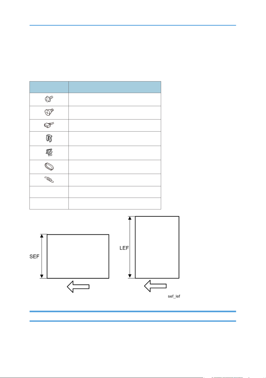
Symbols, Abbreviations and Trademarks
This manual uses several symbols and abbreviations. The meaning of those symbols and abbreviations
are as follows:
Symbol What is means
Screw
Shoulder screw
Connector
Clip ring
Clamp
Timing belt
Spring
SEF Short Edge Feed
LEF Long Edge Feed
Trademarks
Adobe, Acrobat, PostScript, PostScript 3, and Reader are either registered trademarks or trademarks of
Adobe Systems Incorporated in the United States and/or other countries.
3
Page 6

Mac OS, OS X, and Safari are trademarks of Apple Inc., registered in the United States and other
countries.
Firefox® is a registered trademark of the Mozilla Foundation.
Java is a registered trademark of Oracle and/or its affiliates.
JAWS® is a registered trademark of Freedom Scientific, Inc., St. Petersburg, Florida and/or other
countries.
Microsoft®, Windows®, Windows Server®, Windows Vista®, and Internet Explorer® are either
registered trademarks or trademarks of Microsoft Corporation in the United States and/or other
countries.
Monotype is a registered trademark of Monotype Imaging Inc.
NetWare, IPX, IPX/SPX, NCP, and NDS are either registered trademarks or trademarks of Novell, Inc.
PCL® is a registered trademark of Hewlett-Packard Company.
The proper name of Internet Explorer 6 is Microsoft® Internet Explorer® 6.
The proper name of Internet Explorer 8 is Windows® Internet Explorer® 8.
The proper names of the Windows operating systems are as follows:
• The product names of Windows XP are as follows:
Microsoft® Windows® XP Professional Edition
Microsoft® Windows® XP Home Edition
Microsoft® Windows® XP Media Center Edition
Microsoft® Windows® XP Tablet PC Edition
• The product names of Windows Vista are as follows:
Microsoft® Windows Vista® Ultimate
Microsoft® Windows Vista® Business
Microsoft® Windows Vista® Home Premium
Microsoft® Windows Vista® Home Basic
Microsoft® Windows Vista® Enterprise
• The product names of Windows 7 are as follows:
Microsoft® Windows® 7 Home Premium
Microsoft® Windows® 7 Professional
Microsoft® Windows® 7 Ultimate
Microsoft® Windows® 7 Enterprise
• The product names of Windows 8 are as follows:
Microsoft® Windows® 8
Microsoft® Windows® 8 Pro
4
Page 7

Microsoft® Windows® 8 Enterprise
• The product names of Windows 8.1 are as follows:
Microsoft® Windows® 8.1
Microsoft® Windows® 8.1 Pro
Microsoft® Windows® 8.1 Enterprise
• The product names of Windows Server 2003 are as follows:
Microsoft® Windows Server® 2003 Standard Edition
Microsoft® Windows Server® 2003 Enterprise Edition
• The product names of Windows Server 2003 R2 are as follows:
Microsoft® Windows Server® 2003 R2 Standard Edition
Microsoft® Windows Server® 2003 R2 Enterprise Edition
• The product names of Windows Server 2008 are as follows:
Microsoft® Windows Server® 2008 Standard
Microsoft® Windows Server® 2008 Enterprise
• The product names of Windows Server 2008 R2 are as follows:
Microsoft® Windows Server® 2008 R2 Standard
Microsoft® Windows Server® 2008 R2 Enterprise
• The product names of Windows Server 2012 are as follows:
Microsoft® Windows Server® 2012 Foundation
Microsoft® Windows Server® 2012 Essentials
Microsoft® Windows Server® 2012 Standard
• The product names of Windows Server 2012 R2 are as follows:
Microsoft® Windows Server® 2012 R2 Foundation
Microsoft® Windows Server® 2012 R2 Essentials
Microsoft® Windows Server® 2012 R2 Standard
Other product names used herein are for identification purposes only and might be trademarks of their
respective companies. We disclaim any and all rights to those marks.
Microsoft product screen shots reprinted with permission from Microsoft Corporation.
5
Page 8

TABLE OF CONTENTS
Important Safety Notices................................................................................................................................... 1
Important Safety Notices............................................................................................................................... 1
Prevention of Physical Injury................................................................................................................. 1
Health Safety Conditions...................................................................................................................... 1
Observance of Electrical Safety Standards.........................................................................................1
Handling Toner...................................................................................................................................... 2
Safety and Ecological Notes for Disposal................................................................................................... 2
Symbols, Abbreviations and Trademarks.........................................................................................................3
Trademarks..................................................................................................................................................... 3
1. Product Information
Product Overview.............................................................................................................................................15
Component Layout.......................................................................................................................................15
Paper Path.................................................................................................................................................... 16
Drive Layout..................................................................................................................................................17
Machine Codes and Peripheral Configuration............................................................................................. 18
Machine Codes and Peripheral Configuration......................................................................................... 18
Specifications....................................................................................................................................................21
2. Installation
Installation Requirements................................................................................................................................. 23
Environment..................................................................................................................................................23
Machine Space Requirements....................................................................................................................24
Machine Dimensions................................................................................................................................... 24
Power Requirements.................................................................................................................................... 25
Main Machine Installation...............................................................................................................................26
Accessory Check..........................................................................................................................................26
Instructions for the Customers......................................................................................................................26
Moving the Machine................................................................................................................................... 26
Security Settings........................................................................................................................................... 28
Changing an Administrator's Password.............................................................................................28
Configuring SSL/TLS...........................................................................................................................28
Paper Feed Unit TK2010................................................................................................................................ 29
Component Check.......................................................................................................................................29
Installation Procedure..................................................................................................................................29
6
Page 9

USB Device Server Option Type M12...........................................................................................................31
Component Check.......................................................................................................................................31
Interface Board Surface......................................................................................................................31
Installation Procedure..................................................................................................................................32
What Do the LED Indications Mean?................................................................................................ 35
Notes for Energy Save Mode Setting................................................................................................36
IP Address Setting........................................................................................................................................ 36
SD Card Appli Move.......................................................................................................................................39
Overview...................................................................................................................................................... 39
Notes on Using the SD Merge Function.................................................................................................... 39
SD Card Applications..................................................................................................................................40
Move Exec................................................................................................................................................... 40
Undo Exec.................................................................................................................................................... 42
Settings for @Remote Service..........................................................................................................................44
Check points before making @Remote settings.........................................................................................44
Execute the @Remote Settings.................................................................................................................... 44
3. Preventive Maintenance
Preventive Maintenance Tables...................................................................................................................... 49
Preventive Maintenance Tables..................................................................................................................49
Image Quality Standards................................................................................................................................ 50
Image Quality Standards............................................................................................................................50
Paper Transfer Quality Standards.................................................................................................................. 51
Paper Transfer Quality Standards.............................................................................................................. 51
4. Replacement and Adjustment
General Cautions.............................................................................................................................................53
Notes on the Main Power Switch...............................................................................................................53
Characteristics of the Push Switch (DC Switch).................................................................................53
Shutdown Method...............................................................................................................................54
Forced Shutdown................................................................................................................................ 55
Special Tools ................................................................................................................................................... 56
Exterior Covers................................................................................................................................................. 57
Front Cover...................................................................................................................................................57
Left Cover......................................................................................................................................................58
7
Page 10

Right Cover...................................................................................................................................................60
Rear Cover, Rear Lower Cover...................................................................................................................63
By-pass Tray.................................................................................................................................................66
Upper Cover................................................................................................................................................ 67
Operation Panel...........................................................................................................................................68
LED Optics........................................................................................................................................................ 72
LED Unit........................................................................................................................................................ 72
PCDU.................................................................................................................................................................78
PCDU............................................................................................................................................................ 78
Toner Cartridge................................................................................................................................................ 79
Toner Cartridge............................................................................................................................................79
Image Transfer..................................................................................................................................................81
Image Transfer Roller...................................................................................................................................81
Drive Unit.......................................................................................................................................................... 83
Main Motor..................................................................................................................................................83
Exit/Reverse Motor..................................................................................................................................... 84
Registration Clutch....................................................................................................................................... 86
Paper Feed Clutch........................................................................................................................................86
By-pass Feed Clutch.................................................................................................................................... 87
By-pass Bottom Plate Clutch........................................................................................................................89
Drive Unit......................................................................................................................................................89
Gear Unit......................................................................................................................................................89
Toner Supply Clutch.................................................................................................................................... 92
Relay Clutch................................................................................................................................................. 93
Duplex Clutch...............................................................................................................................................94
Junction Gate Solenoid............................................................................................................................... 95
Fusing................................................................................................................................................................ 96
Fusing Unit.................................................................................................................................................... 96
Upper Fusing Unit, Lower Fusing Unit........................................................................................................ 98
Fusing Pressure Roller.................................................................................................................................. 99
Fusing Lamp, Hot Roller............................................................................................................................ 100
Thermostat..................................................................................................................................................104
Thermistor...................................................................................................................................................104
8
Page 11

Hot Roller Stripper.....................................................................................................................................106
Paper Feed..................................................................................................................................................... 107
Paper Feed Tray........................................................................................................................................ 107
Paper Feed Roller......................................................................................................................................107
Friction Roller, Torque Limiter................................................................................................................... 108
Paper End Sensor...................................................................................................................................... 109
By-pass Feed Unit......................................................................................................................................110
By-pass Feed Roller...................................................................................................................................112
By-pass Friction Pad..................................................................................................................................114
By-pass Paper End Sensor........................................................................................................................115
By-pass Bottom Plate HP Sensor.............................................................................................................. 116
Paper Size Detection Switch.....................................................................................................................117
Paper Transport..............................................................................................................................................119
Paper Exit Unit........................................................................................................................................... 119
Paper Exit Sensor.......................................................................................................................................121
Paper Overflow Sensor.............................................................................................................................121
Duplex Reverse Sensor............................................................................................................................. 121
Duplex Entrance Sensor............................................................................................................................123
Registration Roller (Driven).......................................................................................................................123
Registration Roller (Drive)......................................................................................................................... 126
Registration Sensor....................................................................................................................................128
Electrical Components...................................................................................................................................130
Controller Box............................................................................................................................................130
PSU............................................................................................................................................................. 131
Controller Board........................................................................................................................................134
Before replacing the controller board in the model without HDD................................................134
Replacement Procedure................................................................................................................... 134
After installing the controller board.................................................................................................136
NVRAM on the Controller Board.............................................................................................................136
BCU............................................................................................................................................................ 137
EEPROM on the BCU................................................................................................................................138
Toner End Sensor...................................................................................................................................... 139
HVPS...........................................................................................................................................................140
9
Page 12

HVPS with Bracket.....................................................................................................................................140
PCDU Cooling Fan....................................................................................................................................141
PCDU Cooling Fan with Duct................................................................................................................... 141
PSU Cooling Fan....................................................................................................................................... 142
DC Switch.................................................................................................................................................. 142
Front Cover Interlock Switch.....................................................................................................................143
Front Cover Interlock Switch with Bracket...............................................................................................144
Rear Cover Interlock Switch..................................................................................................................... 144
DIMM.........................................................................................................................................................145
Temp Humid Sensor.................................................................................................................................. 147
Envelope Lever Detection Switch............................................................................................................. 147
5. System Maintenance
Service Program Mode.................................................................................................................................149
SP Tables....................................................................................................................................................149
Enabling and Disabling Service Program Mode....................................................................................149
Entering SP Mode.............................................................................................................................149
Exiting SP Mode............................................................................................................................... 149
Types of SP Modes....................................................................................................................................150
Service Mode Lock/Unlock..................................................................................................................... 150
Updating the Firmware..................................................................................................................................151
Overview....................................................................................................................................................151
Type of Firmware.......................................................................................................................................151
Updating Firmware................................................................................................................................... 152
Before You Begin..............................................................................................................................152
Preparation........................................................................................................................................153
Updating Procedure......................................................................................................................... 153
Firmware Update Error.....................................................................................................................156
Recovery after Power Loss............................................................................................................... 156
Handling Firmware Update Errors...........................................................................................................157
Uploading/Downloading NVRAM Data....................................................................................................162
Uploading Content of NVRAM to an SD Card...................................................................................... 162
Downloading an SD Card to NVRAM....................................................................................................163
Capturing Log to SD card............................................................................................................................. 164
10
Page 13

Overview....................................................................................................................................................164
Security of the Operation Log..........................................................................................................165
Retrieving the Debug Logs........................................................................................................................ 165
Procedure for Retrieving the Debug Log.........................................................................................166
Address Book Upload/Download.............................................................................................................. 167
Information List...........................................................................................................................................167
Upload (Backup) to SD Card...................................................................................................................167
Download (Restore) to Machine..............................................................................................................168
Erasing the Backup Data.......................................................................................................................... 168
6. Troubleshooting
Self-Diagnostic Mode................................................................................................................................... 169
Self-Diagnostic Mode at Power On.........................................................................................................169
Service Call.................................................................................................................................................... 170
Summary.................................................................................................................................................... 170
When a Level “D” SC code occurs.................................................................................................170
SC100........................................................................................................................................................171
SC200 (LED Optics)................................................................................................................................. 171
SC300 (Image Processing – 1)............................................................................................................... 173
SC400 (Image Processing – 2)............................................................................................................... 175
SC500 (Paper Feed and Fusing)............................................................................................................. 176
SC600 (Device Communication).............................................................................................................185
SC700 (Peripherals)................................................................................................................................. 196
SC800 (Controller)................................................................................................................................... 197
SC900 (Others).........................................................................................................................................262
Jam Detection.................................................................................................................................................269
Jam Displays.............................................................................................................................................. 269
Jam History.................................................................................................................................................269
Sensor Position Layout.............................................................................................................................. 270
Sensor Position...........................................................................................................................................270
Main Machine.................................................................................................................................. 271
Optional Bank...................................................................................................................................272
Troubleshooting............................................................................................................................................. 273
Test Pattern Printing....................................................................................................................................273
11
Page 14

Image Position Adjustment........................................................................................................................274
Registration Adjustment.............................................................................................................................274
Print Area...........................................................................................................................................274
Adjustment Reference Values...........................................................................................................275
Adjustment Procedure.......................................................................................................................275
Image Problem.......................................................................................................................................... 275
Problem at Regular Intervals............................................................................................................275
When Vertical Banding is Generated.............................................................................................277
When Black Spots are Generated on Print Image.........................................................................277
When Toner Smears Appear on the Backside of the Printouts..................................................... 278
Paper Feed (Skew)....................................................................................................................................279
Recycled or Thin Paper Is Severely Curled after Printing.......................................................................279
Electrical Component Defects.......................................................................................................................280
Electrical Components.............................................................................................................................. 280
Fuses........................................................................................................................................................... 281
BCU....................................................................................................................................................281
PSU.................................................................................................................................................... 283
7. Energy Save
Energy Save................................................................................................................................................... 285
Energy Saver Modes................................................................................................................................ 285
Sleep Mode Setting..........................................................................................................................285
Weekly Timer.................................................................................................................................... 286
Eco Night Mode............................................................................................................................... 286
Fusing Off Mode...............................................................................................................................289
Fusing Heater Off on Stndby........................................................................................................... 290
Return to Stand-by Mode.................................................................................................................290
Recommendation..............................................................................................................................290
Energy Save Effectiveness........................................................................................................................ 291
Paper Save.....................................................................................................................................................293
Effectiveness of Duplex/Combine Function............................................................................................ 293
1. Duplex:..........................................................................................................................................293
2. Combine mode:............................................................................................................................293
3. Duplex + Combine:...................................................................................................................... 294
12
Page 15

Recommendation..............................................................................................................................294
13
Page 16

14
Page 17
1. Product Information
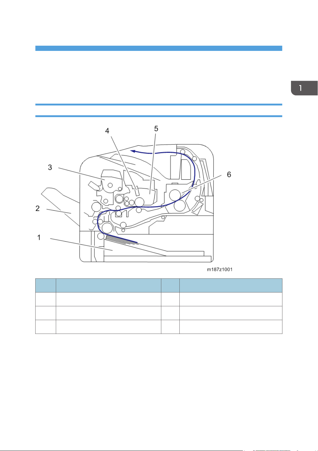
Product Overview
Component Layout
No. Description No. Description
1 Paper Feed Unit 4 LED Head
2 By-pass Tray 5 PCDU
3 Toner Cartridge 6 Fusing Unit
15
Page 18
1. Product Information
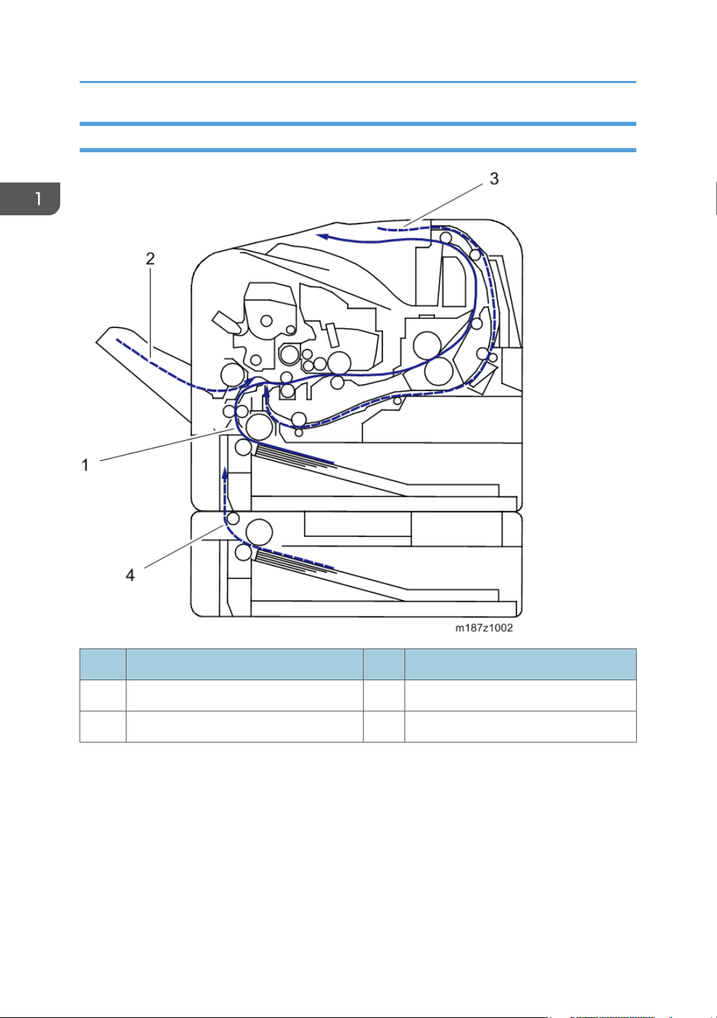
Paper Path
16
No. Description No. Description
1 Main Machine Paper Feed Path 3 Duplex Paper Feed Path
2 By-pass Paper Feed Path 4 Optional Tray Paper Feed Path
Page 19
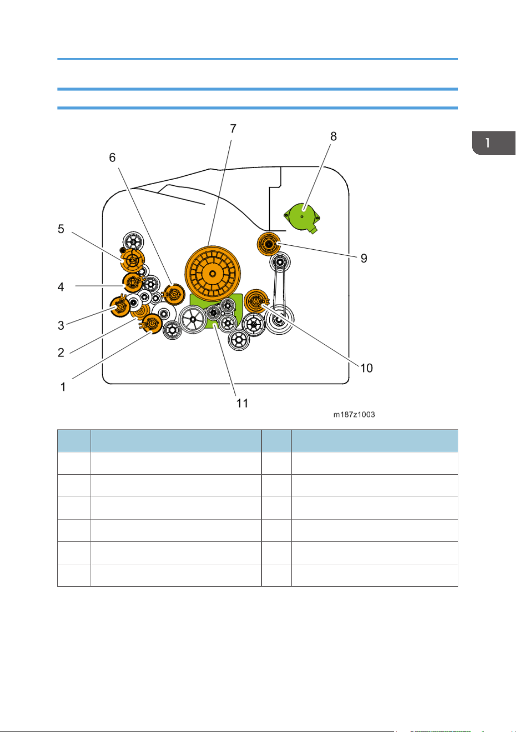
Drive Layout
Product Overview
No. Description No. Description
1 Paper feed clutch 7 Drum Gear
2 Replay Clutch 8 Exit/Reverse Motor
3 By-pass Bottom Plate Clutch 9 Fusing Drive Gear
4 By-pass Feed Clutch 10 Duplex Clutch
5 Toner Supply Clutch 11 Main Motor
6 Registration Clutch
17
Page 20

1. Product Information
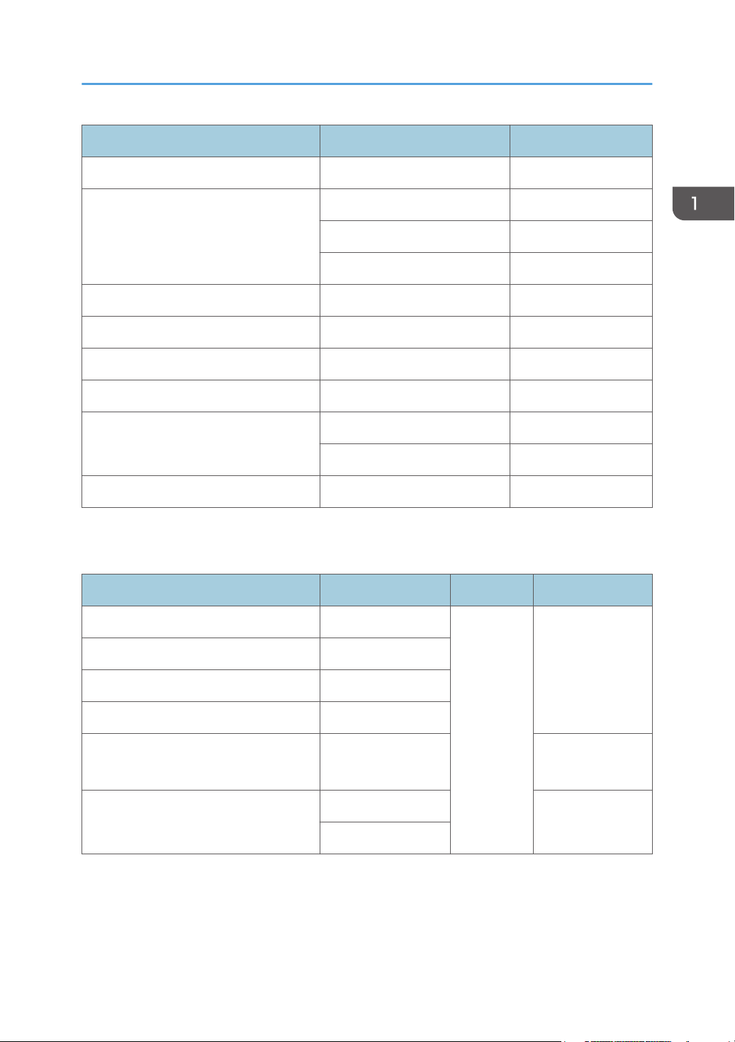
Machine Codes and Peripheral Configuration
Machine Codes and Peripheral Configuration
Main Frame
Item Machine Code Remarks
M187-17 (NA) NEW
SP 6430DN
External Options
No. Item Machine Code Remarks
M187-27 (EU/AA) NEW
M187-21 (CHN) NEW
1 Paper Feed Unit TK2010 M456-17 NEW
Internal Options
IPDS Unit Type P4 M444-50 (NA)
18
Item Machine Code Remarks
M444-51 (EU)
M444-52 (AA/CHN)
Page 21
Item Machine Code Remarks
XPS Direct Print Option Type P4 M444-49
VM CARD Type W *1 M417-19 (NA)
M417-20 (EU)
M417-21 (AA/CHN)
Memory Unit Type N M417-03
SD card for NetWare printing Type P4 M444-55
Hard Disk Drive Option Type P4 M444-42
IEEE802.11 Interface Unit Type O M417-06 (NA)
USB Device Server Option Type M12 D3A7-28 (NA)
D3A7-29 (EU/AA/CHN)
Machine Codes and Peripheral Configuration
IEEE1284 Interface Board Type A B679-17
*1: To install this, Memory Unit Type N and Hard Disk Drive Option Type P4 must first be installed.
Consumables for M187
Item Machine Code Remarks Yield
Print Cartridge SP 6430A M915-17 (NA)
Print Cartridge SP 6430E M915-27 (EU)
Print Cartridge SP 6430S M915-20 (AA)
10,000 pages
(ISO)
Print Cartridge SP 6430C M915-21 (CHN)
NEW
Drum Unit SP 6430
25,000 pages
M919-17
(3P/J)
Maintenance Kit SP 6430 M920-17 (NA)
M920-27 (EU)
90,000 pages
(3P/J)
19
Page 22

1. Product Information
• (ISO): The number of printable pages is based on pages that are compliant with ISO/IEC 19752
with the image density set as the factory default. ISO/IEC 19752 is an international standard for
measurement of printable pages, set by the International Organization for Standardization.
• (6%, 3P/J): A4/Letter 6% test chart, 3 pages/job.
• (3P/J): A4/Letter, 3 pages/job.
20
Page 23

Specifications
See "Appendices" for the following information:
• General Specifications
• Supported Paper Sizes
• Software Accessories
• Optional Equipment
Specifications
21
Page 24

1. Product Information
22
Page 25
2. Installation
Installation Requirements
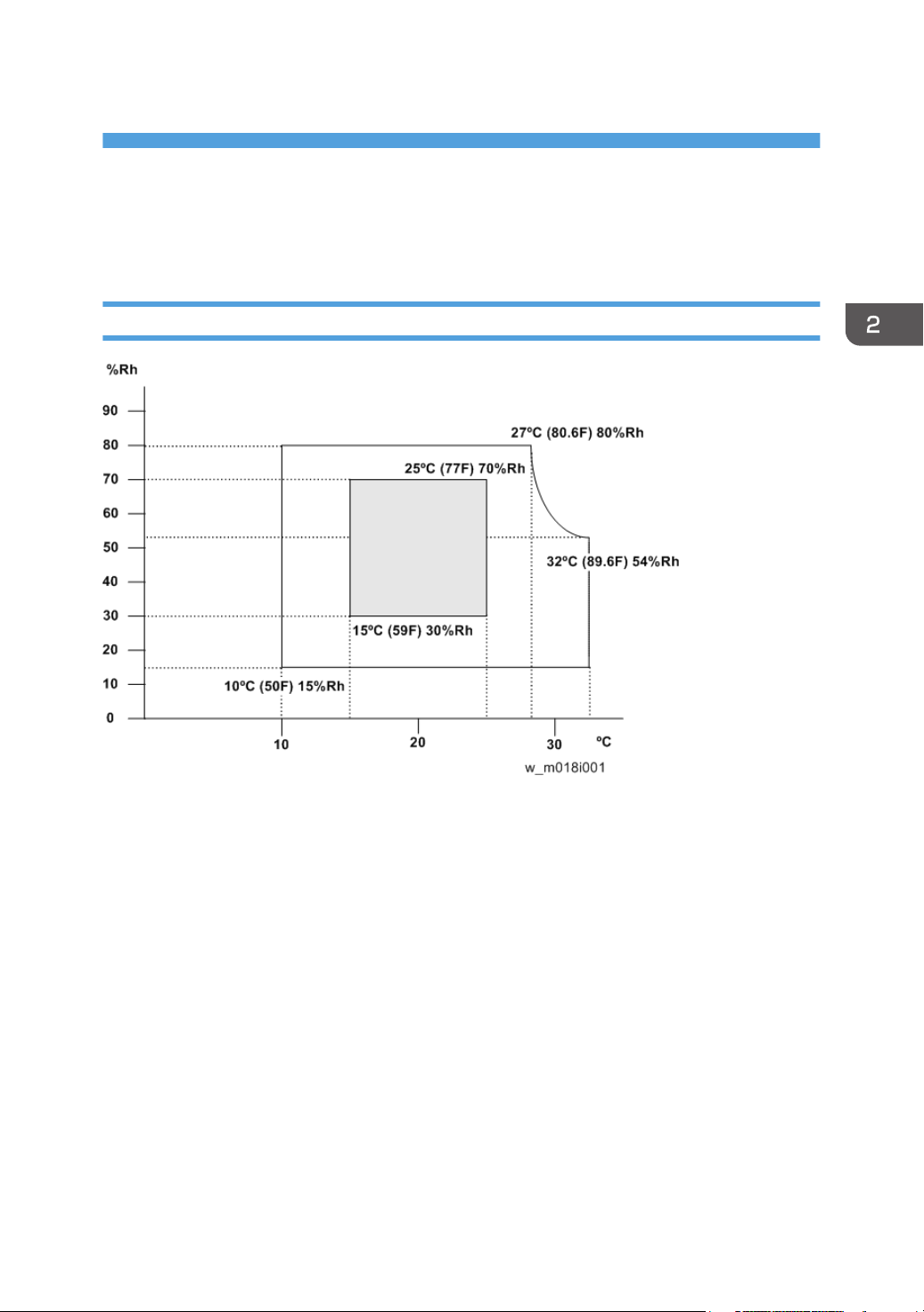
Environment
1. Temperature Range: 10°C to 32°C (50°F to 89.6°F)
2. Humidity Range: 15% to 80% RH
3. Ambient Illumination: Less than 1,500 lux (do not expose to direct sunlight)
4. Ventilation: More than 3 times/hr/person
5. Do not install the machine at locations over 2,000 m (6,562 ft.) above sea level.
23
Page 26
2. Installation
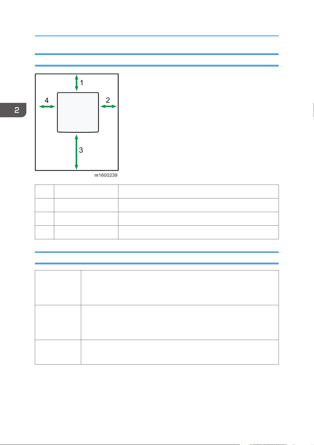
Machine Space Requirements
1 Rear Over 20 cm (7.9 inches)
2 Right Over 10 cm (3.9 inches)
3 Front Over 55 cm (21.7 inches)
4 Left Over 10 cm (3.9 inches)
Machine Dimensions
• Printer only: 459 mm (18.07 inches)
Width
Depth
Height
• With an optional hard disk cover: 475 mm (18.70 inches)
• With Intake louver: 464 mm (18.27 inches)
• 392 mm (15.4 inches)
• With paper feed tray handle: 412 mm (16.22 inches)
• With controller screw: 396.4 mm (15.61 inches)
• Printer Only: 347.5 mm (13.68 inches)
• With optional paper feed trays (TK2010×3): 719.5 mm (28.33 inches)
24
Page 27
Power Requirements
• Make sure that the plug is firmly inserted in the outlet.
• Avoid multi-wiring.
• Be sure to ground the machine.
• Never place anything on the power cord.
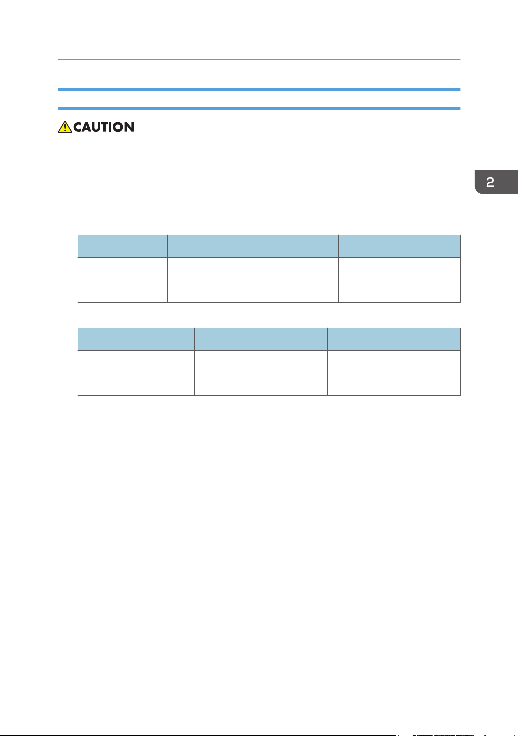
1. Input voltage level:
Destination Power supply voltage Frequency Rated current consumption
NA 120 V to 127 V 60 Hz More than 10 A
EU/AP/CHN 220 V to 240V 50 Hz/60 Hz 5.3 A
2. Permissible voltage fluctuation:
Destination For printing images For operating
Installation Requirements
NA +8.66 / -10% +8.66 / -15%
EU/AP/CHN ±10% ±15%
25
Page 28

2. Installation
Main Machine Installation
• The M187 models are for installation by users.
Accessory Check
Description Q’ty
Power cord 1
Instructions for the Customers
Provide instructions on the following matters to customers. For detailed procedures, see the user
manuals.
• Operating the printer function
• Installing consumables and loading paper
• Operating the main power switch
• Removing jammed paper
• Registering/changing/deleting data in the address book
• Providing precautions on use
• Connecting to computers (such as configuring the port setting)
• Giving a brief outline of the tabs in the drivers
Moving the Machine
• It is dangerous to handle the power cord plug with wet hands. Doing so could result in electric
shock.
• Unplug the power cord from the wall outlet before you move the machine. While moving the
machine, take care that the power cord is not damaged under the machine. Failing to take these
precautions could result in fire or electric shock.
26
Page 29

Main Machine Installation
• If you have to move the machine when the optional paper tray unit is attached, do not push on the
main unit's top section. Doing so can cause the optional paper tray unit to detach, possibly resulting
in injury.
• When disconnecting the power cord from the wall outlet, always pull the plug, not the cord. Pulling
the cord can damage the power cord. Use of damaged power cords could result in fire or electric
shock.
• The machine weighs approximately 22.5 kg (49.6 lb.). When moving the machine, use the inset
grips on both sides, and lift slowly in pairs. The machine will break or cause injury if dropped.
• Do not hold the control panel while moving the machine. Doing so may damage the control panel,
cause a malfunction, or result in injury.
• Be careful when moving the machine. Take the following precautions:
• Close all covers and trays, including the front cover and by-pass tray.
• If optional paper feed units are attached, remove them from the machine and move them
separately.
• Keep the machine level and carry it carefully, taking care not to jolt or tip it. Rough handling may
cause a malfunction or damage the hard disk or memory, resulting in loss of stored files.
1. Be sure to check the following:
The main power switch is turned off.
The power cord is unplugged from the wall outlet.
The interface cable is unplugged from the machine.
2. If any external options are attached, remove them.
3. Lift the machine using the inset grips on both sides of the machine. And then move it
horizontally to the place where you want to use it.
4. If you removed options, reattach them.
• Be sure to move the machine horizontally. To prevent toner from scattering, move the machine
slowly.
27
Page 30

2. Installation
Security Settings
Changing an Administrator's Password
You will be prompted to enter the password when logging in to the printer. No password is set by
default. We strongly recommend you to change the factory default password immediately to prevent
information leakage and unauthorized operations by others.
• For details, see the user manuals. User manual "Security Guide".
Configuring SSL/TLS
To prevent unauthorized viewing, analysis or modification of the data during its transmission, enable
SSL/TLS as required.
• For details, see the user manuals. User manual "Security Guide".
28
Page 31

Paper Feed Unit TK2010
Paper Feed Unit TK2010
• When lifting the machine, use the inset grips on both sides. The machine could break or cause an
injury if dropped.
Component Check
To attach two lower paper trays at the same time, first stack them one upon the other, and then attach
them as a single tray.
Check the quantity and condition of the accessories against the following list.
Paper Feed Unit TK2010 (500 Sheets M456)
No. Description Q’ty
1 Installation Procedure 1
2
Manufacturer Information / Authorized Representative Information
(Paper)
Installation Procedure
• Turn off the main power switch of the copier and unplug the power cord before you start the
installation procedure.
• To attach two lower paper trays at the same time, first stack them one upon the other, and then
attach them as a single unit.
1. Remove the packaging from the lower paper tray.
2. Lift the machine slowly using the inset grips on both sides, and then position it
immediately above the lower paper tray.
1
29
Page 32

2. Installation
3. There are three upright pins on the optional lower paper tray. Align them with the holes
on the underside of the machine, and then carefully lower the machine.
4. Plug in the power cord, and then turn on the machine.
5. Print the configuration page to confirm that the tray was attached correctly.
• Check "Attached Equipment" on the configuration page. If the tray is attached correctly, "Tray 2",
"Tray 3", and "Tray 4" appear.
30
Page 33

USB Device Server Option Type M12
USB Device Server Option Type M12
Component Check
No Items Q’ty
1 Interface board 1
2 USB connector 1
3 Ferrite cores 2
• An Ethernet cable, which is not packed with this option, is required.
Interface Board Surface
No. Item Description
1 Switch Used to reset to the factory settings.
31
Page 34

2. Installation
No. Item Description
2 Ethernet port Used to connect the Ethernet cable.
3 USB port
Used to connect this option to the main machine.
Do not use with other options.
Installation Procedure
• When you install this option to the main machine for the first time, the interface board must be
connected directly to your PC to set up the IP address and other network settings.
1. Turn off the main power switch, and unplug the power cord from the wall socket.
2. Remove the interface slot cover. ( ×2)
32
Page 35

3. Insert the interface board into the interface slot [A] ( ×2).
4. Insert the USB connector into the USB port on this option.
USB Device Server Option Type M12
5. Insert the other side of the USB connector into the USB port B on the main machine.
• The machine shape and/or USB port location differs depending on the machine.
33
Page 36

2. Installation
6. Mount the ferrite cores on the Ethernet cable, while looping the cable at 3 cm (approx.
1.2 inch) [A] from the each end of the cable.
34
Page 37

USB Device Server Option Type M12
RTB 14
Step added
RTB 14
Steps added
7. Insert the Ethernet cable into the Ethernet board on this option.
8. Insert the other end of the Ethernet cable to a PC for network setting.
9. Plug the power cord into the wall socket and turn on the main power switch.
• Do not unplug the USB connector while the machine is recognizing this option. It may take
between 30 seconds to 1 minute to finish recognizing it (the LEDs by the connector light up
when finished; see below). If unplugged, connect the cable again.
What Do the LED Indications Mean?
When this option is properly installed and recognized by the main machine, the LED indicators light up
under the following conditions.
35
Page 38

2. Installation
RTB 14
Replace this
procedure
No. Light Color Lights Up When:
1 Green and Yellow 1000BASE-T operates
2 Green 10BASE-T operates
3 Yellow 100BASE-TX operates
Notes for Energy Save Mode Setting
If the machine that has this option enters into the energy save mode, you cannot print because there will
be a communication error. Follow the instructions below to set the machine to disable entering into the
energy save mode.
1. Press [Features Settings] on the operation panel.
2. Press [Administrator Tools] in [System Settings].
3. Press [Energy Saver Mode to Disable Print Server].
4. Press [Disable Mode].
5. Press [OK].
6. Press [Features Settings].
IP Address Setting
This section describes how to set an IP address on this option manually. Note that you can set an IP
address which is not only on the same network segment but also on a different network segment to share
a single printer with devices in multiple networks.
• You cannot change the IP address for this option from the operation panel of the main machine.
The setting must be done from a web browser on your PC.
• The network setting of this option is initially assigned as follows:
IP address: 192.168.100.100 / Subnet mask: 255.255.255.0
• The network setting of your PC must be in the same network segment to change the network setting
of this option.
1. Make a note of the current network settings of your PC.
2. Change the IP address on your PC to [192.168.100.xxx (*0 - 255)].
3. Change the subnet mask on your PC to [255.255.255.0].
36
4. Open a web browser.
5. Type [http://192.168.100.100/] in the address bar.
Page 39

6. Press the Enter key.
• The setting screen for this option appears.
7. Click [Network Setting].
USB Device Server Option Type M12
8. Type [root] in the user name textbox and click [OK].
9. Input [IP Address], [Subnet Mask] and [Default Gateway].
10. Set other items if needed.
11. Press [Set].
12. Close the web browser.
37
Page 40

2. Installation
13. Disconnect the Ethernet cable from the PC.
14. Connect the Ethernet cable to a network device (e.g. switching hub).
15. Set the IP address of this option in the printer driver that you use.
38
Page 41

SD Card Appli Move
SD Card Appli Move
Overview
Since there are only two SD card slots (one of them is a service slot), three or more SD card applications
cannot be used simultaneously.
However, if multiple SD card applications are merged, three or more SD card options can be used.
This function is referred to as the “SD card merge function.”
The “SD card merge function” is a function which enables the use of three or more functions within the
capacity of two SD cards by physically transferring the function of one SD card to other SD cards (all SD
card options can be stored in two SD cards).
However, SD card applications are under license, therefore, since an SD card license after merge is
transferred to the target SD card, it cannot be used even if it is moved to the target machine.
Also, a process to prevent illegal copying is performed.
The service program "SD Card Appli Move" (SP5-873) lets you move application programs from one
SD card to another SD card.
Notes on Using the SD Merge Function
• The data necessary for authentication is transferred with the application program from an SD card
to another SD card. Authentication fails if you try to use the SD card after you move the application
program from one card to another card.
• Do not use the SD card if it has been used before for other purposes. Normal operation is not
guaranteed when such an SD card is used.
• An SD card, which becomes empty after moving the data in it to another card, cannot be reused.
• After moving the data in an SD card to another card so that the source card becomes empty, keep
the empty card in place by, for example, affixing it near the SD card slot with adhesive tape. This is
done for the following reasons:
• The SD card can be the only proof that the user is licensed to use the application program.
• You may need to check the SD card and its data to solve a problem in the future.
39
Page 42

2. Installation
SD Card Applications
SD Card Option
IPDS Unit Type P1 128M Yes Yes Available for use in
SD card for NetWare printing
Type P1
XPS Direct Print Option Type
P1
Browser Unit Type P1 128M Yes Yes
VM Card Type W 512M No Yes Available for use
• Both Slots 1 and 2 are vacant when the machine is shipped from the factory.
• VM Card Type W cannot be moved to another SD card.
Card Size
Capacity
128M Yes Yes
128M Yes Yes
Movable to
another SD
card
Target SD
card
Remarks
Slot 1 (Upper) and
Slot 2 (Lower)
only in Slot 1
(Upper)
Move Exec
The menu "Move Exec" (SP5-873-001) lets you move application programs from the original SD card
to another SD card.
• Do not turn ON the write protect switch of the system SD card or application SD card on the
machine. If the write protect switch is ON, a download error (e.g. Error Code 44) occurs during a
firmware upgrade or application merge.
1. Turn the main power switch off.
40
Page 43

SD Card Appli Move
2. SD card slot cover [A].
3. Make sure that a target SD card is in SD Card Slot 1 [A]. The application program is
moved to this SD card.
4. Insert the source SD card with the application program in SD Card Slot 2 [B]. The
application program is copied from this source SD card.
5. Turn the main power switch on.
6. Start the SP mode.
7. Select SP5-873-001 "Move Exec".
8. Follow the messages shown on the operation panel.
9. Turn the main power switch off.
10. Remove the source SD card from SD Card Slot 2 [B].
11. Attach the SD card slot cover.
41
Page 44

2. Installation
12. Turn the main power switch on.
13. Check that the application programs run normally.
Undo Exec
"Undo Exec" (SP5-873-002) lets you move back application programs from an SD card in SD Card
Slot 1 (upper) to the original SD card in SD Card Slot 2 (lower). You can use this program when, for
example, you have mistakenly copied some programs by using Move Exec (SP5-873-001).
• Do not turn ON the write protect switch of the system SD card or application SD card on the
machine. If the write protect switch is ON, a download error (e.g. Error Code 44) occurs during a
firmware upgrade or application merge.
1. Turn the main power switch off.
2. SD card slot cover [A].
42
Page 45

3. Insert the integrated SD card in Slot 1 [A].
4. Insert the SD card which became empty after integration in Slot 2 [B].
SD Card Appli Move
5. Turn the main power switch on.
6. Start the SP mode.
7. Select SP5-873-002 "Undo Exec."
8. Follow the messages shown on the operation panel.
9. Exit the SP mode.
10. Remove the SD card from SD Card Slot 2 [B].
11. Turn the main power switch off.
12. Attach the SD card slot cover.
13. Turn the main power switch on.
14. Check that the application has been deleted.
43
Page 46

2. Installation
Settings for @Remote Service
• Prepare and check the following check points before you visit the customer site. For details, ask the
@Remote key person.
Check points before making @Remote settings
1. The setting of SP5-816-201 in the mainframe must be "0".
2. Print the SMC with SP5-990-002 and then check if a device ID2 (SP5-811-003) must be
correctly programmed.
• 6 spaces must be put between the 3-digit prefix and the following 8-digit number (e.g.
xxx______xxxxxxxx).
3. The following settings must be correctly programmed.
4. If a proxy server is available, configure the following SP settings.
• Use Proxy (SP5-816-062) Set to "1: Enable".
• Proxy server IP address (SP5-816-063)
• Proxy server Port number (SP5-816-064)
• Proxy User ID (SP5-816-065)
• Proxy Password (SP5-816-066)
5. Get a Request Number.
Execute the @Remote Settings
1. Enter the SP mode.
2. Input the Request number which you have obtained from @Remote Center GUI, and then
enter [OK] with SP5-816-202.
3. Confirm the Request number, and then click [EXECUTE] with SP5-816-203.
4. Check the confirmation result with SP5-816-204.
Value Meaning Solution/ Workaround
0 Succeeded -
Communication error (proxy
3
enabled)
Check the network condition.
44
Page 47

Settings for @Remote Service
Value Meaning Solution/ Workaround
Communication error (proxy
4
disabled)
Check the network condition.
5 Proxy error (authentication error) Check Proxy user name and password.
6 Communication error Check the network condition.
8 Other error See "SP5-816-208 Error Codes" below this.
Request number confirmation
9
executing
Processing… Please wait.
11 Already registered -
12 Parameter error -
20 Dial-up authentication error
21 Answer tone detection error
22 Carrier detection error
23 Invalid setting value (modem)
* These errors occur only in the modems that
support @Remote.
24 Low power supply current
25 unplugged modem
26 Busy line
5. Make sure that the screen displays the Location Information with SP5-816-205 only when
it has been input at the Center GUI.
6. Click [EXECUTE] to execute the registration with SP5-816-206.
7. Check the registration result with SP5-816-207.
Value Meaning Solution/ Workaround
0 Succeeded -
2 Already registered Check the registration status.
Communication error (proxy
3
enabled)
Check the network condition.
Communication error (proxy
4
disabled)
Check the network condition.
45
Page 48

2. Installation
Value Meaning Solution/ Workaround
5 Proxy error (Authentication error) Check Proxy user name and password.
8 Other error See "SP5-816-208 Error Codes" below this.
Request number confirmation
9
executing
Processing… Please wait.
11 Already registered -
12 Parameter error -
20 Dial-up authentication error
21 Answer tone detection error
22 Carrier detection error
23 Invalid setting value (modem)
* These errors occur only in the modems that
support @Remote.
24 Low power supply current
25 unplugged modem
26 Busy line
46
Page 49

8. Exit the SP mode.
SP5-816-208 Error Codes
Cause Code Meaning Solution/ Workaround
Settings for @Remote Service
Operation Error,
Incorrect Setting
-12002Inquiry, registration attempted
without acquiring Request No.
-12003Attempted registration without
execution of a confirmation and
no previous registration.
-12004Attempted setting with illegal
entries for certification and ID2.
-12005@Remote communication is
prohibited. The device has an
Embedded RC gate-related
problem.
-12006A confirmation request was made
after the confirmation had been
already completed.
-12007The request number used at
registration was different from the
one used at confirmation.
Obtain a Request Number
before attempting the Inquiry
or Registration.
Perform Confirmation before
attempting the Registration.
Check ID2 of the mainframe.
Make sure that "Remote
Service" in User Tools is set to
"Do not prohibit".
Execute registration.
Check Request No.
-1200
Update certification failed
8
because mainframe was in use.
-12009The ID2 in the NVRAM does not
match the ID2 in the individual
certification.
-12010The certification area is not
initialized.
Check the mainframe
condition. If the mainframe is
in use, try again later.
Check ID2 of the mainframe.
Initialize the certification
area.
47
Page 50

2. Installation
Cause Code Meaning Solution/ Workaround
-2385 Other error
-2387 Not supported at the Service
Center
-2389 Database out of service
-2390 Program out of service
Error Caused by
Response from
GW URL
-2391
Two registrations for the same
mainframe
Check the registration
condition of the mainframe
-2392 Parameter error
-2393 External RCG not managed
-2394 Mainframe not managed
-2395 Box ID for external RCG is illegal.
-2396
-2397 Incorrect ID2 format
Mainframe ID for external RCG is
illegal.
Check the ID2 of the
mainframe.
-2398 Incorrect request number format Check the Request No.
48
Page 51

3. Preventive Maintenance
Preventive Maintenance Tables
Preventive Maintenance Tables
See "Appendices" for the following information:
• Preventive Maintenance Items
49
Page 52

3. Preventive Maintenance
Image Quality Standards
Image Quality Standards
Engine
Item Specification Remarks
Leading edge: 4.2 mm (1/6 inches)
Assured Image Area
Magnification Error ±0.75% or less
Perpendicularity ±0.7 mm / 100 mm DLT: 1.75/200 mm or less
Linearity ±0.25 mm / 100 mm
Parallelism ±1.8 mm or less DLT: ±2.0 mm or less
• To check whether the problem is with the image or is due to another issue, print the test pattern.
Left/Right: 4.2 mm (1/6 inches)
Trailing edge: 4.2 mm (1/6 inches)
50
Page 53

Paper Transfer Quality Standards
Paper Transfer Quality Standards
Engines
Item Specification Remarks
Single Side:
Main Scan: 0 ± 2.0 mm
Sub Scan: 0 ± 1.5 mm
Margin position
Back of the paper when performing duplex
printing:
Main Scan: 0 ± 2.0 mm
Sub Scan: 0 ± 1.5 mm
Single Side:
Paper Transfer Quality Standards
± 1.2 mm / 200 mm or less (B5 SEF or
more)
± 1.0 mm / 100 mm or less (Less than B5
Skew
Curling after fusing
These standards are determined using standard paper under standard conditions.
Values may vary depending on environmental conditions such as temperature, humidity, use of used
paper, etc.
SEF)
Duplex:
±1.0 mm/100 mm or less (B5 SEF or more)
±1.5 mm/100 mm or less (Less than B5
SEF)
25 mm or less from leading and trailing
edges
60 mm or less (* applicable for printed
forms over 90 kg in weight)
In an office environment
51
Page 54

3. Preventive Maintenance
52
Page 55

4. Replacement and Adjustment
General Cautions
Notes on the Main Power Switch
The main power button of this machine has been changed to a push-button switch (push button) from the
conventional rocker switch. The push switch has characteristics and specifications different from the
rocker switch. Care must be taken when replacing and adjusting parts.
Characteristics of the Push Switch (DC Switch)
Power is supplied to the machine even when the main power switch is turned OFF.
The push switch in this machine uses DC (direct current). Therefore, if the AC power cord is
connected to an electrical outlet, power is supplied to the controller board, the operation unit and
other modules even when the main power is turned OFF. When replacing the controller board and
the operation unit in this state, not only these boards, it will damage other electrical components.
So, when performing maintenance work such as replacing parts, in addition to turning off the main
power with the push switch, always unplug the AC power cord.
When you disconnect the power cord from the AC wall outlet, inside the machine there is still
residual charge.
When you disconnect the power cord from the AC wall outlet, inside the machine for a while there
is still residual charge. Therefore, if you remove boards in this state, it can cause a blown fuse or
memory failure.
-- How to remove the residual charge inside the machine--
After you unplug the power cord from the AC wall outlet, in order to remove the residual charge
from inside the machine, be sure to press the main power switch. Thus, the charge remaining in the
machine is released, and it is possible to remove boards.
When you reconnect the AC power cord into an AC wall outlet, the machine will start
automatically.
In order to remove the residual charge, push the main power switch while you disconnect the AC
power cord. At that time, the power ON flag inside the machine is set. Therefore, after you finish
work on the machine and reconnect the power cord to the AC, even if you do not press the main
power switch, the machine will start automatically and the moving parts will begin to move. When
working on moving parts, be careful that fingers or clothes do not get caught.
53
Page 56

4. Replacement and Adjustment
• Automatic restart deals with cases when you accidentally unplugged the AC power cord or
unexpected power outages. By keeping the power flag ON, after the resumption of power, the
machine will start up automatically.
In rare cases, when you reconnect the AC power cord to a power outlet, the machine does not start
automatically. In this case, the machine has not failed. The cause is due to the timing of releasing the
residual charge. If you press the main power switch while the residual charge was already released, the
power ON flag will not be set. At this time, start the machine manually by pressing the main power
switch.
Shutdown Method
1. Press the main power switch [A] on the left side of the machine.
After the shutdown process, the main power is turned off automatically.
When the shutdown is complete
Operation panel LED: Off
2. Take out the power cord.
3. Wait 3 minutes (this is the time required if you will remove the rear cover and access the
interior of the machine, to take out the controller board for example).
Note: If some LEDs on any of the boards are blinking or lit, current is still flowing.
How to start from shutdown
To start the machine, press the main power switch. However, if you press the main power switch
between the beginning and the end of a shutdown, the machine will not start.
54
Page 57

General Cautions
Forced Shutdown
In case normal shutdown does not complete for some reason, the machine has a forced shutdown
function.
To make a forced shutdown, press and hold the main power switch for 6 seconds.
In general, do not use the forced shutdown.
• Forced shutdown may damage the hard disk and memory, and can cause damage to the machine.
Use a forced shutdown only if it is unavoidable.
55
Page 58

4. Replacement and Adjustment
Special Tools
Part Number Description Q’ty
B6455010 SD Card 128MB 1
B6455020 SD Card 1GB 1
• A PC (Personal Computer) is required for creating the Encryption key file on an SD card when
replacing the controller board for a model in which HDD encryption has been enabled.
56
Page 59

Exterior Covers
Front Cover
1. Paper Feed Tray (page 107)
2. By-pass tray (page 66)
3. Push the release button to open the front cover [A].
Exterior Covers
4. Hanging wire [A]
57
Page 60

4. Replacement and Adjustment
5. Release the hinges at both ends, and detach the front cover [A].
• To remove the front cover, lift the left hinge first to release while raising the front cover
upwards.
• The left hinge is C-cut.
Left Cover
• There is a tab on the back of the left cover. Refer to the picture below.
58
Page 61

1. Open the front cover [A].
2. Two screws securing the front side of the left cover [A] ( ×2)
Exterior Covers
3. Open the rear cover [A].
59
Page 62

4. Replacement and Adjustment
4. Two screws securing the rear side of the left cover [B] ( ×2)
5. One screw to detach the left cover ( ×1)
60
Right Cover
• There is a tab on the back of the right cover. Refer to the picture below.
Page 63

1. Open the front cover [A].
Exterior Covers
61
Page 64

4. Replacement and Adjustment
2. Two screws securing the front side of the right cover [A] ( ×2)
3. Open the rear cover [A].
4. Two screws securing the rear side of the right cover [B] ( ×2)
62
5. Right cover [A] ( ×1)
Page 65

6. Memory cover [B]
Rear Cover, Rear Lower Cover
1. Left cover (page 58)
Exterior Covers
2. Right cover (page 60)
3. Open the rear cover [A].
63
Page 66

4. Replacement and Adjustment
4. Screw ( ×1)
5. Release the stopper [A].
64
Page 67

6. Release the hinges at both ends to detach the rear cover [A].
Exterior Covers
• To release the hinges, push the left hinge inside with your finger while holding the rear cover
[A] open at angle of approx. 10°. The right hinge is removed spontaneously when the left
hinge is released.
7. Rear lower cover [A] (
×4)
65
Page 68

4. Replacement and Adjustment
By-pass Tray
1. Open the by-pass tray [A].
2. Release the hinges at both ends.
66
Page 69

3. Release the hinges at both ends of by-pass tray [A] to detach it.
• To remove the by-pass tray, lift the left hinge first to release while raising the by-pass tray
upwards.
• The left hinge is C-cut.
Exterior Covers
Upper Cover
1. Left cover (page 58)
2. Right cover (page 60)
3. Operation panel (page 68)
67
Page 70

4. Replacement and Adjustment
4. Upper cover [A] ( ×4)
Operation Panel
1. Open the front cover [A].
68
Page 71

2. Release the tabs of the operation panel [A] (Tab×2).
3. The connector on the back of the operation panel [A] ( ×2)
Exterior Covers
4. Remove the screws and connector ( ×5, ×1).
69
Page 72

4. Replacement and Adjustment
5. OPU board [A] ( ×1)
6. Board cover [A] (Tab×2)
70
7. Panel [A]
Page 73

8. Eco night sensor [A]
Exterior Covers
71
Page 74

4. Replacement and Adjustment
LED Optics
• Turn off the main power switch and disconnect the power cord before you start any of the
procedures in this section. (page 53)
LED Unit
• Be sure to clean the lens of the LED head after replacing the LED unit or if you inadvertently touch
the lens when replacing another unit.
1. PCDU (page 78)
2. Upper Cover (page 67)
3. LED cover [A] ( ×2, Tab ×3)
72
Page 75

4. Rotate the LED unit [A] until locked.
5. Ground wire [A] and FFC [B] from the LED unit.
LED Optics
73
Page 76

4. Replacement and Adjustment
6. Unlock the levers at both ends of the LED unit, and rotate the LED unit [A] back to the
original position.
7. Spacer [A] from the LED unit.
74
Page 77

8. Two screws that secure the front stay [A] ( ×2).
LED Optics
9. Widen the side plate slightly and pull out the LED unit [A] from the main machine.
• When installing the LED unit, fit the shaft (upper) of the LED unit into the holes of the LED unit
holder.
75
Page 78

4. Replacement and Adjustment
10. Bend the stay [A] to release the left and right tabs, and then separate the stay from the
LED head [B] (Tab ×4).
76
Page 79

11. Pull out two spring holders from the LED head [A].
LED Optics
77
Page 80

4. Replacement and Adjustment
PCDU
PCDU
1. Press the release button and open the front cover [A].
2. Hold the grip to pull the PCDU [A] out.
78
Page 81

Toner Cartridge
Toner Cartridge
1. Open the front cover [A].
Toner Cartridge
2. Push down the release lever [A] of the toner cartridge.
• The release lever works in two steps. To release the lock, push down the release lever to the
horizontal position.
79
Page 82

4. Replacement and Adjustment
3. Hold the grip to pull the toner cartridge [A] out.
80
Page 83

Image Transfer
Image Transfer Roller
1. PCDU (page 78)
2. Pinch both green ends of the guide [A] and pull it towards you.
Image Transfer
3. Image transfer roller [A]
• When installing the image transfer roller, do the following procedure:
81
Page 84

4. Replacement and Adjustment
1. Attach the image transfer roller to the fitting points at both ends of the guide plate [A].
2. Lay down the guide plate [B], on which the image transfer roller [A] is installed, until it clicks
into place.
82
Page 85

Drive Unit
• Turn off the main power switch and disconnect the power cord before you start any of the
procedures in this section (page 53).
Main Motor
The main motor is located behind the drive unit.
1. BCU (page 137)
2. Drive Unit (page 89)
Drive Unit
3. Bracket [A] (
4. Four gears [A]
×3)
83
Page 86

4. Replacement and Adjustment
5. Main Motor [A] ( ×3)
Exit/Reverse Motor
1. Upper Cover (page 67)
2. Controller Board (page 134)
3. Bracket [A] ( ×4)
84
Page 87

4. Harness guide [A] ( ×1, ×1, Tab×2)
5. Exit/Reverse Motor [A] ( ×2, ×1, ×1)
Drive Unit
• Slide the exit/reverse motor towards the right side, and then pull out the motor.
85
Page 88

4. Replacement and Adjustment
Registration Clutch
1. BCU (page 137)
2. Registration Clutch [A] ( ×1, ×1, ×2)
Paper Feed Clutch
1. BCU (page 137)
2. Harness Guide [A] ( ×1, ×3)
• When installing the harness guide, clamp the harness at the same positions as before removal.
86
Page 89

3. Paper feed clutch [A] ( ×1, ×1)
Drive Unit
By-pass Feed Clutch
1. Right Cover (page 60)
87
Page 90

4. Replacement and Adjustment
2. Harness Guide [A] ( ×1, ×3)
• When installing the harness guide, clamp the harness at the same positions as before removal.
88
3. By-pass Feed Clutch [A] ( ×1, ×1)
Page 91

By-pass Bottom Plate Clutch
1. Right Cover (page 60)
2. By-pass Bottom Plate Clutch [A] ( ×1, ×1, ×1)
Drive Unit
Drive Unit
1. BCU (page 137)
2. PCDU cooling fan with duct (page 141)
3. Drive Unit [A] ( ×4, ×1, ×1)
Gear Unit
1. BCU (page 137)
2. Registration clutch (page 86)
3. By-pass bottom plate clutch (page 89)
4. Paper feed clutch (page 86)
89
Page 92

4. Replacement and Adjustment
5. By-pass feed clutch (page 87)
6. Drive unit (page 89)
7. Paper Size Detection Switch (page 117)
8. Temp Humid Sensor (page 147)
9. Gear bracket [A] ( ×1)
10. Gear [A]
90
Page 93

11. Gear Unit [A] ( ×4, Ground plate [B], ×1, ×1)
• Gears Arrangement:
Drive Unit
• Note when reassembling the gear unit [A]:
Close the front cover first, and then fit the boss [B] of the front cover arm into the opening [C].
91
Page 94

4. Replacement and Adjustment
Toner Supply Clutch
1. Gear Unit (page 89)
2. Clip ring ( ×1)
92
3. Gear [A]
Page 95

4. Toner Supply Clutch [B] with shaft
5. Toner supply clutch [A] (Gear ×1, Shaft ×1)
Drive Unit
Relay Clutch
1. Gear Unit (page 89)
93
Page 96

4. Replacement and Adjustment
2. Relay Clutch [A] ( ×1, ×1, ×1)
Duplex Clutch
1. Controller Board (page 134)
2. Bracket [A] (
×4)
94
Page 97

3. Duplex Clutch [A] ( ×1, ×2, ×1)
Junction Gate Solenoid
1. Upper Cover (page 67)
Drive Unit
2. Junction gate solenoid [A] ( ×2, ×1, ×1)
95
Page 98

4. Replacement and Adjustment
Fusing
• Because there is a danger of burns on contact with hot parts of the fusing unit, start work when the
temperature drops to a low enough temperature.
• Turn off the main power switch and disconnect the power cord before you start any of the
procedures in this section (page 53).
Fusing Unit
1. Open the rear cover [A].
96
Page 99

2. Release the lock levers [A].
Fusing
3. Fusing Unit [A]
• If replacing a used fusing unit for Emergency Maintenance (EM), you must reset the PM counter. Be
sure to use a fusing unit that does not include the new-unit detection.
• For Preventive Maintenance (PM), use a fusing unit that includes the new-unit detection. The PM
counter is reset automatically and is not inherited after replacement. Also, the counters for image
transfer roller, paper feed roller and friction pad are reset by the new-unit detection.
97
Page 100

4. Replacement and Adjustment
Upper Fusing Unit, Lower Fusing Unit
1. Fusing Unit (page 96)
2. Four screws of the fusing unit [A] ( ×4)
3. Cover [A] ( ×1)
98
 Loading...