

Page 1

MVI-ADMNET
'C' Programmable
'C' Programmable Application
Development Module with Ethernet
February 20, 2013
DEVELOPER'S GUIDE
Page 2

Your Feedback Please
We always want you to feel that you made the right decision to use our products. If you have suggestions, comments,
compliments or complaints about our products, documentation, or support, please write or call us.
ProSoft Technology
5201 Truxtun Ave., 3rd Floor
Bakersfield, CA 93309
+1 (661) 716-5100
+1 (661) 716-5101 (Fax)
www.prosoft-technology.com
support@prosoft-technology.com
Copyright © 2013 ProSoft Technology, Inc., all rights reserved.
MVI-ADMNET Developer's Guide
February 20, 2013
ProSoft Technology ®, ProLinx ®, inRAx ®, ProTalk ®, and RadioLinx ® are Registered Trademarks of ProSoft
Technology, Inc. All other brand or product names are or may be trademarks of, and are used to identify products
and services of, their respective owners.
In an effort to conserve paper, ProSoft Technology no longer includes printed manuals with our product shipments.
User Manuals, Datasheets, Sample Ladder Files, and Configuration Files are provided on the enclosed CD-ROM,
and are available at no charge from our web site: www.prosoft-technology.com.
Content Disclaimer
This documentation is not intended as a substitute for and is not to be used for determining suitability or reliability of
these products for specific user applications. It is the duty of any such user or integrator to perform the appropriate
and complete risk analysis, evaluation and testing of the products with respect to the relevant specific application or
use thereof. Neither ProSoft Technology nor any of its affiliates or subsidiaries shall be responsible or liable for
misuse of the information contained herein. Information in this document including illustrations, specifications and
dimensions may contain technical inaccuracies or typographical errors. ProSoft Technology makes no warranty or
representation as to its accuracy and assumes no liability for and reserves the right to correct such inaccuracies or
errors at any time without notice. If you have any suggestions for improvements or amendments or have found errors
in this publication, please notify us.
No part of this document may be reproduced in any form or by any means, electronic or mechanical, including
photocopying, without express written permission of ProSoft Technology. All pertinent state, regional, and local safety
regulations must be observed when installing and using this product. For reasons of safety and to help ensure
compliance with documented system data, only the manufacturer should perform repairs to components. When
devices are used for applications with technical safety requirements, the relevant instructions must be followed.
Failure to use ProSoft Technology software or approved software with our hardware products may result in injury,
harm, or improper operating results. Failure to observe this information can result in injury or equipment damage.
© 2013 ProSoft Technology. All rights reserved.
Printed documentation is available for purchase. Contact ProSoft Technology for pricing and availability.
North America: +1.661.716.5100
Asia Pacific: +603.7724.2080
Europe, Middle East, Africa: +33 (0) 5.3436.87.20
Page 3

Latin America: +1.281.298.9109
Important Installation Instructions
Power, Input, and Output (I/O) wiring must be in accordance with Class I, Division 2 wiring methods, Article 501-4 (b)
of the National Electrical Code, NFPA 70 for installation in the U.S., or as specified in Section 18-1J2 of the Canadian
Electrical Code for installations in Canada, and in accordance with the authority having jurisdiction. The following
warnings must be heeded:
A WARNING - EXPLOSION HAZARD - SUBSTITUTION OF COMPONENTS MAY IMPAIR SUITABILITY FOR
CLASS I, DIV. 2;
B WARNING - EXPLOSION HAZARD - WHEN IN HAZARDOUS LOCATIONS, TURN OFF POWER BEFORE
REPLACING OR WIRING MODULES
C WARNING - EXPLOSION HAZARD - DO NOT DISCONNECT EQUIPMENT UNLESS POWER HAS BEEN
SWITCHED OFF OR THE AREA IS KNOWN TO BE NON-HAZARDOUS.
D THIS DEVICE SHALL BE POWERED BY CLASS 2 OUTPUTS ONLY.
MVI (Multi Vendor Interface) Modules
WARNING - EXPLOSION HAZARD - DO NOT DISCONNECT EQUIPMENT UNLESS POWER HAS BEEN
SWITCHED OFF OR THE AREA IS KNOWN TO BE NON-HAZARDOUS.
AVERTISSEMENT - RISQUE D'EXPLOSION - AVANT DE DÉCONNECTER L'ÉQUIPEMENT, COUPER LE
COURANT OU S'ASSURER QUE L'EMPLACEMENT EST DÉSIGNÉ NON DANGEREUX.
Warnings
North America Warnings
A Warning - Explosion Hazard - Substitution of components may impair suitability for Class I, Division 2.
B Warning - Explosion Hazard - When in Hazardous Locations, turn off power before replacing or rewiring
modules.
Warning - Explosion Hazard - Do not disconnect equipment unless power has been switched off or the area is
known to be nonhazardous.
C Suitable for use in Class I, division 2 Groups A, B, C and D Hazardous Locations or Non-Hazardous Locations.
ATEX Warnings and Conditions of Safe Usage:
Power, Input, and Output (I/O) wiring must be in accordance with the authority having jurisdiction
A Warning - Explosion Hazard - When in hazardous locations, turn off power before replacing or wiring modules.
B Warning - Explosion Hazard - Do not disconnect equipment unless power has been switched off or the area is
known to be non-hazardous.
C These products are intended to be mounted in an IP54 enclosure. The devices shall provide external means to
prevent the rated voltage being exceeded by transient disturbances of more than 40%. This device must be used
only with ATEX certified backplanes.
D DO NOT OPEN WHEN ENERGIZED.
Electrical Ratings
Backplane Current Load: 800 mA @ 5 V DC; 3mA @ 24V DC
Operating Temperature: 0 to 60°C (32 to 140°F)
Storage Temperature: -40 to 85°C (-40 to 185°F)
Shock: 30g Operational; 50g non-operational; Vibration: 5 g from 10 to 150 Hz
Relative Humidity 5% to 95% (non-condensing)
All phase conductor sizes must be at least 1.3 mm(squared) and all earth ground conductors must be at least
4mm(squared).
Page 4

CE
EMC-EN61326-1:2006; EN6100-6-4:2007
CSA/cUL
C22.2 No. 213-1987
CSA CB Certified
IEC61010
ATEX
EN60079-0 Category 3, Zone 2
EN60079-15
243333
ME06
ANSI / ISA
ISA 12.12.01 Class I Division 2, GPs A, B, C, D
CSA/cUL
C22.2 No. 213-1987
CSA CB Certified
IEC61010
ATEX
EN60079-0 Category 3, Zone 2
EN60079-15
243333
Markings - MVI56, MVI69, PTQ
Markings - MVI46, MVI71
Warning: This module is not hot-swappable! Always remove power from the rack before inserting or removing this
module, or damage may result to the module, the processor, or other connected devices.
Battery Life Advisory
The MVI46, MVI56, MVI56E, MVI69, and MVI71 modules use a rechargeable Lithium Vanadium Pentoxide battery to
backup the real-time clock and CMOS. The battery should last for the life of the module. The module must be
powered for approximately twenty hours before the battery becomes fully charged. After it is fully charged, the battery
provides backup power for the CMOS setup and the real-time clock for approximately 21 days. When the battery is
fully discharged, the module will revert to the default BIOS and clock settings.
Note: The battery is not user replaceable.
Page 5

MVI-ADMNET ♦ 'C' Programmable Contents
'C' Programmable Application Development Module with Ethernet Developer's Guide
Contents
Your Feedback Please ........................................................................................................................ 2
Content Disclaimer .............................................................................................................................. 2
Important Installation Instructions ....................................................................................................... 3
MVI (Multi Vendor Interface) Modules ................................................................................................ 3
Warnings ............................................................................................................................................. 3
Battery Life Advisory ........................................................................................................................... 4
1 Introduction 9
1.1 Operating System .................................................................................................... 10
2 Preparing the MVI-ADMNET Module 11
2.1 Package Contents ................................................................................................... 12
2.2 Jumper Locations and Settings ............................................................................... 13
2.2.1 Setup Jumper .......................................................................................................... 13
2.2.2 Port 1 and Port 2 Jumpers ...................................................................................... 13
2.3 Connections ............................................................................................................ 14
2.3.1 MVI-ADMNET Communication Ports ...................................................................... 14
3 Setting Up Your Development Environment 15
3.1 Setting Up Your Compiler........................................................................................ 16
3.1.1 Configuring Digital Mars C++ 8.49 .......................................................................... 16
3.1.2 Configuring Borland C++5.02 .................................................................................. 25
3.2 ROM Disk Configuration.......................................................................................... 33
3.2.1 CONFIG.SYS File ................................................................................................... 33
3.2.2 Command Interpreter .............................................................................................. 35
3.2.3 Sample ROM Disk Image ........................................................................................ 35
3.3 Creating a ROM Disk Image ................................................................................... 37
3.3.1 WINIMAGE: Windows Disk Image Builder .............................................................. 37
3.4 Downloading a ROM Disk Image ............................................................................ 39
3.4.1 MVIUPDAT .............................................................................................................. 39
3.5 MVI System BIOS Setup ......................................................................................... 41
3.6 Transferring Files to and from the Module with HyperTerminal .............................. 43
3.6.1 Required Software ................................................................................................... 43
3.6.2 Connecting to the Module ....................................................................................... 44
3.6.3 Enabling the Console .............................................................................................. 45
3.6.4 Installing RY.exe and SY.exe .................................................................................. 49
3.6.5 Downloading Files From a PC to the ADM Module ................................................ 49
3.6.6 Uploading files from the ADM module to a PC........................................................ 50
3.7 Installing and Configuring the Module ..................................................................... 52
3.7.1 Using Side-Connect (Requires Side-Connect Adapter) (MVI71) ............................ 52
4 Understanding the MVI-ADMNET API 55
4.1 API Libraries ............................................................................................................ 56
4.1.1 Calling Convention .................................................................................................. 56
ProSoft Technology, Inc. Page 5 of 122
February 20, 2013
Page 6

Contents MVI-ADMNET ♦ 'C' Programmable
Developer's Guide 'C' Programmable Application Development Module with Ethernet
4.1.2 Header File ............................................................................................................. 56
4.1.3 Sample Code .......................................................................................................... 56
4.1.4 Multi-threading Considerations ............................................................................... 57
4.2 Development Tools ................................................................................................. 58
4.3 Theory of Operation ................................................................................................ 59
4.3.1 ADM API ................................................................................................................. 59
4.3.2 ADMNET API Architecture ...................................................................................... 59
4.4 ADM API Files......................................................................................................... 60
4.4.1 ADM Interface Structure ......................................................................................... 60
5 Application Development Function Library - ADMNET API 63
5.1 ADMNET API Functions ......................................................................................... 64
5.2 ADMNET API Initialize Functions ........................................................................... 65
ADM_init_socket ......................................................................................................................... 65
ADM_open_sk ............................................................................................................................. 66
ADM_init_UDP_buffer ................................................................................................................. 67
5.3 ADMNET API Release Socket Functions ............................................................... 68
ADM_release_sockets ................................................................................................................ 68
ADM_close_sk ............................................................................................................................ 69
5.4 ADMNET API Send Socket Functions .................................................................... 70
ADM_send_socket ...................................................................................................................... 70
ADM_send_sk ............................................................................................................................. 71
5.5 ADMNET API Receive Socket Functions ............................................................... 72
ADM_receive_socket .................................................................................................................. 72
ADM_receive_sk ......................................................................................................................... 73
ADM_receive_buffered_UDP_sk ................................................................................................ 74
5.6 ADMNET API Miscellaneous Functions ................................................................. 75
ADM_NET_GetVersionInfo ......................................................................................................... 75
ADM_is_sk_open ........................................................................................................................ 76
6 WATTCP API Functions 77
6.1 WATTCP API Functions ......................................................................................... 78
6.2 ADMNET API Initialize Functions ........................................................................... 80
sock_init ....................................................................................................................................... 80
6.3 ADMNET API System Functionality ....................................................................... 81
tcp_tick ........................................................................................................................................ 81
tcp_open ...................................................................................................................................... 82
tcp_open_fast .............................................................................................................................. 83
udp_open..................................................................................................................................... 84
udp_open_fast ............................................................................................................................. 85
resolve ......................................................................................................................................... 86
sock_mode .................................................................................................................................. 87
sock_established ......................................................................................................................... 88
ip_timer_init ................................................................................................................................. 89
ip_timer_expired .......................................................................................................................... 90
set_timeout .................................................................................................................................. 91
chk_timeout ................................................................................................................................. 92
sockerr ......................................................................................................................................... 93
sockstate ..................................................................................................................................... 94
gethostid ...................................................................................................................................... 95
6.4 ADMNET API Release Socket Functions ............................................................... 96
Page 6 of 122 ProSoft Technology, Inc.
February 20, 2013
Page 7

MVI-ADMNET ♦ 'C' Programmable Contents
'C' Programmable Application Development Module with Ethernet Developer's Guide
sock_exit ...................................................................................................................................... 96
sock_abort ................................................................................................................................... 97
sock_close ................................................................................................................................... 98
6.5 ADMNET API Send Socket Functions .................................................................... 99
sock_write .................................................................................................................................... 99
sock_fastwrite ............................................................................................................................ 100
sock_flush .................................................................................................................................. 101
sock_flushnext ........................................................................................................................... 102
sock_puts ................................................................................................................................... 103
sock_putc ................................................................................................................................... 104
6.6 ADMNET API Receive Socket Functions .............................................................. 105
sock_read .................................................................................................................................. 105
sock_fastread ............................................................................................................................. 106
tcp_listen .................................................................................................................................... 107
sock_gets ................................................................................................................................... 108
sock_getc ................................................................................................................................... 109
sock_dataready .......................................................................................................................... 110
rip ............................................................................................................................................... 111
inet_ntoa .................................................................................................................................... 112
inet_addr .................................................................................................................................... 113
7 Support, Service & Warranty 115
7.1 Contacting Technical Support ............................................................................... 115
7.2 Warranty Information ............................................................................................. 116
Glossary of Terms 117
Index 121
ProSoft Technology, Inc. Page 7 of 122
February 20, 2013
Page 8

Contents MVI-ADMNET ♦ 'C' Programmable
Developer's Guide 'C' Programmable Application Development Module with Ethernet
Page 8 of 122 ProSoft Technology, Inc.
February 20, 2013
Page 9

MVI-ADMNET ♦ 'C' Programmable Introduction
In This Chapter
Operating System .................................................................................. 10
'C' Programmable Application Development Module with Ethernet Developer's Guide
1 Introduction
This document provides information needed to develop application programs for
the MVI ADM Ethernet Serial Communication Module. The MVI suite of modules
is designed to allow devices with a serial and Ethernet port to be accessed by a
PLC. The modules and their corresponding platforms are as follows:
MVI46: 1746 (SLC)
MVI56: 1756 (ControlLogix)
MVI69: 1769 (CompactLogix)
MVI71: 1771 (PLC)
The modules are programmable to accommodate devices with unique SerialEthernet protocols.
This document includes information about the available ethernet communication
software API libraries, programming information, and example code. For tools,
module configuration, serial communication software API, serial communication
programming information, and example code for both the module and the PLC,
refer to MVI ADM Developer’s Guide.
This document assumes the reader is familiar with software development in the
16-bit DOS environment using the 'C' programming language. This document
also assumes that the reader is familiar with Rockwell Automation programmable
controllers and the PLC platform.
ProSoft Technology, Inc. Page 9 of 122
February 20, 2013
Page 10

Introduction MVI-ADMNET ♦ 'C' Programmable
Developer's Guide 'C' Programmable Application Development Module with Ethernet
1.1 Operating System
The MVI module includes General Software Embedded DOS 6-XL. This
operating system provides DOS compatibility along with real-time multitasking
functionality. The operating system is stored in Flash ROM and is loaded by the
BIOS when the module boots.
DOS compatibility allows user applications to be developed using standard DOS
tools, such as Digital Mars and Borland compilers. User programs may be
executed automatically by loading them from either the CONFIG.SYS file or an
AUTOEXEC.BAT file. In addition to MVI-ADMNET, ADMTCP.CFG is required to
assign an IP address to the module. Users can store the ADMTCP.CFG file
directly to a Compact Flash.
The format of the ADMTCP.CFG is as follows:
# ProSoft Technology
# Default private class 3 address
my_ip=192.168.0.148
# Default class 3 network mask
netmask=255.255.255.0
# name server 1 up to 9 may be included
# nameserver=xxx.xxx.xxx.xxx
# name server 2
# nameserver=xxx.xxx.xxx.xxx
# The gateway I wish to use
gateway=192.168.0.1
# some networks (class 2) require all three parameters
# gateway,network,subnetmask
# gateway 192.168.0.1,192.168.0.0,255.255.255.0
# The name of my network
# domainslist="mynetwork.name"
Note: DOS programs that try to access the video or keyboard hardware directly will not function
correctly on the MVI module. Only programs that use the standard DOS and BIOS functions to
perform console I/O are compatible.
Page 10 of 122 ProSoft Technology, Inc.
February 20, 2013
Page 11

MVI-ADMNET ♦ 'C' Programmable Preparing the MVI-ADMNET Module
In This Chapter
Package Contents ................................................................................. 12
Jumper Locations and Settings ............................................................. 13
Connections .......................................................................................... 14
'C' Programmable Application Development Module with Ethernet Developer's Guide
2 Preparing the MVI-ADMNET Module
ProSoft Technology, Inc. Page 11 of 122
February 20, 2013
Page 12

Preparing the MVI-ADMNET Module MVI-ADMNET ♦ 'C' Programmable
Developer's Guide 'C' Programmable Application Development Module with Ethernet
2.1 Package Contents
Your MVI-ADMNET package includes:
MVI-ADMNET Module
ProSoft Technology Solutions CD-ROM (includes all documentation, sample
code, and sample ladder logic).
Null Modem Cable
Mini-DIN to DB-9 Cable
Page 12 of 122 ProSoft Technology, Inc.
February 20, 2013
Page 13

MVI-ADMNET ♦ 'C' Programmable Preparing the MVI-ADMNET Module
'C' Programmable Application Development Module with Ethernet Developer's Guide
2.2 Jumper Locations and Settings
Each module has three jumpers:
Setup
Port 1
Port 2
2.2.1 Setup Jumper
The Setup jumper, located at the bottom of the module, should have the two pins
jumpered when programming the module. Once programmed, the jumper should
be removed.
2.2.2 Port 1 and Port 2 Jumpers
These jumpers, located at the bottom of the module, configure the port settings
to RS-232, RS-422, or RS-485. By default, the jumpers for both ports are set to
RS-232. These jumpers must be set properly before using the module.
ProSoft Technology, Inc. Page 13 of 122
February 20, 2013
Page 14

Preparing the MVI-ADMNET Module MVI-ADMNET ♦ 'C' Programmable
Developer's Guide 'C' Programmable Application Development Module with Ethernet
2.3 Connections
2.3.1 MVI-ADMNET Communication Ports
The MVI-ADMNET module has three physical connectors: two application ports
and one debugging port, with an RJ45 plug and Ethernet port located on the front
of the module.
Page 14 of 122 ProSoft Technology, Inc.
February 20, 2013
Page 15

MVI-ADMNET ♦ 'C' Programmable Setting Up Your Development Environment
In This Chapter
Setting Up Your Compiler ...................................................................... 16
ROM Disk Configuration ........................................................................ 33
Creating a ROM Disk Image .................................................................. 37
Downloading a ROM Disk Image .......................................................... 39
MVI System BIOS Setup ....................................................................... 41
Transferring Files to and from the Module with HyperTerminal ............. 43
Installing and Configuring the Module ................................................... 52
'C' Programmable Application Development Module with Ethernet Developer's Guide
3 Setting Up Your Development Environment
ProSoft Technology, Inc. Page 15 of 122
February 20, 2013
Page 16

Setting Up Your Development Environment MVI-ADMNET ♦ 'C' Programmable
Developer's Guide 'C' Programmable Application Development Module with Ethernet
3.1 Setting Up Your Compiler
There are some important compiler settings that must be set in order to
successfully compile an application for the MVI platform. The following topics
describe the setup procedures for each of the supported compilers.
3.1.1 Configuring Digital Mars C++ 8.49
The following procedure allows you to successfully build the sample ADM code
supplied by ProSoft Technology using Digital Mars C++ 8.49. After verifying that
the sample code can be successfully compiled and built, you can modify the
sample code to work with your application.
Note: This procedure assumes that you have successfully installed Digital Mars C++ 8.49 on your
workstation.
Downloading the Sample Program
The sample code files are located in the ADM_TOOL_MVI.ZIP file. This zip file is
available from the CD-ROM shipped with your system or from the
www.prosoft-technology.com web site. When you unzip the file, you will find the
sample code files in \ADM_TOOL_MVI\SAMPLES\.
Important: The sample code and libraries in the 1756-MVI-Samples folder are not compatible with,
and are not supported for, the Digital Mars compiler.
Building an Existing Digital Mars C++ 8.49 ADM Project
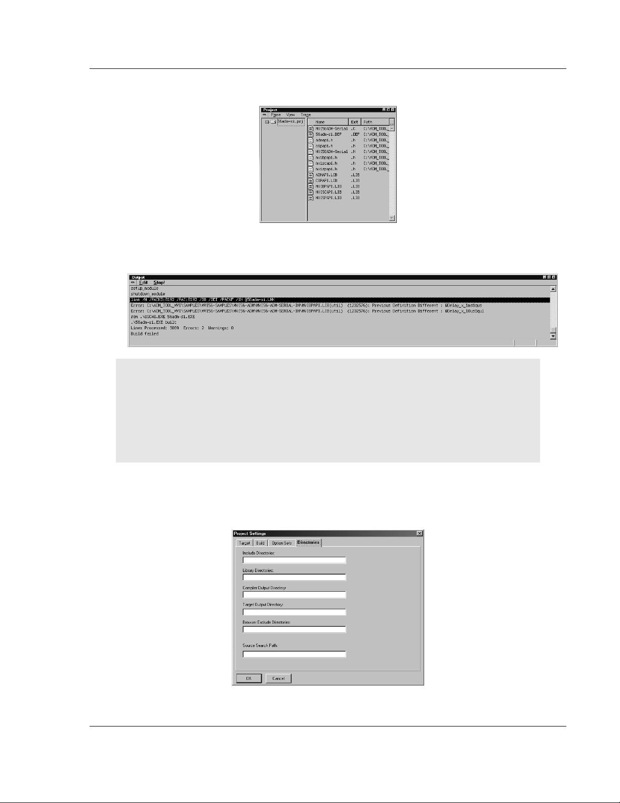
1 Start Digital Mars C++ 8.49, and then click Project Open from the Main
Menu.
2 From the Folders field, navigate to the folder that contains the project
(C:\ADM_TOOL_MVI\SAMPLES\…).
3 In the File Name field, click on the project name (56adm-si.prj).
Page 16 of 122 ProSoft Technology, Inc.
February 20, 2013
Page 17
MVI-ADMNET ♦ 'C' Programmable Setting Up Your Development Environment
'C' Programmable Application Development Module with Ethernet Developer's Guide
4 Click OK. The Project window appears:
5 Click Project Rebuild All from the Main Menu to create the .exe file. The
status of the build will appear in the Output window:
Porting Notes: The Digital Mars compiler classifies duplicate library names as Level 1 Errors
rather than warnings. These errors will manifest themselves as "Previous Definition Different:
function name". Level 1 errors are non-fatal and the executable will build and run. The architecture
of the ADM libraries will cause two or more of these errors to appear when the executable is built.
This is a normal occurrence. If you are building existing code written for a different compiler you
may have to replace calls to run-time functions with the Digital Mars equivalent. Refer to the Digital
Mars documentation on the Run-time Library for the functions available.
6 The executable file will be located in the directory listed in the Compiler
Output Directory field. If it is blank then the executable file will be located in
the same folder as the project file. The Project Settings window can be
accessed by clicking Project Settings from the Main Menu.
ProSoft Technology, Inc. Page 17 of 122
February 20, 2013
Page 18
Setting Up Your Development Environment MVI-ADMNET ♦ 'C' Programmable
Developer's Guide 'C' Programmable Application Development Module with Ethernet
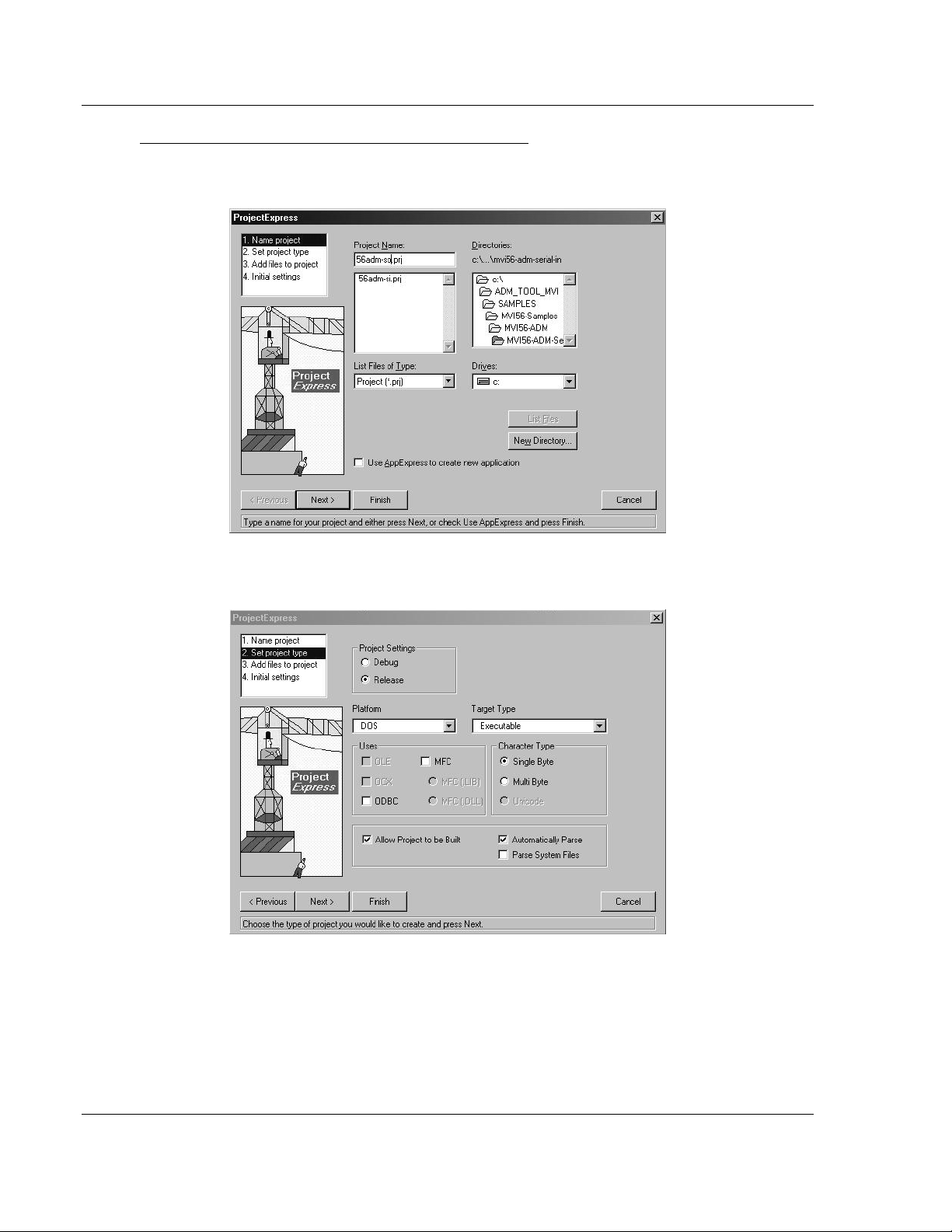
Creating a New Digital Mars C++ 8.49 ADM Project
1 Start Digital Mars C++ 8.49, and then click Project New from the Main
Menu.
2 Select the path and type in the Project Name.
3 Click Next.
4 In the Platform field, choose DOS.
5 In the Project Settings choose Release if you do not want debug information
included in your build.
Page 18 of 122 ProSoft Technology, Inc.
February 20, 2013
Page 19
MVI-ADMNET ♦ 'C' Programmable Setting Up Your Development Environment
'C' Programmable Application Development Module with Ethernet Developer's Guide
6 Click Next.
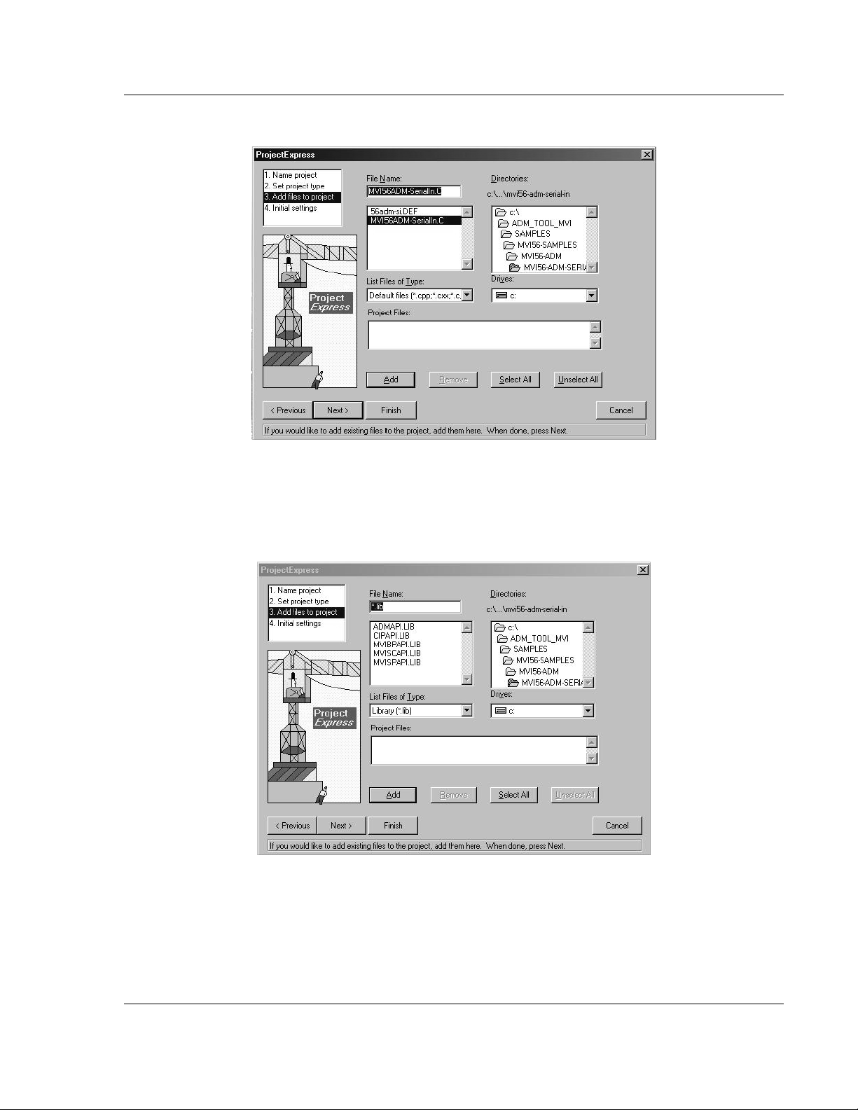
7 Select the first source file necessary for the project.
8 Click Add.
9 Repeat this step for all source files needed for the project.
10 Repeat the same procedure for all library files (.lib) needed for the project.
11 Choose Libraries (*.lib) from the List Files of Type field to view all library files:
ProSoft Technology, Inc. Page 19 of 122
February 20, 2013
Page 20
Setting Up Your Development Environment MVI-ADMNET ♦ 'C' Programmable
Developer's Guide 'C' Programmable Application Development Module with Ethernet
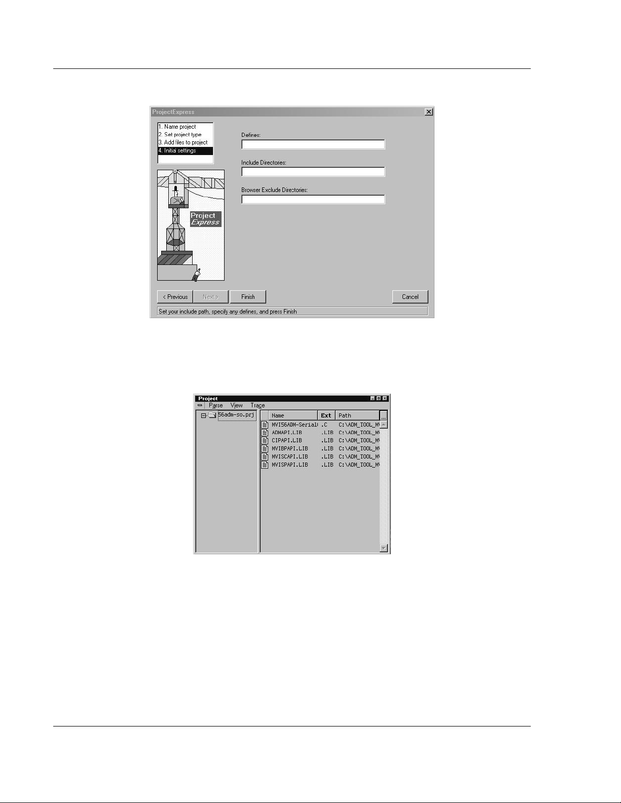
12 Click Next.
13 Add any defines or include directories desired.
14 Click Finish.
15 The Project window should now contain all the necessary source and library
files as shown in the following window:
Page 20 of 122 ProSoft Technology, Inc.
February 20, 2013
Page 21
MVI-ADMNET ♦ 'C' Programmable Setting Up Your Development Environment
'C' Programmable Application Development Module with Ethernet Developer's Guide
16 Click Project Settings from the Main Menu.
17 These settings were set when the project was created. No changes are
required. The executable must be built as a DOS executable in order to run
on the MVI platform.
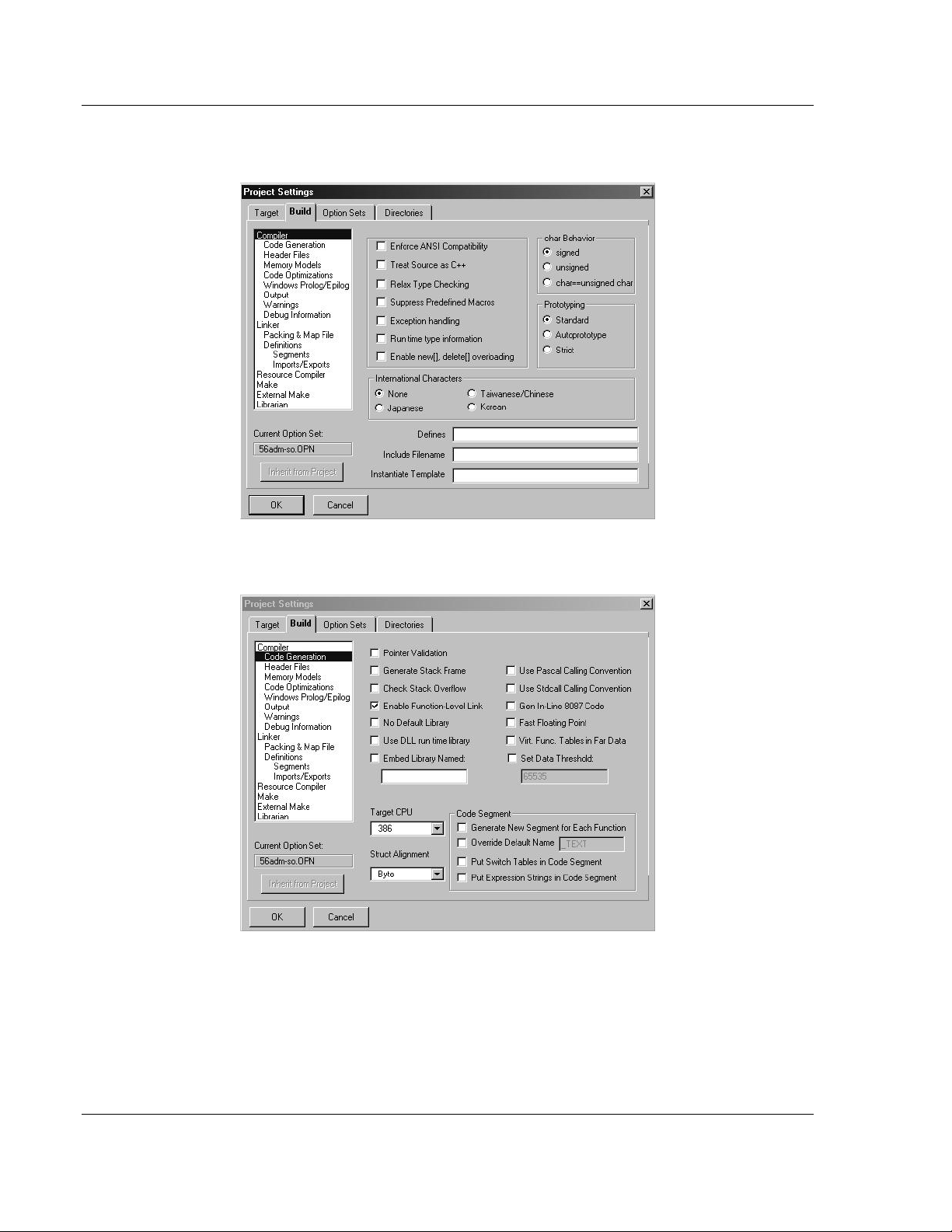
18 Click the Directories tab and fill in directory information as required by your
project’s directory structure.
19 If the fields are left blank then it is assumed that all of the files are in the
same directory as the project file. The output files will be placed in this
directory as well.
ProSoft Technology, Inc. Page 21 of 122
February 20, 2013
Page 22
Setting Up Your Development Environment MVI-ADMNET ♦ 'C' Programmable
Developer's Guide 'C' Programmable Application Development Module with Ethernet
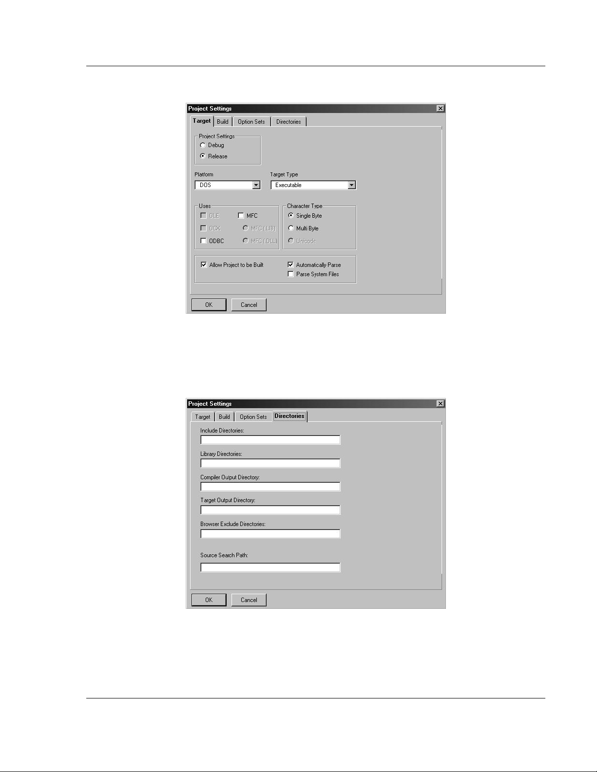
20 Click on the Build tab, and choose the Compiler selection. Confirm that the
settings match those shown in the following screen:
21 Click Code Generation from the Topics field and ensure that the options
match those shown in the following screen:
Page 22 of 122 ProSoft Technology, Inc.
February 20, 2013
Page 23
MVI-ADMNET ♦ 'C' Programmable Setting Up Your Development Environment
'C' Programmable Application Development Module with Ethernet Developer's Guide
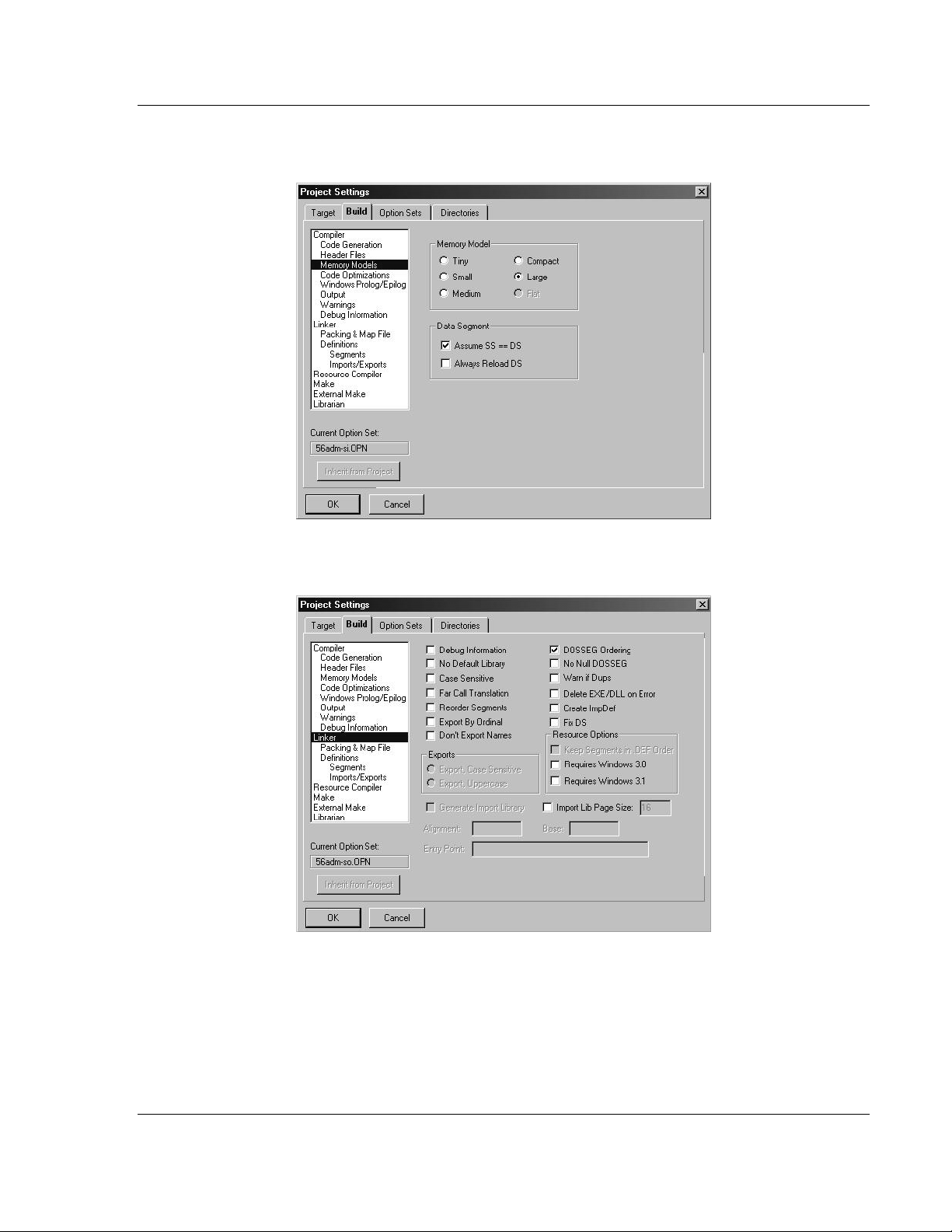
22 Click Memory Models from the Topics field and ensure that the options
match those shown in the following screen:
23 Click Linker from the Topics field and ensure that the options match those
shown in the following screen:
ProSoft Technology, Inc. Page 23 of 122
February 20, 2013
Page 24
Setting Up Your Development Environment MVI-ADMNET ♦ 'C' Programmable
Developer's Guide 'C' Programmable Application Development Module with Ethernet
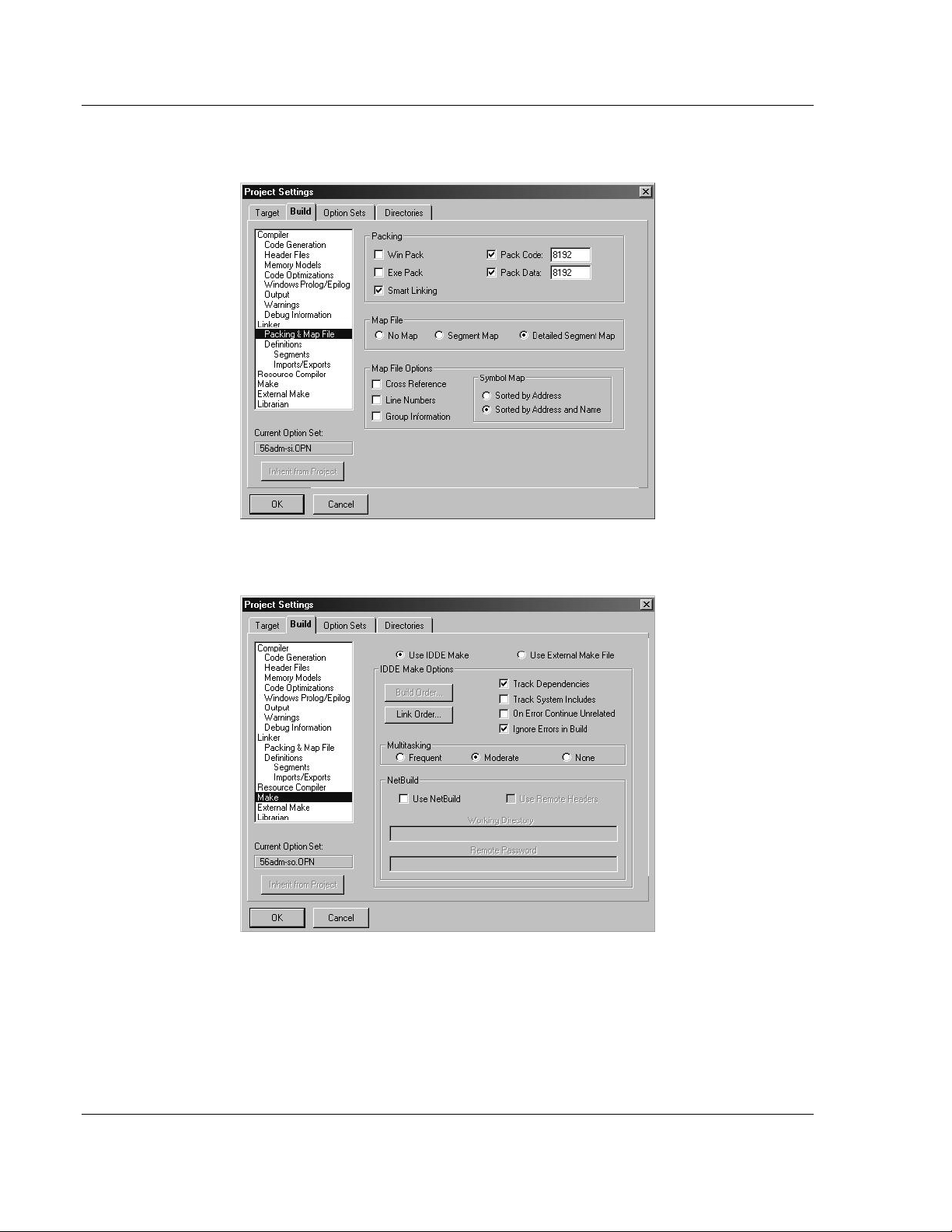
24 Click Packing & Map File from the Topics field and ensure that the options
match those shown in the following screen:
25 Click Make from the Topics field and ensure that the options match those
shown in the following screen:
26 Click OK.
27 Click Parse Update All from the Project Window Menu. The new settings
may not take effect unless the project is updated and reparsed.
28 Click Project Build All from the Main Menu.
Page 24 of 122 ProSoft Technology, Inc.
February 20, 2013
Page 25

MVI-ADMNET ♦ 'C' Programmable Setting Up Your Development Environment
'C' Programmable Application Development Module with Ethernet Developer's Guide
29 When complete, the build results will appear in the Output window:
The executable file will be located in the directory listed in the Compiler Output
Directory box of the Directories tab (that is, C:\ADM_TOOL_MVI\SAMPLES\…).
The Project Settings window can be accessed by clicking Project Settings
from the Main Menu.
Porting Notes: The Digital Mars compiler classifies duplicate library names as Level 1 Errors
rather than warnings. These errors will manifest themselves as "Previous Definition Different:
function name". Level 1 errors are non-fatal and the executable will build and run. The architecture
of the ADM libraries will cause two or more of these errors to appear when the executable is built.
This is a normal occurrence. If you are building existing code written for a different compiler you
may have to replace calls to run-time functions with the Digital Mars equivalent. Refer to the Digital
Mars documentation on the Run-time Library for the functions available.
3.1.2 Configuring Borland C++5.02
The following procedure allows you to successfully build the sample ADM code
supplied by ProSoft Technology, using Borland C++ 5.02. After verifying that the
sample code can be successfully compiled and built, you can modify the sample
code to work with your application.
Note: This procedure assumes that you have successfully installed Borland C++ 5.02 on your
workstation.
Downloading the Sample Program
The sample code files are located in the ADM_TOOL_MVI.ZIP file. This zip file is
available from the CD-ROM shipped with your system or from the
www.prosoft-technology.com web site. When you unzip the file, you will find the
sample code files in \ADM_TOOL_MVI\SAMPLES\.
Important: The sample code and libraries in the 1756-MVI-Samples folder are not compatible with,
and are not supported for, the Digital Mars compiler.
ProSoft Technology, Inc. Page 25 of 122
February 20, 2013
Page 26
Setting Up Your Development Environment MVI-ADMNET ♦ 'C' Programmable
Developer's Guide 'C' Programmable Application Development Module with Ethernet
Building an Existing Borland C++ 5.02 ADM Project
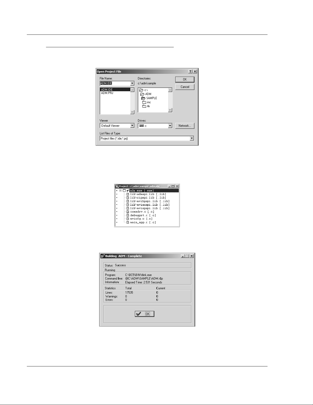
1 Start Borland C++ 5.02, then click Project Open Project from the Main
Menu.
2 From the Directories field, navigate to the directory that contains the project
(C:\adm\sample).
3 In the File Name field, click on the project name (adm.ide).
4 Click OK. The Project window appears:
5 Click Project Build All from the Main Menu to create the .exe file. The
Building ADM window appears when complete:
6 When Success appears in the Status field, click OK.
Page 26 of 122 ProSoft Technology, Inc.
February 20, 2013
Page 27
MVI-ADMNET ♦ 'C' Programmable Setting Up Your Development Environment
'C' Programmable Application Development Module with Ethernet Developer's Guide
The executable file will be located in the directory listed in the Final field of
the Output Directories (that is, C:\adm\sample). The Project Options window
can be accessed by clicking Options Project Menu from the Main Menu.
Creating a New Borland C++ 5.02 ADM Project
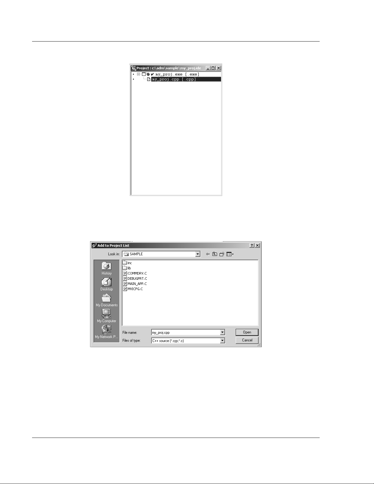
1 Start Borland C++ 5.02, and then click File Project from the Main Menu.
2 Type in the Project Path and Name. The Target Name is created
automatically.
3 In the Target Type field, choose Application (.exe).
4 In the Platform field, choose DOS (Standard).
5 In the Target Model field, choose Large.
6 Ensure that Emulation is checked in the Math Support field.
ProSoft Technology, Inc. Page 27 of 122
February 20, 2013
Page 28
Setting Up Your Development Environment MVI-ADMNET ♦ 'C' Programmable
Developer's Guide 'C' Programmable Application Development Module with Ethernet
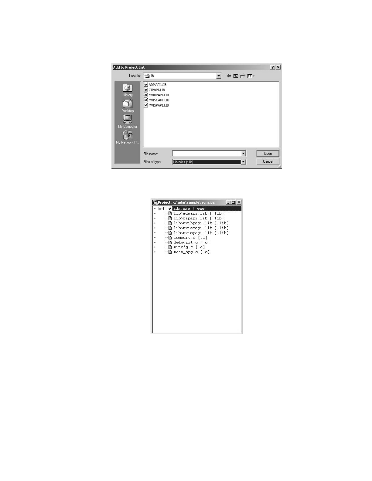
7 Click OK. A Project window appears:
8 Click on the .cpp file created and press the Delete key. Click Yes to delete
the .cpp file.
9 Right click on the .exe file listed in the Project window and choose the Add
Node menu selection. The following window appears:
10 Click source file, then click Open to add source file to the project. Repeat this
step for all source files needed for the project.
11 Repeat the same procedure for all library files (.lib) needed for the project.
Page 28 of 122 ProSoft Technology, Inc.
February 20, 2013
Page 29
MVI-ADMNET ♦ 'C' Programmable Setting Up Your Development Environment
'C' Programmable Application Development Module with Ethernet Developer's Guide
12 Choose Libraries (*.lib) from the Files of Type field to view all library files:
13 The Project window should now contain all the necessary source and library
files as shown in the following window:
ProSoft Technology, Inc. Page 29 of 122
February 20, 2013
Page 30
Setting Up Your Development Environment MVI-ADMNET ♦ 'C' Programmable
Developer's Guide 'C' Programmable Application Development Module with Ethernet
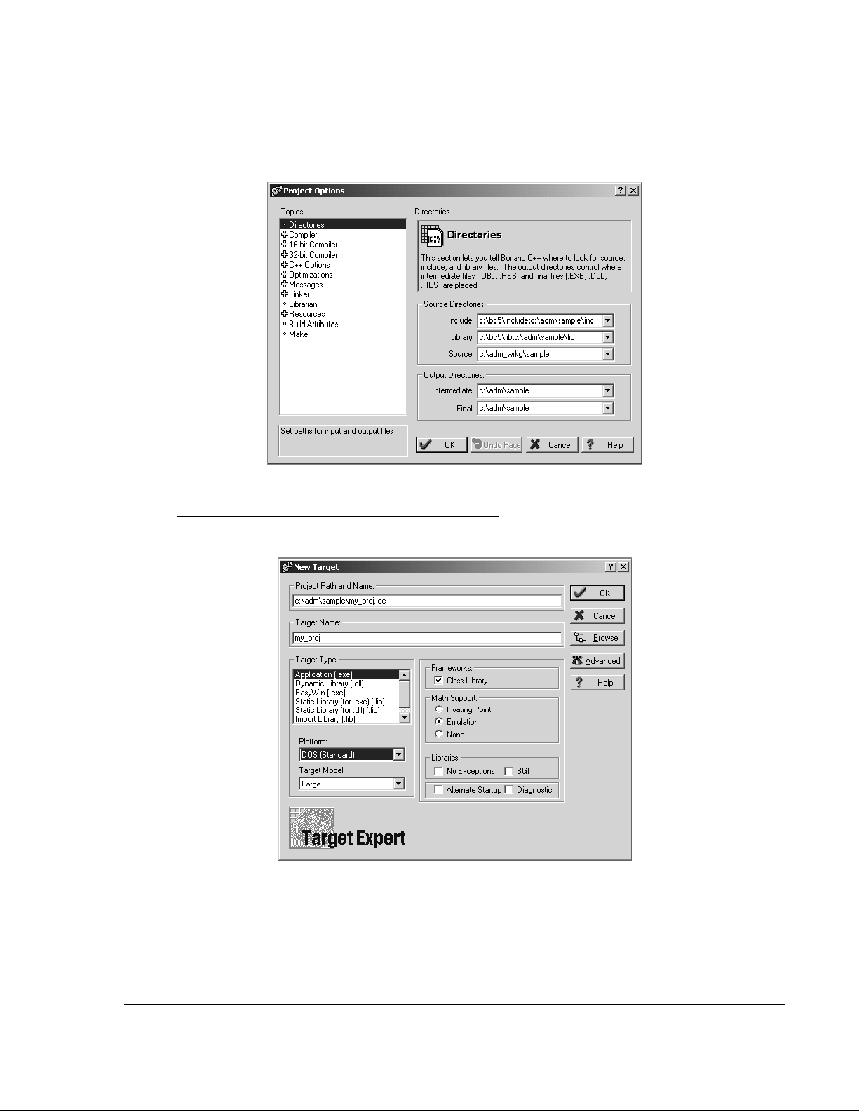
14 Click Options Project from the Main Menu.
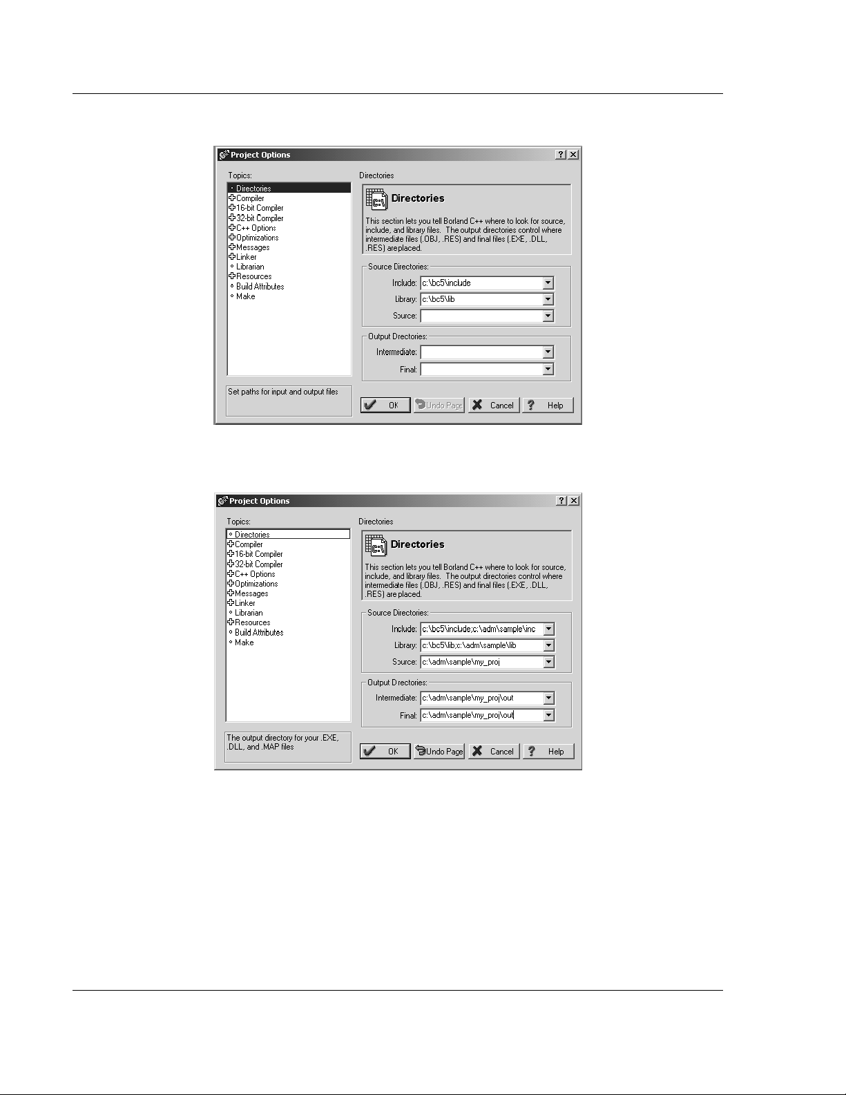
15 Click Directories from the Topics field and fill in directory information as
required by your project’s directory structure.
Page 30 of 122 ProSoft Technology, Inc.
February 20, 2013
Page 31

MVI-ADMNET ♦ 'C' Programmable Setting Up Your Development Environment
'C' Programmable Application Development Module with Ethernet Developer's Guide
16 Double-click on the Compiler header in the Topics field, and choose the
Processor selection. Confirm that the settings match those shown in the
following screen:
17 Click Memory Model from the Topics field and ensure that the options match
those shown in the following screen:
18 Click OK.
19 Click Project Build All from the Main Menu.
ProSoft Technology, Inc. Page 31 of 122
February 20, 2013
Page 32

Setting Up Your Development Environment MVI-ADMNET ♦ 'C' Programmable
Developer's Guide 'C' Programmable Application Development Module with Ethernet
20 When complete, the Success window appears:
21 Click OK. The executable file will be located in the directory listed in the Final
box of the Output Directories (that is, C:\adm\sample). The Project Options
window can be accessed by clicking Options Project from the Main
Menu.
Page 32 of 122 ProSoft Technology, Inc.
February 20, 2013
Page 33

MVI-ADMNET ♦ 'C' Programmable Setting Up Your Development Environment
Module Type
Disk Size
MVI46
896K bytes
MVI56
896K bytes
MVI69
896K bytes
MVI71
896K bytes
MVI94
384K bytes
Module Type
File Name
MVI46
MVI46BP.EXE
MVI56
MVI56BP.EXE & MVI56DD.EXE
MVI69
MVI69BP.EXE
MVI71
MVI71BP.EXE
MVI94
MVI94BP.EXE
'C' Programmable Application Development Module with Ethernet Developer's Guide
3.2 ROM Disk Configuration
User programs are stored in the MVI-ADMNET module’s ROM disk. This disk is
actually a portion of Flash ROM that appears as Drive A:.
The ROM disk size is:
This section describes the contents of the ROM disk.
Along with the user application, the ROM disk image must also contain, at a
minimum, a CONFIG.SYS file and the backplane device driver file.
If a command interpreter is needed, it should also be included.
3.2.1 CONFIG.SYS File
The following lines should always be present in your CONFIG.SYS file:
MVI46
IRQPRIORITY=1
INSTALL=A:\MVI46bp.exe -iomix=0 -class=4 -m0size=3000 -m1size=10000
Note: The MVI46 driver file is called MVI46BP.EXE, and may be loaded from the CONFIG.SYS or
AUTOEXEC.BAT files. The driver must be loaded before executing an application which uses the
MVI API.
The SLC platform supports several classes of modules. The MVI46 can be
configured as a Class 1 or Class 4 module. Also, the I/O image sizes are
configurable. If the MVI46 is configured as Class 4, M0 and M1 files are
supported and their sizes are configurable.
ProSoft Technology, Inc. Page 33 of 122
February 20, 2013
Page 34

Setting Up Your Development Environment MVI-ADMNET ♦ 'C' Programmable
Developer's Guide 'C' Programmable Application Development Module with Ethernet
Note: Messaging is only supported when the MVI46 is Class 4.
To configure the class of the MVI46, use the command line options shown below
when loading the MVI driver MVI46BP.EXE. If no options are given, the MVI46
MVI driver defaults to Class 4, 32 words of I/O, and M0 and M1 sizes of 1024
words (module ID = 13635).
[C:\]MVI46bp -?
MVI46 MVI Driver V1.00
Copyright (c) 2000 Online Development, Inc.
Usage:
C:\MVI46bp.EXE [-iomix=n] [-class=n] [-m0size=n] [-m1size=n]
where:
- iomix=n sets the I/O image sizes. Valid values for n are:
0 => 2 words of IO 5 => 12 words of IO
1 => 4 words of IO 6 => 16 words of IO
2 => 6 words of IO 7 => 24 words of IO
3 => 8 words of IO 8 => 32 words of IO (default)
4 => 10 words of IO
- class=n sets the module class. Valid values for n are:
1 => Class 1 (Messaging disabled)
4 => Class 4 (Messaging enabled, default)
- m0size=n sets the number of words for the Messaging
receive buffer, default m0size=1024
- m1size=n sets the number of words for the Messaging
send buffer, default m1size=1024
NOTE: m0size + m1size must be less than 16320 words.
When configuring the Host Controller for the MVI46, the programming software
requires the Module ID for each module in the system. The Module ID for the
MVI46 depends upon the configuration set by the driver. When the driver is
loaded, it prints to the console the Module ID value that can be entered into the
programming software for the Host Controller. For example, the default
configuration prints the following information:
[C:\]MVI46bp
MVI46 MVI Driver V1.00
Copyright (c) 2000 Online Development, Inc.
1746 MVI Configuration
---------------------Class 4
IO mix 8 = 32 words of IO
M0 File size = 1024 words
M1 File size = 1024 words
SLC Module ID = 13635
The first line, IRQPRIORITY=1, assigns the highest interrupt priority to the I/O
backplane interrupt. The next line loads the backplane device driver. In this
example, the backplane device driver file (MVI46BP.EXE) must be located in the
root directory of the ROM disk. In the case of the MVI46, the module I/O is set
when the backplane driver is loaded. The module is set to class 4 with a 3000
word M0 file and a 10000 word M1 file. The Module ID for installing and
configuring the module in the ladder program will be printed to the console when
the backplane driver is loaded.
Page 34 of 122 ProSoft Technology, Inc.
February 20, 2013
Page 35

MVI-ADMNET ♦ 'C' Programmable Setting Up Your Development Environment
'C' Programmable Application Development Module with Ethernet Developer's Guide
If a command interpreter is needed, a line like the following should be included in
CONFIG.SYS:
SHELL=A:\TINYCMD.COM /s /p
If a command interpreter is not needed, the user application may be executed
directly from the CONFIG.SYS file as shown (where USERAPP.EXE is the user
application executable file name):
SHELL=A:\USERAPP.EXE
The user application may also be executed automatically from an
AUTOEXEC.BAT file, or manually from the console command line. In either
case, a command interpreter (page 35) must be loaded.
MVI56
IRQPRIORITY=1
INSTALL=A:\MVI56bp.exe
INSTALL=A:\MVI56dd.exe
MVI69
IRQPRIORITY=1
SYSTEMPOOL=16384
STACKS=5
SHELL=A:\TINYCMD.COM /s /p
INSTALL=A:\MVI69bp.exe
Note: At this time, messaging is not supported on the MVI69.
MVI71
IRQPRIORITY=1
INSTALL=A:\MVI71bp.exe
MVI94
IRQPRIORITY=1
INSTALL=A:\MVI94bp.exe
3.2.2 Command Interpreter
A command interpreter is needed if you want the module to boot to a command
prompt, or if you want to execute an AUTOEXEC.BAT file. Two command
interpreters are included, a full-featured COMMAND.COM, and the smaller, more
limited TINYCMD.COM. Refer to the General Software Embedded DOS 6-XL
Developer's Guide located on the MVI CD-ROM for more information.
3.2.3 Sample ROM Disk Image
The sample ROM disk image that is included with the MVI-ADMNET module
contains the following files:
ProSoft Technology, Inc. Page 35 of 122
February 20, 2013
Page 36

Setting Up Your Development Environment MVI-ADMNET ♦ 'C' Programmable
File Name
Description
AUTOEXEC.BAT
Runs the executable at startup
CONFIG.SYS
Loads the backplane device driver and the command interpreter
TINYCMD.COM
Command interpreter
MVI46BP.EXE
Backplane device driver
ADMNET46.EXE
Sample application
File Name
Description
AUTOEXEC.BAT
Runs the executable at startup
CONFIG.SYS
Loads the backplane device driver and the command interpreter
TINYCMD.COM
Command interpreter
MVI56BP.EXE
Backplane device driver
MVI56DD.EXE
Backplane device driver
ADMNET56.EXE
Sample application
File Name
Description
AUTOEXEC.BAT
Runs the executable at startup
CONFIG.SYS
Loads the backplane device driver and the command interpreter
TINYCMD.COM
Command interpreter
MVI69BP.EXE
Backplane device driver
ADMNET69.EXE
Sample application
File Name
Description
AUTOEXEC.BAT
Runs the executable at startup
CONFIG.SYS
Loads the backplane device driver and the command interpreter
TINYCMD.COM
Command interpreter
MVI71BP.EXE
Backplane device driver
ADMNET71.EXE
Sample application
SETDNPSC.EXE
Configures the module to use either backplane or side-connect interface.
File Name
Description
AUTOEXEC.BAT
Runs the executable at startup
CONFIG.SYS
Loads the backplane device driver and the command interpreter
TINYCMD.COM
Command interpreter
MVI94BP.EXE
Backplane device driver
ADMNET94.EXE
Sample application
Developer's Guide 'C' Programmable Application Development Module with Ethernet
MVI46
MVI56
MVI69
MVI71
MVI94
Page 36 of 122 ProSoft Technology, Inc.
February 20, 2013
Page 37

MVI-ADMNET ♦ 'C' Programmable Setting Up Your Development Environment
'C' Programmable Application Development Module with Ethernet Developer's Guide
3.3 Creating a ROM Disk Image
To change the contents of the ROM disk, a new disk image must be created
using the WINIMAGE utility.
The WINIMAGE utility for creating disk images is described in the following
topics.
3.3.1 WINIMAGE: Windows Disk Image Builder
WINIMAGE is a Win9x/NT utility that may be used to create disk images for
downloading to the MVI-ADMNET module. It does not require the use of a floppy
diskette. Also, it is not necessary to estimate the disk image size, since
WINIMAGE does this automatically and can truncate the unused portion of the
disk. In addition, WINIMAGE will de-fragment a disk image so that files may be
deleted and added to the image without resulting in wasted space.
To install WINIMAGE, unzip the winima40.zip file in a subdirectory on your PC
running Win9x or NT 4.0. To start WINIMAGE, run WINIMAGE.EXE.
Follow these steps to build a disk image:
1 Start WINIMAGE.
2 Select File, New and choose a disk format as shown in the following
diagram. Any format will do, as long as it is large enough to contain your files.
The default is 1.44Mb, which is fine for our purposes. Click on OK.
3 Drag and drop the files you want in your image to the WINIMAGE window.
ProSoft Technology, Inc. Page 37 of 122
February 20, 2013
Page 38

Setting Up Your Development Environment MVI-ADMNET ♦ 'C' Programmable
Developer's Guide 'C' Programmable Application Development Module with Ethernet
4 Click on Options, Settings and make sure the Truncate unused image part
option is selected, as shown in the following figure. Click on OK.
5 Click on File, Save As, and choose a directory and filename for the disk
image file. The image must be saved as an uncompressed disk image, so be
sure to select Save as type: Image file (*.IMA) as shown in the following
figure.
6 Check the disk image file size to be sure it does not exceed the maximum
size of the MVI-ADMNET module’s ROM disk (896K bytes, 384K bytes for
MVI94). If it is too large, use WINIMAGE to remove some files from the
image, then de-fragment the image and try again (Note: To de-fragment an
image, click on Image, Defrag current image.
7 The disk image is now ready to be downloaded to the MVI-ADMNET module.
For more information on using WINIMAGE, refer to the documentation included
with it.
Note: WINIMAGE is a shareware utility. If you find this program useful, please register it with the
author.
Page 38 of 122 ProSoft Technology, Inc.
February 20, 2013
Page 39

MVI-ADMNET ♦ 'C' Programmable Setting Up Your Development Environment
'C' Programmable Application Development Module with Ethernet Developer's Guide
3.4 Downloading a ROM Disk Image
3.4.1 MVIUPDAT
MVIUPDAT.EXE is a DOS-compatible utility for downloading a ROM disk image
from a host PC to the MVI-ADMNET module. MVIUPDAT.EXE uses a serial port
on the PC to communicate with the module. Follow the steps below to download
a ROM disk image:
1 Connect a null-modem serial cable between the serial port on the PC and
PRT1 on the MVI module.
2 If you are using HyperTerm or a similar terminal program for the MVI-
ADMNET module console, exit or disconnect from the serial port before
running the MVI Flash Update tool.
3 Turn off power to the MVI module. Install the Setup Jumper as described in
the Installation Instructions.
For DOS:
1 Click the START button, and then choose RUN.
2 In the OPEN: field, enter MVIUPDAT. Specify the PC port on the command line
as shown in the following illustration. The default is COM1.
3 Turn on power to the MVI module. You should see the following menu shown
on the host PC.
+----------------------------+
| Main Menu |
|----------------------------|
| Verify Module Connection |
| Update Flash Disk Image |
| Reboot Module |
+----------------------------+
4 Select VERIFY MODULE CONNECTION to verify the connection to the MVI
module. If the connection is working properly, the message "Module
Responding" will be displayed.
Note: If an error occurs, check your serial port assignments and cable connections. You may also
need to cycle power more than once before the module responds.
5 Select UPDATE FLASH DISK IMAGE to download the ROM disk image. Type the
image file name when prompted. The download progress is displayed as the
file is being transmitted to the module.
6 After the disk image has been transferred, reboot the MVI module by
selecting the REBOOT MODULE menu item.
7 Exit the MVIUPDAT.EXE utility by pressing [ESC].
ProSoft Technology, Inc. Page 39 of 122
February 20, 2013
Page 40

Setting Up Your Development Environment MVI-ADMNET ♦ 'C' Programmable
Developer's Guide 'C' Programmable Application Development Module with Ethernet
For Windows:
Double Click on the MVI FLASH UPDATE icon to open the Establish
Connection dialog box.
1. Choose the COM PORT [1,2,3,4] that your PC is using.
2. Choose CONNECT
3. This opens a dialog box that lets you choose the location of the image file
to be placed on the module. After choosing the correct image file it will
begin downloading and a progress bar will let you know when the image
has finished downloading as is ready to use.
Page 40 of 122 ProSoft Technology, Inc.
February 20, 2013
Page 41

MVI-ADMNET ♦ 'C' Programmable Setting Up Your Development Environment
'C' Programmable Application Development Module with Ethernet Developer's Guide
3.5 MVI System BIOS Setup
The BIOS Setup for the MVI products contains module configuration settings and
allows for placing the MVI module in a flash update mode. To access the BIOS
Setup, attach a null modem cable from the PC COM port to the Status/Debug
port on the MVI module. Start Hyper Term with the appropriate communication
settings for the Debug port. Press [CTRL][C] during the memory test portion in
the booting of the module.
It may be necessary to install the setup jumper in order to access the BIOS
Setup. The setup jumper will be necessary if the Console is disabled. The
following illustration shows the BIOS Setup screen.
The MVI module can be placed in a mode where it is waiting to receive a new
flash image by selecting the Begin Flash ROM Update Mode option.
ProSoft Technology, Inc. Page 41 of 122
February 20, 2013
Page 42

Setting Up Your Development Environment MVI-ADMNET ♦ 'C' Programmable
Developer's Guide 'C' Programmable Application Development Module with Ethernet
Select MVI Module Configuration to set the Console, Console Baud Rate and
Compact Flash mode. The Console allows keyboard entry and text output to the
debug port. The baud rate of the console port is selected by the Console Baud
Rate option. In order to use a Compact Flash disk in the MVI module the
Compact Flash option must be set to CHS mode.
Page 42 of 122 ProSoft Technology, Inc.
February 20, 2013
Page 43

MVI-ADMNET ♦ 'C' Programmable Setting Up Your Development Environment
DOS
ProComm, as well as several other terminal emulation programs
Windows 3.1
Terminal
Windows 95/98
HyperTerminal
Windows NT/2000/XP
HyperTerminal
'C' Programmable Application Development Module with Ethernet Developer's Guide
3.6 Transferring Files to and from the Module with HyperTerminal
You can transfer individual files to and from the Compact Flash drive on the
ADMNET module using the utilities RY.exe (Receive Ymodem) and SY.exe
(Send Ymodem). These two programs work with a terminal client (for example
HyperTerminal) on your desktop PC to connect to the module and transfer files.
RY.exe and SY.exe are included in the sample ADM_TOOL.zip file for your
hardware platform (inRAx, ProLinx or ProTalk).
Important: The embedded operating system in the ADM/ADMNET module restricts file names to
eight "DOS legal" characters or fewer, with a three character extension. For more information on
creating filenames in the proper format refer to pages 17 through 20 of the DOS 6-XL Reference
manual.
3.6.1 Required Software
In order to send and receive data over the serial port (COM port) on your
computer to the module, you must use a communication program (terminal
emulator).
A simple communication program called HyperTerminal is pre-installed with
recent versions of Microsoft Windows operating systems. If you are connecting
from a machine running DOS, you must obtain and install a compatible
communication program. The following table lists communication programs that
have been tested by ProSoft Technology.
The RY and SY programs use the Ymodem file transfer protocol to send (upload)
and receive (download) configuration files from your module. If you use a
communication program that is not on the list above, please be sure that it
supports Ymodem file transfers.
ProSoft Technology, Inc. Page 43 of 122
February 20, 2013
Page 44

Setting Up Your Development Environment MVI-ADMNET ♦ 'C' Programmable
Baud Rate
19200
Parity
None
Data Bits
8
Stop Bits
1
Software Handshaking
None
Developer's Guide 'C' Programmable Application Development Module with Ethernet
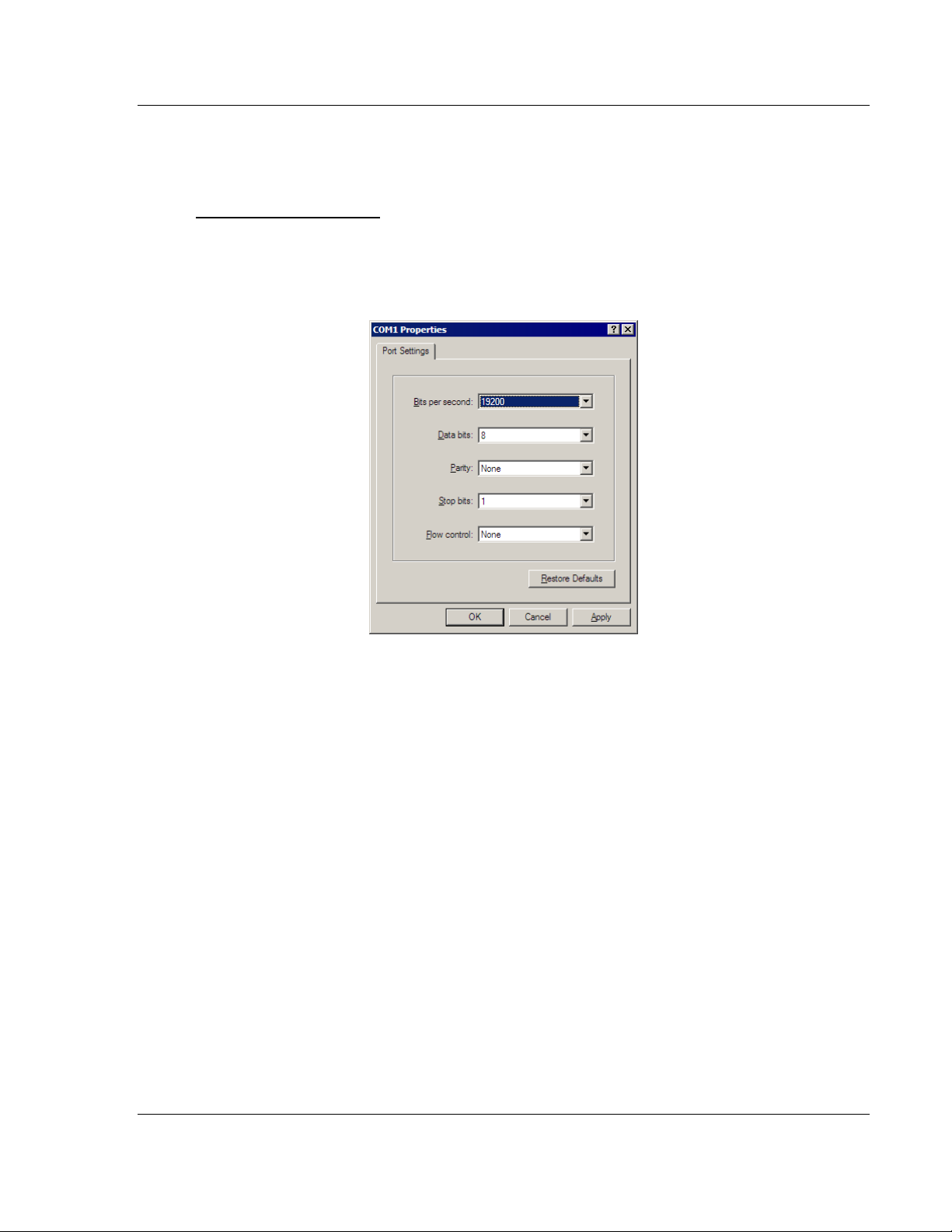
3.6.2 Connecting to the Module
To connect to the module’s Configuration/Debug port:
1 Connect your computer to the module’s port using a null modem cable.
2 Start the communication program on your computer and configure the
communication parameters with the following settings:
3 Open the connection. Send the necessary command to terminate the
module’s program.
If there is no response from the module, follow these steps:
1 Verify that the null modem cable is connected properly between your
computer’s serial port and the module. A regular serial cable will not work.
2 Verify that your communication software is using the correct settings for baud
rate, parity and handshaking.
3 On computers with more than one serial port, verify that your communication
program is connected to the same port that is connected to the module.
4 If you are still not able to establish a connection, you can contact ProSoft
Technology Technical Support for further assistance.
Page 44 of 122 ProSoft Technology, Inc.
February 20, 2013
Page 45
MVI-ADMNET ♦ 'C' Programmable Setting Up Your Development Environment
'C' Programmable Application Development Module with Ethernet Developer's Guide
3.6.3 Enabling the Console
Before you can use RY and SY from the command prompt, you must enable the
console in the ADM module’s BIOS.
To change BIOS settings
1 Remove the module from the rack and install the Setup jumper.
2 Return the module to the rack.
3 Connect to the module using HyperTerminal at 19,200 bps, and then cycle
power to reboot the module.
ProSoft Technology, Inc. Page 45 of 122
February 20, 2013
Page 46

Setting Up Your Development Environment MVI-ADMNET ♦ 'C' Programmable
Developer's Guide 'C' Programmable Application Development Module with Ethernet
4 During the memory check portion of the module’s boot sequence, press
[Ctrl][C] to enter the BIOS configuration menu.
Page 46 of 122 ProSoft Technology, Inc.
February 20, 2013
Page 47

MVI-ADMNET ♦ 'C' Programmable Setting Up Your Development Environment
'C' Programmable Application Development Module with Ethernet Developer's Guide
5 Press [Enter] to enter the MVI-ADMNET module Configuration menu.
6 On the BIOS configuration menu, use the [Tab] key to navigate through the
menu options, and then use the [+] key to toggle the choices.
The options to change are:
o Console on Port 1: change to Enabled
o Console Baud Rate: change to 57600
7 Press [Esc] to return to the Main Menu.
8 Press [Esc] again to apply your changes and reboot the module.
9 Remove the module from the rack and disable the Setup jumper.
To communicate with the module in Console mode
ProSoft Technology, Inc. Page 47 of 122
February 20, 2013
Page 48

Setting Up Your Development Environment MVI-ADMNET ♦ 'C' Programmable
Developer's Guide 'C' Programmable Application Development Module with Ethernet
1 Change the connection settings in HyperTerminal from 19200 to 57600, and
then reconnect to the module.
2 Press [Esc] to exit the program and return to the command prompt.
Important: The autoexec.bat in the image file must allow the application to exit to a DOS prompt.
Page 48 of 122 ProSoft Technology, Inc.
February 20, 2013
Page 49

MVI-ADMNET ♦ 'C' Programmable Setting Up Your Development Environment
'C' Programmable Application Development Module with Ethernet Developer's Guide
3.6.4 Installing RY.exe and SY.exe
To install RY.exe and SY.exe on the module, remove the Compact Flash card
from the module, and then use a Compact Flash card reader on your PC to copy
the files to the root directory of the Compact Flash card. When you reinsert the
Compact Flash card in the module, use the following syntax to send or receive
files.
C:\RY
or
C:\SY "filename.ext"
The filename and path must be in quotes.
Important: You cannot copy files directly to the A:\ drive on the module. To update files on the A
drive, you must create a new ROM image (page 37) and download the image to the module using
MVIFlashUpdate. (page 39) The following procedures show how to send and receive files from the
module’s Compact Flash card (drive C:\).
3.6.5 Downloading Files From a PC to the ADM Module
In order to download files to the module, the ADM module’s running program
must be interrupted. To transfer files to the module, run the RY.EXE program
which uses the YModem protocol.
1 In HyperTerminal, connect to the module at 57600 baud and type the
command to halt the program (for example [Esc] or [Ctrl][C]; your
application must be written to allow itself to exit to the command prompt on
request).
2 At the command prompt, type
C:\RY
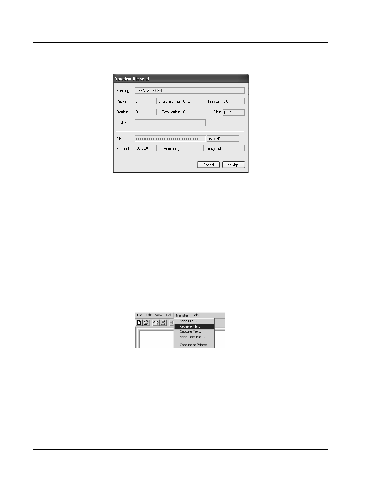
3 In HyperTerminal, open the Transfer menu, and then choose Send File.
4 Click the Browse button to navigate to the folder and file to send to the
module.
5 Chose Ymodem from the Protocol dropdown list, and then click Send.
ProSoft Technology, Inc. Page 49 of 122
February 20, 2013
Page 50
Setting Up Your Development Environment MVI-ADMNET ♦ 'C' Programmable
Developer's Guide 'C' Programmable Application Development Module with Ethernet
6 The Ymodem File Send dialog box shows the file transfer size and remaining
time.
When the file has been transferred to the module, the dialog box will indicate
that the transfer is complete.
3.6.6 Uploading files from the ADM module to a PC
In order to upload files from the module, the ADM module’s running program
must be interrupted. You must run the SY.EXE program which uses the YModem
protocol.
1 In HyperTerminal, connect to the module at 57600 baud and type the
command to halt the program (for example [Esc] or [Ctrl][C]; your
application must be written to allow itself to exit to the command prompt on
request).
2 At the command prompt, type
C:\SY "filename.ext"
The filename and path must be in quotes.
3 From the Transfer menu in HyperTerminal, select Receive File. This action
opens the Receive File dialog box.
4 Use the Browse button to choose a folder on your computer to save the file,
Page 50 of 122 ProSoft Technology, Inc.
February 20, 2013
Page 51

MVI-ADMNET ♦ 'C' Programmable Setting Up Your Development Environment
'C' Programmable Application Development Module with Ethernet Developer's Guide
5 Select Ymodem as the receiving protocol, and then click the Receive button.
When the file has been transferred to your PC, the dialog box will indicate
that the transfer is complete.
ProSoft Technology, Inc. Page 51 of 122
February 20, 2013
Page 52

Setting Up Your Development Environment MVI-ADMNET ♦ 'C' Programmable
Developer's Guide 'C' Programmable Application Development Module with Ethernet
3.7 Installing and Configuring the Module
This chapter describes how to install and configure the module to work with your
application. The configuration process consists of the following steps.
1 Use to identify the module to the processor and add the module to a project.
Note: The software must be in "offline" mode to add the module to a project.
2 Modify the example ladder logic to meet the needs of your application, and
copy the ladder logic to the processor. Example ladder logic files are provided
on the CD-ROM.
Note: If you are installing this module in an existing application, you can copy the necessary
elements from the example ladder logic into your application.
The rest of this chapter describes these steps in more detail.
Note for MVI94: Configuration information for the MVI94-ADM module is stored in the module’s
Flash ROM. This provides permanent storage of the information. The user configures the module
using a text file and then using the terminal emulation software provided with the module to
download it to the module’s Flash ROM. The file contains the configuration for the Flex backplane
data transfer, master port and the command list. This file is downloaded to the module for each
application.
Note for MVI69: Configuration information for the MVI69-ADM module is stored in the module’s
EEPROM. This provides permanent storage of the information. The user configures the module
using a text file and then using the terminal emulation software provided with the module to
download it to the module’s EEPROM. The file contains the configuration for the virtual database,
backplane data transfer, and serial port. This file is downloaded to the module for each application.
3.7.1 Using Side-Connect (Requires Side-Connect Adapter) (MVI71)
If the side-connect interface is used, the file SC_DATA.TXT on the Compact
Flash Disk must contain the correct configuration file number. To set the
configuration file number for your application, run the setdnpsc.exe program.
Install the module in the rack and turn on the power
1 Install the module in the rack and turn on the power.
2 Connect the serial cable to the module’s debug/configuration port
3 To exit the program, [ESC], followed by [Y]. The program will exit and remain
at the operating system prompt.
4 Run the setdnpsc.exe program with a command line argument of the file
number to use for the configuration file. For example, to select N10: as the
configuration file, enter the following:
SETDNPSC 10
The program will build the SC_DATA.TXT on the Compact Flash Disk (C: drive in
the root directory).
Page 52 of 122 ProSoft Technology, Inc.
February 20, 2013
Page 53

MVI-ADMNET ♦ 'C' Programmable Setting Up Your Development Environment
File Number
Example
Size
Description
Cfg File
N10
300
Configuration/Control/Status File
Cfg File+1
N11
to 1000
Port 1 commands 0 to 99
Cfg File+2
N12
to 1000
Port 2 commands 0 to 99
Cfg File+5
N15
to 1000
Data transferred from the module to the processor.
Other files for read data.
Cfg File+5+n
N16
to 1000
Data transferred from the processor to the module.
Cfg File +5+n+m
Other files for write data.
Data Files
Description
N15:0 to 239
Read Data
N16:0 to 239
Write Data
Data Files
Description
N15:0 to 999
Read data words 0 to 999
N16:0 to 999
Read data words 1000 to 1999
N17:0 to 299
Read data words 2000 to 2299
N18:0 to 999
Write data words 0 to 999
N19:0 to 999
Write data words 1000 to 1999
N20:0 to 999
Write data words 2000 to 2999
N21:0 to 499
Write data words 3000 to 3499
'C' Programmable Application Development Module with Ethernet Developer's Guide
Next, define the data files for the application. If the block transfer interface is
used, define the data files to hold the configuration, status, and user data. Enter
the module’s configuration in the user data files. Enter the ladder logic to handle
the blocks transferred between the module and the PLC. Download the program
to the PLC and test the program with the module.
If the side-connect interface is used, no ladder logic is required for data transfer.
The user data files to interface with the module must reside in contiguous order
in the processor. The first file to be used by the interface is the configuration file.
This is the file number set in the SC_DATA.TXT file using the SETDNPSC.EXE
program. The following table lists the files used by the side-connect interface:
n is the number of read data files minus one. Each file contains up to 1000
words.
m is the number of write data files minus one. Each file contains up to 1000
words.
Even if both files are not required for a port’s commands, they are still reserved
and should only be used for that purpose. The read and write data contained in
the last set of files possess the data transferred between the module and the
processor. The number of files required for each depends on the number of
registers configured for each operation. Two examples follow:
Example of 240 words of read and write data (cfg file=10)
Example of 2300 read and 3500 write data registers (cfg file=10)
ProSoft Technology, Inc. Page 53 of 122
February 20, 2013
Page 54

Setting Up Your Development Environment MVI-ADMNET ♦ 'C' Programmable
Developer's Guide 'C' Programmable Application Development Module with Ethernet
Special care must be taken when defining the files for the side-connect interface.
Because the module directly interacts with the PLC processor and its memory,
any errors in the configuration may cause the processor to fault and it may even
lose its configuration program. After defining the files and populating them with
the correct data, download the program to the processor, and place the
processor in Run mode. If everything is configured properly, the module should
start its normal operation.
If all the configuration parameters are set correctly, the module’s application LED
(OK LED) should remain off and the backplane activity LED (BP ACT) should
blink rapidly. Refer to the Diagnostics and Troubleshooting of this manual if you
encounter errors. Attach a terminal to Port 1 on the module and look at the status
of the module using the Configuration/Debug Menu in the module.
Page 54 of 122 ProSoft Technology, Inc.
February 20, 2013
Page 55

MVI-ADMNET ♦ 'C' Programmable Understanding the MVI-ADMNET API
In This Chapter
API Libraries .......................................................................................... 56
Development Tools ............................................................................... 58
Theory of Operation .............................................................................. 59
ADM API Files ....................................................................................... 60
'C' Programmable Application Development Module with Ethernet Developer's Guide
4 Understanding the MVI-ADMNET API
The MVI ADM API Suite allows software developers access to the top layer of
the serial and Ethernet ports. The MVI-ADMNET API suite accesses the Ethernet
port. Both APIs can be easily used without having detailed knowledge of the
module’s hardware design. The MVI ADMNET API Suite consists of the Ethernet
Port API. The Ethernet Port API provides access to the Ethernet network.
Applications for the MVI ADMNET module may be developed using industry-
standard DOS programming tools and the appropriate API components.
This section provides general information pertaining to application development
for the MVI ADMNET module.
ProSoft Technology, Inc. Page 55 of 122
February 20, 2013
Page 56

Understanding the MVI-ADMNET API MVI-ADMNET ♦ 'C' Programmable
Developer's Guide 'C' Programmable Application Development Module with Ethernet
4.1 API Libraries
Each API provides a library of function calls. The library supports any
programming language that is compatible with the Pascal calling convention.
Each API library is a static object code library that must be linked with the
application to create the executable program. It is distributed as a 16-bit large
model OMF library, compatible with Digital Mars C++ or Borland development
tools.
Note: The following compiler versions are intended to be compatible with the MVI module API:
Digital Mars C++ 8.49
Borland C++ V5.02
More compilers will be added to the list as the API is tested for compatibility with them.
4.1.1 Calling Convention
The API library functions are specified using the 'C' programming language
syntax. To allow applications to be developed in other industry-standard
programming languages, the standard Pascal calling convention is used for all
application interface functions.
4.1.2 Header File
A header file is provided along with each library. This header file contains API
function declarations, data structure definitions, and miscellaneous constant
definitions. The header file is in standard 'C' format.
4.1.3 Sample Code
A sample application is provided to illustrate the usage of the API functions. Full
source for the sample application is also provided. The sample application may
be compiled using Digital Mars or Borland C++.
Important: The sample code and libraries in the 1756-MVI-Samples folder are not compatible with,
and are not supported for, the Digital Mars compiler.
Page 56 of 122 ProSoft Technology, Inc.
February 20, 2013
Page 57

MVI-ADMNET ♦ 'C' Programmable Understanding the MVI-ADMNET API
'C' Programmable Application Development Module with Ethernet Developer's Guide
4.1.4 Multi-threading Considerations
The DOS 6-XL operating system supports the development of multi-threaded
applications.
Note: The multi-threading library kernel.lib in the DOS folder on the distribution CD-ROM is
compiler-specific to Borland C++ 5.02. It is not compatible with Digital Mars C++ 8.49. ProSoft
Technology, Inc. does not support multi-threading with Digital Mars C++ 8.49.
Note: The ADM DOS 6-XL operating system has a system tick of 5 milliseconds. Therefore, thread
scheduling and timer servicing occur at 5ms intervals. Refer to the DOS 6-XL Developer’s Guide
on the distribution CD-ROM for more information.
Multi-threading is also supported by the API.
DOS and cipapi libraries have been tested and are thread-safe for use in
multi-threaded applications.
MVIbp and MVIsp libraries are safe to use in multi-threaded applications with
the following precautions: If you call the same MVIbp or MVIsp function from
multiple threads, you will need to protect it, to prevent task switches during
the function's execution. The same is true for different MVIbp or MVIsp
functions that share the same resources (for example, two different functions
that access the same read or write buffer).
WARNING: ADM and ADMNET libraries are not thread-safe. ProSoft Technology, Inc. does not
support the use of ADM and ADMNET libraries in multi-threaded applications.
ProSoft Technology, Inc. Page 57 of 122
February 20, 2013
Page 58

Understanding the MVI-ADMNET API MVI-ADMNET ♦ 'C' Programmable
Developer's Guide 'C' Programmable Application Development Module with Ethernet
4.2 Development Tools
An application developed for the MVI ADM module must be stored on the
module’s Flash ROM disk in order to be executed.
Page 58 of 122 ProSoft Technology, Inc.
February 20, 2013
Page 59
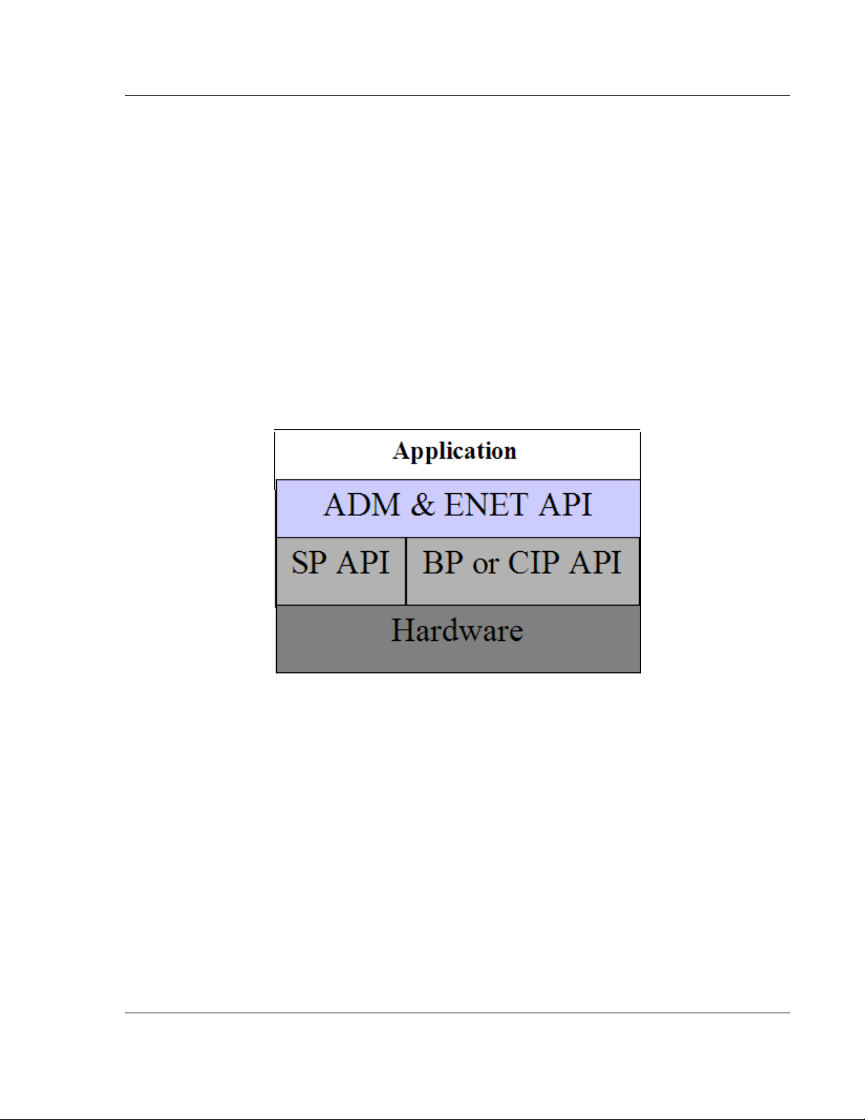
MVI-ADMNET ♦ 'C' Programmable Understanding the MVI-ADMNET API
'C' Programmable Application Development Module with Ethernet Developer's Guide
4.3 Theory of Operation
4.3.1 ADM API
The ADMNET API is one component of the MVI ADM API Suite. The ADMNET
API provides a simple module-level interface that is portable between members
of the MVI Family. This is useful when developing an application that implements
a serial-Ethernet protocol for a particular device, such as a scale or bar code
reader. After an application has been developed, it can be used on any of the
MVI family modules.
4.3.2 ADMNET API Architecture
The ADMNET API is composed of a statically-linked library (called the ADMNET
library). Applications using the ADMNET API must be linked with the ADMNET
library.
The following illustration shows the relationship between the API components.
ProSoft Technology, Inc. Page 59 of 122
February 20, 2013
Page 60

Understanding the MVI-ADMNET API MVI-ADMNET ♦ 'C' Programmable
File Name
Description
ADMNETAPI.H
Include file
ADMNETAPI.LIB
Library (16-bit OMF format)
Developer's Guide 'C' Programmable Application Development Module with Ethernet
4.4 ADM API Files
The following table lists the supplied API file names. These files should be copied
to a convenient directory on the computer where the application is to be
developed. These files need not be present on the module when executing the
application.
4.4.1 ADM Interface Structure
The ADMNET interface structure functions mainly as a protocol UDP and TCP
socket. Pointers to structures are used so that the API can access lower-level
Ethernet communication. The ADMNET API requires the interface structure and
the structures referenced by it. Refer to the example code section for examples
of the functions.
The interface structure is as follows:
typedef struct _tcp_socket {
struct _tcp_socket *next;
word ip_type; // always set to TCP_PROTO
char *err_msg;
char *usr_name;
void (*usr_yield)(void);
byte rigid;
byte stress;
word sock_mode; // a logical OR of bits
longword usertimer; // ip_timer_set, ip_timer_timeout
dataHandler_t dataHandler; // called with incoming data
eth_address hisethaddr; // ethernet address of peer
longword hisaddr; // internet address of peer
word hisport; // tcp ports for this connection
longword myaddr;
word myport;
word locflags;
int queuelen;
byte *queue;
int rdatalen; // must be signed
word maxrdatalen;
byte *rdata;
byte rddata[tcp_MaxBufSize+1]; // received data
longword safetysig;
word state; // connection state
longword acknum;
longword seqnum; // data ack'd and sequence num
long timeout; // timeout, in milliseconds
byte unhappy; // flag, indicates retransmitting
segt's
byte recent; // 1 if recently transmitted
Page 60 of 122 ProSoft Technology, Inc.
February 20, 2013
Page 61

MVI-ADMNET ♦ 'C' Programmable Understanding the MVI-ADMNET API
'C' Programmable Application Development Module with Ethernet Developer's Guide
word flags; // tcp flags word for last packet
sent
word window; // other guy's window
int datalen; // number of bytes of data to send
// must be signed
int unacked; // unacked data
byte cwindow; // Van Jacobson's algorithm
byte wwindow;
word vj_sa; // VJ's alg, standard average
word vj_sd; // VJ's alg, standard deviation
longword vj_last; // last transmit time
word rto;
byte karn_count; // count of packets
byte tos; // priority
// retransmission timeout
procedure
// these are in clock ticks
longword rtt_lasttran; // last transmission time
longword rtt_smooth; // smoothed round trip time
longword rtt_delay; // delay for next transmission
longword rtt_time; // time of next transmission
word mss;
longword inactive_to; // for the inactive flag
int sock_delay;
byte data[tcp_MaxBufSize+1]; // data to send
} tcp_Socket;
typedef struct _udp_socket {
struct _udp_socket *next;
word ip_type; // always set to UDP_PROTO
char *err_msg; // null when all is ok
char *usr_name;
void (*usr_yield)( void );
byte rigid;
byte stress;
word sock_mode; // a logical OR of bits
longword usertimer; // ip_timer_set, ip_timer_timeout
dataHandler_t dataHandler;
eth_address hisethaddr; // peer's ethernet address
longword hisaddr; // peer's internet address
word hisport; // peer's UDP port
longword myaddr;
word myport;
word locflags;
int queuelen;
byte *queue;
int rdatalen; // must be signed
word maxrdatalen;
byte *rdata;
ProSoft Technology, Inc. Page 61 of 122
February 20, 2013
Page 62

Understanding the MVI-ADMNET API MVI-ADMNET ♦ 'C' Programmable
Developer's Guide 'C' Programmable Application Development Module with Ethernet
byte rddata[ tcp_MaxBufSize + 1]; // if dataHandler = 0, len ==
512
longword safetysig;
} udp_Socket;
Page 62 of 122 ProSoft Technology, Inc.
February 20, 2013
Page 63

MVI-ADMNET ♦ 'C' Programmable Application Development Function Library - ADMNET API
In This Chapter
ADMNET API Functions ........................................................................ 64
ADMNET API Initialize Functions .......................................................... 65
ADMNET API Release Socket Functions .............................................. 68
ADMNET API Send Socket Functions ................................................... 70
ADMNET API Receive Socket Functions .............................................. 72
ADMNET API Miscellaneous Functions ................................................ 74
'C' Programmable Application Development Module with Ethernet Developer's Guide
5 Application Development Function Library -
ADMNET API
ProSoft Technology, Inc. Page 63 of 122
February 20, 2013
Page 64

Application Development Function Library - ADMNET API MVI-ADMNET ♦ 'C' Programmable
Function Category
Function Name
Description
Initialize Socket
ADM_init_socket
Initialize number of sockets used on
each port number and assign name to
each port.
ADM_open_sk
Open and reopen each socket
separately after socket is initialized or
closed.
ADM_init_UDP_buffer
Attaches a user supplied buffer to the
UDP socket for storing the received
messages. Since the buffer is user
supplied, the user can adjust the size
to suit the application.
Release Socket
ADM_release_sockets
Release all sockets that have been
initialized using ADM_init_socket.
ADM_close_sk
Close each socket separately without
release socket.
Send Socket
ADM_send_socket
Send socket according to name assign
throughout initialization process as
either UDP or TCP. This function also
takes care of opening socket
connection.
ADM_send_sk
Send socket with previously open with
function ADM_open_sk.
Receive Socket
ADM_receive_socket
Receive socket according to name
assigned throughout initialization
process as either UDP or TCP. This
function also takes care of opening
socket connection.
ADM_receive_sk
Receive socket with previously open
with function ADM_open_sk.
ADM_receive_buffered_UDP_s
k
This function is used to receive
messages when ADM_init_UDP_buffer
is used. Received messages will be
placed in the buffer pointed to by
holdRecPtr. The parameter readLen
will be updated with the length of the
received message. The client’s IP
address will be placed in fromIP.
Miscellaneous
ADM_NET_GetVersionInfo
Get ADMNET API version information.
ADM_is_sk_open
Test if the socket is still open.
Developer's Guide 'C' Programmable Application Development Module with Ethernet
5.1 ADMNET API Functions
This section provides detailed programming information for each of the ADMNET
API library functions. The calling convention for each API function is shown in 'C'
format.
The same set of API functions is supported for all of the modules in the MVI
family.
API library routines are categorized according to functionality.
Page 64 of 122 ProSoft Technology, Inc.
February 20, 2013
Page 65

MVI-ADMNET ♦ 'C' Programmable Application Development Function Library - ADMNET API
numSK
Variable indicating how many sockets to use.
portNum
Port Number.
buffSize
The size of the buffer available in each socket.
name
The name of the socket.
SK_SUCCESS
API has successfully initialized variables.
SK_PORT_NOT_ALLOW
API does not allow port number used.
SK_CANNOT_ALLOCATE_MEMORY
API cannot allocate memory.
'C' Programmable Application Development Module with Ethernet Developer's Guide
5.2 ADMNET API Initialize Functions
The following topics describe the ADMNET API Initialize functions.
ADM_init_socket
Syntax
int ADM_init_socket(int numSK, int portNum, int buffSize, char *name);
Parameters
Description
ADM_init_socket acquires access to the ADMNET API and dynamically
generates a set of sockets according to numSK and assigns portNum, buffSize,
then names each socket that the application will use in subsequent functions.
This function must be called before any of the other API functions can be used.
IMPORTANT After the API has been opened, ADM_Release_Sockets should always be called
before exiting the application.
Return Value
Example
int numSK = 5;
int portNum = 5757;
int buffSize = 1000;
if(ADM_init_socket(numSK, portNum, buffSize, "ReceiveSK") != SK_SUCCESS)
{
printf("\nFailed to open ADM API... exiting program\n");
ADM_release_sockets();
}
See Also
ADM_release_sockets (page 68)
ProSoft Technology, Inc. Page 65 of 122
February 20, 2013
Page 66

Application Development Function Library - ADMNET API MVI-ADMNET ♦ 'C' Programmable
skName
Name of the socket that has been initialized and used to send data.
ServerIPAddress
IP address that will be used to send data to.
protocol
Specified protocol to send over Ethernet (USE_TCP or USE_UDP).
SK_SUCCESS
API has successfully opened socket.
SK_PROCESS_SOCKET
Open is still in process.
SK_NOT_FOUND
API could not find an initialized socket with the name passed to the
function.
SK_TIMEOUT
Time out opening socket.
SK_OPEN_FAIL
Socket could not be opened.
Developer's Guide 'C' Programmable Application Development Module with Ethernet
ADM_open_sk
Syntax
int ADM_open_sk(char *skName, char *ServerIPAddress, int protocol);
Parameters
Description
ADM_open_sk opens a socket according to the name previously initialized,
skName, with ADM_init_socket given, and assigns IP address, ServerIPAddress
for send function with specific protocol, either UDP or TCP. ADM_init_socket
must be used before this function. Returns SK_TIMEOUT if no connection is
made within 30 seconds.
IMPORTANT: After the API has been opened, ADM_close_sk should always be called for closing
the socket. 0.0.0.0 passes as ServerIPAddress to open socket as a server to listen to a message
from client.
Return Value
Example
char sockName1[ ] = "SendSocket";
int buffSize1 = 4096;
int port_1 = 6565;
int numSocket1 = 1;
int result;
sock_init(); //initialize the socket interface
ADM_init_socket(numSocket1, port_1, buffSize1, sockName1);
while ((result = ADM_open_sk(sockName1, "0.0.0.0",
USE_TCP))==SK_PROCESS_SOCKET);
if (result==SK_SUCCESS)
{
printf("successfully Opened a connection!\n");
} else {
printf("Error Opening a connection! %d\n", result);
}
Page 66 of 122 ProSoft Technology, Inc.
February 20, 2013
Page 67

MVI-ADMNET ♦ 'C' Programmable Application Development Function Library - ADMNET API
Parameters
skName
Name of the socket that has been initialized and used to receive data
buffer
Pointer to a buffer to hold received messages
maxlength
Maximum length of each message in the buffer
Return Value
SK_SUCCESS
Buffer has been attached to UDP socket
successfully.
SK_NOT_FOUND
Socket could not be found.
SK_CANNOT_ALLOCATE_MEMORY
API cannot allocate memory.
'C' Programmable Application Development Module with Ethernet Developer's Guide
ADM_init_UDP_buffer
Syntax
int ADM_init_UDP_buffer(char *skName, char **buffer, int maxLength);
Description
ADM_init_UDP_buffer attaches a user supplied buffer to the UDP socket for
storing the received messages. Since the buffer is user supplied, the user can
adjust the size to suit the application.
Example
char sockName1[] = "ReceiveSocket";
#define BIG_BUFFER_SIZE_CYCLIC 32767 /* each rx buff is 1500 bytes of
data and 12 bytes header for buffer = 12 buffers */
char far bigbuff0[BIG_BUFFER_SIZE_CYCLIC]; //buffer to store received
UDP datagrams
if(ADM_init_UDP_buffer(sockName1, (char**)&bigbuff0[0],
BIG_BUFFER_SIZE_CYCLIC))
{
printf("\nCould not enable large buffers for server!\n");
sock_close(sockName1);
return;
}
printf("listen for datagrams\n");
ProSoft Technology, Inc. Page 67 of 122
February 20, 2013
Page 68

Application Development Function Library - ADMNET API MVI-ADMNET ♦ 'C' Programmable
SK_SUCCESS
API was successfully released all the sockets.
Developer's Guide 'C' Programmable Application Development Module with Ethernet
5.3 ADMNET API Release Socket Functions
This section describes the ADMNET API Release Socket Functions.
ADM_release_sockets
Syntax
int ADM_release_sockets(void);
Parameters
none
Description
This function is used by an application to release all sockets created by
ADM_init_socket.
IMPORTANT: After a socket has been generated, this function should always be called before
exiting the application.
Return Value
Example
ADM_release_sockets();
See Also
ADM_init_socket (page 65)
Page 68 of 122 ProSoft Technology, Inc.
February 20, 2013
Page 69

MVI-ADMNET ♦ 'C' Programmable Application Development Function Library - ADMNET API
skName
Name of the socket that has been initialized and used
to send data.
SK_SUCCESS
API was successfully released all the sockets.
SK_NOT_FOUND
API could not find an initialized socket with the name
passed to the function.
'C' Programmable Application Development Module with Ethernet Developer's Guide
ADM_close_sk
Syntax
int ADM_close_sk(char *skName);
Parameters
Description
This function is used by an application to close socket opened by ADM_open_sk.
IMPORTANT: After a socket has been opened, this function should always be called to close
socket, but not release socket.
Return Value
Example
char sockName1[ ] = "SendSocket";
ADM_close_sk(sockName1);
printf ("Connection Closed!\n");
See Also
ADM_init_socket (page 65)
ProSoft Technology, Inc. Page 69 of 122
February 20, 2013
Page 70

Application Development Function Library - ADMNET API MVI-ADMNET ♦ 'C' Programmable
skName
Name of the socket that has been initialized and used to
send data.
holdSendPtr
Pointer to a string of data that will be sent to the
ServerIPAddress
sendLen
Number of data specified to send.
ServerIPAddress
IP address that will be used to send data to.
protocol
Specified protocol to send over Ethernet (USE_TCP or
USE_UDP).
SK_SUCCESS
Socket is successfully sent.
SK_NOT_FOUND
Socket could not be found.
SK_PROCESS_SOCKET
Socket is in the process of sending.
Developer's Guide 'C' Programmable Application Development Module with Ethernet
5.4 ADMNET API Send Socket Functions
This section describes the ADMNET API Send Socket functions.
ADM_send_socket
Syntax
int ADM_send_socket(char *skName, char *holdSendPtr, int *sendLen, char
*ServerIPAddress, int protocol);
Parameters
Description
To simplify a program, this function opens connection and sends message.
skName must be a valid name that has been initialized with ADM_init_socket.
Return Value
Example
int sendLen = 10;
int se;
se = ADM_send_socket("sendSK", "1234567890", &sendLen, "192.168.0.148",
USE_UDP);
if(se == SK_SUCCESS)
{
printf("send Success\n");
}
See Also
ADM_receive_socket (page 72)
Page 70 of 122 ProSoft Technology, Inc.
February 20, 2013
Page 71

MVI-ADMNET ♦ 'C' Programmable Application Development Function Library - ADMNET API
skName
Name of the socket that has been initialized and used
to send data.
holdSendPtr
Pointer to a string of data that will be sent to the
ServerIPAddress
sendLen
Number of data specified to send.
SK_SUCCESS
API has successfully open socket.
SK_PROCESS_SOCKET
Open process is still in
SK_NOT_FOUND
API could not find an initialized socket with the name
passed to the function.
'C' Programmable Application Development Module with Ethernet Developer's Guide
ADM_send_sk
Syntax
int ADM_send_sk(char *skName, char *holdSendPtr, int *sendLen);
Parameters
Description
ADM_ send _sk sends with a socket previously open using ADM_open_sk.
Return Value
Example
char sockName1[ ] = "SendSocket";
char holdingReg[100];
int buffSize1 = 4096;
int port_1 = 6565;
int numSocket1 = 1;
int result;
sock_init(); //initialize the socket interface
ADM_init_socket(numSocket1, port_1, buffSize1, sockName1);
sprintf(holdingReg,"abcdefghijklmnopqrstuvwxyz-");
sendLen = 27;
while ((result = ADM_send_sk(sockName1, holdingReg, &sendLen)) ==
SK_PROCESS_SOCKET);
if(result == SK_SUCCESS)
{
printf("Data: %s Sent \n", holdingReg);
} else {
printf("Error sending data\n");
}
See Also
ADM_receive_sk (page 73)
ProSoft Technology, Inc. Page 71 of 122
February 20, 2013
Page 72

Application Development Function Library - ADMNET API MVI-ADMNET ♦ 'C' Programmable
skName
Name of the socket that has been initialized and used to receive data.
holdRecPtr
Pointer to a buffer to hold data that will be received by the API.
readLen
Length of data received by the API.
protocol
Specified protocol to receive over Ethernet (USE_TCP or USE_UDP).
SK_SUCCESS
Socket is successfully sent.
SK_NOT_FOUND
Socket could not be found.
SK_PROCESS_SOCKET
Socket is in the process of sending.
Developer's Guide 'C' Programmable Application Development Module with Ethernet
5.5 ADMNET API Receive Socket Functions
This section describes the ADMNET API Receive Socket functions.
ADM_receive_socket
Syntax
int ADM_receive_socket(char *skName, char *holdRecPtr, int *readLen, int
protocol);
Parameters
Description
To simplify a program, this function opens connection and receives message.
Return Value
Example
char hold[5000];
int readLen;
int se, i;
se = ADM _receive_socket("receiveSK", holdingReg, &readLen, USE_UDP);
if(se == SK_SUCCESS)
{
printf("Length == %d\n", readLen);
for (i=0; i<readLen; i++)
{
printf("%02X ", *(holdingReg+i));
if(i%10 == 0) printf("\n");
}
printf("\n");
}
See Also
ADM_send_socket (page 70)
Page 72 of 122 ProSoft Technology, Inc.
February 20, 2013
Page 73

MVI-ADMNET ♦ 'C' Programmable Application Development Function Library - ADMNET API
skName
Name of the socket that has been initialized and used to receive data.
holdRecPtr
Pointer to a buffer to hold data that will be received by the API.
readLen
Length of data received by the API.
fromIP
Pointer to character array which in turn return with client IP.
SK_SUCCESS
Socket is successfully sent.
SK_NOT_FOUND
Socket could not be found.
SK_PROCESS_SOCKET
Socket is in the process of sending.
SK_TIMEOUT
Time out opening socket.
'C' Programmable Application Development Module with Ethernet Developer's Guide
ADM_receive_sk
Syntax
int ADM_receive_sk(char *skName, char *holdRecPtr, int *readLen, char *fromIP);
Parameters
Description
This function receives socket after ADM_open_sk is used. skName must be a
valid name that has been initialized with ADM_init_socket.
Return Value
Example
char sockName1[ ] = "SendSocket";
char holdingReg[100];
int result;
while ((result=ADM_receive_sk(sockName1, holdingReg, &readLen, fromIP)) ==
SK_PROCESS_SOCKET);
if(result == SK_SUCCESS){
printf("Received data!\n");
printf("Length == %d\n", readLen);
for (i=0; i<readLen; i++)
{
printf("%c", *(holdingReg+i));
}
printf("\n");
} else {
printf("Received no data Error: %d\n",result);
}
ProSoft Technology, Inc. Page 73 of 122
February 20, 2013
Page 74

Application Development Function Library - ADMNET API MVI-ADMNET ♦ 'C' Programmable
Parameters
skName
Name of the socket that has been initialized and used to receive messages
holdRecPtr
Pointer to a buffer to hold data that will be received by the API
readLen
Length of data received by the API
fromIP
Character array to hold client IP address
nBlock
Function will block on receive if nBlock > 0. If nBlock is 0, the function will
return
Return Value
SK_SUCCESS
Message received if nBlock is non-zero. If nBlock is 0 then this
denotes a successful receive check which will result in a received
message if a message was available..
SK_NOT_FOUND
Socket could not be found.
SK_SOCKET_CLOSE
Socket is closed
Developer's Guide 'C' Programmable Application Development Module with Ethernet
ADM_receive_buffered_UDP_sk
Syntax
int ADM_receive_buffered_UDP_sk(char *skName, char *holdRecPtr, int
*readLen, char *fromIP, int nBlock);
Description
This function is used to receive messages when ADM_init_UDP_buffer is used.
Received messages will be placed in the buffer pointed to by holdRecPtr. The
parameter readLen will be updated with the length of the received message. The
client’s IP address will be placed in fromIP.
Example
char sockName1[] = "ReceiveSocket";
char data[1024];
int length;
char fromIP[64];
unsigned long recvVal[10];
length = MAX_MESSAGE;
err = ADM_receive_buffered_UDP_sk(sockName1, data, &length, fromIP, 1);
if(length > 0)
{
recvVal[index++] = *(unsigned long *)data;
}
if(err < 0)
{
printf("got error\n");
}
Page 74 of 122 ProSoft Technology, Inc.
February 20, 2013
Page 75

MVI-ADMNET ♦ 'C' Programmable Application Development Function Library - ADMNET API
admnet_verinfo
Pointer to structure of type ADMNETVERSIONINFO.
'C' Programmable Application Development Module with Ethernet Developer's Guide
5.6 ADMNET API Miscellaneous Functions
ADM_NET_GetVersionInfo
Syntax
void ADM_NET_GetVersionInfo(ADMNETVERSIONINFO* admnet_verinfo);
Parameters
Description
ADM_GetVersionInfo retrieves the current version of the ADMNET API library.
The information is returned in the structure admnet_verinfo.
The ADMVERSIONINFO structure is defined as follows:
typedef struct
{
char APISeries[4];
short APIRevisionMajor;
short APIRevisionMinor;
long APIRun;
}ADMNETVERSIONINFO;
Return Value
None
Example
ADMNETVERSIONINFO verinfo;
/* print version of API library */
ADM_NET_GetVersionInfo(& verinfo);
printf("Revision %d.%d\n", verinfo.APIRevisionMajor, verinfo.APIRevisionMinor);
ProSoft Technology, Inc. Page 75 of 122
February 20, 2013
Page 76

Application Development Function Library - ADMNET API MVI-ADMNET ♦ 'C' Programmable
skName
Name of the socket that has been initialized and used to receive data.
SK_SUCCESS
Socket is successfully sent.
SK_NOT_FOUND
Socket could not be found.
SK_SOCKET_CLOSE
Socket is closed.
Developer's Guide 'C' Programmable Application Development Module with Ethernet
ADM_is_sk_open
Syntax
int ADM_is_sk_open(char *skName);
Parameters
Description
ADM_is_sk_open tests if connection is still valid or not.
Return Value
Example
char sockName1[ ] = "SendSocket";
if(ADM_is_sk_open(sockName1) != SK_SUCCESS) {
printf("Socket not Opened\n");
} else {
printf("Socket Opened\n");
}
Page 76 of 122 ProSoft Technology, Inc.
February 20, 2013
Page 77

MVI-ADMNET ♦ 'C' Programmable WATTCP API Functions
In This Chapter
WATTCP API Functions ........................................................................ 78
ADMNET API Initialize Functions .......................................................... 80
ADMNET API System Functionality ...................................................... 81
ADMNET API Release Socket Functions .............................................. 96
ADMNET API Send Socket Functions ................................................... 99
ADMNET API Receive Socket Functions ............................................ 105
'C' Programmable Application Development Module with Ethernet Developer's Guide
6 WATTCP API Functions
ProSoft Technology, Inc. Page 77 of 122
February 20, 2013
Page 78

WATTCP API Functions MVI-ADMNET ♦ 'C' Programmable
Function Category
Function Name
Description
Initialize Socket
sock_init
TCP/IP system initialization.
System Functionality
tcp_tick
Determine socket connection.
tcp_open &
tcp_open_fast
Generate socket session to a host
computer for TCP protocol.
tcp_open_fast will have no wait for if the
host computer is not found.
udp_open &
udp_open_fast
Generate socket session to a host
computer for UDP protocol.
udp_open_fast will have no wait for if the
host computer is not found.
resolve
Convert string IP Address into a
longword.
sock_mode
Setup socket protocol transfer mode for
the particular use (UDP or TCP).
sock_established
Check if connect has been established.
ip_timer_init
Initialize timing.
ip_timer_expired
Check if timer has been expired.
set_timeout
Set timer.
chk_timeout
Check timer if expired.
sockerr
Return ASCII error message if there is
any.
sockstate
Return ASCII message what is the
current state.
gethostid
Returned value is the IP address in host
format.
Release Socket
sock_exit
Release all the TCP/IP system initialized
by sock_init.
sock_abort
Abort a connection.
sock_close
Close a connection.
Send Socket
sock_write &
sock_fastwrite
Write data out to a port. sock_fastwrite
will have no check for data written out to
the socket.
sock_flush
Flush data out to the socket to make
sure all the data has been sent.
sock_flushnext
Call before write the data out to make
sure that after write the data out to the
socket, buffer will be flushed.
sock_puts
Put string onto the buffer.
sock_putc
Put a character onto the buffer.
Developer's Guide 'C' Programmable Application Development Module with Ethernet
6.1 WATTCP API Functions
This API is a TCP/IP stack, which is used on ADMNET API. Parts of this
document are brought from Waterloo TCP by Erik Engelke. Each section
provides detailed programming information for each WATTCP API library
function. The calling convention for each API function is shown in 'C' format.
The API library routines are categorized according to functionality as shown in
the following table.
Page 78 of 122 ProSoft Technology, Inc.
February 20, 2013
Page 79

MVI-ADMNET ♦ 'C' Programmable WATTCP API Functions
Function Category
Function Name
Description
Receive Socket
sock_read & sock_fastread
Read data coming into a port.
tcp_listen
Listen to a message coming in to a
specified port.
sock_gets
Get String
sock_getc
Get Character
sock_dataready
Return the number data ready to be
read.
rip
Remove carriage returns and line feeds.
Miscellaneous
inet_ntoa
Build ASCII representation of an IP
address with a user supply string from
decimal representation of the IP
address.
inet_addr
Convert string dot address to host
format.
ntohs
Convert network word to host word
htons
Convert host word to network word
ntohl
Convert network longword to host
longword
htonl
Convert host longword to network
longword
'C' Programmable Application Development Module with Ethernet Developer's Guide
ProSoft Technology, Inc. Page 79 of 122
February 20, 2013
Page 80

WATTCP API Functions MVI-ADMNET ♦ 'C' Programmable
SK_SUCCESS
API has successfully initialized variables.
SK_PORT_NOT_ALLOW
API does not allow port number used.
SK_CANNOT_ALLOCATE_MEMORY
API cannot allocate memory.
Developer's Guide 'C' Programmable Application Development Module with Ethernet
6.2 ADMNET API Initialize Functions
The following topics detail the ADMNET API Initialize functions.
sock_init
Syntax
void sock_init(void);
Parameters
None
Description
This function will read a stored TCP/IP configuration file and prepare a variable.
Return Value
Example
int numSK = 5;
int portNum = 5757;
int buffSize = 1000;
sock_init(); //initialize the socket interface
/* initialize each socket */
if(ADM_init_socket(numSK, portNum, buffSize, "ReceiveSK") != SK_SUCCESS)
{
printf("\nFailed to open ADM API... exiting program\n");
ADM_release_sockets();
}
See Also
sock_exit (page 96)
Page 80 of 122 ProSoft Technology, Inc.
February 20, 2013
Page 81

MVI-ADMNET ♦ 'C' Programmable WATTCP API Functions
skType
Current socket Type or NULL for all sockets.
0
disconnected or reset.
>0
connected.
'C' Programmable Application Development Module with Ethernet Developer's Guide
6.3 ADMNET API System Functionality
The following topics describe the ADMNET API System Functionality calls.
tcp_tick
Syntax
int tcp_tick( sock_type *skType );
Parameters
Description
This function is used by an application to determine the connection status of the
sockets.
Return Value
Example
sock_type *socket;
. . .
if(tcp_tick(socket)) //check socket
{
printf("Connected\n");
}
ProSoft Technology, Inc. Page 81 of 122
February 20, 2013
Page 82

WATTCP API Functions MVI-ADMNET ♦ 'C' Programmable
sk
Pointer to the socket that has been initialized.
lPort
Local port number.
ina
Host IP Address.
port
Host port number.
datahandler
Data Handler. Not used in this version. Use NULL for this parameter.
Connection cannot be made
>0
Connection is made
Developer's Guide 'C' Programmable Application Development Module with Ethernet
tcp_open
Syntax
int tcp_open( tcp_Socket *sk, word lPort, longword ina, word port,
dataHandler_t datahandler );
Parameters
Description
This function opens a TCP socket connection to a host machine using
parameters passed to it. IPort is an option parameter. Most of the time, IPort can
be set to 0. The API will find an available port number for the socket. ina is a host
IP address passed as a longword. Function resolve can be used to convert an IP
address into longword-formatted variable.
Return Value
Example
tcp_Socket *socket;
. . .
if(tcp_open(socket, 0, resolve("192.168.0.1"), 5656, NULL))
{
printf("Open Successfully\n");
}
See Also
resolve (page 86)
Page 82 of 122 ProSoft Technology, Inc.
February 20, 2013
Page 83

MVI-ADMNET ♦ 'C' Programmable WATTCP API Functions
sk
Pointer to the socket that has been initialized.
lPort
Local port number.
ina
Host IP Address.
port
Host port number.
datahandler
Data Handler. Not used in this version. Use NULL for this parameter.
Connection cannot be made
>0
Connection is made
'C' Programmable Application Development Module with Ethernet Developer's Guide
tcp_open_fast
Syntax
int tcp_open_fast( tcp_Socket *sk, word lPort, longword ina, word port,
dataHandler_t datahandler );
Parameters
Description
This function opens a TCP socket connection to a host machine using
parameters passed to it. For this function, there is no wait to resolve the IP
address. IPort is an option parameter. Most of the time, IPort can be set to 0. The
API will find an available port number for the socket. ina is a host IP address
passed as a longword. Function resolve can be used to convert an IP address
into a longword-formatted variable.
Return Value
Example
tcp_Socket *socket;
. . .
if(tcp_open_fast(socket, 0, resolve("192.168.0.1"), 5656, NULL))
{
printf("Open Successfully\n");
}
See Also
resolve (page 86)
ProSoft Technology, Inc. Page 83 of 122
February 20, 2013
Page 84

WATTCP API Functions MVI-ADMNET ♦ 'C' Programmable
sk
Pointer to the socket that has been initialized.
lPort
Local port number.
ina
Host IP Address.
port
Host port number.
datahandler
Data Handler. Not used in this version. Use NULL for this parameter.
Connection cannot be made
>0
Connection is made
Developer's Guide 'C' Programmable Application Development Module with Ethernet
udp_open
Syntax
int udp_open( udp_Socket *sk, word lPort, longword ina, word port,
dataHandler_t datahandler );
Parameters
Description
This function opens a UDP socket connection to a host machine using
parameters passed to it. IPort is an option parameter. Most of the time, IPort can
be set to 0. The API will find an available port number for the socket. ina is a host
IP address passed as a longword. Function resolve can be use to convert an IP
address into a longword-formatted variable.
Return Value
Example
udp_Socket *socket;
. . .
if(udp_open(socket, 0, resolve("192.168.0.1"), 5656, NULL))
{
printf("Open Successfully\n");
}
See Also
resolve (page 86)
Page 84 of 122 ProSoft Technology, Inc.
February 20, 2013
Page 85

MVI-ADMNET ♦ 'C' Programmable WATTCP API Functions
sk
Pointer to the socket that has been initialized.
lPort
Local port number.
ina
Host IP Address.
port
Host port number.
datahandler
Data Handler. Not used in this version. Use NULL for this parameter.
Connection cannot be made
>0
Connection is made
'C' Programmable Application Development Module with Ethernet Developer's Guide
udp_open_fast
Syntax
int udp_open_fast( tcp_Socket *sk, word lPort, longword ina, word port,
dataHandler_t datahandler );
Parameters
Description
This function opens a UDP socket connection to a host machine using
parameters passed to it. For this function, there is no wait to resolve the IP
address that passes the function. IPort is an option parameter. Most of the time,
IPort can be set to 0. The API will find an available port number for the socket.
ina is a host IP address passed as a longword. Function resolve can be used to
convert an IP address into a longword-formatted variable.
Return Value
Example
udp_Socket *socket;
. . .
if(udp_open_fast(socket, 0, resolve("192.168.0.1"), 5656, NULL))
{
printf("Open Successfully\n");
}
See Also
resolve (page 86)
ProSoft Technology, Inc. Page 85 of 122
February 20, 2013
Page 86

WATTCP API Functions MVI-ADMNET ♦ 'C' Programmable
name
String IP Address.
longword
Value of the IP Address in a long format.
Developer's Guide 'C' Programmable Application Development Module with Ethernet
resolve
Syntax
longword resolve( char *name );
Parameters
Description
This function converts a string IP Address into a long.
Return Value
Example
resolve("192.168.0.1");
Page 86 of 122 ProSoft Technology, Inc.
February 20, 2013
Page 87

MVI-ADMNET ♦ 'C' Programmable WATTCP API Functions
skType
Current socket Type that will be used to set up socket mode.
mode
The following is the available mode:
TCP_BINARY
0
default
TCP_ASCII
1
treat as ASCII data
UDP_CRC
0
checksum enable
UDP_NOCRC
2
checksum disable
TCP_NAGLE
0
default
TCP_NONAGLE
4
used for real time application.
'C' Programmable Application Development Module with Ethernet Developer's Guide
sock_mode
Syntax
word sock_mode( sock_type *skType, word mode);
Parameters
Description
This function is used set the socket transfer protocol mode.
Return Value
Current mode.
Example
sock_type *socket;
. . .
sock_mode(socket, TCP_MODE_NONAGLE);
ProSoft Technology, Inc. Page 87 of 122
February 20, 2013
Page 88

WATTCP API Functions MVI-ADMNET ♦ 'C' Programmable
skType
Current socket Type that will be used to check the connection.
Not established.
1
Establish
Developer's Guide 'C' Programmable Application Development Module with Ethernet
sock_established
Syntax
int sock_established( sock_type *skType );
Parameters
Description
This function is used check if the socket has been established.
Return Value
Example
sock_type *socket;
. . .
if(sock_established(socket))
{
printf("Socket has been established\n");
}
Page 88 of 122 ProSoft Technology, Inc.
February 20, 2013
Page 89

MVI-ADMNET ♦ 'C' Programmable WATTCP API Functions
skType
Current socket Type that will be used to check the connection.
second
Number of second to set the timer. 0 mean no timer out.
'C' Programmable Application Development Module with Ethernet Developer's Guide
ip_timer_init
Syntax
void ip_timer_init( sock_type *skType, word second );
Parameters
Description
This function is used initialize the timer.
Return Value
None
Example
sock_type *socket;
. . .
ip_timer_init (socket, 100);
ProSoft Technology, Inc. Page 89 of 122
February 20, 2013
Page 90

WATTCP API Functions MVI-ADMNET ♦ 'C' Programmable
skType
Current socket Type that will be used to check the connection.
1
timer has been expired.
Developer's Guide 'C' Programmable Application Development Module with Ethernet
ip_timer_expired
Syntax
word ip_timer_expired( sock_type *skType );
Parameters
Description
This function is used check if the timer has been expired.
Return Value
Example
sock_type *socket;
. . .
if(ip_timer_expired (socket))
{
printf("time’s up\n");
}
Page 90 of 122 ProSoft Technology, Inc.
February 20, 2013
Page 91

MVI-ADMNET ♦ 'C' Programmable WATTCP API Functions
seconds
Number of second to set the timer.
'C' Programmable Application Development Module with Ethernet Developer's Guide
set_timeout
Syntax
longword set_timeout( word seconds );
Parameters
Description
This function is used set the timer.
Return Value
Number of timeout.
Example
set_timeout (100);
ProSoft Technology, Inc. Page 91 of 122
February 20, 2013
Page 92

WATTCP API Functions MVI-ADMNET ♦ 'C' Programmable
timeout
Number of timeout return from set_timerout.
1
timeout
Developer's Guide 'C' Programmable Application Development Module with Ethernet
chk_timeout
Syntax
word chk_timeout( longword timeout );
Parameters
Description
This function is used check if the time is out.
Return Value
Example
int timeout = set_timeout (100);
While(!chk_timeout (timeout))
printf("Not timeout yet\n");
Page 92 of 122 ProSoft Technology, Inc.
February 20, 2013
Page 93

MVI-ADMNET ♦ 'C' Programmable WATTCP API Functions
skType
Current socket Type that will be used to check the connection.
'C' Programmable Application Development Module with Ethernet Developer's Guide
sockerr
Syntax
char *sockerr ( sock_type *skType );
Parameters
Description
This function returns ASCII error message if there is any. Otherwise, NULL is
returned.
Return Value
String message or NULL if there is no error.
Example
sock_type *socket;
char *p;
. . .
if(p = sockerr(socket) != NULL)
{
printf("Error: %s\n", p);
}
ProSoft Technology, Inc. Page 93 of 122
February 20, 2013
Page 94

WATTCP API Functions MVI-ADMNET ♦ 'C' Programmable
skType
Current socket Type that will be used to check the connection.
Developer's Guide 'C' Programmable Application Development Module with Ethernet
sockstate
Syntax
char *sockstate ( sock_type *skType );
Parameters
Description
This function returns ASCII message indicating current state.
Return Value
String message.
Example
sock_type *socket;
char *p;
. . .
if(p = sockstate(socket) != NULL)
{
printf("State: %s\n", p);
}
Page 94 of 122 ProSoft Technology, Inc.
February 20, 2013
Page 95

MVI-ADMNET ♦ 'C' Programmable WATTCP API Functions
'C' Programmable Application Development Module with Ethernet Developer's Guide
gethostid
Syntax
char *gethostid ( void );
Parameters
None
Description
This function returns value of the IP address in host format.
Return Value
String IP Address.
Example
sock_type *socket;
char *p;
. . .
if(p = gethostid(socket) != NULL)
{
printf("My IP: %s\n", p);
}
ProSoft Technology, Inc. Page 95 of 122
February 20, 2013
Page 96

WATTCP API Functions MVI-ADMNET ♦ 'C' Programmable
Developer's Guide 'C' Programmable Application Development Module with Ethernet
6.4 ADMNET API Release Socket Functions
This section describes the ADMNET API Release Socket Functions.
sock_exit
Syntax
void sock_exit( void );
Parameters
None
Description
This function is used by an application to release all the TCP/IP variables created
by sock_init.
Return Value
None
Example
sock_exit();
See Also
sock_init (page 80)
Page 96 of 122 ProSoft Technology, Inc.
February 20, 2013
Page 97

MVI-ADMNET ♦ 'C' Programmable WATTCP API Functions
skType
Current socket Type that will be used to abort the connection.
'C' Programmable Application Development Module with Ethernet Developer's Guide
sock_abort
Syntax
void sock_abort( sock_type *skType);
Parameters
Description
This function is used abort a connection. This function is common for TCP
connections.
Return Value
None
Example
sock_type *socket;
. . .
sock_abort(socket);
See Also
sock_close (page 98)
ProSoft Technology, Inc. Page 97 of 122
February 20, 2013
Page 98

WATTCP API Functions MVI-ADMNET ♦ 'C' Programmable
skType
Current socket Type that will be used to close the connection.
Developer's Guide 'C' Programmable Application Development Module with Ethernet
sock_close
Syntax
void sock_close ( sock_type *skType);
Parameters
Description
This function is used to permanently close a connection. This function is common
for UDP connections.
Return Value
None
Example
sock_type *socket;
. . .
sock_close(socket);
See Also
sock_abort (page 97)
Page 98 of 122 ProSoft Technology, Inc.
February 20, 2013
Page 99

MVI-ADMNET ♦ 'C' Programmable WATTCP API Functions
skType
Socket that will be used to send data.
data
Pointer to a buffer that contains data that will be sent to a server.
len
Length of the data specified to send.
'C' Programmable Application Development Module with Ethernet Developer's Guide
6.5 ADMNET API Send Socket Functions
This section describes the ADMNET API Send Socket functions.
sock_write
Syntax
int sock_write( sock_type *skType, byte *data, int len);
Parameters
Description
This function writes data to the socket being passed to the function. The function
will wait until the all the data is written.
Return Value
Number of Bytes that are written to the socket or -1 if an error occurs.
Example
sock_type *socket;
char theBuffer [512];
int len, bytes_sent;
. . .
bytes_sent = sock_write(socket, (byte*)theBuffer, len);
See Also
sock_fastwrite (page 100)
ProSoft Technology, Inc. Page 99 of 122
February 20, 2013
Page 100

WATTCP API Functions MVI-ADMNET ♦ 'C' Programmable
skType
Current socket that will be used to send data.
data
Pointer to a buffer that contains data that will be sent to a server.
len
Length of data specified to send.
Developer's Guide 'C' Programmable Application Development Module with Ethernet
sock_fastwrite
Syntax
int sock_fastwrite( sock_type *skType, byte *data, int len);
Parameters
Description
This function writes data to the socket being passed to the function. The function
will not check to the data written out to the socket.
Return Value
Number of bytes that are written to the socket or -1 if an error occurs.
Example
sock_type *socket;
char theBuffer [512];
int len, bytes_sent;
. . .
bytes_sent = sock_fastwrite(socket, (byte*)theBuffer, len);
See Also
sock_write (page 99)
Page 100 of 122 ProSoft Technology, Inc.
February 20, 2013
 Loading...