

Page 1
MVI-ADM
'C' Programmable
'C' Programmable Application
Development Module
February 20, 2013
DEVELOPER'S GUIDE
Page 2

Your Feedback Please
We always want you to feel that you made the right decision to use our products. If you have suggestions, comments,
compliments or complaints about our products, documentation, or support, please write or call us.
ProSoft Technology
5201 Truxtun Ave., 3rd Floor
Bakersfield, CA 93309
+1 (661) 716-5100
+1 (661) 716-5101 (Fax)
www.prosoft-technology.com
support@prosoft-technology.com
Copyright © 2013 ProSoft Technology, Inc., all rights reserved.
MVI-ADM Developer's Guide
February 20, 2013
ProSoft Technology ®, ProLinx ®, inRAx ®, ProTalk ®, and RadioLinx ® are Registered Trademarks of ProSoft
Technology, Inc. All other brand or product names are or may be trademarks of, and are used to identify products
and services of, their respective owners.
In an effort to conserve paper, ProSoft Technology no longer includes printed manuals with our product shipments.
User Manuals, Datasheets, Sample Ladder Files, and Configuration Files are provided on the enclosed CD-ROM,
and are available at no charge from our web site: www.prosoft-technology.com.
Content Disclaimer
This documentation is not intended as a substitute for and is not to be used for determining suitability or reliability of
these products for specific user applications. It is the duty of any such user or integrator to perform the appropriate
and complete risk analysis, evaluation and testing of the products with respect to the relevant specific application or
use thereof. Neither ProSoft Technology nor any of its affiliates or subsidiaries shall be responsible or liable for
misuse of the information contained herein. Information in this document including illustrations, specifications and
dimensions may contain technical inaccuracies or typographical errors. ProSoft Technology makes no warranty or
representation as to its accuracy and assumes no liability for and reserves the right to correct such inaccuracies or
errors at any time without notice. If you have any suggestions for improvements or amendments or have found errors
in this publication, please notify us.
No part of this document may be reproduced in any form or by any means, electronic or mechanical, including
photocopying, without express written permission of ProSoft Technology. All pertinent state, regional, and local safety
regulations must be observed when installing and using this product. For reasons of safety and to help ensure
compliance with documented system data, only the manufacturer should perform repairs to components. When
devices are used for applications with technical safety requirements, the relevant instructions must be followed.
Failure to use ProSoft Technology software or approved software with our hardware products may result in injury,
harm, or improper operating results. Failure to observe this information can result in injury or equipment damage.
© 2013 ProSoft Technology. All rights reserved.
Printed documentation is available for purchase. Contact ProSoft Technology for pricing and availability.
North America: +1.661.716.5100
Asia Pacific: +603.7724.2080
Europe, Middle East, Africa: +33 (0) 5.3436.87.20
Latin America: +1.281.298.9109
Page 3

Important Installation Instructions
Power, Input, and Output (I/O) wiring must be in accordance with Class I, Division 2 wiring methods, Article 501-4 (b)
of the National Electrical Code, NFPA 70 for installation in the U.S., or as specified in Section 18-1J2 of the Canadian
Electrical Code for installations in Canada, and in accordance with the authority having jurisdiction. The following
warnings must be heeded:
A WARNING - EXPLOSION HAZARD - SUBSTITUTION OF COMPONENTS MAY IMPAIR SUITABILITY FOR
CLASS I, DIV. 2;
B WARNING - EXPLOSION HAZARD - WHEN IN HAZARDOUS LOCATIONS, TURN OFF POWER BEFORE
REPLACING OR WIRING MODULES
C WARNING - EXPLOSION HAZARD - DO NOT DISCONNECT EQUIPMENT UNLESS POWER HAS BEEN
SWITCHED OFF OR THE AREA IS KNOWN TO BE NON-HAZARDOUS.
D THIS DEVICE SHALL BE POWERED BY CLASS 2 OUTPUTS ONLY.
MVI (Multi Vendor Interface) Modules
WARNING - EXPLOSION HAZARD - DO NOT DISCONNECT EQUIPMENT UNLESS POWER HAS BEEN
SWITCHED OFF OR THE AREA IS KNOWN TO BE NON-HAZARDOUS.
AVERTISSEMENT - RISQUE D'EXPLOSION - AVANT DE DÉCONNECTER L'ÉQUIPEMENT, COUPER LE
COURANT OU S'ASSURER QUE L'EMPLACEMENT EST DÉSIGNÉ NON DANGEREUX.
Warnings
North America Warnings
A Warning - Explosion Hazard - Substitution of components may impair suitability for Class I, Division 2.
B Warning - Explosion Hazard - When in Hazardous Locations, turn off power before replacing or rewiring
modules.
Warning - Explosion Hazard - Do not disconnect equipment unless power has been switched off or the area is
known to be nonhazardous.
C Suitable for use in Class I, division 2 Groups A, B, C and D Hazardous Locations or Non-Hazardous Locations.
ATEX Warnings and Conditions of Safe Usage:
Power, Input, and Output (I/O) wiring must be in accordance with the authority having jurisdiction
A Warning - Explosion Hazard - When in hazardous locations, turn off power before replacing or wiring modules.
B Warning - Explosion Hazard - Do not disconnect equipment unless power has been switched off or the area is
known to be non-hazardous.
C These products are intended to be mounted in an IP54 enclosure. The devices shall provide external means to
prevent the rated voltage being exceeded by transient disturbances of more than 40%. This device must be used
only with ATEX certified backplanes.
D DO NOT OPEN WHEN ENERGIZED.
Electrical Ratings
Backplane Current Load: 800 mA @ 5 V DC; 3mA @ 24V DC
Operating Temperature: 0 to 60°C (32 to 140°F)
Storage Temperature: -40 to 85°C (-40 to 185°F)
Shock: 30g Operational; 50g non-operational; Vibration: 5 g from 10 to 150 Hz
Relative Humidity 5% to 95% (non-condensing)
All phase conductor sizes must be at least 1.3 mm(squared) and all earth ground conductors must be at least
4mm(squared).
Page 4
CE
EMC-EN61326-1:2006; EN6100-6-4:2007
CSA/cUL
C22.2 No. 213-1987
CSA CB Certified
IEC61010
ATEX
EN60079-0 Category 3, Zone 2
EN60079-15
243333
ME06
ANSI / ISA
ISA 12.12.01 Class I Division 2, GPs A, B, C, D
CSA/cUL
C22.2 No. 213-1987
CSA CB Certified
IEC61010
ATEX
EN60079-0 Category 3, Zone 2
EN60079-15
243333
Markings - MVI56, MVI69, PTQ
Markings - MVI46, MVI71
Warning: This module is not hot-swappable! Always remove power from the rack before inserting or removing this
module, or damage may result to the module, the processor, or other connected devices.
Battery Life Advisory
The MVI46, MVI56, MVI56E, MVI69, and MVI71 modules use a rechargeable Lithium Vanadium Pentoxide battery to
backup the real-time clock and CMOS. The battery should last for the life of the module. The module must be
powered for approximately twenty hours before the battery becomes fully charged. After it is fully charged, the battery
provides backup power for the CMOS setup and the real-time clock for approximately 21 days. When the battery is
fully discharged, the module will revert to the default BIOS and clock settings.
Note: The battery is not user replaceable.
Page 5

MVI-ADM ♦ 'C' Programmable Contents
'C' Programmable Application Development Module Developer's Guide
Contents
Your Feedback Please ........................................................................................................................ 2
Content Disclaimer .............................................................................................................................. 2
Important Installation Instructions ....................................................................................................... 3
MVI (Multi Vendor Interface) Modules ................................................................................................ 3
Warnings ............................................................................................................................................. 3
Battery Life Advisory ........................................................................................................................... 4
1 Introduction 13
1.1 Operating System .................................................................................................... 13
2 Preparing the MVI-ADM Module 15
2.1 Package Contents ................................................................................................... 16
2.2 Recommended Compact Flash (CF) Cards ............................................................ 17
2.3 Jumper Locations and Settings ............................................................................... 18
2.3.1 Setup Jumper .......................................................................................................... 18
2.3.2 Port 1 and Port 2 Jumpers ...................................................................................... 18
2.4 Cable Connections .................................................................................................. 19
2.4.1 RS-232 Configuration/Debug Port .......................................................................... 19
2.4.2 RS-232 Application Port(s) ..................................................................................... 19
2.4.3 RS-422 .................................................................................................................... 22
2.4.4 RS-485 Application Port(s) ...................................................................................... 22
2.4.5 DB9 to RJ45 Adaptor (Cable 14) ............................................................................ 23
3 Understanding the MVI-ADM API 25
3.1 API Libraries ............................................................................................................ 26
3.1.1 Calling Convention .................................................................................................. 26
3.1.2 Header File .............................................................................................................. 26
3.1.3 Sample Code ........................................................................................................... 26
3.1.4 Multi-threading Considerations ............................................................................... 27
3.2 Development Tools ................................................................................................. 28
3.3 Theory of Operation ................................................................................................ 29
3.3.1 ADM API .................................................................................................................. 29
3.4 ADM Functional Blocks ........................................................................................... 30
3.4.1 Database ................................................................................................................. 30
3.4.2 Backplane Communications .................................................................................... 30
3.4.3 Serial Communications ........................................................................................... 53
3.4.4 Main_app.c .............................................................................................................. 53
3.4.5 Debugprt.c ............................................................................................................... 54
3.4.6 MVIcfg.c................................................................................................................... 54
3.4.7 Commdrv.c .............................................................................................................. 56
3.4.8 Using Compact Flash Disks .................................................................................... 58
3.5 ADM API Architecture ............................................................................................. 59
3.6 ADM API Files ......................................................................................................... 60
3.6.1 ADM Interface Structure .......................................................................................... 60
3.7 Backplane API Files ................................................................................................ 64
3.7.1 Backplane API Architecture..................................................................................... 64
ProSoft Technology, Inc. Page 5 of 342
February 20, 2013
Page 6

Contents MVI-ADM ♦ 'C' Programmable
Developer's Guide 'C' Programmable Application Development Module
3.8 Serial API Files ....................................................................................................... 66
3.8.1 Serial API Architecture ............................................................................................ 66
3.9 Side-Connect API Files ........................................................................................... 67
3.9.1 Side-Connect API Architecture ............................................................................... 67
3.9.2 Data Transfer .......................................................................................................... 67
4 Setting Up Your Development Environment 69
4.1 Setting Up Your Compiler ....................................................................................... 70
4.1.1 Configuring Digital Mars C++ 8.49.......................................................................... 70
4.1.2 Configuring Borland C++5.02 ................................................................................. 80
4.2 Setting Up WINIMAGE ........................................................................................... 87
4.3 Installing and Configuring the Module .................................................................... 88
4.3.1 Using Side-Connect (Requires Side-Connect Adapter) (MVI71) ........................... 88
5 Programming the Module 91
5.1 ROM Disk Configuration ......................................................................................... 92
5.1.1 CONFIG.SYS File ................................................................................................... 92
5.1.2 Command Interpreter .............................................................................................. 94
5.1.3 Sample ROM Disk Image ....................................................................................... 95
5.2 Creating a ROM Disk Image ................................................................................... 97
5.2.1 WINIMAGE: Windows Disk Image Builder ............................................................. 97
5.3 MVIUPDAT ............................................................................................................. 99
5.4 MVI System BIOS Setup ...................................................................................... 101
5.5 Debugging Strategies ........................................................................................... 102
6 Creating Ladder Logic 103
6.1 MVI46 Ladder Logic .............................................................................................. 104
6.1.1 Main Routine ......................................................................................................... 104
6.2 MVI56 Ladder Logic .............................................................................................. 105
6.2.1 Main Routine ......................................................................................................... 105
6.2.2 Read Routine ........................................................................................................ 105
6.3 MVI69 Ladder Logic .............................................................................................. 106
6.3.1 Main Routine ......................................................................................................... 106
6.3.2 Read Routine ........................................................................................................ 107
6.3.3 Write Routine ........................................................................................................ 108
6.4 MVI71 Ladder Logic .............................................................................................. 109
6.4.1 Sample Ladder Logic ............................................................................................ 109
6.5 MVI94 Ladder Logic .............................................................................................. 115
6.5.1 Main Routine ......................................................................................................... 115
6.5.2 ADM ...................................................................................................................... 116
7 Application Development Function Library - ADM API 119
7.1 ADM API Functions .............................................................................................. 120
7.2 ADM API Initialization Functions........................................................................... 123
ADM_Open ................................................................................................................................ 123
ADM_Close ............................................................................................................................... 124
7.3 ADM API Debug Port Functions ........................................................................... 125
ADM_ProcessDebug ................................................................................................................. 125
Page 6 of 342 ProSoft Technology, Inc.
February 20, 2013
Page 7

MVI-ADM ♦ 'C' Programmable Contents
'C' Programmable Application Development Module Developer's Guide
ADM_DAWriteSendCtl ............................................................................................................... 126
ADM_DAWriteRecvCtl ............................................................................................................... 127
ADM_DAWriteSendData............................................................................................................ 128
ADM_DAWriteRecvData ............................................................................................................ 129
ADM_ConPrint ........................................................................................................................... 130
ADM_CheckDBPort ................................................................................................................... 131
7.4 ADM API Database Functions .............................................................................. 132
ADM_DBOpen ........................................................................................................................... 132
ADM_DBClose ........................................................................................................................... 133
ADM_DBZero ............................................................................................................................. 134
ADM_DBGetBit .......................................................................................................................... 135
ADM_DBSetBit .......................................................................................................................... 136
ADM_DBClearBit ....................................................................................................................... 137
ADM_DBGetByte ....................................................................................................................... 138
ADM_DBSetByte ....................................................................................................................... 139
ADM_DBGetWord ...................................................................................................................... 140
ADM_DBSetWord ...................................................................................................................... 141
ADM_DBGetLong ...................................................................................................................... 142
ADM_DBSetLong ....................................................................................................................... 143
ADM_DBGetFloat ...................................................................................................................... 144
ADM_DBSetFloat ....................................................................................................................... 145
ADM_DBGetDFloat .................................................................................................................... 146
ADM_DBSetDFloat .................................................................................................................... 147
ADM_DBGetBuff ........................................................................................................................ 148
ADM_DBSetBuff ........................................................................................................................ 149
ADM_DBGetRegs ...................................................................................................................... 150
ADM_DBSetRegs ...................................................................................................................... 151
ADM_DBGetString ..................................................................................................................... 152
ADM_DBSetString ..................................................................................................................... 153
ADM_DBSwapWord .................................................................................................................. 154
ADM_DBSwapDWord ................................................................................................................ 155
ADM_GetDBCptr ....................................................................................................................... 156
ADM_GetDBIptr ......................................................................................................................... 157
ADM_GetDBInt .......................................................................................................................... 158
ADM_DBChanged ..................................................................................................................... 159
ADM_DBBitChanged ................................................................................................................. 160
ADM_DBOR_Byte ..................................................................................................................... 161
ADM_DBNOR_Byte ................................................................................................................... 162
ADM_DBAND_Byte ................................................................................................................... 163
ADM_DBNAND_Byte................................................................................................................. 164
ADM_DBXOR_Byte ................................................................................................................... 165
ADM_DBXNOR_Byte ................................................................................................................ 166
7.5 ADM API Clock Functions ..................................................................................... 167
ADM_StartTimer ........................................................................................................................ 167
ADM_CheckTimer ...................................................................................................................... 168
7.6 ADM API Backplane Functions ............................................................................. 169
ADM_BtOpen ............................................................................................................................. 169
ADM_BtClose ............................................................................................................................ 170
ADM_BtNext .............................................................................................................................. 171
ADM_ReadBtCfg ....................................................................................................................... 172
ADM_BtFunc .............................................................................................................................. 173
ADM_SetStatus ......................................................................................................................... 174
ADM_SetBtStatus ...................................................................................................................... 175
7.7 ADM LED Functions .............................................................................................. 176
ProSoft Technology, Inc. Page 7 of 342
February 20, 2013
Page 8

Contents MVI-ADM ♦ 'C' Programmable
Developer's Guide 'C' Programmable Application Development Module
ADM_SetLed ............................................................................................................................. 176
7.8 ADM API Flash Functions ..................................................................................... 177
ADM_FileGetString ................................................................................................................... 177
ADM_FileGetInt ......................................................................................................................... 178
ADM_FileGetChar ..................................................................................................................... 179
ADM_GetVal.............................................................................................................................. 180
ADM_GetChar ........................................................................................................................... 181
ADM_GetStr .............................................................................................................................. 182
ADM_SkipToNext ...................................................................................................................... 183
ADM_Getc ................................................................................................................................. 184
7.9 ADM API Miscellaneous Functions....................................................................... 185
ADM_GetVersionInfo ................................................................................................................ 185
ADM_SetConsolePort ............................................................................................................... 186
ADM_SetConsoleSpeed ........................................................................................................... 187
7.10 ADM Side-Connect Functions .............................................................................. 188
ADM_ScOpen ........................................................................................................................... 188
ADM_ScClose ........................................................................................................................... 189
ADM_ReadScFile ...................................................................................................................... 190
ADM_ReadScCfg ...................................................................................................................... 191
ADM_ScScan ............................................................................................................................ 192
7.11 ADM API RAM Functions ..................................................................................... 193
ADM_EEPROM_ReadConfiguration ......................................................................................... 193
ADM_RAM_Find_Section ......................................................................................................... 194
ADM_RAM_GetString ............................................................................................................... 195
ADM_RAM_GetInt ..................................................................................................................... 196
ADM_RAM_GetLong ................................................................................................................. 197
ADM_RAM_GetFloat ................................................................................................................. 198
ADM_RAM_GetDouble ............................................................................................................. 199
ADM_RAM_GetChar ................................................................................................................. 200
8 Backplane API Functions 201
8.1 Backplane API Initialization Functions .................................................................. 203
MVIbp_Open ............................................................................................................................. 203
MVIbp_Close ............................................................................................................................. 204
8.2 Backplane API Configuration Functions ............................................................... 206
MVIbp_GetIOConfig .................................................................................................................. 206
MVIbp_SetIOConfig .................................................................................................................. 208
8.3 Backplane API Synchronization Functions ........................................................... 210
MVIbp_WaitForInputScan ......................................................................................................... 210
MVIbp_WaitForOutputScan ...................................................................................................... 212
8.4 Backplane API Direct I/O Access ......................................................................... 214
MVIbp_ReadOutputImage ......................................................................................................... 214
MVIbp_WriteInputImage ............................................................................................................ 215
8.5 Backplane API Messaging Functions ................................................................... 216
MVIbp_ReceiveMessage .......................................................................................................... 216
MVIbp_SendMessage ............................................................................................................... 218
8.6 Backplane API Miscellaneous Functions .............................................................. 220
MVIbp_GetVersionInfo .............................................................................................................. 220
MVIbp_GetModuleInfo .............................................................................................................. 221
MVIbp_ErrorString ..................................................................................................................... 222
MVIbp_SetUserLED .................................................................................................................. 223
MVIbp_SetModuleStatus ........................................................................................................... 224
Page 8 of 342 ProSoft Technology, Inc.
February 20, 2013
Page 9

MVI-ADM ♦ 'C' Programmable Contents
'C' Programmable Application Development Module Developer's Guide
MVIbp_GetConsoleMode .......................................................................................................... 225
MVIbp_GetSetupMode .............................................................................................................. 226
MVIbp_GetProcessorStatus ...................................................................................................... 227
MVIbp_Sleep ............................................................................................................................. 228
MVIbp_SetConsoleMode ........................................................................................................... 229
8.7 Platform Specific Functions ................................................................................... 230
MVIbp_ReadModuleFile (MVI46) .............................................................................................. 230
MVIbp_WriteModuleFile (MVI46) ............................................................................................... 231
MVIbp_SetModuleInterrupt (MVI46) .......................................................................................... 232
9 Serial Port Library Functions 233
9.1 Serial Port API Initialization Functions .................................................................. 235
MVIsp_Open .............................................................................................................................. 235
MVIsp_OpenAlt .......................................................................................................................... 237
MVIsp_Close .............................................................................................................................. 239
9.2 Serial Port API Configuration Functions ................................................................ 240
MVIsp_Config ............................................................................................................................ 240
MVIsp_SetHandshaking ............................................................................................................ 242
9.3 Serial Port API Status Functions ........................................................................... 243
MVIsp_SetRTS .......................................................................................................................... 243
MVIsp_GetRTS .......................................................................................................................... 244
MVIsp_SetDTR .......................................................................................................................... 245
MVIsp_GetDTR .......................................................................................................................... 246
MVIsp_GetCTS .......................................................................................................................... 247
MVIsp_GetDSR ......................................................................................................................... 248
MVIsp_GetDCD ......................................................................................................................... 249
MVIsp_GetLineStatus ................................................................................................................ 250
9.4 Serial Port API Communications ........................................................................... 251
MVIsp_Putch .............................................................................................................................. 251
MVIsp_Getch ............................................................................................................................. 252
MVIsp_Puts ................................................................................................................................ 253
MVIsp_PutData .......................................................................................................................... 255
MVIsp_Gets ............................................................................................................................... 257
MVIsp_GetData ......................................................................................................................... 259
MVIsp_GetCountUnsent ............................................................................................................ 261
MVIsp_GetCountUnread ........................................................................................................... 262
MVIsp_PurgeDataUnsent .......................................................................................................... 263
MVIsp_PurgeDataUnread .......................................................................................................... 264
9.5 Serial Port API Miscellaneous Functions .............................................................. 265
MVIsp_GetVersionInfo ............................................................................................................... 265
10 CIP Messaging Library Functions 267
10.1 CIP Messaging API Files....................................................................................... 268
10.2 CIP API Architecture ............................................................................................. 269
10.2.1 Backplane Device Driver ....................................................................................... 269
10.3 CIP API Initialization Functions ............................................................................. 270
MVIcip_Open ............................................................................................................................. 270
MVIcip_Close ............................................................................................................................. 271
10.4 CIP Object Registration ......................................................................................... 272
MVIcip_RegisterAssemblyObj ................................................................................................... 272
MVIcip_UnregisterAssemblyObj ................................................................................................ 274
ProSoft Technology, Inc. Page 9 of 342
February 20, 2013
Page 10

Contents MVI-ADM ♦ 'C' Programmable
Developer's Guide 'C' Programmable Application Development Module
10.5 CIPConnect® Data Transfer .................................................................................. 275
MVIcip_WriteConnected ............................................................................................................ 275
MVIcip_ReadConnected ........................................................................................................... 276
10.6 CIP Callback Functions ........................................................................................ 278
connect_proc ............................................................................................................................. 278
service_proc .............................................................................................................................. 282
rxdata_proc................................................................................................................................ 284
fatalfault_proc ............................................................................................................................ 286
flashupdate_proc ....................................................................................................................... 287
resetrequest_proc ..................................................................................................................... 288
10.7 CIP Special Callback Registration ........................................................................ 289
MVIcip_RegisterFatalFaultRtn .................................................................................................. 289
MVIcip_RegisterResetReqRtn .................................................................................................. 290
MVIcip_RegisterFlashUpdateRtn .............................................................................................. 291
10.8 CIP Miscellaneous Functions ............................................................................... 292
MVIcip_GetIdObject .................................................................................................................. 292
MVIcip_GetVersionInfo ............................................................................................................. 293
MVIcip_SetUserLED ................................................................................................................. 294
MVIcip_SetModuleStatus .......................................................................................................... 295
MVIcip_ErrorString .................................................................................................................... 296
MVIcip_GetSetupMode ............................................................................................................. 297
MVIcip_GetConsoleMode ......................................................................................................... 298
MVIcip_Sleep ............................................................................................................................ 299
11 Side-Connect API Library Functions 301
11.1 Initialization ........................................................................................................... 302
11.1.1 PLC Data Table Access ........................................................................................ 302
11.1.2 Synchronization .................................................................................................... 302
11.2 PLC Message Handling ........................................................................................ 303
11.2.1 Block Transfer ....................................................................................................... 303
11.2.2 PLC Status and Control ........................................................................................ 303
11.2.3 Miscellaneous ....................................................................................................... 303
11.3 Side-connect API Initialization Functions ............................................................. 304
MVIsc_Open .............................................................................................................................. 304
MVIsc_Close ............................................................................................................................. 305
11.4 Side-connect API PLC Data Table Access Functions .......................................... 306
MVIsc_GetPLCFileInfo .............................................................................................................. 306
MVIsc_WritePLC ....................................................................................................................... 308
MVIsc_ReadPLC ....................................................................................................................... 310
MVIsc_RMWPLC ...................................................................................................................... 312
11.5 Side-connect API Synchronization Functions ....................................................... 314
MVIsc_WaitForEos .................................................................................................................... 314
11.6 Side-connect API PLC Message Handling Functions .......................................... 315
MVIsc_PLCMsgRead ................................................................................................................ 315
MVIsc_PLCMsgWrite ................................................................................................................ 316
MVIsc_PLCMsgWait ................................................................................................................. 317
11.7 Side-connect API Block Transfer Functions ......................................................... 318
MVIsc_PLCBTRead .................................................................................................................. 318
MVIsc_PLCBTWrite .................................................................................................................. 319
11.8 Side-connect API PLC Status and Control Functions .......................................... 320
MVIsc_GetPLCStatus ............................................................................................................... 320
MVIsc_GetPLCClock ................................................................................................................. 322
Page 10 of 342 ProSoft Technology, Inc.
February 20, 2013
Page 11

MVI-ADM ♦ 'C' Programmable Contents
'C' Programmable Application Development Module Developer's Guide
MVIsc_SyncPLCClock ............................................................................................................... 323
MVIsc_ClearFault ...................................................................................................................... 324
MVIsc_SetPLCMode.................................................................................................................. 325
11.9 Side-connect API Miscellaneous Functions .......................................................... 326
MVIsc_GetVersionInfo ............................................................................................................... 326
MVIsc_ErrorStr .......................................................................................................................... 327
MVIsc_GetLastPcccError........................................................................................................... 328
MVIsc_BCD2BIN ....................................................................................................................... 329
MVIsc_BIN2BCD ....................................................................................................................... 330
12 DOS 6 XL Reference Manual 331
13 Support, Service & Warranty 333
13.1 Contacting Technical Support ............................................................................... 333
13.2 Warranty Information ............................................................................................. 334
Glossary of Terms 335
Index 339
ProSoft Technology, Inc. Page 11 of 342
February 20, 2013
Page 12

Contents MVI-ADM ♦ 'C' Programmable
Developer's Guide 'C' Programmable Application Development Module
Page 12 of 342 ProSoft Technology, Inc.
February 20, 2013
Page 13

MVI-ADM ♦ 'C' Programmable Introduction
In This Chapter
Operating System .................................................................................. 13
'C' Programmable Application Development Module Developer's Guide
1 Introduction
This document provides information needed for development of application
programs for the MVI ADM Serial Communication Module. The MVI suite of
modules is designed to allow devices with a serial port to be accessed by a PLC.
The modules and their corresponding platforms are as follows:
MVI46: 1746 (SLC)
MVI56: 1756 (ControlLogix)
MVI69: 1769 (CompactLogix)
MVI71: 1771 (PLC)
MVI94: 1794 (Flex)
The modules are programmable to accommodate devices with unique serial
protocols.
Included in this document is information about the available software API libraries
and tools, module configuration and programming information, and example code
for both the module and the PLC. This document assumes the reader is familiar
with software development in the 16-bit DOS environment using the 'C'
programming language. This document also assumes that the reader is familiar
with Rockwell Automation programmable controllers and the PLC platform.
1.1 Operating System
The MVI module includes General Software Embedded DOS 6-XL. This
operating system provides DOS compatibility along with real-time multi-tasking
functionality. The operating system is stored in Flash ROM and is loaded by the
BIOS when the module boots.
DOS compatibility allows user applications to be developed using standard DOS
tools, such as Digital Mars C++ and Borland compilers. User programs may be
executed automatically by loading them from either the CONFIG.SYS file or an
AUTOEXEC.BAT file.
Note: DOS programs that try to access the video or keyboard hardware directly will not function
correctly on the MVI module. Only programs that use the standard DOS and BIOS functions to
perform console I/O are compatible.
Refer to the General Software Embedded DOS 6-XL Developer’s Guide
(page 331) on the MVI-ADM CD-ROM for more information.
ProSoft Technology, Inc. Page 13 of 342
February 20, 2013
Page 14

Introduction MVI-ADM ♦ 'C' Programmable
Developer's Guide 'C' Programmable Application Development Module
Page 14 of 342 ProSoft Technology, Inc.
February 20, 2013
Page 15

MVI-ADM ♦ 'C' Programmable Preparing the MVI-ADM Module
In This Chapter
Package Contents ................................................................................. 16
Recommended Compact Flash (CF) Cards .......................................... 17
Jumper Locations and Settings ............................................................. 18
Cable Connections ................................................................................ 19
'C' Programmable Application Development Module Developer's Guide
2 Preparing the MVI-ADM Module
ProSoft Technology, Inc. Page 15 of 342
February 20, 2013
Page 16

Preparing the MVI-ADM Module MVI-ADM ♦ 'C' Programmable
Developer's Guide 'C' Programmable Application Development Module
2.1 Package Contents
Your MVI-ADM package includes:
MVI-ADM Module
ProSoft Technology Solutions CD-ROM (includes all documentation, sample
code, and sample ladder logic).
Null Modem Cable
Config/Debug Port to DB-9 adapter
Page 16 of 342 ProSoft Technology, Inc.
February 20, 2013
Page 17

MVI-ADM ♦ 'C' Programmable Preparing the MVI-ADM Module
'C' Programmable Application Development Module Developer's Guide
2.2 Recommended Compact Flash (CF) Cards
What Compact Flash card does ProSoft recommend using?
Some ProSoft products contain a "Personality Module", or Compact Flash card.
ProSoft recommends using an industrial grade Compact Flash card for best
performance and durability. The following cards have been tested with ProSoft’s
modules, and are the only cards recommended for use. These cards can be
ordered through ProSoft, or can be purchased by the customer.
Approved ST-Micro cards:
32M = SMC032AFC6E
64M = SMC064AFF6E
128M = SMC128AFF6E
Approved Silicon Systems cards:
256M = SSD-C25MI-3012
512M = SSD-C51MI-3012
2G = SSD-C02GI-3012
4G = SSD-C04GI-3012
ProSoft Technology, Inc. Page 17 of 342
February 20, 2013
Page 18

Preparing the MVI-ADM Module MVI-ADM ♦ 'C' Programmable
Developer's Guide 'C' Programmable Application Development Module
2.3 Jumper Locations and Settings
Each module has three jumpers:
Setup
Port 1
Port 2 (Not available on MVI94)
2.3.1 Setup Jumper
The Setup jumper, located at the bottom of the module, should have the two pins
jumpered when programming the module. After programming is complete, the
jumper should be removed.
2.3.2 Port 1 and Port 2 Jumpers
These jumpers, located at the bottom of the module, configure the port settings
to RS-232, RS-422, or RS-485. By default, the jumpers for both ports are set to
RS-232. These jumpers must be set properly before using the module.
Page 18 of 342 ProSoft Technology, Inc.
February 20, 2013
Page 19
MVI-ADM ♦ 'C' Programmable Preparing the MVI-ADM Module
'C' Programmable Application Development Module Developer's Guide
2.4 Cable Connections
The application ports on the MVI-ADM module support RS-232, RS-422, and RS485 interfaces. Please inspect the module to ensure that the jumpers are set
correctly to correspond with the type of interface you are using.
Note: When using RS-232 with radio modem applications, some radios or modems require
hardware handshaking (control and monitoring of modem signal lines). Enable this in the
configuration of the module by setting the UseCTS parameter to 1.
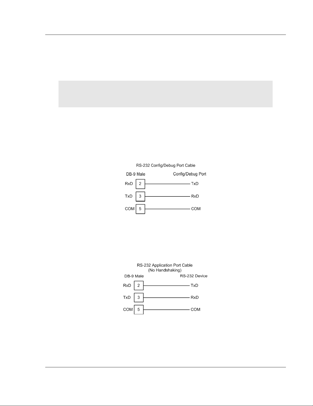
2.4.1 RS-232 Configuration/Debug Port
This port is physically an RJ45 connection. An RJ45 to DB-9 adapter cable is
included with the module. This port permits a PC based terminal emulation
program to view configuration and status data in the module and to control the
module. The cable for communications on this port is shown in the following
diagram:
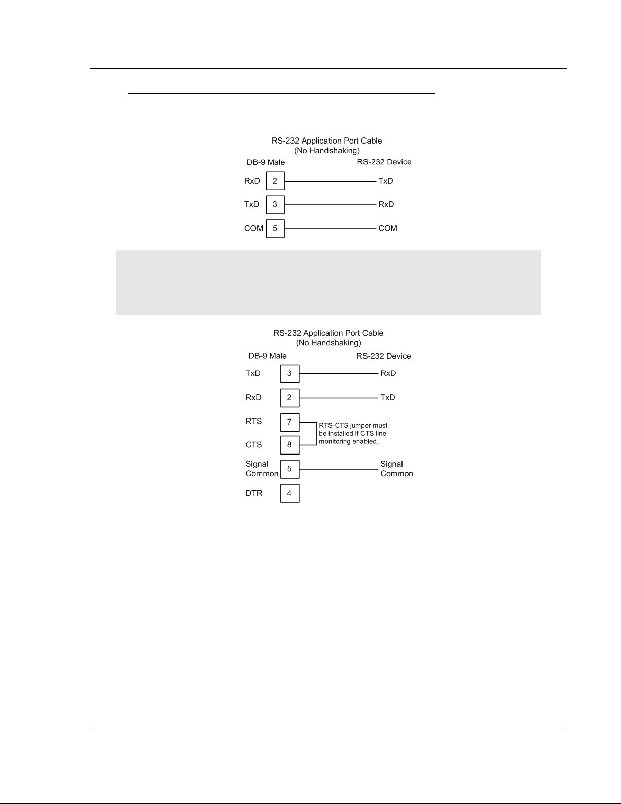
2.4.2 RS-232 Application Port(s)
When the RS-232 interface is selected, the use of hardware handshaking
(control and monitoring of modem signal lines) is user definable. If no hardware
handshaking will be used, here are the cable pinouts to connect to the port.
ProSoft Technology, Inc. Page 19 of 342
February 20, 2013
Page 20
Preparing the MVI-ADM Module MVI-ADM ♦ 'C' Programmable
Developer's Guide 'C' Programmable Application Development Module
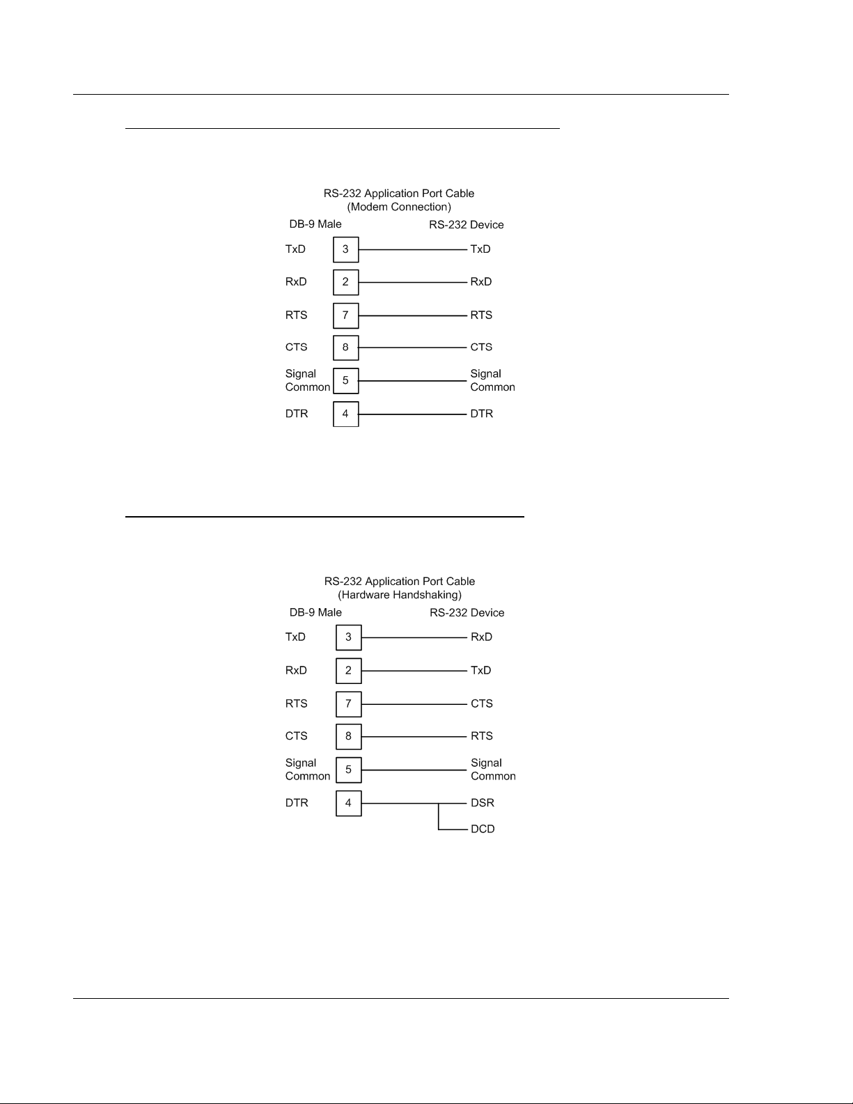
RS-232: Modem Connection (Hardware Handshaking Required)
This type of connection is required between the module and a modem or other
communication device.
The "Use CTS Line" parameter for the port configuration should be set to 'Y' for
most modem applications.
RS-232: Null Modem Connection (Hardware Handshaking)
This type of connection is used when the device connected to the module
requires hardware handshaking (control and monitoring of modem signal lines).
Page 20 of 342 ProSoft Technology, Inc.
February 20, 2013
Page 21
MVI-ADM ♦ 'C' Programmable Preparing the MVI-ADM Module
'C' Programmable Application Development Module Developer's Guide
RS-232: Null Modem Connection (No Hardware Handshaking)
This type of connection can be used to connect the module to a computer or field
device communication port.
Note: For most null modem connections where hardware handshaking is not required, the Use
CTS Line parameter should be set to N and no jumper will be required between Pins 7 (RTS) and 8
(CTS) on the connector. If the port is configured with the Use CTS Line set to Y, then a jumper is
required between the RTS and the CTS lines on the port connection.
ProSoft Technology, Inc. Page 21 of 342
February 20, 2013
Page 22
Preparing the MVI-ADM Module MVI-ADM ♦ 'C' Programmable
Developer's Guide 'C' Programmable Application Development Module
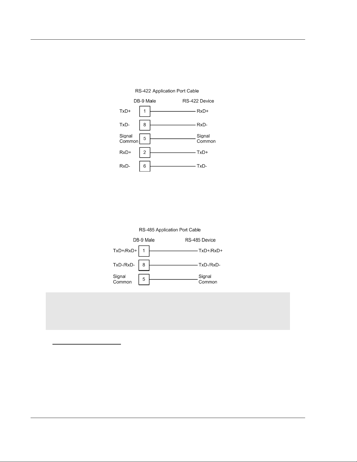
2.4.3 RS-422
The RS-422 interface requires a single four or five wire cable. The Common
connection is optional, depending on the RS-422 network devices used. The
cable required for this interface is shown below:
2.4.4 RS-485 Application Port(s)
The RS-485 interface requires a single two or three wire cable. The Common
connection is optional, depending on the RS-485 network devices used. The
cable required for this interface is shown below:
Note: Terminating resistors are generally not required on the RS-485 network, unless you are
experiencing communication problems that can be attributed to signal echoes or reflections. In
these cases, installing a 120-ohm terminating resistor between pins 1 and 8 on the module
connector end of the RS-485 line may improve communication quality.
RS-485 and RS-422 Tip
If communication in the RS-422 or RS-485 mode does not work at first, despite
all attempts, try switching termination polarities. Some manufacturers interpret +
and -, or A and B, polarities differently.
Page 22 of 342 ProSoft Technology, Inc.
February 20, 2013
Page 23
MVI-ADM ♦ 'C' Programmable Preparing the MVI-ADM Module
'C' Programmable Application Development Module Developer's Guide
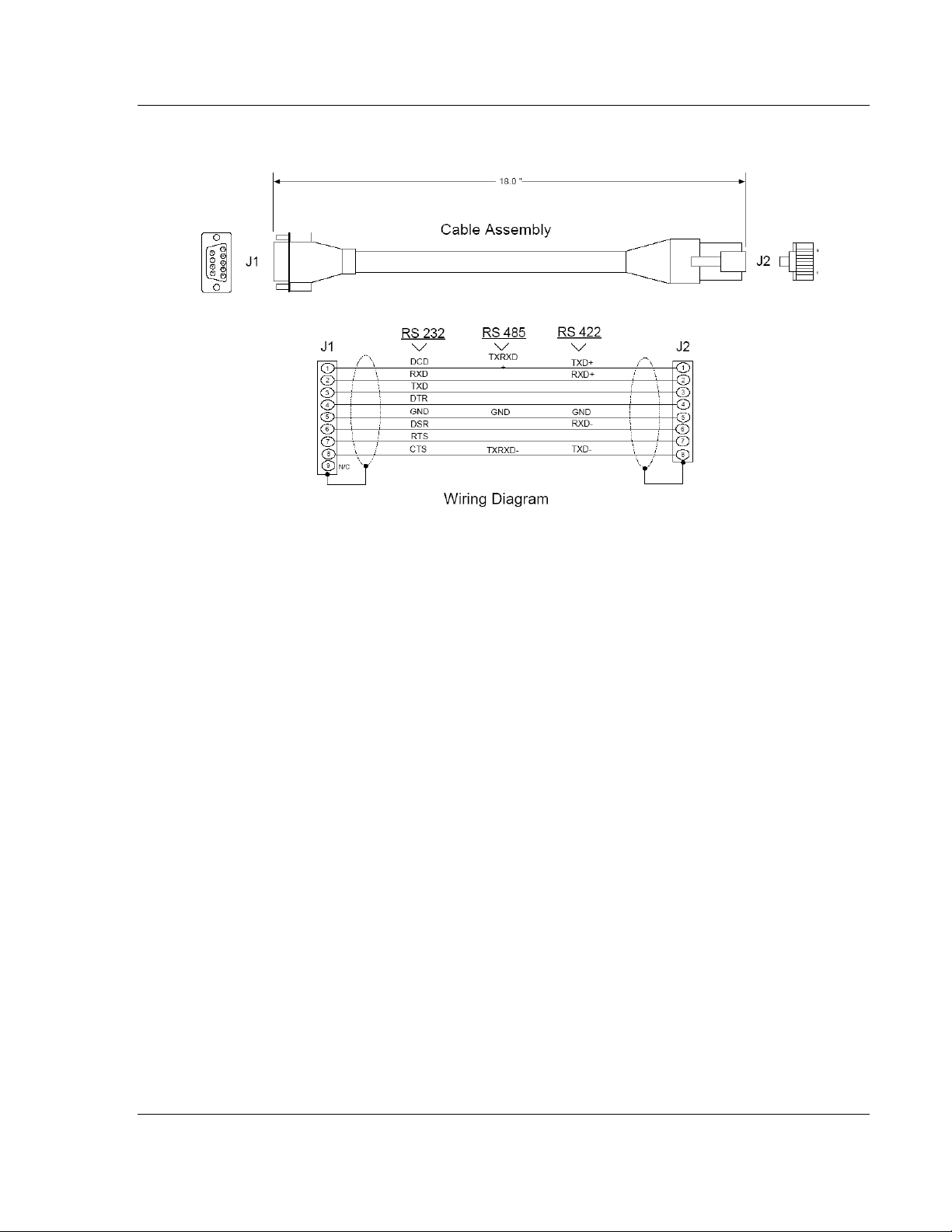
2.4.5 DB9 to RJ45 Adaptor (Cable 14)
ProSoft Technology, Inc. Page 23 of 342
February 20, 2013
Page 24

Preparing the MVI-ADM Module MVI-ADM ♦ 'C' Programmable
Developer's Guide 'C' Programmable Application Development Module
Page 24 of 342 ProSoft Technology, Inc.
February 20, 2013
Page 25

MVI-ADM ♦ 'C' Programmable Understanding the MVI-ADM API
In This Chapter
API Libraries .......................................................................................... 26
Development Tools ............................................................................... 28
Theory of Operation .............................................................................. 29
ADM Functional Blocks ......................................................................... 30
ADM API Architecture............................................................................ 59
ADM API Files ....................................................................................... 60
Backplane API Files .............................................................................. 64
Serial API Files ...................................................................................... 66
Side-Connect API Files ......................................................................... 67
'C' Programmable Application Development Module Developer's Guide
3 Understanding the MVI-ADM API
The MVI ADM API Suite allows software developers to access the PLC
backplane and serial ports without needing detailed knowledge of the module’s
hardware design. The MVI ADM API Suite consists of three distinct components:
the Serial Port API, the MVI Backplane/CIP API and the ADM API.
The MVI Backplane API provides access to the processor
The Serial Port API provides access to the serial ports
The ADM API provides functions designed to ease development.
In addition to the MVI Backplane API, MVI71 also provides the MVI Side-
Connect API as an alternative interface.
Applications for the MVI ADM module may be developed using industry-standard
DOS programming tools and the appropriate API components.
This section provides general information pertaining to application development
for the MVI ADM module.
ProSoft Technology, Inc. Page 25 of 342
February 20, 2013
Page 26

Understanding the MVI-ADM API MVI-ADM ♦ 'C' Programmable
Developer's Guide 'C' Programmable Application Development Module
3.1 API Libraries
Each API provides a library of function calls. The library supports any
programming language that is compatible with the Pascal calling convention.
Each API library is a static object code library that must be linked with the
application to create the executable program. It is distributed as a 16-bit large
model OMF library, compatible with Digital Mars C++ or Borland development
tools.
Note: The following compiler versions are intended to be compatible with the MVI module API:
Digital Mars C++ 8.49
Borland C++ V5.02
More compilers will be added to the list as the API is tested for compatibility with them.
3.1.1 Calling Convention
The API library functions are specified using the 'C' programming language
syntax. To allow applications to be developed in other industry-standard
programming languages, the standard Pascal calling convention is used for all
application interface functions.
3.1.2 Header File
A header file is provided along with each library. This header file contains API
function declarations, data structure definitions, and miscellaneous constant
definitions. The header file is in standard 'C' format.
3.1.3 Sample Code
A sample application is provided to illustrate the usage of the API functions. Full
source for the sample application is provided. The sample application may be
compiled using Digital Mars C++ or Borland C++.
Important: The sample code and libraries in the 1756-MVI-Samples folder are not compatible with,
and are not supported for, the Digital Mars compiler.
Page 26 of 342 ProSoft Technology, Inc.
February 20, 2013
Page 27

MVI-ADM ♦ 'C' Programmable Understanding the MVI-ADM API
'C' Programmable Application Development Module Developer's Guide
3.1.4 Multi-threading Considerations
The DOS 6-XL operating system supports the development of multi-threaded
applications.
Note: The multi-threading library kernel.lib in the DOS folder on the distribution CD-ROM is
compiler-specific to Borland C++ 5.02. It is not compatible with Digital Mars C++ 8.49. ProSoft
Technology, Inc. does not support multi-threading with Digital Mars C++ 8.49.
Note: The ADM DOS 6-XL operating system has a system tick of 5 milliseconds. Therefore, thread
scheduling and timer servicing occur at 5ms intervals. Refer to the DOS 6-XL Developer’s Guide
on the distribution CD-ROM for more information.
Multi-threading is also supported by the API.
DOS and cipapi libraries have been tested and are thread-safe for use in
multi-threaded applications.
MVIbp and MVIsp libraries are safe to use in multi-threaded applications with
the following precautions: If you call the same MVIbp or MVIsp function from
multiple threads, you will need to protect it, to prevent task switches during
the function's execution. The same is true for different MVIbp or MVIsp
functions that share the same resources (for example, two different functions
that access the same read or write buffer).
WARNING: ADM and ADMNET libraries are not thread-safe. ProSoft Technology, Inc. does not
support the use of ADM and ADMNET libraries in multi-threaded applications.
ProSoft Technology, Inc. Page 27 of 342
February 20, 2013
Page 28

Understanding the MVI-ADM API MVI-ADM ♦ 'C' Programmable
Developer's Guide 'C' Programmable Application Development Module
3.2 Development Tools
An application that is developed for the MVI ADM module must be executed from
the module’s Flash ROM disk. Tools are provided with the API to build the disk
image and download it to the module’s Config/Debug port.
Page 28 of 342 ProSoft Technology, Inc.
February 20, 2013
Page 29

MVI-ADM ♦ 'C' Programmable Understanding the MVI-ADM API
'C' Programmable Application Development Module Developer's Guide
3.3 Theory of Operation
3.3.1 ADM API
The ADM API is one component of the MVI ADM API Suite. The ADM API
provides a simple module level interface that is portable between members of the
MVI Family. This is useful when developing an application that implements a
serial protocol for a particular device, such as a scale or bar code reader. After
an application has been developed, it can be be used on any of the MVI family
modules.
ProSoft Technology, Inc. Page 29 of 342
February 20, 2013
Page 30
Understanding the MVI-ADM API MVI-ADM ♦ 'C' Programmable
Developer's Guide 'C' Programmable Application Development Module
3.4 ADM Functional Blocks
3.4.1 Database
The database functions of the ADM API allow the creation of a database in
memory to store data to be accessed via the backplane interface and the
application ports. The database consists of word registers that can be accessed
as bits, bytes, words, longs, floats or doubles. Functions are provided for reading
and writing the data in the various data types. The database serves as a holding
area for exchanging data with the processor on the backplane, and with a foreign
device attached to the application port. Data transferred into the module from the
processor can be requested via the serial port. Conversely, data written into the
module database by the foreign device can be transferred to the processor over
the backplane.
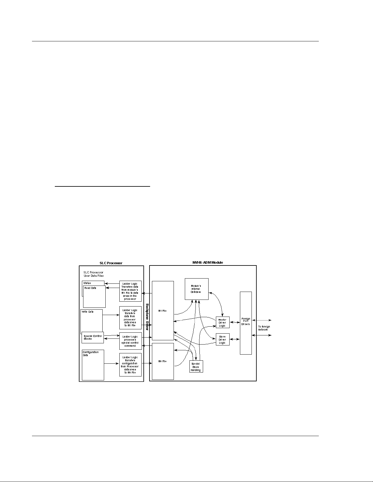
3.4.2 Backplane Communications
MVI46 Backplane Data Transfer
The MVI46-ADM module communicates directly over the backplane. All data for
the module is contained in the module's M1 file. Data is moved between the
module and the SLC processor across the backplane using the module's M-files.
The SLC scan rate and the communication load on the module determine the
update frequency of the M-files. The COP instruction can be used to move data
between user data files and the module's M1 file.
The following illustration shows the data transfer method used to move data
between the SLC processor, the MVI46-ADM module and the foreign network.
All data transferred between the module and the processor over the backplane is
through the M0 and M1 files. Ladder logic must be written in the SLC processor
to interface the M-file data with data defined in the user-defined data files in the
SLC.
Page 30 of 342 ProSoft Technology, Inc.
February 20, 2013
Page 31

MVI-ADM ♦ 'C' Programmable Understanding the MVI-ADM API
Block Range
Descriptions
9000
Configuration request from module
9001
Configuration ready from controller
9997
Write configuration to controller
9998
Warm-boot control block
9999
Cold-boot control block
'C' Programmable Application Development Module Developer's Guide
All data used by the module is stored in its internal database. The following
illustration shows the layout of the database:
User data contained in this database is continuously read from the M1 file. The
configuration data is only updated in the M1 file after each configuration request
by the module to the SLC. All data in the M1 file is available to devices on the
foreign networks. This permits data to be transferred from these devices to the
SLC using the user data area. Additionally, remote devices can alter the
module's configuration, read the status data and issue control commands. Block
identification codes define specific functions to the module.
The block identification codes used by the module are listed below:
Each block has a defined structure depending on the data content and the
function of the data transfer as defined in the following topics.
Normal Data Transfer
This version of the module provides for direct access to the data in the module.
All data related to the module is stored in the module’s M1 file. To read data from
the module, use the COP instruction to copy data from the module’s M1 file to a
user data file. To write data to the module, use the COP instruction to copy data
from a user file to the module’s M1 file. Registers 0 to 4999 should be used for
user data. All other registers are reserved for other module functions.
ProSoft Technology, Inc. Page 31 of 342
February 20, 2013
Page 32

Understanding the MVI-ADM API MVI-ADM ♦ 'C' Programmable
M0 Offset
Description
Length
0
9001
1
1 to 6
Backplane Set Up
6
7 to 15
Port 1 Configuration
9
16 to 24
Port 2 Configuration
9
M0 Offset
Description
Length
0
9997
1
1 to 6
Backplane Set Up
6
7 to 15
Port 1 Configuration
9
16 to 24
Port 2 Configuration
9
Developer's Guide 'C' Programmable Application Development Module
Configuration Data Transfer Block (9000)
When the module performs a restart operation, it will request configuration
information from the SLC processor. This data is transferred to the module in a
specially formatted write block in the M0 file. The module will poll for this
information by placing the value 9000 in word 0 of the M0 file. The ladder logic
must construct the requested block in order to configure the module. The format
of the block for configuration is given in the following section.
Module Configuration Data Block (9001)
This block sends configuration information from the processor to the module. The
data is transferred in a block with an identification code of 9001. The structure of
the block is displayed below:
If there are any errors in the configuration, the bit associated with the error will be
set in one of the two configuration error words. The error must be corrected
before the module starts operating.
Special Function Blocks
Special Function blocks are special blocks used to control the module or request
special data from the module. The current version of the software supports three
special function blocks: write configuration, warm boot and cold boot.
Write Configuration Block (9997)
This block is sent from the processor, and causes the module to write its current
configuration back to the processor. This function is used when the module’s
configuration has been altered remotely using database write operations. The
write block contains a value of 9997 in the first word. The module will respond
with a block containing the module configuration data. Ladder logic must handle
the receipt of the block. The block transferred from the module is as follows:
Page 32 of 342 ProSoft Technology, Inc.
February 20, 2013
Page 33

MVI-ADM ♦ 'C' Programmable Understanding the MVI-ADM API
M1 Offset
Description
Length
7800
9997
1
M1 Offset
Description
Length
7800
9998
1
M1 Offset
Description
Length
7800
9999
1
'C' Programmable Application Development Module Developer's Guide
Ladder logic must process this block of information and place the data received
in the correct data files in the . The processor requests this block of information
using the following write block:
Warm Boot Block (9998)
This block is sent from the SLC processor to the module when the module is
required to perform a warm-boot (software reset) operation. This block is
commonly sent to the module any time configuration data modifications are made
in the configuration data area. This will cause the module to read the new
configuration information and to restart. The following table describes the format
of the control block.
Cold Boot Block (9999)
This block is sent from the SLC processor to the module when the module is
required to perform the cold boot (hardware reset) operation. This block is sent to
the module when a hardware problem is detected by the ladder logic that
requires a hardware reset. The following table describes the format of the control
block.
MVI56 Backplane Data Transfer
The MVI56-ADM module communicates directly over the backplane. Data is
paged between the module and the ControlLogix processor across the backplane
using the module's input and output images. The update frequency of the images
is determined by the scheduled scan rate defined by the user for the module, and
by the communication load on the module. Typical updates are in the range of 2
to 10 milliseconds.
This bi-directional transference of data is accomplished by the module filling in
data in the module's input image to send to the processor. Data in the input
image is placed in the Controller Tags in the processor by the ladder logic. The
input image for the module is set to 250 words. This large data area permits fast
throughput of data between the module and the processor.
The processor inserts data to the module's output image to transfer to the
module. The module's program extracts the data and places it in the module's
internal database. The output image for the module is set to 248 words. This
large data area permits fast throughput of data from the processor to the module.
ProSoft Technology, Inc. Page 33 of 342
February 20, 2013
Page 34

Understanding the MVI-ADM API MVI-ADM ♦ 'C' Programmable
5000 registers for user data
0
Register Data
4999
2000 words of configuration and
status data
5000
Status and Config
6999
Developer's Guide 'C' Programmable Application Development Module
The following illustration shows the data transfer method used to move data
between the ControlLogix processor, the MVI56-ADM module and the foreign
device.
All data transferred between the module and the processor over the backplane is
through the input and output images. Ladder logic must be written in the
ControlLogix processor to interface the input and output image data with data
defined in the Controller Tags.
All data used by the module is stored in its internal database. The following
illustration shows the layout of the database:
Module’s Internal Database Structure
Data contained in this database is paged through the input and output images by
coordination of the ControlLogix ladder logic and the MVI56-ADM module's
program. Up to 248 words of data can be transferred from the module to the
processor at a time. Up to 247 words of data can be transferred from the
processor to the module. Each image has a defined structure depending on the
data content and the function of the data transfer.
Page 34 of 342 ProSoft Technology, Inc.
February 20, 2013
Page 35

MVI-ADM ♦ 'C' Programmable Understanding the MVI-ADM API
Offset
Description
Length
0
Write Block ID
1
1 to 200
Write Data
200
201 to 247
Spare
47
Offset
Description
Length
0
Reserved
1
1
Write Block ID
1
2 to 201
Read Data
200
202
Program Scan Counter
1
203 to 204
Product Code
2
205 to 206
Product Version
2
207 to 208
Operating System
2
209 to 210
Run Number
2
211 to 212
Not Used
2
213 to 219
Port 1 Error Status
7
220 to 226
Port 2 Error Status
7
227 to 232
Data Transfer Status
6
233
Port 1 Current Error/Index
1
234
Port 1 Last Error/Index
1
235
Port 2 Current Error/Index
1
236
Port 2 Last Error/Index
1
237 to 248
Spare
12
249
Read Block ID
1
'C' Programmable Application Development Module Developer's Guide
Normal Data Transfer
Normal data transfer includes the paging of the user data found in the module’s
internal database in registers 0 to 4999 and the status data. These data are
transferred through read (input image) and write (output image) blocks. The
structure and function of each block is discussed in the following topics.
Block Request from the Processor to the Module
These blocks of data transfer information from the processor to the module. The
following table describes the structure of the output image.
The Write Block ID is an index value used to determine the location in the
module’s database where the data will be placed. Each transfer can move up to
200 words (block offsets 1 to 200) of data.
Block Response from the Module to the Processor
These blocks of data transfer information from the module to the ControlLogix
processor. The following table describes the structure of the input image.
ProSoft Technology, Inc. Page 35 of 342
February 20, 2013
Page 36

Understanding the MVI-ADM API MVI-ADM ♦ 'C' Programmable
Offset
Description
Length
0
9000
1
1 to 6
Backplane Set Up
6
7 to 15
Port 1 Configuration
9
16 to 24
Port 2 Configuration
9
25 to 247
Spare
223
Offset
Description
Length
0
Reserved
1
1
9000
1
2
Module Configuration Errors
1 3 Port 1 Configuration Errors
1
4
Port 2 Configuration Errors
1
5 to 248
Spare
244
249
-2 or -3
1
Developer's Guide 'C' Programmable Application Development Module
The Read Block ID is an index value used to determine the location of where the
data will be placed in the ControlLogix processor controller tag array of module
read data. Each transfer can move up to 200 words (block offsets 2 to 201) of
data. In addition to moving user data, the block also contains status data for the
module. This last set of data is transferred with each new block of data and is
used for high-speed data movement.
The Write Block ID associated with the block requests data from the ControlLogix
processor. Under normal program operation, the module sequentially sends read
blocks and requests write blocks. For example, if the application uses three read
and two write blocks, the sequence will be as follows:
R1W1R2W2R3W1R1W2R2W1R3W2R1W1
This sequence will continue until interrupted by other write block numbers sent by
the controller or by a command request from a node on the network or operator
control through the module’s Configuration/Debug port.
Module Configuration Data Transfer Block (9000)
When the module performs a restart operation, it will request configuration
information from the ControlLogix processor. This data is transferred to the
module in specially formatted write blocks (output image). The module will poll for
each block by setting the required write block number in a read block (input
image).
This block sends general configuration information from the processor to the
module. The data is transferred in a block with an identification code of 9000.
The structure of the block is shown in the following table.
The read block used to request the configuration has the following structure:
If there are any errors in the configuration, the bit associated with the error will be
set in one of the three configuration error words. The error must be corrected
before the module starts operating.
Page 36 of 342 ProSoft Technology, Inc.
February 20, 2013
Page 37

MVI-ADM ♦ 'C' Programmable Understanding the MVI-ADM API
'C' Programmable Application Development Module Developer's Guide
MVI69 Backplane Data Transfer
The MVI69-ADM module communicates directly over the backplane. Data is
paged between the module and the CompactLogix processor across the
backplane using the module's input and output images. The update frequency of
the images is determined by the scheduled scan rate defined by the user for the
module and the communication load on the module. Typical updates are in the
range of 2 to 10 milliseconds.
You can configure the size of the blocks using the Block Transfer Size parameter
in the configuration file. You can configure blocks of 60, 120, or 240 words of
data depending on the number of words allowed for your own application.
This bi-directional transference of data is accomplished by the module filling in
data in the module's input image to send to the processor. Data in the input
image is placed in the Controller Tags in the processor by the ladder logic. The
input image for the module may be set to 62, 122, or 242 words depending on
the block transfer size parameter set in the configuration file.
The processor inserts data to the module's output image to transfer to the
module. The module's program extracts the data and places it in the module's
internal database. The output image for the module may be set to 61, 121, or 241
words depending on the block transfer size parameter set in the configuration
file.
The following illustration shows the data transfer method used to move data
between the CompactLogix processor and the MVI69-ADM module.
ProSoft Technology, Inc. Page 37 of 342
February 20, 2013
Page 38

Understanding the MVI-ADM API MVI-ADM ♦ 'C' Programmable
5000 registers for user data
0
Register Data
4999
3000 words of configuration and
status data
5000
Status and Config
7999
Block Range
Descriptions
-1
Status Block
0
Status Block
1 to 999
Read or write data
9998
Warm-boot control block
9999
Cold-boot control block
Developer's Guide 'C' Programmable Application Development Module
All data transferred between the module and the processor over the backplane is
through the input and output images. Ladder logic must be written in the
CompactLogix processor to interface the input and output image data with data
defined in the Controller Tags. All data used by the module is stored in its internal
database. The following illustration shows the layout of the database:
Module’s Internal Database Structure
Data contained in this database is paged through the input and output images by
coordination of the CompactLogix ladder logic and the MVI69-ADM module's
program. Up to 242 words of data can be transferred from the module to the
processor at a time. Up to 241 words of data can be transferred from the
processor to the module. The read and write block identification codes in each
data block determine the function to be performed or the content of the data
block. The block identification codes used by the module are listed below:
Each image has a defined structure depending on the data content and the
function of the data transfer.
Normal Data Transfer
Normal data transfer includes the paging of the user data found in the module’s
internal database in registers 0 to 4999 and the status data. These data are
transferred through read (input image) and write (output image) blocks. The
structure and function of each block is discussed in the following topics:
Page 38 of 342 ProSoft Technology, Inc.
February 20, 2013
Page 39

MVI-ADM ♦ 'C' Programmable Understanding the MVI-ADM API
Offset
Description
Length
0
Write Block ID
1
1 to n
Write Data
n
Offset
Description
Length
0
Read Block ID
1 1 Write Block ID
1
2 to (n+1)
Read Data
n
'C' Programmable Application Development Module Developer's Guide
Block Request from the Processor to the Module
These blocks of data transfer information from the processor to the module. The
structure of the output image used to transfer this data is shown below:
n=60, 120, or 240 depending on the Block Transfer Size parameter (refer to the configuration file).
The Write Block ID is an index value used to determine the location in the
module’s database where the data will be placed.
Block Response from the Module to the Processor
These blocks of data transfer information from the module to the CompactLogix
processor. The structure of the input image used to transfer this data is shown
below:
n=60, 120, or 240 depending on the Block Transfer Size parameter (refer to the configuration file).
The Read Block ID is an index value used to determine the location of where the
data will be placed in the CompactLogix processor controller tag array of module
read data. The number of data words per transfer depends on the configured
Block Transfer Size parameter in the configuration file (possible values are 60,
120, or 240).
The Write Block ID associated with the block requests data from the
CompactLogix processor. Under normal program operation, the module
sequentially sends read blocks and requests write blocks. For example, if the
application uses three read and two write blocks, the sequence will be as follows:
R1W1R2W2R3W1R1W2R2W1R3W2R1W1
This sequence will continue until interrupted by other write block numbers sent by
the controller or by a command request from a node on the network or operator
control through the module’s Configuration/Debug port.
The following example shows a typical backplane communication application.
If the backplane parameters are configured as follows:
Read Register Start: 0
Read Register Count: 480
Write Register Start: 480
Write Register Count: 480
ProSoft Technology, Inc. Page 39 of 342
February 20, 2013
Page 40

Understanding the MVI-ADM API MVI-ADM ♦ 'C' Programmable
Developer's Guide 'C' Programmable Application Development Module
The backplane communication would be configured as follows:
Database address 0 to 479 will be continuously transferred from the module to
the processor. Database address 480 to 959 will continuously be transferred
from the processor to the module.
The Block Transfer Size parameter basically configures how the Read Data and
Write Data areas are broken down into data blocks (60, 120, or 240).
If Block Transfer Size = 60:
Page 40 of 342 ProSoft Technology, Inc.
February 20, 2013
Page 41

MVI-ADM ♦ 'C' Programmable Understanding the MVI-ADM API
'C' Programmable Application Development Module Developer's Guide
If Block Transfer Size = 120:
ProSoft Technology, Inc. Page 41 of 342
February 20, 2013
Page 42

Understanding the MVI-ADM API MVI-ADM ♦ 'C' Programmable
Offset
Description
Length
0
9998
1
1 to n
Spare
n
Developer's Guide 'C' Programmable Application Development Module
If Block Transfer Size = 240:
Warm Boot Block (9998)
This block is sent from the processor to the module (output image) when the
module is required to perform a warm-boot (software reset) operation. The
following table describes the format of the control block.
n=60, 120, or 240 depending on the Block Transfer Size parameter (refer to the configuration file).
Page 42 of 342 ProSoft Technology, Inc.
February 20, 2013
Page 43

MVI-ADM ♦ 'C' Programmable Understanding the MVI-ADM API
'C' Programmable Application Development Module Developer's Guide
MVI71 Backplane Data Transfer
The MVI71-ADM module communicates directly over the backplane. Data is
paged between the module and the PLC processor across the backplane using
the module's input and output images or directly to the processor using the sideconnect interface (requires a side-connect adapter). The update frequency of the
images is determined by the scheduled scan rate defined by the user for the
module and the communication load on the module. Typical updates are in the
range of 2 to 10 milliseconds.
This bi-directional transference of data is accomplished by the module filling in
data in the module's input image to send to the processor. Data in the input
image is placed in the Controller Tags in the processor by the ladder logic. The
input image for the module is set to 64 words. This large data area permits fast
throughput of data between the module and the processor.
The processor inserts data to the module's output image to transfer to the
module. The module's program extracts the data and places it in the module's
internal database. The output image for the module is set to 64 words. This large
data area permits fast throughput of data from the processor to the module.
The following illustration shows the data transfer method used to move data
between the PLC processor, the MVI71-ADM module and the foreign device.
Block Transfer
The following illustration shows the data transfer operations used when using the
side-connect interface (requires the side-connect adapter):
ProSoft Technology, Inc. Page 43 of 342
February 20, 2013
Page 44

Understanding the MVI-ADM API MVI-ADM ♦ 'C' Programmable
5000 registers for user data
0
Register Data
4999
3000 words of configuration and
status data
5000
Status and Config
7999
Developer's Guide 'C' Programmable Application Development Module
Side-Connect
When the side connect interface is used, data is transferred directly between the
processor and the module. The module's program interfaces directly to the set of
user data files established in the PLC to pass all data between the two devices.
No ladder logic is required for data transfer, only the establishment of the data
files.
All data transferred between the module and the processor over the backplane is
through the input and output images. Ladder logic must be written in the PLC
processor to interface the input and output image data with data defined in the
Controller Tags. All data used by the module is stored in its internal database.
Module’s Internal Database Structure
Data contained in this database is paged through the input and output images by
coordination of the PLC ladder logic and the MVI71-ADM module's program. Up
to 60 words of data can be transferred from the module to the processor at a
time. Up to 60 words of data can be transferred from the processor to the
module. Each image has a defined structure depending on the data content and
the function of the data transfer.
Page 44 of 342 ProSoft Technology, Inc.
February 20, 2013
Page 45

MVI-ADM ♦ 'C' Programmable Understanding the MVI-ADM API
Offset
Description
Length
0
Write Block ID
1
1 to 60
Write Data
60
61 to 63
Spare
3
Offset
Description
Length
0
Read Block ID
1
1
Write Block ID
1
2 to 61
Read Data
60
62 to 63
Spare
2
'C' Programmable Application Development Module Developer's Guide
Normal Data Transfer
Normal data transfer includes the paging of the user data found in the module’s
internal database in registers 0 to 4999 and the status data. These data are
transferred through read (input image) and write (output image) blocks. The
structure and function of each block is discussed in the following topics.
Block Request from the Processor to the Module
These blocks of data transfer information from the PLC processor to the module.
The following table describes the structure of the output image.
The Write Block ID is an index value used to determine the location in the
module’s database where the data will be placed. Each transfer can move up to
60 words (block offsets 1 to 60) of data.
Block Response from the Module to the Processor
These blocks of data transfer information from the module to the PLC processor.
The following table describes the structure of the input image.
The Read Block ID is an index value used to determine the location of where the
data will be placed in the PLC processor user data table. Each transfer can move
up to 60 words (block offsets 2 to 61) of data.
The Write Block ID associated with the block requests data from the PLC
processor. Under normal program operation, the module sequentially sends read
blocks and requests write blocks. For example, if the application uses three read
and two write blocks, the sequence will be as follows:
R1W1R2W2R3W1R1W2R2W1R3W2R1W1
This sequence will continue until interrupted by other write block numbers sent by
the controller or by a command request from a node on the foreign network or
operator control through the module’s Configuration/Debug port.
If the ladder logic does not send a BTW instruction to the module quickly enough,
it is possible for the MVI71-ADM module to send a new BTR instruction
requesting the same write block ID.
ProSoft Technology, Inc. Page 45 of 342
February 20, 2013
Page 46

Understanding the MVI-ADM API MVI-ADM ♦ 'C' Programmable
Offset
Description
Length
0
9000
1
1 to 6
Backplane Setup
6
7 to 31
Port 1 Configuration
25
32 to 56
Port 2 Configuration
25
57 to 63
Spare
7
Offset
Description
Length
0
-2 1 1
9000
1
2
Module Configuration Errors
1
3
Port 1 Configuration Errors
1
4
Port 2 Configuration Errors
1
5 to 63
Spare
59
Developer's Guide 'C' Programmable Application Development Module
Module Configuration Data Transfer Block (9000)
When the module performs a restart operation, it will request configuration
information from the PLC processor. This data is transferred to the module in
specially formatted write blocks (output image). The module will poll for each
block by setting the required write block number in a read block (input image).
The module will request all command blocks, according to the number of
commands configured by the user for each Master port.
This block sends general configuration information from the processor to the
module. The data is transferred in a block with an identification code of 9000.
The structure of the block is displayed in the following table.
Write Block
The read block used to request the configuration has the following structure:
Read Block
If there are any errors in the configuration, the bit associated with the error will be
set in one of the three configuration error words. The error must be corrected
before the module starts operating.
Special Function Blocks
Special Function blocks are special blocks used to control the module or request
special data from the module. The current version of the software supports three
special function blocks: write configuration, warm boot and cold boot.
Page 46 of 342 ProSoft Technology, Inc.
February 20, 2013
Page 47

MVI-ADM ♦ 'C' Programmable Understanding the MVI-ADM API
Offset
Description
Length
0
-9000
1 1 -9000
1
2 to 7
Backplane Setup
6
8 to 32
Port 1 Configuration
25
33 to 57
Port 2 Configuration
25
58 to 63
Spare
6
Offset
Description
Length
0
-6000 to 6016 and -6100 to 6116
1 1 -6000 to 6016 and -6100 to 6116
1
2 to 11
Command Definition
10
12 to 21
Command Definition
10
22 to 31
Command Definition
10
32 to 41
Command Definition
10
42 to 51
Command Definition
10
52 to 61
Command Definition
10
62 to 63
Spare
2
Offset
Description
Length
0
9997
1
1 to 63
Spare
63
'C' Programmable Application Development Module Developer's Guide
Write Configuration Block (-9000)
This block is sent from the PLC processor, and causes the module to write its
current configuration back to the processor. This function is used when the
module’s configuration has been altered remotely using database write
operations. The write block contains a value of -9000 in the first word. The
module will respond with blocks containing the module configuration data. Ladder
logic must handle the receipt of these blocks. The blocks transferred from the
module are as follows:
Block -9000, General Configuration Data:
Blocks -6000 to -6003 and -6100 to 6103, Master Command List Data for ports 1
and 2, respectively:
Each of these blocks must be handled by the ladder logic for proper module
operation. The processor can request the module’s configuration by sending a
configuration read request block, block code 9997, to the module. The format of
this request block is as follows:
ProSoft Technology, Inc. Page 47 of 342
February 20, 2013
Page 48

Understanding the MVI-ADM API MVI-ADM ♦ 'C' Programmable
Offset
Description
Length
0
9998
1
1 to 63
Spare
63
Offset
Description
Length
0
9999
1
1 to 63
Spare
63
Developer's Guide 'C' Programmable Application Development Module
When the module receives this command block, it transfers the module’s current
configuration to the processor. If the block transfer interface is used, the blocks
defined in the previous tables (-9000 and -6000 series blocks) will be sent from
the module. If the side-connect interface is used, the user data files will be
updated directly by the module.
Warm Boot Block (9998)
This block is sent from the PLC processor to the module (output image) when the
module is required to perform a warm-boot (software reset) operation. This block
is commonly sent to the module any time configuration data modifications are
made in the controller tags data area. This will cause the module to read the new
configuration information and to restart. The following table describes the format
of the control block.
Cold Boot Block (9999)
This block is sent from the PLC processor to the module (output image) when the
module is required to perform the cold boot (hardware reset) operation. This
block is sent to the module when a hardware problem is detected by the ladder
logic that requires a hardware reset. The following table describes the format of
the control block.
MVI94 Backplane Data Transfer
Central to the functionality of the module is the database. This database is used
as the interface between remote foreign slave devices or foreign master devices
and the Flex I/O bus. The size, content and structure of the database are
completely user defined.
Page 48 of 342 ProSoft Technology, Inc.
February 20, 2013
Page 49

MVI-ADM ♦ 'C' Programmable Understanding the MVI-ADM API
'C' Programmable Application Development Module Developer's Guide
The Flex I/O bus reads data from and write data to the database using the
backplane interface. The module interfaces data contained in remote foreign
slave devices to the database when using the MVI94-ADM as a master. User
commands are issued out of the master port from a command list. These
commands gather or control data in the foreign slave devices. When configured
as a slave, control information from the foreign master and data from the
processor are exchanged over the backplane. The following illustration shows
the relationships discussed above:
ProSoft Technology, Inc. Page 49 of 342
February 20, 2013
Page 50

Understanding the MVI-ADM API MVI-ADM ♦ 'C' Programmable
Developer's Guide 'C' Programmable Application Development Module
Data Transfer
Data is transferred over the backplane using the module’s input and output
images. The module is configured with an eight-word input image and a sevenword output image. The module and the Flex processor use these images to
page data and commands. The input image is set (written) by the module and is
read by the Flex processor. The output image is set (written) by the Flex
processor and read by the module. The following illustration shows this
relationship.
The module’s program is responsible for setting the block identification code
used to identify the data block written and the block identification code of the
block it wants to read from the processor. User configuration information
determines the read (Read Start Register) and write (Write Start Register)
locations in the database and the amount of data transferred (Read Register
Count and Write Register Count).
Each read and write operation transfers a six-word data area. The write operation
contains a two-word header that defines the block identification code of the write
data and the block identification code of the read block requested. These
identification codes are in the range of 0 to 666. A value of zero indicates that the
block contains no data and should be ignored. The first valid block identification
code is one and refers to the first block of six words to be read or written.
Page 50 of 342 ProSoft Technology, Inc.
February 20, 2013
Page 51

MVI-ADM ♦ 'C' Programmable Understanding the MVI-ADM API
'C' Programmable Application Development Module Developer's Guide
The module and the processor constantly monitor input and output images. How
does either one know when a new block of data is available? Recognizing a
change in the header information of the image (word 0) solves the problem. For
example, when the module recognizes a different value in the first word of the
output image, new read data is available. When the processor recognizes a new
value in the first word of the input image, new write data is available. This
technique requires the storage of the previously processed data block
identification code. The following illustration shows the normal sequence of
events for data transfer:
1 During program initialization, the write and read block identification codes are
set to one. The last block read variable is set to zero.
2 The program copies the first six-word block of the database starting at the
user defined Write Start Register to the input image (words 2 to 7). It then
sets the current read block code in word 1 of the input image. To "trigger" the
write operation, the program places the current write block code into word 0
of the input image.
ProSoft Technology, Inc. Page 51 of 342
February 20, 2013
Page 52

Understanding the MVI-ADM API MVI-ADM ♦ 'C' Programmable
Type
Number
Description
R/W
1 to 666
Data blocks used to transfer data from the module to the
backplane and from the backplane to the module. The module's
input/output images are used for the data transfers.
R
9998
Warm boot the module. When the module receives this block, it
will reset all program values using the configuration data.
R
9999
Cold boot the module. When the module receives this block, it
will perform a hardware restart.
Developer's Guide 'C' Programmable Application Development Module
The Flex processor recognizes a new value in word 0 of the input image
(based on the last_write_block_code not equal to write_block_code) in its
ladder logic. The ladder logic computes the offset into the file based on the
following formula:
write_file_offset = (write_block_code - 1) * 6
The new data contained in the input image (words 2 to 7) is copied to the
offset in the processor’s user data file. The last_write_block_code storage
register in the processor is updated with the new write_block_code.
Note: If the data area transferred from the module exceeds the size of a single user file in the Flex
processor, logic will be required to handle multiple files.
3 The ladder logic next examines the value of the read_block_code and
computes the offset into the read data file as follows:
read_file_offset = (read_block_code - 1) * 6
The required 6-word, read data is copied to the module’s output image
(words 1 to 6). To "trigger" the transfer operation, the ladder logic moves the
read_block_code into word 0 of the output image.
4 The module’s program recognizes the new read_block_code. It transfers the
data to the correct offset in the database using the following function:
offset = Read_Start_Register + (read_block_code - 1) * 6
The module sets the last_read_block_code to the value of read_block_code.
5 The module now selects the next read and write blocks. The data for the write
operation is placed in the input image and the read_block_code is set. The
module "triggers" the transfer operation by setting the new write_block_code
in word 0 of the input image. The sequence continues at step 3.
The discussion above is for normal data transfer operation. The following table
lists the block identification codes used by the module.
Block Identification Codes
Page 52 of 342 ProSoft Technology, Inc.
February 20, 2013
Page 53

MVI-ADM ♦ 'C' Programmable Understanding the MVI-ADM API
'C' Programmable Application Development Module Developer's Guide
Data is transferred between the processor and the module using the block
identification codes of 1 to 666. The other block codes control the module from
the processors ladder logic. They are implemented when the ladder logic needs
to control the module. In order to use one of the blocks, the ladder logic inserts
the data and code in the output image of the module. The data should be set
before the code is placed in the block. This operation should be performed after
the receipt of a new write block from the module. Each set of codes is described
in the following topics.
Warm Boot Block (9998)
This block does not contain any data. When the processor places a value of
9998 in word 0 of the output image, the module will perform a warm-start. This
involves clearing the configuration and all program status data. Finally, the
program will load in the configuration information from the Flash ROM and begin
running. There is no positive response to this message other than the status data
being set to zero and the block polling starting over.
Cold Boot Block (9999)
This block does not contain any data. When the processor places a value of
9999 in word 0 of the output image, the module will perform a hardware restart.
This will cause the module to reboot and reload the program. There is no positive
response to this message other than the status data being set to zero and the
block polling starting over.
3.4.3 Serial Communications
The developer must provide the serial communication driver code. The serial API
has many useful functions to facilitate writing a driver. A sample communication
driver is included in the example programs.
3.4.4 Main_app.c
The application starts by opening the ADM API, initializing variables, structure
members and pointers to structures. Next, the database is created and initialized
to 0. The backplane driver is then opened and startup() is called. The function
startup(), loads the module configuration, initializes the com. ports and finishes
by showing the application version information. Now the main loop is entered.
The processing that occurs in the loop cycles through the backplane transfer
logic, the com. driver, and the debug menu logic. If the application is quit by the
user, shutdown() is called. The function shutdown() closes the com. ports, closes
the backplane driver, closes the database and closes the ADM API.
ProSoft Technology, Inc. Page 53 of 342
February 20, 2013
Page 54

Understanding the MVI-ADM API MVI-ADM ♦ 'C' Programmable
Developer's Guide 'C' Programmable Application Development Module
3.4.5 Debugprt.c
The debug port code shows how a sub-menu can be added to the main menu.
When "X" (Auxiliary menu) is selected, the function pointed to by user_menu_ptr
in the interface structure: that is, interface.user_menu_ptr = DebugMenu;. The
function name is DebugMenu() but it can be named anything the developer
wishes. Code can be added for additional menu items within DebugMenu() by
adding additional case statements. It is recommended that if long strings must be
sent to the debug port, that the output buffering is used. An example of this is the
"?" case. The string is placed into the buffer (interface_ptr->buff) using
sprintf. interface_ptr->buff_ch is the pointer to the first character of the string
and should be set to 0. interface_ptr->buff_len must be set to the number of
characters placed into the buffer. The writing of the characters is handled when
ADM_ProcessDebug() is called.
Example:
sprintf(interface_ptr->buff,"\nAUXILLIARY MENU\n\
?=Display Menu\n\
1=Selection 1\n\
2=Selection 2\n\
M=Main Menu\n\n");
interface_ptr->buff_ch = 0;
interface_ptr->buff_len = strlen(interface_ptr->buff);
3.4.6 MVIcfg.c
The configuration section of the example code is intended to qualify the module
configuration after it is transferred to the module. The logic must be modified to
match any changes to the configuration data structure.
MVI46
For the MVI46, the function ProcessCfg() checks the data values transferred
from the configuration file in the SLC processor. If configuration values are added
to the configuration structure in the SLC, then logic to perform boundary checking
on the added data must be added to ProcessCfg().
MVI56
In the case of the MVI56, the function ProcessCfg() checks the data values
transferred from the configuration data tags in the ControlLogix processor. If data
tags are added to the configuration structure in the ControlLogix, then logic to
perform boundary checking on the added data must be added to ProcessCfg().
Page 54 of 342 ProSoft Technology, Inc.
February 20, 2013
Page 55

MVI-ADM ♦ 'C' Programmable Understanding the MVI-ADM API
'C' Programmable Application Development Module Developer's Guide
MVI69
The MVI69 stores its configuration in EEPROM, downloaded via the debug port.
The EEPROM has 129 KB of configuration space. The function ReadCfg()
parses the file and qualifies the configuration data. The configuration file uses
headings in square brackets to define the sections. Each item is parsed using the
ADM RAM file functions. The file is searched for a configuration item. If a match
is found, the value is saved into a variable. Boundary checking is then performed
on the data. An example of a configuration item search follows:
ptr= ADM_RAM_find_Section (adm_handle, "[Port]");
ports[0].stopbits = ADM_RAM_GetInt(adm_handle, "[Port]");
switch(ports[0].stopbits)
{
case 1:
ports[0].stopbits = STOPBITS1;
case 2:
ports[0].stopbits = STOPBITS2;
break;
default:
ports[0].CfgErr |= 0x0100;
ports[0].stopbits = STOPBITS1;
}
Here the file is being parsed for "Stop Bits" under the heading of [Port]. Refer to
the example code for a sample configuration file.
Because a pointer to a function is used by the ADM API to access this function,
the name can be anything the developer wishes. However, the function must
take the same arguments and the same return value.
MVI71
In the case of the MVI71, the function ProcessCfg() checks the data values
transferred from the configuration file in the PLC processor. If configuration
values are added to the configuration structure in the PLC, then the logic to
perform boundary checking on the added data must be added to ProcessCfg().
ProSoft Technology, Inc. Page 55 of 342
February 20, 2013
Page 56

Understanding the MVI-ADM API MVI-ADM ♦ 'C' Programmable
Developer's Guide 'C' Programmable Application Development Module
MVI94
The MVI94 stores its configuration in flash memory, downloaded via the debug
port. The function ReadCfg() parses the file and qualifies the configuration data.
The configuration file uses headings in square brackets to define the sections.
Each item is parsed using the ADM flash file functions. The file is searched for a
configuration item. If a match is found, the value is saved into a variable.
Boundary checking is then performed on the data. An example of a configuration
item search follows:
ports[0].stopbits = ADM_FileGetInt("[Port]", "Stop Bits");
switch(ports[0].stopbits)
{
case 1:
ports[0].stopbits = STOPBITS1;
case 2:
ports[0].stopbits = STOPBITS2;
break;
default:
ports[0].CfgErr |= 0x0100;
ports[0].stopbits = STOPBITS1;
}
Here the file is being parsed for "Stop Bits" under the heading of [Port]. Refer to
the example code for a sample configuration file.
Because a pointer to a function is used by the ADM API to access this function,
the name can be anything the developer wishes. However, the function must
take the same arguments and the same return value.
3.4.7 Commdrv.c
The communication driver demonstrates how a simple driver might be written.
The driver is an ASCII slave that echoes the characters it receives back to the
host. The end of a new string is detected when an LF is received. The
communication driver is called for each application port on the module. The
following illustration shows information on the communication driver state
machine.
The state machine is entered at state -1. It waits there until data is detected in
the receive buffer. When data is present, the state machine advances to state 1.
It will remain in state 1 receiving data from the buffer until a line feed (LF) is
found. At this time the state advances to 2. The string will be saved to the
database and the state changes to 2000.
Page 56 of 342 ProSoft Technology, Inc.
February 20, 2013
Page 57

MVI-ADM ♦ 'C' Programmable Understanding the MVI-ADM API
'C' Programmable Application Development Module Developer's Guide
State 2000 contains a sub-state machine for handling the sending of the
response. State 2000:2 sets RTS on. The state now changes to 2000:3. The
driver now waits for the RTS timeout period to expire. When it does, it checks for
CTS to be asserted. If CTS detection is disabled or CTS is detected, RTS is set
to off (CTS enabled only) and the state advances to 2000:4. Otherwise it is an
error and RTS is set to off and returns to state -1. The response is now placed in
the transmit buffer. The state is advanced to 2000:5 where it waits for the
response to be sent. If the response times out, RTS is set to off and the state
returns to -1. If the response is sent before timeout, the state changes to 2000:6
where it waits for the RTS timer to expire. When the timer expires, RTS is set to
off and the state returns to -1 where it is ready for the next packet.
RS-485 Programming Note
Hardware
The serial port has two driver chips, one for RS-232 and one for RS-422/485.
The Request To Send (RTS) line is used for hardware handshaking in RS-232
and to control the transmitter in RS-422/485.
In RS-485, only one node can transmit at a time. All nodes should default to
listening (RTS off) unless transmitting. If a node has its RTS line asserted, then
all other communication is blocked. An analogy for this is a 2-way radio system
where only one person can speak at a time. If someone holds the talk button,
then they cannot hear others transmitting.
In order to have orderly communication, a node must make sure no other nodes
are transmitting before beginning a transmission. The node needing to transmit
will assert the RTS line then transmit the message. The RTS line must be deasserted as soon as the last character is transmitted. Turning RTS on late or off
early will cause the beginning or end of the message to be clipped resulting in a
communication error. In some applications it may be necessary to delay between
RTS transitions and the message. In this case RTS would be asserted, wait for
delay time, transmit message, wait for delay time, and de-assert RTS.
ProSoft Technology, Inc. Page 57 of 342
February 20, 2013
Page 58

Understanding the MVI-ADM API MVI-ADM ♦ 'C' Programmable
Developer's Guide 'C' Programmable Application Development Module
Software
The following is a code sample designed to illustrate the steps required to
transmit in RS-485. Depending on the application, it may be necessary to handle
other processes during this transmit sequence and to not block. This is simplified
to demonstrate the steps required.
int length = 10; // send 10 characters
int CharsLeft;
BYTE buffer[10];
// Set RTS on
MVIsp_SetRTS(COM2, ON);
// Optional delay here (depends on application)
// Transmit message
MVIsp_PutData(COM2, buffer, &length, TIMEOUT_ASAP);
// Check to see that message is done
MVIsp_GetCountUnsent(COM2, &CharsLeft);
// Keep checking until all characters sent
while(CharsLeft)
{
MVIsp_GetCountUnsent(COM2, &CharsLeft);
}
// Optional delay here (depends on application)
// Set RTS off
MVIsp_SetRTS(COM2, OFF);
3.4.8 Using Compact Flash Disks
In order to use Compact Flash disks, you must enable Compact Flash in BIOS
Setup. Once enabled, the Compact Flash Disk should appear as a DOS C: drive.
Use standard 'C' file access functions to read and write to the Compact Flash
disk.
Page 58 of 342 ProSoft Technology, Inc.
February 20, 2013
Page 59

MVI-ADM ♦ 'C' Programmable Understanding the MVI-ADM API
'C' Programmable Application Development Module Developer's Guide
3.5 ADM API Architecture
The ADM API is composed of a statically-linked library (called the ADM library).
Applications using the ADM API must be linked with the ADM library. The ADM
API encapsulates the hardware, making it possible to design MVI applications
that can be run on any of the MVI family of modules.
The following illustration shows the relationship between the API components.
ProSoft Technology, Inc. Page 59 of 342
February 20, 2013
Page 60

Understanding the MVI-ADM API MVI-ADM ♦ 'C' Programmable
File Name
Description
admapi.h
Include file
admapi.lib
Library (16-bit OMF format)
Developer's Guide 'C' Programmable Application Development Module
3.6 ADM API Files
The following table lists the supplied API file names. These files should be copied
to a convenient directory on the computer where the application is to be
developed. These files need not be present on the module when executing the
application.
ADM API File Names
3.6.1 ADM Interface Structure
The ADM interface structure functions as a data exchange between the ADM API
and user developed code. Pointers to structures are used so the API can access
structures created and named by the developer. This allows the developer
flexibility in function naming. The ADM API requires the interface structure and
the structures referenced by it. The interface structure also contains pointers to
functions. These functions allow the developer to insert code into some of the
ADM functions. The functions are required, but they can be empty. Refer to the
example code section for examples of the functions. It is the developer's
responsibility to declare and initialize these structures.
The interface structure is as follows:
typedef struct
{
ADM_BT_DATA *adm_bt_data_ptr; /* pointer to struct holding
ADM_BT_DATA */
ADM_BLK_ERRORS *adm_bt_err_ptr; /* pointer to struct holding
ADM_BT_DATA */
ADM_PORT *adm_port_ptr[4]; /* pointer to struct holding
ADM_PORT */
ADM_MODULE *adm_module_ptr; /* pointer to struct holding
ADM_MODULE */
ADM_PORT_ERRORS *adm_port_errors_ptr[4]; /* pointer to struct
holding ADM_PORT_ERRORS */
ADM_PRODUCT *adm_product_ptr; /* pointer to struct holding
ADM_PRODUCT */
int (*startup_ptr)(void); /* pointer to function for
startup code */
int (*shutdown_ptr)(void); /* pointer to function for
shutdown code */
int (*user_menu_ptr)(void); /* pointer to function for
additional menu code */
void (*version_ptr)(void); /* pointer to function for
version information */
void (*process_cfg_ptr)(void); /* pointer to function for
checking configuration */
int (*ctrl_data_block_ptr)(unsigned short); /* pointer to
function for checking configuration */
unsigned short pass_cnt;
short debug_mode;
Page 60 of 342 ProSoft Technology, Inc.
February 20, 2013
Page 61

MVI-ADM ♦ 'C' Programmable Understanding the MVI-ADM API
'C' Programmable Application Development Module Developer's Guide
char buff[2000]; /* data area used to hold message
*/
int buff_len; /* number of characters to print */
int buff_ch; /* index of character to print */
MVIHANDLE handle; /* backplane handle */
HANDLE sc_handle; /* side-connect handle */
int ModCfgErr;
int Apperr;
unsigned short cfg_file; /* side-connect usage */
}ADM_INTERFACE;
The following structures are referenced by the interface structure:
The structure ADM_PRODUCT contains the product name abbreviation and
version information.
typedef struct
{
char ProdName[5]; /* Product Name */
char Rev[5]; /* Revision */
char Op[5]; /* Month/Year */
char Run[5]; /* Day/Run */
}ADM_PRODUCT;
The structure ADM_BT_DATA contains the backplane transfer configuration
settings and status counters.
typedef struct
{
short rd_start;
short rd_count;
short rd_blk_max;
short wr_start;
short wr_count;
short wr_blk_max;
WORD bt_fail_cnt; /* number of successive failures before comm
SD */
WORD bt_fail_cntr; /* current number of failures */
WORD bt_failed; /* comm SD status */
short rd_blk;
short rd_blk_last;
short wr_blk;
short wr_blk_last;
unsigned short buff[130]; //only require a single buffer because only
1 op at a time
WORD wrbuff[258];
WORD rdbuff[248];
WORD cbuff[3000];
short bt_size;
}ADM_BT_DATA;
The structure ADM_BLK_ERRORS contains the backplane transfer status
counters.
typedef struct
{
WORD rd; /* blocks read */
WORD wr; /* blocks written */
WORD parse; /* blocks parsed */
WORD event; /* reserved */
ProSoft Technology, Inc. Page 61 of 342
February 20, 2013
Page 62

Understanding the MVI-ADM API MVI-ADM ♦ 'C' Programmable
Developer's Guide 'C' Programmable Application Development Module
WORD cmd; /* reserved */
WORD err; /* block transfer errors */
}ADM_BLK_ERRORS;
The structure ADM_PORT contains the application port configuration and status
variables.
typedef struct
{
char enabled; /* Y=Yes, N=No */
unsigned short baud; /* port baud rate */
short parity; /* port parity */
short databits; /* number of data bits per character */
short stopbits; /* number of stop bits */
unsigned short MinDelay; /* minimum response delay */
unsigned short RTS_On; /* RTS delay before assertion */
unsigned short RTS_Off; /* RTS delay before de-assertion */
char CTS; /* Y=Yes, N=No */
short state; /* state of comm. Message state machine */
int len; /* length of data in buffer */
int expLen; /* expected length of message */
unsigned long timeout; /* timeout for message */
int ComState; /* State of serial communication */
int RTULen; /* reserved */
unsigned short tm; /* timing variable; used for current time */
unsigned short tmlast; /* time of previous time check */
long tmout; /* timeout time variable */
long tmdiff; /* holds tm - tmlast */
unsigned short CurErr; /* current comm. error */
unsigned short LastErr; /* previous comm. error */
unsigned short CfgErr; /* port configuration error */
unsigned short buff_ptr; /* pointer to current location in buff */
char buff[600]; /* buffer for holding comm. packets */
unsigned char SendBuff[1000]; /* reserved */
unsigned char RecBuff[1000]; /* reserved */
}ADM_PORT;
The structure ADM_MODULE contains the module database configuration
variables.
typedef struct
{
char name[81]; /* module name */
short max_regs; /* number of database registers */
short err_offset; /* address of status table in database */
unsigned short err_freq; /* status table update time in ms */
short rd_start; /* read block start address*/
short rd_count; /* read block register count */
short rd_blk_max; /* maximum number of read blocks */
short wr_start; /* write block starting address */
short wr_count; /* write block register count */
short wr_blk_max; /* maximum number of write blocks */
short bt_fail_cnt; /* number of backplane transfer failures */
/* before ending communications (not used)*/
}ADM_MODULE;
The structure ADM_PORT_ERRORS contains the application port
communication status variables.
Page 62 of 342 ProSoft Technology, Inc.
February 20, 2013
Page 63

MVI-ADM ♦ 'C' Programmable Understanding the MVI-ADM API
'C' Programmable Application Development Module Developer's Guide
typedef struct
{
WORD CmdList; /* Total number of command list requests */
WORD CmdListResponses; /* Total number of command list responses
*/
WORD CmdListErrors; /* Total number of command list errors */
WORD Requests; /* Total number of requests of slave */
WORD Responses; /* Total number of responses */
WORD ErrSent; /* Total number of errors sent */
WORD ErrRec; /* Total number of errors received */
}ADM_PORT_ERRORS;
The following are the prototypes for the referenced functions:
extern int (*startup_ptr)(void); /* pointer to function for startup code
*/
extern int (*shutdown_ptr)(void); /* pointer to function for shutdown
code */
extern int (*user_menu_ptr)(void); /* pointer to function for additional
menu code */
extern void (*version_ptr)(void); /* pointer to function for version
information */
extern void (*process_cfg_ptr)(void); /* pointer to function for checking
configuration */
extern int (*ctrl_data_block_ptr)(unsigned short); /* pointer to function
for checking configuration */
The following is an example excerpted from the sample code of how the pointers
to functions can be initialized:
interface.startup_ptr = startup;
interface.shutdown_ptr = shutdown;
interface.version_ptr = ShowVersion;
interface.user_menu_ptr = DebugMenu;
interface.process_cfg_ptr = ProcessCfg;
interface.ctrl_data_block_ptr = CtrlDataBlock;
ProSoft Technology, Inc. Page 63 of 342
February 20, 2013
Page 64

Understanding the MVI-ADM API MVI-ADM ♦ 'C' Programmable
File Name
Description
MVIbpapi.h
Include file
MVIbpapi.lib
Library (16-bit OMF formatted)
Developer's Guide 'C' Programmable Application Development Module
3.7 Backplane API Files
The backplane API provides a simple backplane interface that is portable among
members of the MVI family. This is useful when developing an application that
implements a serial protocol for a particular device, such as a scale or barcode
reader. After an application has been developed, it can be used on any of the
MVI family modules.
The following table lists the supplied backplane API file names. These files
should be copied to a convenient directory on the computer on which the
application is being developed. These files need not be present on the module
when executing the application.
3.7.1 Backplane API Architecture
The MVI API is composed of two parts: a memory resident driver (called the MVI
driver) and a statically-linked library (called the MVI library). Applications using
the MVI API must be linked with the MVI library. In addition, the MVI driver must
be loaded before an MVI API application can be executed.
This architecture makes it possible to design MVI applications that can be run on
any of the MVI family of modules without modification or even recompilation.
Data Transfer
The primary purpose of the API is to allow data to be transferred between the
module and the Controller. The API supports two types of data transfer functions:
Direct I/O and Messaging. Each of these methods has advantages and
disadvantages. The appropriate function for use will mainly depend upon the
amount of data to be transferred.
Direct I/O Access
For small amounts of data (that is, data that will fit into the specific module’s input
or output image), the direct I/O functions provide simple, fast access to the
module’s input and output images. This is the simplest and fastest way to
transfer data to and from the control processor, because the control processor
code accesses the module’s I/O image as it would for any other I/O module.
The disadvantage of this method is that the amount of data that can be
transferred is limited by the size of the module’s I/O image.
The direct I/O functions are MVIbp_WriteInputImage (page 215) and
MVIbp_ReadOutputImage (page 214).
It is important to note that if messaging is used, a portion of each I/O image must
be reserved for messaging, and therefore will not be available for direct I/O
access. One word of input and one word of output are required for messaging
control for each direction of desired data flow.
Page 64 of 342 ProSoft Technology, Inc.
February 20, 2013
Page 65

MVI-ADM ♦ 'C' Programmable Understanding the MVI-ADM API
'C' Programmable Application Development Module Developer's Guide
For example, if bi-directional messaging is used, at least two words of output and
two words of input image must be reserved for messaging.
Direct I/O access begins at the first word of the input and output images (word 0).
If only one direction of messaging data flow is enabled, that messaging control
word is always the last word of the total image size (refer to the
MVIbp_SetIOConfig (page 208) function). If both directions of messaging data
flow are enabled, the SendMessage (from the MVI to the Controller) control word
is the last word of the total image size, and the ReceiveMessage (from the
Controller to the MVI) control word is the word before the last word of the total
image size.
Messaging
For large amounts of data (that is, data that is too large to fit into the module’s
input or output image), the Messaging functions provide a data transfer
mechanism that is very simple for the module application to use. Large amounts
of data may be transferred to and from the control processor with a single
function call, with the transfer protocol handled by the API.
The main disadvantage of this method is that the control processor code is more
complex.
Example ladder logic code is provided to illustrate how the messaging protocol
may be implemented on the control processor.
Note: At this time, messaging is not supported on the MVI69.
Messaging Protocol
The API messaging protocol has been designed to be as simple as possible,
while providing the necessary controls for reliable data transfer between the
module and the control processor. The protocol is completely handled by the
API, and is therefore transparent to the module application. However, the
protocol must be implemented in the control processor’s code. For this reason,
details of the protocol are presented here.
The protocol utilizes two control words for each direction of data flow: the Input
Control Word, which is written by the module and read by the processor, and the
Output Control Word, which is written by the processor and read by the module.
The location of these control words depends upon how the module is configured
by the user. If only one direction of messaging data flow is enabled, that
messaging control word is always the last word of the total image size (refer to
the MVIbp_SetIOConfig (page 208) function).
If both directions of messaging data flow are enabled, the SendMessage (from
the MVI to the Controller) control word is the last word of the total image size and
the ReceiveMessage (from the Controller to the MVI) control word is the word
before the last word of the total image size.
ProSoft Technology, Inc. Page 65 of 342
February 20, 2013
Page 66

Understanding the MVI-ADM API MVI-ADM ♦ 'C' Programmable
File Name
Description
MVIspapi.h
Include file
MVIspapi.lib
Library (16-bit OMF format)
Developer's Guide 'C' Programmable Application Development Module
3.8 Serial API Files
The following table lists the supplied API file names. These files should be copied
to a convenient directory on the computer where the application is to be
developed. These files need not be present on the module when executing the
application.
3.8.1 Serial API Architecture
The serial API communicates with foreign serial devices via industry standard
UART hardware.
The API acts as a high level interface that hides the hardware details from the
application programmer. The primary purpose of the API is to allow data to be
transferred between the module and a foreign device. Because each foreign
device is different, the communications protocol used to transfer data must be
device specific. The application must be programmed to implement the specific
protocol of the device, and the data can then be processed by the application
and transferred to the control processor.
Note: Care must be taken if using PRT1 (COM1) when the console is enabled or the Setup jumper
is installed. If the console is enabled, the serial API will not be able to change the baud rate on
PRT1. In addition, console functions such as keyboard input may not behave properly while the
serial API has control of PRT1. In general, this situation should be avoided by disabling the console
when using PRT1 with the serial API.
Page 66 of 342 ProSoft Technology, Inc.
February 20, 2013
Page 67

MVI-ADM ♦ 'C' Programmable Understanding the MVI-ADM API
File Name
Description
MVIscapi.h
Include file
MVIscapi.lib
Library (16-bit OMF format)
'C' Programmable Application Development Module Developer's Guide
3.9 Side-Connect API Files
The following table lists the supplied API file names. These files should be copied
to a convenient directory on the computer where the application is to be
developed. These files need not be present on the module when executing the
application.
3.9.1 Side-Connect API Architecture
The side-connect API is an alternative communication path to the backplane
interface. This architecture is only used in the MVI71 module. Applications using
the MVI API must be linked with the MVI library, and the MVI must be directly
connected to the PLC-5 via the side-connect interface.
3.9.2 Data Transfer
The side-connect interface provides the fastest available communications path to
the PLC-5. With the API, applications may read and write to the PLC-5 data
tables, synchronize with the PLC-5 ladder scan, handle message instructions
from the PLC-5, set the PLC-5 mode, clear faults, perform block transfers
through the PLC-5, and perform other functions.
When the side-connect interface is used, no ladder logic is required for normal
data transfer. The module directly reads and writes information between the
module and the processor using the user data files defined. The SC_DATA.TXT
file contains the file number to be used for the configuration file. This file number
and the module configuration determine the set of user data files required in the
PLC. In order to perform special control of the module (for example, warm-boot
operation), ladder logic is required.
ProSoft Technology, Inc. Page 67 of 342
February 20, 2013
Page 68

Understanding the MVI-ADM API MVI-ADM ♦ 'C' Programmable
Developer's Guide 'C' Programmable Application Development Module
Page 68 of 342 ProSoft Technology, Inc.
February 20, 2013
Page 69

MVI-ADM ♦ 'C' Programmable Setting Up Your Development Environment
In This Chapter
Setting Up Your Compiler ...................................................................... 70
Setting Up WINIMAGE .......................................................................... 87
Installing and Configuring the Module ................................................... 88
'C' Programmable Application Development Module Developer's Guide
4 Setting Up Your Development Environment
ProSoft Technology, Inc. Page 69 of 342
February 20, 2013
Page 70

Setting Up Your Development Environment MVI-ADM ♦ 'C' Programmable
Developer's Guide 'C' Programmable Application Development Module
4.1 Setting Up Your Compiler
There are some important compiler settings that must be set in order to
successfully compile an application for the MVI platform. The following topics
describe the setup procedures for each of the supported compilers.
4.1.1 Configuring Digital Mars C++ 8.49
The following procedure allows you to successfully build the sample ADM code
supplied by ProSoft Technology using Digital Mars C++ 8.49. After verifying that
the sample code can be successfully compiled and built, you can modify the
sample code to work with your application.
Note: This procedure assumes that you have successfully installed Digital Mars C++ 8.49 on your
workstation.
Downloading the Sample Program
The sample code files are located in the ADM_TOOL_MVI.ZIP file. This zip file is
available from the CD-ROM shipped with your system or from the
www.prosoft-technology.com web site. When you unzip the file, you will find the
sample code files in \ADM_TOOL_MVI\SAMPLES\.
Important: The sample code and libraries in the 1756-MVI-Samples folder are not compatible with,
and are not supported for, the Digital Mars compiler.
Building an Existing Digital Mars C++ 8.49 ADM Project
1 Start Digital Mars C++ 8.49, and then click Project Open from the Main
Menu.
2 From the Folders field, navigate to the folder that contains the project
(C:\ADM_TOOL_MVI\SAMPLES\…).
3 In the File Name field, click on the project name (56adm-si.prj).
Page 70 of 342 ProSoft Technology, Inc.
February 20, 2013
Page 71

MVI-ADM ♦ 'C' Programmable Setting Up Your Development Environment
'C' Programmable Application Development Module Developer's Guide
4 Click OK. The Project window appears:
5 Click Project Rebuild All from the Main Menu to create the .exe file. The
status of the build will appear in the Output window:
Porting Notes: The Digital Mars compiler classifies duplicate library names as Level 1 Errors
rather than warnings. These errors will manifest themselves as "Previous Definition Different:
function name". Level 1 errors are non-fatal and the executable will build and run. The architecture
of the ADM libraries will cause two or more of these errors to appear when the executable is built.
This is a normal occurrence. If you are building existing code written for a different compiler you
may have to replace calls to run-time functions with the Digital Mars equivalent. Refer to the Digital
Mars documentation on the Run-time Library for the functions available.
ProSoft Technology, Inc. Page 71 of 342
February 20, 2013
Page 72

Setting Up Your Development Environment MVI-ADM ♦ 'C' Programmable
Developer's Guide 'C' Programmable Application Development Module
6 The executable file will be located in the directory listed in the Compiler
Output Directory field. If it is blank then the executable file will be located in
the same folder as the project file. The Project Settings window can be
accessed by clicking Project Settings from the Main Menu.
Creating a New Digital Mars C++ 8.49 ADM Project
1 Start Digital Mars C++ 8.49, and then click Project New from the Main
Menu.
2 Select the path and type in the Project Name.
Page 72 of 342 ProSoft Technology, Inc.
February 20, 2013
Page 73

MVI-ADM ♦ 'C' Programmable Setting Up Your Development Environment
'C' Programmable Application Development Module Developer's Guide
3 Click Next.
4 In the Platform field, choose DOS.
5 In the Project Settings choose Release if you do not want debug information
included in your build.
6 Click Next.
7 Select the first source file necessary for the project.
8 Click Add.
9 Repeat this step for all source files needed for the project.
10 Repeat the same procedure for all library files (.lib) needed for the project.
ProSoft Technology, Inc. Page 73 of 342
February 20, 2013
Page 74

Setting Up Your Development Environment MVI-ADM ♦ 'C' Programmable
Developer's Guide 'C' Programmable Application Development Module
11 Choose Libraries (*.lib) from the List Files of Type field to view all library files:
12 Click Next.
13 Add any defines or include directories desired.
14 Click Finish.
Page 74 of 342 ProSoft Technology, Inc.
February 20, 2013
Page 75

MVI-ADM ♦ 'C' Programmable Setting Up Your Development Environment
'C' Programmable Application Development Module Developer's Guide
15 The Project window should now contain all the necessary source and library
files as shown in the following window:
16 Click Project Settings from the Main Menu.
17 These settings were set when the project was created. No changes are
required. The executable must be built as a DOS executable in order to run
on the MVI platform.
ProSoft Technology, Inc. Page 75 of 342
February 20, 2013
Page 76

Setting Up Your Development Environment MVI-ADM ♦ 'C' Programmable
Developer's Guide 'C' Programmable Application Development Module
18 Click the Directories tab and fill in directory information as required by your
project’s directory structure.
19 If the fields are left blank then it is assumed that all of the files are in the
same directory as the project file. The output files will be placed in this
directory as well.
20 Click on the Build tab, and choose the Compiler selection. Confirm that the
settings match those shown in the following screen:
Page 76 of 342 ProSoft Technology, Inc.
February 20, 2013
Page 77

MVI-ADM ♦ 'C' Programmable Setting Up Your Development Environment
'C' Programmable Application Development Module Developer's Guide
21 Click Code Generation from the Topics field and ensure that the options
match those shown in the following screen:
22 Click Memory Models from the Topics field and ensure that the options
match those shown in the following screen:
ProSoft Technology, Inc. Page 77 of 342
February 20, 2013
Page 78

Setting Up Your Development Environment MVI-ADM ♦ 'C' Programmable
Developer's Guide 'C' Programmable Application Development Module
23 Click Linker from the Topics field and ensure that the options match those
shown in the following screen:
24 Click Packing & Map File from the Topics field and ensure that the options
match those shown in the following screen:
Page 78 of 342 ProSoft Technology, Inc.
February 20, 2013
Page 79

MVI-ADM ♦ 'C' Programmable Setting Up Your Development Environment
'C' Programmable Application Development Module Developer's Guide
25 Click Make from the Topics field and ensure that the options match those
shown in the following screen:
26 Click OK.
27 Click Parse Update All from the Project Window Menu. The new settings
may not take effect unless the project is updated and reparsed.
28 Click Project Build All from the Main Menu.
29 When complete, the build results will appear in the Output window:
The executable file will be located in the directory listed in the Compiler Output
Directory box of the Directories tab (that is, C:\ADM_TOOL_MVI\SAMPLES\…).
The Project Settings window can be accessed by clicking Project Settings
from the Main Menu.
Porting Notes: The Digital Mars compiler classifies duplicate library names as Level 1 Errors
rather than warnings. These errors will manifest themselves as "Previous Definition Different:
function name". Level 1 errors are non-fatal and the executable will build and run. The architecture
of the ADM libraries will cause two or more of these errors to appear when the executable is built.
This is a normal occurrence. If you are building existing code written for a different compiler you
may have to replace calls to run-time functions with the Digital Mars equivalent. Refer to the Digital
Mars documentation on the Run-time Library for the functions available.
ProSoft Technology, Inc. Page 79 of 342
February 20, 2013
Page 80

Setting Up Your Development Environment MVI-ADM ♦ 'C' Programmable
Developer's Guide 'C' Programmable Application Development Module
4.1.2 Configuring Borland C++5.02
The following procedure allows you to successfully build the sample ADM code
supplied by ProSoft Technology, using Borland C++ 5.02. After verifying that the
sample code can be successfully compiled and built, you can modify the sample
code to work with your application.
Note: This procedure assumes that you have successfully installed Borland C++ 5.02 on your
workstation.
Downloading the Sample Program
The sample code files are located in the ADM_TOOL_MVI.ZIP file. This zip file is
available from the CD-ROM shipped with your system or from the
www.prosoft-technology.com web site. When you unzip the file, you will find the
sample code files in \ADM_TOOL_MVI\SAMPLES\.
Important: The sample code and libraries in the 1756-MVI-Samples folder are not compatible with,
and are not supported for, the Digital Mars compiler.
Building an Existing Borland C++ 5.02 ADM Project
1 Start Borland C++ 5.02, then click Project Open Project from the Main
Menu.
2 From the Directories field, navigate to the directory that contains the project
(C:\adm\sample).
3 In the File Name field, click on the project name (adm.ide).
4 Click OK. The Project window appears:
Page 80 of 342 ProSoft Technology, Inc.
February 20, 2013
Page 81

MVI-ADM ♦ 'C' Programmable Setting Up Your Development Environment
'C' Programmable Application Development Module Developer's Guide
5 Click Project Build All from the Main Menu to create the .exe file. The
Building ADM window appears when complete:
6 When Success appears in the Status field, click OK.
The executable file will be located in the directory listed in the Final field of
the Output Directories (that is, C:\adm\sample). The Project Options window
can be accessed by clicking Options Project Menu from the Main Menu.
ProSoft Technology, Inc. Page 81 of 342
February 20, 2013
Page 82

Setting Up Your Development Environment MVI-ADM ♦ 'C' Programmable
Developer's Guide 'C' Programmable Application Development Module
Creating a New Borland C++ 5.02 ADM Project
1 Start Borland C++ 5.02, and then click File Project from the Main Menu.
2 Type in the Project Path and Name. The Target Name is created
automatically.
3 In the Target Type field, choose Application (.exe).
4 In the Platform field, choose DOS (Standard).
5 In the Target Model field, choose Large.
6 Ensure that Emulation is checked in the Math Support field.
7 Click OK. A Project window appears:
Page 82 of 342 ProSoft Technology, Inc.
February 20, 2013
Page 83

MVI-ADM ♦ 'C' Programmable Setting Up Your Development Environment
'C' Programmable Application Development Module Developer's Guide
8 Click on the .cpp file created and press the Delete key. Click Yes to delete
the .cpp file.
9 Right click on the .exe file listed in the Project window and choose the Add
Node menu selection. The following window appears:
10 Click source file, then click Open to add source file to the project. Repeat this
step for all source files needed for the project.
11 Repeat the same procedure for all library files (.lib) needed for the project.
12 Choose Libraries (*.lib) from the Files of Type field to view all library files:
ProSoft Technology, Inc. Page 83 of 342
February 20, 2013
Page 84

Setting Up Your Development Environment MVI-ADM ♦ 'C' Programmable
Developer's Guide 'C' Programmable Application Development Module
13 The Project window should now contain all the necessary source and library
files as shown in the following window:
14 Click Options Project from the Main Menu.
Page 84 of 342 ProSoft Technology, Inc.
February 20, 2013
Page 85

MVI-ADM ♦ 'C' Programmable Setting Up Your Development Environment
'C' Programmable Application Development Module Developer's Guide
15 Click Directories from the Topics field and fill in directory information as
required by your project’s directory structure.
16 Double-click on the Compiler header in the Topics field, and choose the
Processor selection. Confirm that the settings match those shown in the
following screen:
ProSoft Technology, Inc. Page 85 of 342
February 20, 2013
Page 86

Setting Up Your Development Environment MVI-ADM ♦ 'C' Programmable
Developer's Guide 'C' Programmable Application Development Module
17 Click Memory Model from the Topics field and ensure that the options match
those shown in the following screen:
18 Click OK.
19 Click Project Build All from the Main Menu.
20 When complete, the Success window appears:
21 Click OK. The executable file will be located in the directory listed in the Final
box of the Output Directories (that is, C:\adm\sample). The Project Options
window can be accessed by clicking Options Project from the Main
Menu.
Page 86 of 342 ProSoft Technology, Inc.
February 20, 2013
Page 87

MVI-ADM ♦ 'C' Programmable Setting Up Your Development Environment
'C' Programmable Application Development Module Developer's Guide
4.2 Setting Up WINIMAGE
WINIMAGE is a Win9x/NT utility used to create disk images for downloading to
the MVI-ADM module. It does not require the used of a floppy diskette. In
addition, it is not necessary to estimate the disk image size, because WINIMAGE
does this automatically and can truncate the unused portion of the disk.
WINIMAGE will de-fragment a disk image so that files may be deleted and added
to the image without resulting in wasted space.
To install WINIMAGE, unzip the winima40.zip file from the CD-ROM in a subdirectory on your PC running Win9x or NT 4.0. To start WINIMAGE, run
WINIMAGE.EXE.
ProSoft Technology, Inc. Page 87 of 342
February 20, 2013
Page 88

Setting Up Your Development Environment MVI-ADM ♦ 'C' Programmable
Developer's Guide 'C' Programmable Application Development Module
4.3 Installing and Configuring the Module
This chapter describes how to install and configure the module to work with your
application. The configuration process consists of the following steps.
1 Use to identify the module to the processor and add the module to a project.
Note: The software must be in "offline" mode to add the module to a project.
2 Modify the example ladder logic to meet the needs of your application, and
copy the ladder logic to the processor. Example ladder logic files are provided
on the CD-ROM.
Note: If you are installing this module in an existing application, you can copy the necessary
elements from the example ladder logic into your application.
The rest of this chapter describes these steps in more detail.
Note for MVI94: Configuration information for the MVI94-ADM module is stored in the module’s
Flash ROM. This provides permanent storage of the information. The user configures the module
using a text file and then using the terminal emulation software provided with the module to
download it to the module’s Flash ROM. The file contains the configuration for the Flex backplane
data transfer, master port and the command list. This file is downloaded to the module for each
application.
Note for MVI69: Configuration information for the MVI69-ADM module is stored in the module’s
EEPROM. This provides permanent storage of the information. The user configures the module
using a text file and then using the terminal emulation software provided with the module to
download it to the module’s EEPROM. The file contains the configuration for the virtual database,
backplane data transfer, and serial port. This file is downloaded to the module for each application.
4.3.1 Using Side-Connect (Requires Side-Connect Adapter) (MVI71)
If the side-connect interface is used, the file SC_DATA.TXT on the Compact
Flash Disk must contain the correct configuration file number. To set the
configuration file number for your application, run the setdnpsc.exe program.
Install the module in the rack and turn on the power
1 Install the module in the rack and turn on the power.
2 Connect the serial cable to the module’s debug/configuration port
3 To exit the program, [ESC], followed by [Y]. The program will exit and remain
at the operating system prompt.
4 Run the setdnpsc.exe program with a command line argument of the file
number to use for the configuration file. For example, to select N10: as the
configuration file, enter the following:
SETDNPSC 10
The program will build the SC_DATA.TXT on the Compact Flash Disk (C: drive in
the root directory).
Page 88 of 342 ProSoft Technology, Inc.
February 20, 2013
Page 89

MVI-ADM ♦ 'C' Programmable Setting Up Your Development Environment
File Number
Example
Size
Description
Cfg File
N10
300
Configuration/Control/Status File
Cfg File+1
N11
to 1000
Port 1 commands 0 to 99
Cfg File+2
N12
to 1000
Port 2 commands 0 to 99
Cfg File+5
N15
to 1000
Data transferred from the module to the processor.
Other files for read data.
Cfg File+5+n
N16
to 1000
Data transferred from the processor to the module.
Cfg File +5+n+m
Other files for write data.
'C' Programmable Application Development Module Developer's Guide
Next, define the data files for the application. If the block transfer interface is
used, define the data files to hold the configuration, status, and user data. Enter
the module’s configuration in the user data files. Enter the ladder logic to handle
the blocks transferred between the module and the PLC. Download the program
to the PLC and test the program with the module.
If the side-connect interface is used, no ladder logic is required for data transfer.
The user data files to interface with the module must reside in contiguous order
in the processor. The first file to be used by the interface is the configuration file.
This is the file number set in the SC_DATA.TXT file using the SETDNPSC.EXE
program. The following table lists the files used by the side-connect interface:
n is the number of read data files minus one. Each file contains up to 1000
words.
m is the number of write data files minus one. Each file contains up to 1000
words.
Even if both files are not required for a port’s commands, they are still reserved
and should only be used for that purpose. The read and write data contained in
the last set of files possess the data transferred between the module and the
processor. The number of files required for each depends on the number of
registers configured for each operation. Two examples follow:
ProSoft Technology, Inc. Page 89 of 342
February 20, 2013
Page 90

Setting Up Your Development Environment MVI-ADM ♦ 'C' Programmable
Data Files
Description
N15:0 to 239
Read Data
N16:0 to 239
Write Data
Data Files
Description
N15:0 to 999
Read data words 0 to 999
N16:0 to 999
Read data words 1000 to 1999
N17:0 to 299
Read data words 2000 to 2299
N18:0 to 999
Write data words 0 to 999
N19:0 to 999
Write data words 1000 to 1999
N20:0 to 999
Write data words 2000 to 2999
N21:0 to 499
Write data words 3000 to 3499
Developer's Guide 'C' Programmable Application Development Module
Example of 240 words of read and write data (cfg file=10)
Example of 2300 read and 3500 write data registers (cfg file=10)
Special care must be taken when defining the files for the side-connect interface.
Because the module directly interacts with the PLC processor and its memory,
any errors in the configuration may cause the processor to fault and it may even
lose its configuration program. After defining the files and populating them with
the correct data, download the program to the processor, and place the
processor in Run mode. If everything is configured properly, the module should
start its normal operation.
If all the configuration parameters are set correctly, the module’s application LED
(OK LED) should remain off and the backplane activity LED (BP ACT) should
blink rapidly. Refer to the Diagnostics and Troubleshooting of this manual if you
encounter errors. Attach a terminal to Port 1 on the module and look at the status
of the module using the Configuration/Debug Menu in the module.
Page 90 of 342 ProSoft Technology, Inc.
February 20, 2013
Page 91

MVI-ADM ♦ 'C' Programmable Programming the Module
In This Chapter
ROM Disk Configuration ........................................................................ 92
Creating a ROM Disk Image .................................................................. 97
Downloading a ROM Disk Image .......................................................... 99
MVIUPDAT ............................................................................................ 99
MVI System BIOS Setup ..................................................................... 101
Debugging Strategies .......................................................................... 102
'C' Programmable Application Development Module Developer's Guide
5 Programming the Module
This section describes how to get your application running on the MVI-ADM
module. After an application has been developed using the backplane and serial
API’s, it must be downloaded to the MVI-ADM module in order to run. The
application may then be run manually from the console command line, or
automatically on boot from the AUTOEXEC.BAT or CONFIG.SYS files.
ProSoft Technology, Inc. Page 91 of 342
February 20, 2013
Page 92

Programming the Module MVI-ADM ♦ 'C' Programmable
Module Type
Disk Size
MVI46
896K bytes
MVI56
896K bytes
MVI69
896K bytes
MVI71
896K bytes
MVI94
384K bytes
Module Type
File Name
MVI46
MVI46BP.EXE
MVI56
MVI56BP.EXE & MVI56DD.EXE
MVI69
MVI69BP.EXE
MVI71
MVI71BP.EXE
MVI94
MVI94BP.EXE
Developer's Guide 'C' Programmable Application Development Module
5.1 ROM Disk Configuration
User programs are stored in the MVI-ADM module’s ROM disk. This disk is
actually a portion of Flash ROM that appears as Drive A:.
The ROM disk size is:
This section describes the contents of the ROM disk.
Along with the user application, the ROM disk image must also contain, at a
minimum, a CONFIG.SYS file and the backplane device driver file.
If a command interpreter is needed, it should also be included.
5.1.1 CONFIG.SYS File
The following lines should always be present in your CONFIG.SYS file:
MVI46
IRQPRIORITY=1
INSTALL=A:\MVI46bp.exe -iomix=0 -class=4 -m0size=3000 -m1size=10000
Note: The MVI46 driver file is called MVI46BP.EXE, and may be loaded from the CONFIG.SYS or
AUTOEXEC.BAT files. The driver must be loaded before executing an application which uses the
MVI API.
The SLC platform supports several classes of modules. The MVI46 can be
configured as a Class 1 or Class 4 module. Also, the I/O image sizes are
configurable. If the MVI46 is configured as Class 4, M0 and M1 files are
supported and their sizes are configurable.
Note: Messaging is only supported when the MVI46 is Class 4.
Page 92 of 342 ProSoft Technology, Inc.
February 20, 2013
Page 93

MVI-ADM ♦ 'C' Programmable Programming the Module
'C' Programmable Application Development Module Developer's Guide
To configure the class of the MVI46, use the command line options shown below
when loading the MVI driver MVI46BP.EXE. If no options are given, the MVI46
MVI driver defaults to Class 4, 32 words of I/O, and M0 and M1 sizes of 1024
words (module ID = 13635).
[C:\]MVI46bp -?
MVI46 MVI Driver V1.00
Copyright (c) 2000 Online Development, Inc.
Usage:
C:\MVI46bp.EXE [-iomix=n] [-class=n] [-m0size=n] [-m1size=n]
where:
- iomix=n sets the I/O image sizes. Valid values for n are:
0 => 2 words of IO 5 => 12 words of IO
1 => 4 words of IO 6 => 16 words of IO
2 => 6 words of IO 7 => 24 words of IO
3 => 8 words of IO 8 => 32 words of IO (default)
4 => 10 words of IO
- class=n sets the module class. Valid values for n are:
1 => Class 1 (Messaging disabled)
4 => Class 4 (Messaging enabled, default)
- m0size=n sets the number of words for the Messaging
receive buffer, default m0size=1024
- m1size=n sets the number of words for the Messaging
send buffer, default m1size=1024
NOTE: m0size + m1size must be less than 16320 words.
When configuring the Host Controller for the MVI46, the programming software
requires the Module ID for each module in the system. The Module ID for the
MVI46 depends upon the configuration set by the driver. When the driver is
loaded, it prints to the console the Module ID value that can be entered into the
programming software for the Host Controller. For example, the default
configuration prints the following information:
[C:\]MVI46bp
MVI46 MVI Driver V1.00
Copyright (c) 2000 Online Development, Inc.
1746 MVI Configuration
---------------------Class 4
IO mix 8 = 32 words of IO
M0 File size = 1024 words
M1 File size = 1024 words
SLC Module ID = 13635
The first line, IRQPRIORITY=1, assigns the highest interrupt priority to the I/O
backplane interrupt. The next line loads the backplane device driver. In this
example, the backplane device driver file (MVI46BP.EXE) must be located in the
root directory of the ROM disk. In the case of the MVI46, the module I/O is set
when the backplane driver is loaded. The module is set to class 4 with a 3000
word M0 file and a 10000 word M1 file. The Module ID for installing and
configuring the module in the ladder program will be printed to the console when
the backplane driver is loaded.
If a command interpreter is needed, a line like the following should be included in
CONFIG.SYS:
ProSoft Technology, Inc. Page 93 of 342
February 20, 2013
Page 94

Programming the Module MVI-ADM ♦ 'C' Programmable
Developer's Guide 'C' Programmable Application Development Module
SHELL=A:\TINYCMD.COM /s /p
If a command interpreter is not needed, the user application may be executed
directly from the CONFIG.SYS file as shown (where USERAPP.EXE is the user
application executable file name):
SHELL=A:\USERAPP.EXE
The user application may also be executed automatically from an
AUTOEXEC.BAT file, or manually from the console command line. In either
case, a command interpreter (page 94) must be loaded.
MVI56
IRQPRIORITY=1
INSTALL=A:\MVI56bp.exe
INSTALL=A:\MVI56dd.exe
MVI69
IRQPRIORITY=1
SYSTEMPOOL=16384
STACKS=5
SHELL=A:\TINYCMD.COM /s /p
INSTALL=A:\MVI69bp.exe
Note: At this time, messaging is not supported on the MVI69.
MVI71
IRQPRIORITY=1
INSTALL=A:\MVI71bp.exe
MVI94
IRQPRIORITY=1
INSTALL=A:\MVI94bp.exe
5.1.2 Command Interpreter
A command interpreter is needed if you want the module to boot to a command
prompt, or if you want to execute an AUTOEXEC.BAT file. Two command
interpreters are included, a full-featured COMMAND.COM, and the smaller, more
limited TINYCMD.COM. Refer to the General Software Embedded DOS 6-XL
Developer's Guide located on the MVI CD-ROM for more information.
Page 94 of 342 ProSoft Technology, Inc.
February 20, 2013
Page 95

MVI-ADM ♦ 'C' Programmable Programming the Module
File Name
Description
AUTOEXEC.BAT
Runs the executable at startup
CONFIG.SYS
Loads the backplane device driver and the command interpreter
TINYCMD.COM
Command interpreter
MVI46BP.EXE
Backplane device driver
ADM.EXE
Sample application
File Name
Description
AUTOEXEC.BAT
Runs the executable at startup
CONFIG.SYS
Loads the backplane device driver and the command interpreter
TINYCMD.COM
Command interpreter
MVI56BP.EXE
Backplane device driver
MVI56DD.EXE
Backplane device driver
ADM.EXE
Sample application
File Name
Description
AUTOEXEC.BAT
Runs the executable at startup
CONFIG.SYS
Loads the backplane device driver and the command interpreter
TINYCMD.COM
Command interpreter
MVI69BP.EXE
Backplane device driver
ADM.EXE
Sample application
File Name
Description
AUTOEXEC.BAT
Runs the executable at startup
CONFIG.SYS
Loads the backplane device driver and the command interpreter
TINYCMD.COM
Command interpreter
MVI71BP.EXE
Backplane device driver
ADM.EXE
Sample application
SETDNPSC.EXE
Configures the module to use either backplane or side-connect interface.
File Name
Description
AUTOEXEC.BAT
Runs the executable at startup
CONFIG.SYS
Loads the backplane device driver and the command interpreter
'C' Programmable Application Development Module Developer's Guide
5.1.3 Sample ROM Disk Image
The sample ROM disk image that is included with the MVI-ADM module contains
the following files:
MVI46
MVI56
MVI69
MVI71
MVI94
ProSoft Technology, Inc. Page 95 of 342
February 20, 2013
Page 96

Programming the Module MVI-ADM ♦ 'C' Programmable
File Name
Description
TINYCMD.COM
Command interpreter
MVI94BP.EXE
Backplane device driver
ADM.EXE
Sample application
Developer's Guide 'C' Programmable Application Development Module
Page 96 of 342 ProSoft Technology, Inc.
February 20, 2013
Page 97

MVI-ADM ♦ 'C' Programmable Programming the Module
'C' Programmable Application Development Module Developer's Guide
5.2 Creating a ROM Disk Image
To change the contents of the ROM disk, a new disk image must be created
using the WINIMAGE utility.
The WINIMAGE utility for creating disk images is described in the following
topics.
5.2.1 WINIMAGE: Windows Disk Image Builder
WINIMAGE is a Win9x/NT utility that may be used to create disk images for
downloading to the MVI-ADM module. It does not require the use of a floppy
diskette. Also, it is not necessary to estimate the disk image size, since
WINIMAGE does this automatically and can truncate the unused portion of the
disk. In addition, WINIMAGE will de-fragment a disk image so that files may be
deleted and added to the image without resulting in wasted space.
To install WINIMAGE, unzip the winima40.zip file in a subdirectory on your PC
running Win9x or NT 4.0. To start WINIMAGE, run WINIMAGE.EXE.
Follow these steps to build a disk image:
1 Start WINIMAGE.
2 Select File, New and choose a disk format as shown in the following
diagram. Any format will do, as long as it is large enough to contain your files.
The default is 1.44Mb, which is fine for our purposes. Click on OK.
3 Drag and drop the files you want in your image to the WINIMAGE window.
ProSoft Technology, Inc. Page 97 of 342
February 20, 2013
Page 98

Programming the Module MVI-ADM ♦ 'C' Programmable
Developer's Guide 'C' Programmable Application Development Module
4 Click on Options, Settings and make sure the Truncate unused image part
option is selected, as shown in the following figure. Click on OK.
5 Click on File, Save As, and choose a directory and filename for the disk
image file. The image must be saved as an uncompressed disk image, so be
sure to select Save as type: Image file (*.IMA) as shown in the following
figure.
6 Check the disk image file size to be sure it does not exceed the maximum
size of the MVI-ADM module’s ROM disk (896K bytes, 384K bytes for
MVI94). If it is too large, use WINIMAGE to remove some files from the
image, then de-fragment the image and try again (Note: To de-fragment an
image, click on Image, Defrag current image.
7 The disk image is now ready to be downloaded to the MVI-ADM module.
For more information on using WINIMAGE, refer to the documentation included
with it.
Note: WINIMAGE is a shareware utility. If you find this program useful, please register it with the
author.
Page 98 of 342 ProSoft Technology, Inc.
February 20, 2013
Page 99

MVI-ADM ♦ 'C' Programmable Programming the Module
'C' Programmable Application Development Module Developer's Guide
5.3 MVIUPDAT
MVIUPDAT.EXE is a DOS-compatible utility for downloading a ROM disk image
from a host PC to the MVI-ADM module. MVIUPDAT.EXE uses a serial port on
the PC to communicate with the module. Follow the steps below to download a
ROM disk image:
1 Connect a null-modem serial cable between the serial port on the PC and
PRT1 on the MVI module.
2 If you are using HyperTerm or a similar terminal program for the MVI-ADM
module console, exit or disconnect from the serial port before running the
MVI Flash Update tool.
3 Turn off power to the MVI module. Install the Setup Jumper as described in
the Installation Instructions.
For DOS:
1 Click the START button, and then choose RUN.
2 In the OPEN: field, enter MVIUPDAT. Specify the PC port on the command line
as shown in the following illustration. The default is COM1.
3 Turn on power to the MVI module. You should see the following menu shown
on the host PC.
+----------------------------+
| Main Menu |
|----------------------------|
| Verify Module Connection |
| Update Flash Disk Image |
| Reboot Module |
+----------------------------+
4 Select VERIFY MODULE CONNECTION to verify the connection to the MVI
module. If the connection is working properly, the message "Module
Responding" will be displayed.
Note: If an error occurs, check your serial port assignments and cable connections. You may also
need to cycle power more than once before the module responds.
5 Select UPDATE FLASH DISK IMAGE to download the ROM disk image. Type the
image file name when prompted. The download progress is displayed as the
file is being transmitted to the module.
6 After the disk image has been transferred, reboot the MVI module by
selecting the REBOOT MODULE menu item.
7 Exit the MVIUPDAT.EXE utility by pressing [ESC].
For Windows:
ProSoft Technology, Inc. Page 99 of 342
February 20, 2013
Page 100

Programming the Module MVI-ADM ♦ 'C' Programmable
Developer's Guide 'C' Programmable Application Development Module
1 Double Click on the MVI FLASH UPDATE icon to open the Establish
Connection dialog box.
2. Choose the COM PORT [1,2,3,4] that your PC is using.
3. Choose CONNECT
4. This opens a dialog box that lets you choose the location of the image file to
be placed on the module. After choosing the correct image file it will
begin downloading and a progress bar will let you know when the image has
finished downloading as is ready to use.
Page 100 of 342 ProSoft Technology, Inc.
February 20, 2013
 Loading...