

Page 1
MVI69-103M
CompactLogix or MicroLogix Platform
IEC 60870-5-103 Master Communication
Module
11/3/2008
USER MANUAL
Page 2

Please Read This Notice
Successful application of this module requires a reasonable working knowledge of the Rockwell Automation
CompactLogix or MicroLogix hardware, the MVI69-103M Module and the applicati on in which the combination is to
be used. For this reason, it is important that those responsible for implementation satisfy themselves that the
combination will meet the needs of the application without exposing personnel or equipment to unsafe or
inappropriate working conditions.
This manual is provided to assist the user. Every attempt has been made to ensure that the information provided is
accurate and a true reflection of the product's installation requirements. In order to ensure a complete understanding
of the operation of the product, the user should read all applicable Rockwell Automation documentation on the
operation of the Rockwell Automation hardware.
Under no conditions will ProSoft Technology be responsible or liable for indirect or consequential damages resulting
from the use or application of the product.
Reproduction of the contents of this manual, in whole or in part, without written permission from ProSoft Technology
is prohibited.
Information in this manual is subject to change without notice and does not represent a commitment on the part of
ProSoft Technology Improvements and/or changes in this manual or the product may be made at any time. These
changes will be made periodically to correct technical inaccuracies or typograp hica l errors.
Battery Life Advisory
All modules in the MVI series use a rechargeable Lithium Vanadium Pentoxide battery to backup the 51 2K SRAM
memory, real-time clock, and CMOS. The battery should last for the life of the module.
The module must be powered for approximately twenty hours before it becomes fully charged. After it is fully charged,
the battery provides backup power for the CMOS setup and configuration data, the real-time clock, and the 512K
SRAM memory for approximately 21 days.
Before you remove a module from its power source, ensure that the battery within the module is fully charged. A fully
charged battery will hold the BIOS settings (after being removed from its power source) for a limited number of days.
When the battery is fully discharged, the module will revert to the default BIOS settings.
Note: The battery is not user replaceable.
Your Feedback Please
We always want you to feel that you made the right decision to use our products. If you have suggestions, comments,
compliments or complaints about the product, documentation or support, please write or call us.
ProSoft Technology
1675 Chester Avenue, Fourth Floor
Bakersfield, CA 93301
+1 (661) 716-5100
+1 (661) 716-5101 (Fax)
http://www.prosoft-technology.com
Copyright © ProSoft Technology, Inc. 2000 - 2008. All Rights Reserved.
MVI69-103M User Manual
11/3/2008
ProSoft Technology ®, ProLinx ®, inRAx ®, ProTalk® and RadioLinx ® are Registered Trademarks of ProSoft
Technology, Inc.
Page 3

ProSoft® Product Documentation
In an effort to conserve paper, ProSoft Technology no longer includes printed manuals with our product shipments.
User Manuals, Datasheets, Sample Ladder Files, and Configuration Files are provide d on the enclosed CD and are
available at no charge from our web site: http://www.prosoft-technology.com
Printed documentation is available for purchase. Contact ProSoft Technology for pricing and availability.
Asia Pacific: +603.7724.2080
Europe, Middle East, Africa: +33.5.34.36.87.20
Latin America: +1.281.298.9109
North America: +1.661.716.5100
Page 4

Page 5

Contents MVI69-103M ♦ CompactLogix or MicroLogix Platform
IEC 60870-5-103 Master Communication Module
Contents
Please Read This Notice 2
Battery Life Advisory...........................................................................................................................2
Your Feedback Please........................................................................................................................2
ProSoft® Product Documentation.......................................................................................................3
Guide to the MVI69-103M User Manual 7
1 Start Here 9
1.1 System Requirements...............................................................................................9
1.2 Package Contents...................................................................................................10
1.3 Setting Jumpers ......................................................................................................11
1.4 Install the Module in the Rack.................................................................................12
1.5 Connect your PC to the Processor..........................................................................15
1.6 Download the Sample Program to the Processor...................................................16
1.7 Connect your PC to the Module..............................................................................19
2 Configuring the MVI69-103M Module 21
2.1 Configuration File....................................................................................................21
2.2 [Backplane Configuration].......................................................................................23
2.3 [IEC-870-5-103 Master]...........................................................................................24
2.4 [IEC-870-5-103 Master Port x] ................................................................................24
2.5 [IEC-101 Master Session x] ....................................................................................25
2.6 [IEC-103 Master Session x Sector y]......................................................................28
2.7 [IEC-103 Master Commands]..................................................................................29
2.8 Uploading and Downloading the Configuration File................................................31
3 Ladder Logic 37
3.1 Module Data............................................................................................................37
3.2 Adding the Module to an Existing CompactLogix Project.......................................45
3.3 Adding the Module to an Existing MicroLogix Project.............................................49
4 Diagnostics and Troubleshooting 51
4.1 Reading Status Data from the Module....................................................................51
4.2 LED Status Indicators..............................................................................................69
5 Reference 71
5.1 Product Specifications.............................................................................................71
5.2 Functional Overview................................................................................................73
5.3 Cable Connections..................................................................................................90
5.4 MVI69-103M Status Data Area...............................................................................95
ProSoft Technology, Inc. Page 5 of 131
November 3, 2008
Page 6

Contents MVI69-103M ♦ CompactLogix or MicroLogix Platform
IEC 60870-5-103 Master Communication Module
5.5 Database Form....................................................................................................... 99
5.6 Command List Form............................................................................................. 101
5.7 Protocol Support................................................................................................... 103
5.8 Protocol Interoperability Documentation............................................................... 113
6 Support, Service & Warranty 121
6.1 How to Contact Us: Technical Support................................................................. 121
6.2 Return Material Authorization (RMA) Policies and Conditions............................. 122
6.3 LIMITED WARRANTY.......................................................................................... 124
Index 129
Page 6 of 131 ProSoft Technology, Inc.
November 3, 2008
Page 7

Start Here MVI69-103M ♦ CompactLogix or MicroLogix Platform
IEC 60870-5-103 Master Communication Module
Guide to the MVI69-103M User Manual
Function Section to Read Details
Introduction
(Must Do)
Verify Communication,
Diagnostic and
Troubleshooting
Reference
Product Specifications
Functional Overview
Glossary
Support, Service, and
Warranty
Index
→
→
→
→
Start Here (page 9)
Verifying
Communication
(page 69)
Diagnostics and
Troubleshooting
(page 51)
Reference (page 71)
Functional Overview
(page 73)
Product
Specifications (page
71)
Support, Service
and Warranty (page
121)
This Section introduces the customer to the
module. Included are: package contents,
system requirements, hardware installation, and
basic configuration.
This section describes how to verify
communications with the network. Diagnostic
and Troubleshooting procedures.
These sections contain general references
associated with this product, Specifications, and
the Functional Overview.
This section contains Support, Service and
Warranty information.
Index of chapters.
ProSoft Technology, Inc. Page 7 of 131
November 3, 2008
Page 8

MVI69-103M ♦ CompactLogix or MicroLogix Platform Start Here
IEC 60870-5-103 Master Communication Module
Page 8 of 131 ProSoft Technology, Inc.
November 3, 2008
Page 9

Start Here MVI69-103M ♦ CompactLogix or MicroLogix Platform
IEC 60870-5-103 Master Communication Module
1 Start Here
In This Chapter
System Requirements.............................................................................9
Package Contents.................................................................................10
Setting Jumpers ....................................................................................11
Install the Module in the Rack ...............................................................12
Connect your PC to the Processor........................................................15
Download the Sample Program to the Processor..................................16
Connect your PC to the Module ............................................................19
Installing the MVI69-103M module requires a reasonable working knowledge of
the Rockwell Automation hardware, the MVI69-103M Module and the application
in which they will be used.
Caution: It is important that those responsible for implementation can complete the
application without exposing personnel, or equipment, to unsafe or inappropriate working
conditions. Safety, quality and experience are key factors in a successful installation.
1.1 System Requirements
The MVI69-103M module requires the following minimum hardware and software
components:
Rockwell Automation CompactLogix or MicroLogix processor, with
compatible power supply and one free slot in the rack, for the MVI69-103M
module. The module requires 800mA of available power.
Important: The MVI69-103M module has a power supply distance rating of 2 (L43 and L45
installations on first 2 slots of 1769 bus).
Important: For 1769-L23x processors, please make note of the following limitations.
1769-L23-QBFC1B = 800mA at 5Vdc (1 MVI69-103M will use all 800mA of available power.
No other modules can be used with an MVI69 module connected to this processor).
1769-L23E-QB1B = 1000mA at 5Vdc (1 MVI69-103M will use 800mA of available power. One
other module can be used on this rack provided it consumes less than 200mA at 5Vdc.
1769-L23E-QBFC1B = 450mA at 5Vdc (no MVI69 module can be used with this processor)
Rockwell Automation RSLogix 5000 (CompactLogix) or RSLogix 500
(MicroLogix) programming software
Rockwell Automation RSLinx communication software
ProSoft Technology, Inc. Page 9 of 131
November 3, 2008
Page 10

MVI69-103M ♦ CompactLogix or MicroLogix Platform Start Here
IEC 60870-5-103 Master Communication Module
Pentium® II 450 MHz minimum. Pentium III 733 MHz (or better)
recommended
Supported operating systems:
o Microsoft Windows XP Professional with Service Pack 1 or 2
o Microsoft Windows 2000 Professional with Service Pack 1, 2, or 3
o Microsoft Windows Server 2003
128 Mbytes of RAM minimum, 256 Mbytes of RAM recommended
100 Mbytes of free hard disk space (or more based on application
requirements)
256-color VGA graphics adapter, 800 x 600 minimum resolution (True Color
1024 × 768 recommended)
CD-ROM drive
HyperTerminal or other terminal emulator program capable of file transfers
using Zmodem protocol.
1.2 Package Contents
The following components are included with your MVI69-103M module, and are
all required for installation and configuration.
Important: Before beginning the installation, please verify that all of the following items are
present.
Qty. Part Name Part Number Part Description
1
1 Cable
3 Cable
2 Adapter 1454-9F
1
MVI69-103M
Module
ProSoft
Solutions CD
MVI69-103M IEC 60870-5-103 Master Communication Module
Cable #15, RS232
Null Modem
Cable #14, RJ45 to
DB9 Male Adapter
cable
For RS232 Connection to the CFG Port
For DB9 Connection to Module's Port
Two Adapters, DB9 Female to Screw Terminal. For
RS422 or RS485 Connections to Port 1 and 2 of the
Module
Contains sample programs, utilities and
documentation for the MVI69-103M module.
If any of these components are missing, please contact ProSoft Technology
Support for replacement parts.
Page 10 of 131 ProSoft Technology, Inc.
November 3, 2008
Page 11
Start Here MVI69-103M ♦ CompactLogix or MicroLogix Platform
IEC 60870-5-103 Master Communication Module
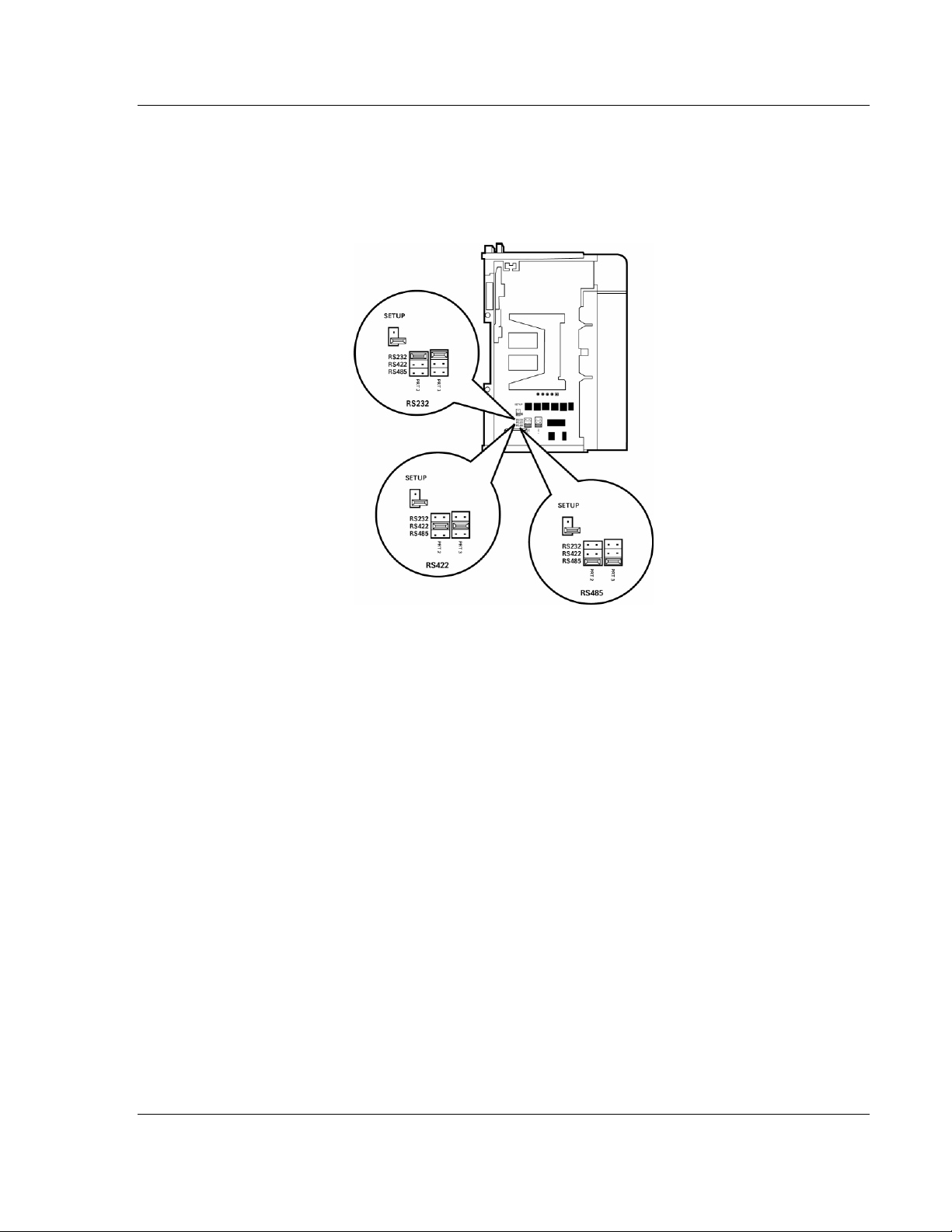
1.3 Setting Jumpers
When the module is manufactured, the port selection jumpers are set to RS-232.
To use RS-422 or RS-485, you must set the jumpers to the correct position. The
following diagram describes the jumper settings.
The Setup Jumper acts as "write protection" for the module's flash memory. In
"write protected" mode, the Setup pins are not connected, and the module's
firmware cannot be overwritten. Do not jumper the Setup pins together unless
you are directed to do so by ProSoft Technical Support.
ProSoft Technology, Inc. Page 11 of 131
November 3, 2008
Page 12
MVI69-103M ♦ CompactLogix or MicroLogix Platform Start Here
IEC 60870-5-103 Master Communication Module
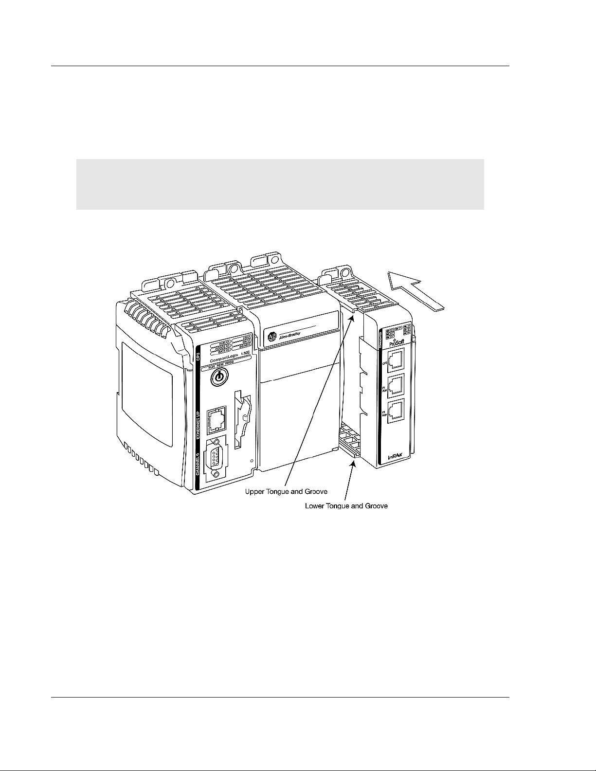
1.4 Install the Module in the Rack
This section describes how to install the module into a CompactLogix or
MicroLogix rack
Before you attempt to install the module, make sure that the bus lever of the
adjacent module is in the unlocked (fully right) position.
Warning: This module is not hot-swappable! Always remove power from the rack before
inserting or removing this module, or damage may result to the module, the processor, or other
connected devices.
1 Align the module using the upper and lower tongue-and-groove slots with the
adjacent module and slide forward in the direction of the arrow.
2 Move the module back along the tongue-and-groove slots until the bus
connectors on the MVI69 module and the adjacent module line up with each
other.
Page 12 of 131 ProSoft Technology, Inc.
November 3, 2008
Page 13
Start Here MVI69-103M ♦ CompactLogix or MicroLogix Platform
IEC 60870-5-103 Master Communication Module
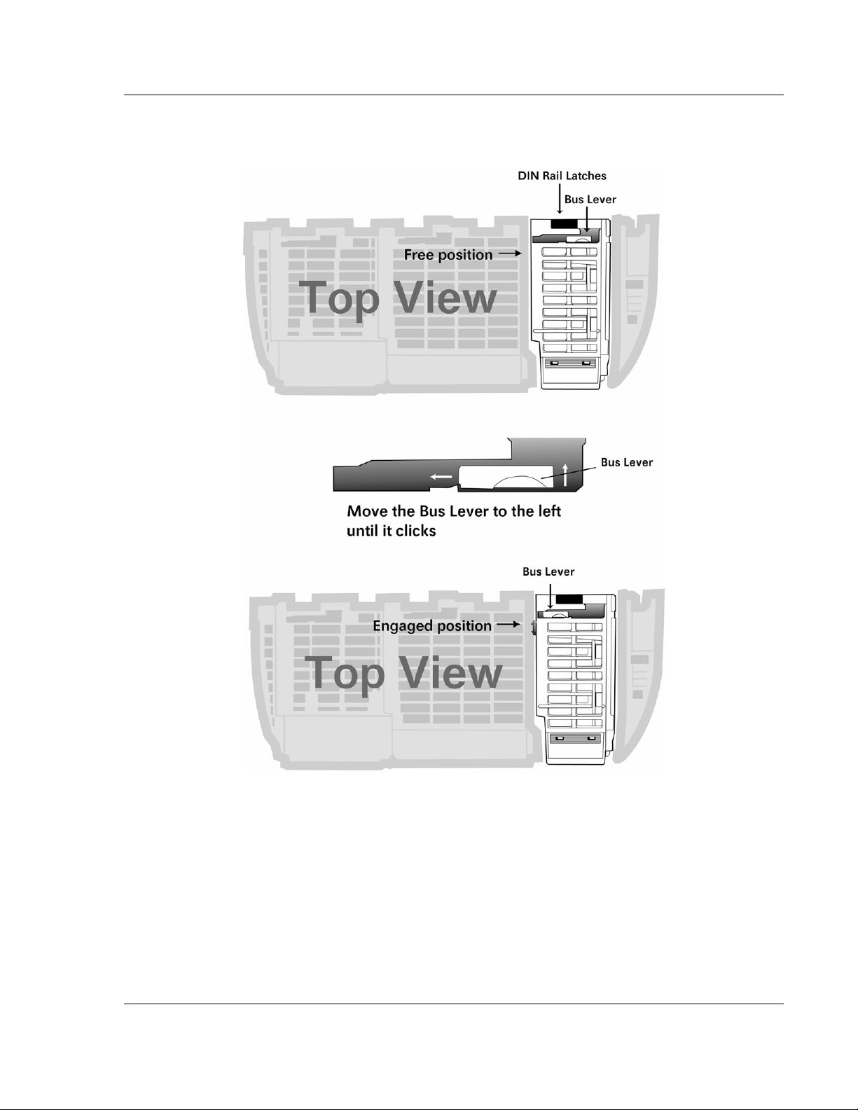
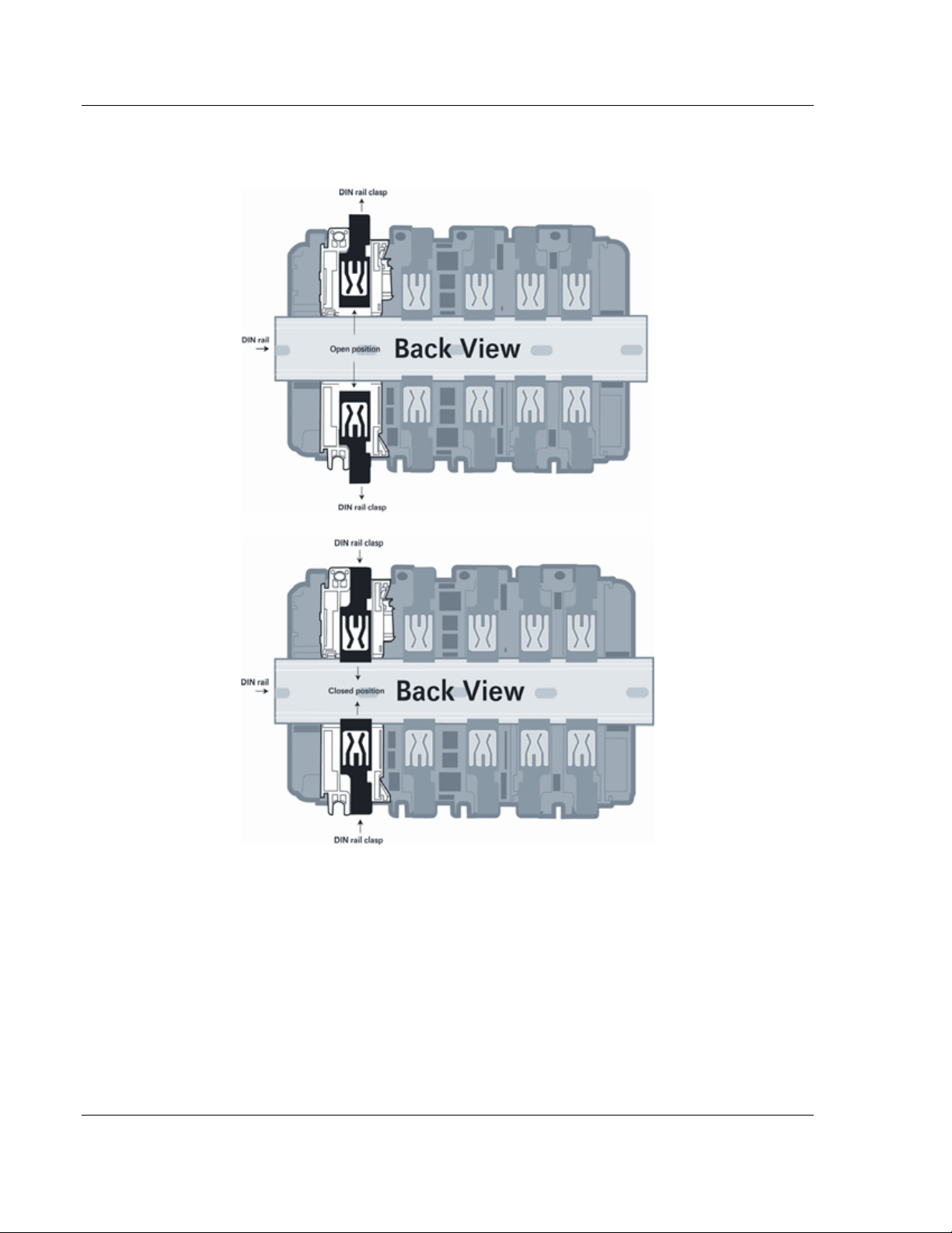
3 Push the module's bus lever back slightly to clear the positioning tab and
move it firmly to the left until it clicks. Ensure that it is locked firmly in place.
4 Close all DIN rail latches.
ProSoft Technology, Inc. Page 13 of 131
November 3, 2008
Page 14
MVI69-103M ♦ CompactLogix or MicroLogix Platform Start Here
IEC 60870-5-103 Master Communication Module
5 Press the DIN rail mounting area of the controller against the DIN rail. The
latches will momentarily open and lock into place.
Page 14 of 131 ProSoft Technology, Inc.
November 3, 2008
Page 15
Start Here MVI69-103M ♦ CompactLogix or MicroLogix Platform
IEC 60870-5-103 Master Communication Module
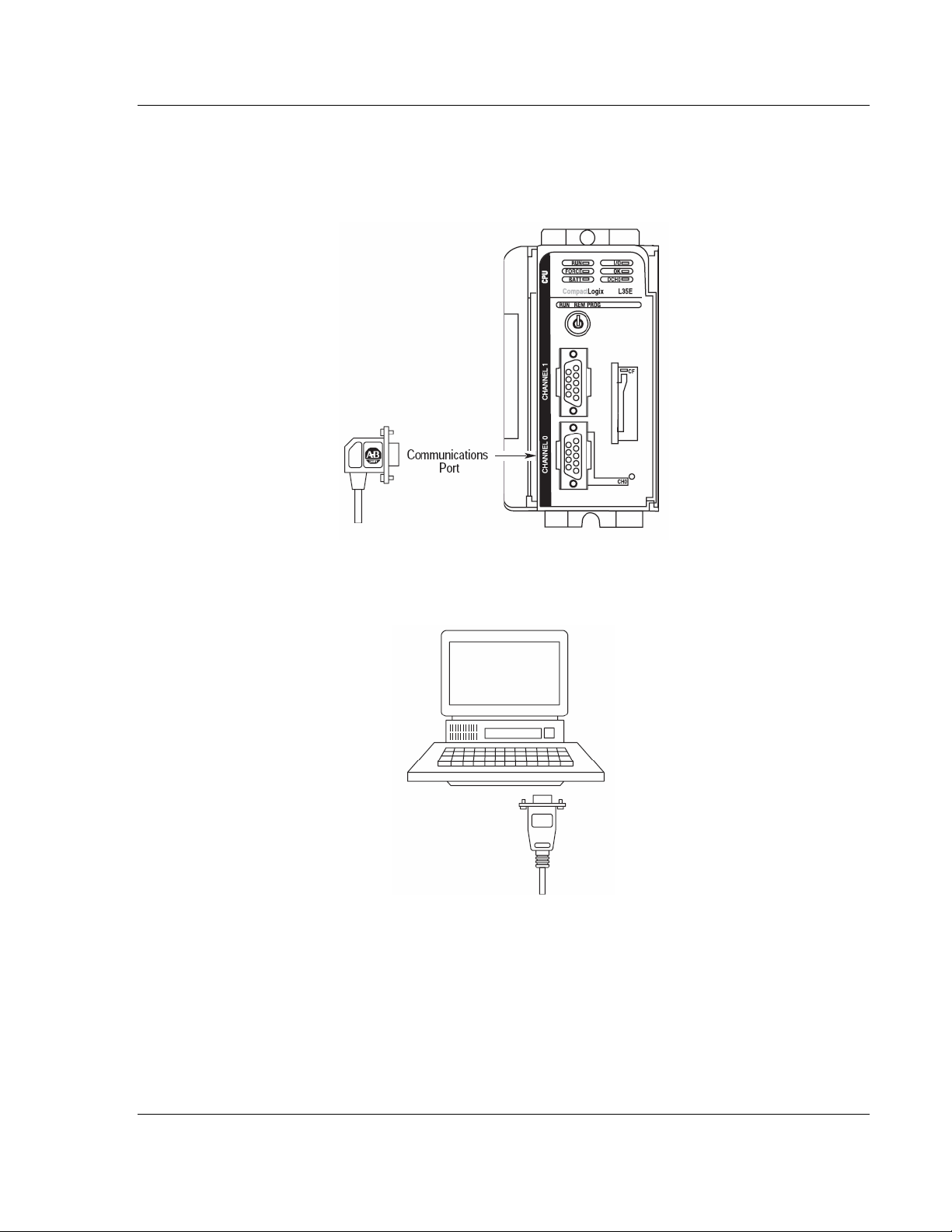
1.5 Connect your PC to the Processor
1 Connect the right-angle connector end of the cable to your controller at the
communications port.
2 Connect the straight connector end of the cable to the serial port on your
computer.
ProSoft Technology, Inc. Page 15 of 131
November 3, 2008
Page 16
MVI69-103M ♦ CompactLogix or MicroLogix Platform Start Here
IEC 60870-5-103 Master Communication Module
1.6 Download the Sample Program to the Processor
Important: For most applications, the sample program will work without modification.
Note: The key switch on the front of the CompactLogix processor must be in the REM position.
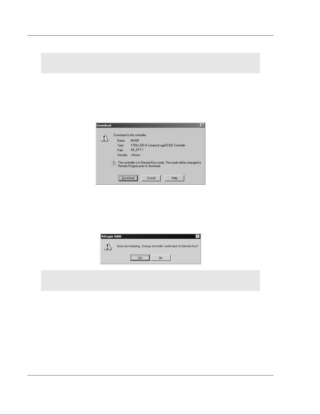
1 If you are not already online to the processor, open the Communications
menu, and then choose Download. RSLogix will establish communication
with the processor.
2 When communication is established, RSLogix will open a confirmation dialog
box. Click the Download button to transfer the sample program to the
processor.
3 RSLogix will compile the program and transfer it to the processor. This
process may take a few minutes.
4 When the download is complete, RSLogix will open another confirmation
dialog box. Click OK to switch the processor from Program mode to Run
mode.
Note: If you receive an error message during these steps, refer to your RSLogix documentation to
interpret and correct the error.
Page 16 of 131 ProSoft Technology, Inc.
November 3, 2008
Page 17
Start Here MVI69-103M ♦ CompactLogix or MicroLogix Platform
IEC 60870-5-103 Master Communication Module
1.6.1 Configuring RSLinx
If RSLogix is unable to establish communication with the processor, follow these steps:
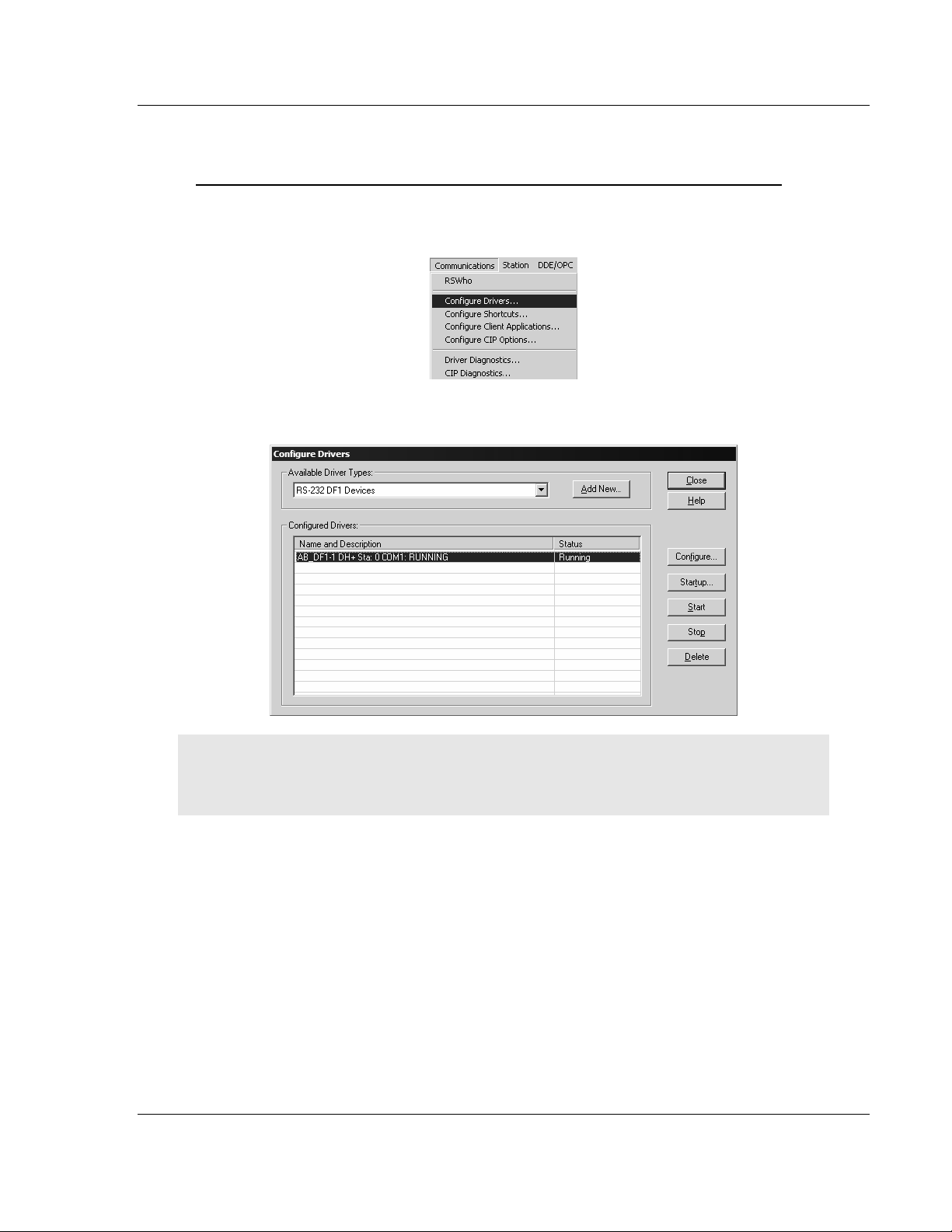
1 Open RSLinx.
2 Open the Communications menu, and choose Configure Drivers.
This action opens the Configure Drivers dialog box.
Note: If the list of configured drivers is blank, you must first choose and configure a driver from the
Available Driver Types list. The recommended driver type to choose for serial communication with
the processor is "RS-232 DF1 Devices".
ProSoft Technology, Inc. Page 17 of 131
November 3, 2008
Page 18
MVI69-103M ♦ CompactLogix or MicroLogix Platform Start Here
IEC 60870-5-103 Master Communication Module
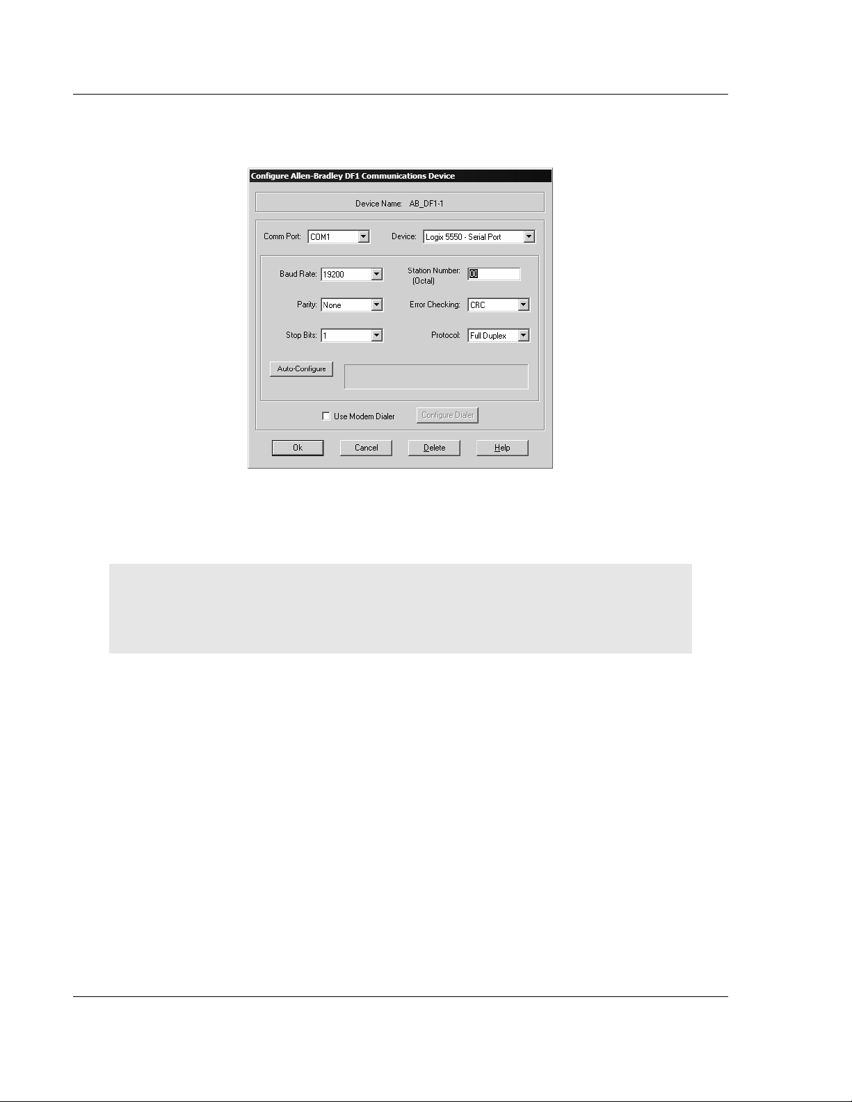
3 Click to select the driver, and then click Configure. This action opens the
Configure Allen-Bradley DF1 Communications Device dialog box.
4 Click the Auto-Configure button. RSLinx will attempt to configure your serial
port to work with the selected driver.
5 When you see the message "Auto Configuration Successful", click the OK
button to dismiss the dialog box.
Note: If the auto-configuration procedure fails, verify that the cables are connected correctly
between the processor and the serial port on your computer, and then try again. If you are still
unable to auto-configure the port, refer to your RSLinx documentation for further troubleshooting
steps.
Page 18 of 131 ProSoft Technology, Inc.
November 3, 2008
Page 19
Start Here MVI69-103M ♦ CompactLogix or MicroLogix Platform
IEC 60870-5-103 Master Communication Module
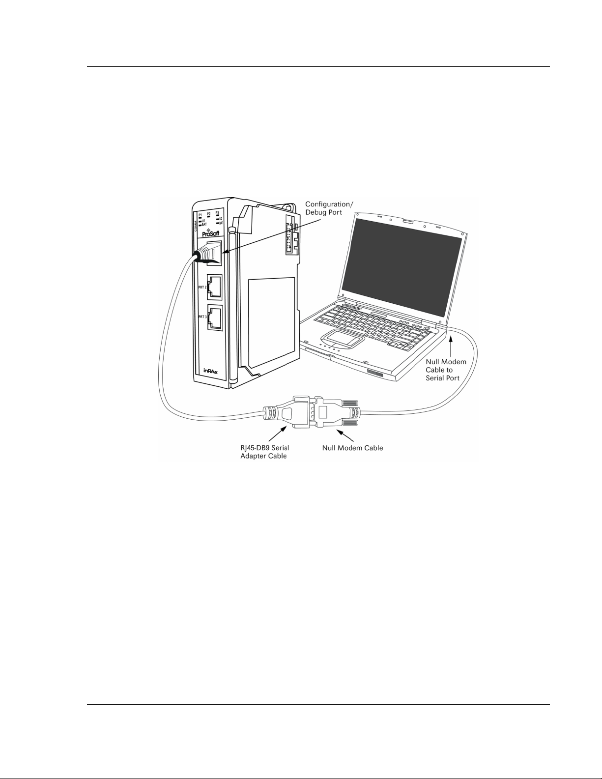
1.7 Connect your PC to the Module
With the module securely mounted, connect your PC to the Configuration/Debug
port using an RJ45-DB-9 Serial Adapter Cable and a Null Modem Cable.
1 Attach both cables as shown.
2 Insert the RJ45 cable connector into the Configuration/Debug port of the
module.
3 Attach the other end to the serial port on your PC or laptop.
ProSoft Technology, Inc. Page 19 of 131
November 3, 2008
Page 20

MVI69-103M ♦ CompactLogix or MicroLogix Platform Start Here
IEC 60870-5-103 Master Communication Module
Page 20 of 131 ProSoft Technology, Inc.
November 3, 2008
Page 21
Configuring the MVI69-103M Module MVI69-103M ♦ CompactLogix or MicroLogix Platform
IEC 60870-5-103 Master Communication Module
2 Configuring the MVI69-103M Module
In This Chapter
Configuration File ..................................................................................21
[Backplane Configuration] .....................................................................23
[IEC-870-5-103 Master].........................................................................24
[IEC-870-5-103 Master Port x]...............................................................24
[IEC-101 Master Session x]...................................................................25
[IEC-103 Master Session x Sector y].....................................................28
[IEC-103 Master Commands]................................................................29
Uploading and Downloading the Configuration File...............................31
2.1 Configuration File
The MVI69-103M module stores its configuration in a text file called
IEC103M.CFG, located in the module's flash memory. When the module starts
up, it reads the configuration file and uses the information to control how the 103
protocol interacts with the module's application port(s).
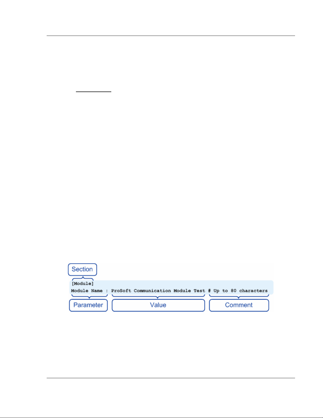
The configuration file is arranged in Sections, with a heading in [ ] characters at
the beginning of each section. Each Section contains a list of Parameters and
Values, followed by an optional Comment that explains the parameter.
The following illustration shows an example of a Section, a Parameter, a Value,
and a Comment.
The Parameter must be followed by a [:] (colon) character. The text following the
[:] is a Value.
The module ignores "comment" text following the [#] character. Use comments to
document your configuration settings.
You can get a sample configuration file for the module in the following places:
Copy (page 31) the IEC103M.CFG from the module's flash memory to your
PC
ProSoft Technology, Inc. Page 21 of 131
November 3, 2008
Page 22
MVI69-103M ♦ CompactLogix or MicroLogix Platform Configuring the MVI69-103M Module
IEC 60870-5-103 Master Communication Module
Copy the IEC103M.CFG from the ProSoft Solutions CD-ROM supplied with
the module
Download the IEC103M.CFG from the ProSoft Technology web site at
http://www.prosoft-technology.com
2.1.1 Editing the Configuration File
The IEC103M.CFG file is a plain ASCII text file. Use a text editor such as
Notepad.exe (included with Microsoft Windows) to open and edit the file.
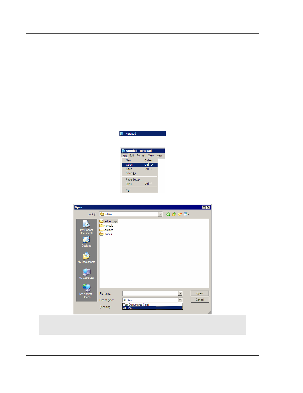
To open the configuration file in Notepad
1 Click the Start button, and then choose Programs
2 Expand the Programs menu, and then choose Accessories.
3 On the Accessories menu, choose Notepad.
4 In Notepad, open the File menu, and then choose Open
5 In the Open dialog box, select "All Files" in the Files of Type: dropdown list.
Tip: Sample configuration files are stored under the LadderLogic folder on the ProSoft Solutions
CD-ROM.
6 Navigate to the folder containing the configuration file, and then select the file
to edit.
7 Click Open to open the file.
Page 22 of 131 ProSoft Technology, Inc.
November 3, 2008
Page 23

Configuring the MVI69-103M Module MVI69-103M ♦ CompactLogix or MicroLogix Platform
IEC 60870-5-103 Master Communication Module
8 When you have finished editing, save the file and close Notepad.
Important: Changes to the configuration file will not take effect until you download the file to the
module, and then reboot the module.
2.2 [Backplane Configuration]
2.2.1 Module Name
0 to 80 characters
This parameter assigns a name to the module that can be viewed using the
configuration/debug port. Use this parameter to identify the module and the
configuration file.
2.2.2 Read Register Start
Range 0 to 3999
This parameter specifies the starting register in the module where data will be
transferred from the module to the processor. Valid range for this parameter is 0
to 3999.
2.2.3 Read Register Count
Range 0 to 3999
This parameter specifies the number of registers to be transferred from the
module to the processor. Valid entry for this parameter is 0 to 3999.
2.2.4 Write Register Start
0 to 3999
This parameter specifies the starting register in the module where the data will be
transferred from the processor to the module.
2.2.5 Write Register Count
Range 0 to 3999
This parameter specifies the number of registers to be transferred from the
module to the processor. Valid entry for this parameter is 0 to 3999
2.2.6 Failure Flag Count
0 through 65535
This parameter specifies the number of successive transfer errors that must
occur before the communication ports are shut down. If the parameter is set to 0,
the communication ports will continue to operate under all conditions. If the value
is set larger than 0 (1 to 65535), communications will cease if the specified
number of failures occur.
ProSoft Technology, Inc. Page 23 of 131
November 3, 2008
Page 24

MVI69-103M ♦ CompactLogix or MicroLogix Platform Configuring the MVI69-103M Module
IEC 60870-5-103 Master Communication Module
2.2.7 Pass-Through Events
Y or N (N = Default)
This parameter specifies if event messages received on the master ports will be
passed to the processor. If the parameter is set to N, event messages will not be
passed to the processor. If the parameter is set to Y, the module will pass all
events received to the processor using block identifier 9903.
2.2.8 Block Transfer Size
60, 120 or 240
This read-only parameter specifies the number of words in each block transferred
between the module and processor. Valid values for this parameter are 60, 120
and 240.
2.3 [IEC-870-5-103 Master]
2.3.1 Session Count
1 to 16
This parameter specifies the maximum number of sessions to establish on the
module. This corresponds to the number of slaves to be interfaced with the
module. This value represents the total number of slaves on both ports
combined.
2.4 [IEC-870-5-103 Master Port x]
2.4.1 Baud Rate
Value for baud rate
This parameter specifies the baud rate to be used on the communication channel
(port). Two values are valid; 19200 or 9600.
2.4.2 Parity
N, O, E, M, or S
This parameter sets the parity to be used on the port. The values correspond to
the following settings: N=None, O=Odd, E=Even, M=Mark and S=Space.
Note: the specification only utilizes Even Parity.
2.4.3 RTS On
0 to 65535 milliseconds
This parameter sets the number of milliseconds to delay after RTS is asserted
before the data will be transmitted.
Page 24 of 131 ProSoft Technology, Inc.
November 3, 2008
Page 25

Configuring the MVI69-103M Module MVI69-103M ♦ CompactLogix or MicroLogix Platform
IEC 60870-5-103 Master Communication Module
2.4.4 RTS Off
0 to 65535 milliseconds
This parameter sets the number of milliseconds to delay after the last byte of
data is sent before the RTS modem signal will be set low.
2.4.5 Minimum Delay
1 to 65535
This parameter specifies the minimum number of milliseconds to delay before
sending the message (setting RTS high). This can be used when the serial
network requires time for units to turn off their transmitters.
2.4.6 Receive Timeout
1 to 65535
This value represents the number of milliseconds to wait on a port from the time
the first character is received until the last character in the longest message
received on the port. This parameter should be dependent on the baud rate. A
value of 2000 should work with most applications.
2.4.7 Single char ACK F0, 1, or 3
Yes or No
This parameter specifies if the signal E5 character will be used for ACK
messages.
2.5 [IEC-101 Master Session x]
This section is used to define session x which runs on Port x. The session
sections of the configuration file are determined by the number of sessions set in
the configuration file. The sessions are referenced by a zero based index value.
For example, if the module is configured for four sessions, the configuration file
should contain sections for sessions 0 to 3 (that is, [IEC-101 Master Session 0] to
[IEC-101 Master Session 3]. Each of these sections will define the characteristics
of the specific controlled device to be interfaced.
2.5.1 Communication Port
0 or 1
This parameter sets the port to which the controlled device is connected. On this
module, values of 0 and 1 are permitted.
2.5.2 Sector Count
1 to 3
This parameter sets the number of sectors contained in this controlled device.
This version of the application from 1 to 3 sectors (separate databases) for each
session.
ProSoft Technology, Inc. Page 25 of 131
November 3, 2008
Page 26

MVI69-103M ♦ CompactLogix or MicroLogix Platform Configuring the MVI69-103M Module
IEC 60870-5-103 Master Communication Module
2.5.3 Data Link Address
0 to 254
This parameter uniquely defines the data link address for this unit on the
communication channel. The ranges of values are from 0 to 254. Address 255 is
the broadcast address.
2.5.4 Failure Delay
0 to 2000
This parameter sets the minimum number of seconds to delay before polling this
session when it is not online. This parameter is only used in unbalanced mode.
2.5.5 Confirm Timeout
0 to 2^32-1
This parameter sets the number of milliseconds to wait for a confirm response
from the controlled device.
2.5.6 Retry Count
0 to 255
This parameter sets the number of retries to be performed on the controlled
device when a communication occurs.
2.5.7 C1/C2 Poll Count Pend
0 to 65535
This parameter sets the maximum number of class 1 and class 2 polls performed
on this session before trying the next session. This parameter prevents a session
from monopolizing the communication port.
2.5.8 Class 1 Polls
0 to 100
This parameter sets the maximum number of class 1 polls performed on this
session before switching to another session. This parameter prevents a session
from monopolizing the communication port.
2.5.9 Class 1 Pend Delay
0 to 2^32-1
This parameter sets the minimum number of milliseconds to delay between class
1 polls for pending data.
Page 26 of 131 ProSoft Technology, Inc.
November 3, 2008
Page 27

Configuring the MVI69-103M Module MVI69-103M ♦ CompactLogix or MicroLogix Platform
IEC 60870-5-103 Master Communication Module
2.5.10 Class 2 Pend Delay
0 to 2^32-1
This parameter sets the minimum number of milliseconds to delay between class
2 polls for pending data.
2.5.11 Class 1 Poll Delay
0 to 2^32-1
This parameter sets the minimum number of milliseconds to delay between each
class 1 poll.
2.5.12 Class 2 Poll Delay
0 to 2^32-1
This parameter sets the minimum number of milliseconds to delay between each
class 2 poll.
2.5.13 Auto Clock Req Mode
0=Sync Only, 1=Load delay/sync, 2=Acquire delay/load delay/sync
This parameter specifies the method used to perform automatic clock
synchronization. 0 performs a synchronization without delay, 1 performs
synchronization using the fixed Propagation Delay and 2 computes the delay and
use this value when synchronization takes place.
2.5.14 Propagation Delay
0 to 65535
This parameter sets the fixed propagation delay to be utilized if the Auto Clock
Req Mode parameter is set to a value of 1.
2.5.15 Response Timeout
0 to 2^32-1 milliseconds
This parameter sets the maximum number of milliseconds to wait for a
confirmation from the controlled station to a request from this module.
2.5.16 ACTTERM with setpoint
Yes or No
This parameter determines if an ACTTERM will be sent. If the parameter is set to
Yes, then setpoint commands will issue an ACTTERM when the command is
complete. If the parameter is set to No, ACTCON is the last response to a
setpoint command.
ProSoft Technology, Inc. Page 27 of 131
November 3, 2008
Page 28

MVI69-103M ♦ CompactLogix or MicroLogix Platform Configuring the MVI69-103M Module
IEC 60870-5-103 Master Communication Module
2.6 [IEC-103 Master Session x Sector y]
Within each session definition, is a parameter that specifies the number of
sectors for the session. For each sector defined for a session, there must exist a
[IEC-103 Master Session x Sector y] section. Where the x value represents the
session index and the y value represents sector index. For example if session 0
contains 1 sector, there must be a section with the following name in the
configuration file: [IEC-103 Master Session 0 Sector 0].
2.6.1 Common ASDU Address
0 to 255
This parameter sets the common ASDU address to association with this sector of
the specified session. This parameter is usually set the same as the data link
address when only one sector is used.
2.6.2 Online Time Sync.
Yes or No
This parameter specifies if the sector in the controlled device will be sent a time
synchronization command when the unit is first recognized as being online. This
should only be used for devices that do not send an EOI message after
initializing.
2.6.3 Online General Int
Yes or No
This parameter specifies if the sector in the controlled device will be sent a
general interrogation command when the unit is first recognized as being online.
This should only be used for devices that do not send an EOI message after
initializing.
2.6.4 EOI Time Sync.
Yes or No
This parameter specifies if the sector in the controlled device will be sent a time
synchronization command after this module received an EOI message from the
controlled unit.
2.6.5 EOI General Int
Yes or No
This parameter specifies if the sector in the controlled device will be sent a
general interrogation command after this module received an EOI message from
the controlled unit.
Page 28 of 131 ProSoft Technology, Inc.
November 3, 2008
Page 29

Configuring the MVI69-103M Module MVI69-103M ♦ CompactLogix or MicroLogix Platform
IEC 60870-5-103 Master Communication Module
2.7 [IEC-103 Master Commands]
This section can contain up to 1000 user defined commands to be executed by
the module and sent to the controlled devices. There is no need to place Class 1
or Class 2 polls in the this list for the controlled devices as the master driver for
each port will execute these automatically when the port is idle. In order for the
port to be idle, make sure that there is idle time available, and that the
commands do not constantly utilize the ports. The command list section starts
with a reserved label START and ends with the label END. Each row in the file
corresponds to an individual command with the first character position in each
row left blank (white space).
As an alternative to using a command list, blocks with an identification code of
9901 can be used to issue commands from the ladder logic.
2.7.1 Enable Code
0 = Disabled
1 = Enabled with Poll Interval (seconds) utilized
2 = Conditional (executed when point in database changes)
This field defines whether or not the command is to be executed and under what
conditions. If the parameter is set to 0, the command is disabled and will not be
executed in the normal polling sequence. The command can be executed under
the control of the PLC processor through the use of a Command Control block.
Setting the parameter to a value of 1 for the command causes the command to
be executed each scan of the command list if the Poll Interval Time is set to zero.
If the Poll Interval time is set, the command will be executed, when the interval
timer expires. If the parameter is set to 2, the command will execute only if the
internal data associated with the command changes. This value is valid only for
write commands.
2.7.2 Database Index
Database Index is the location in the module's database to use as the source for
the data in the command. The data type field determines the meaning of the
index as follows:
Type Description DB Index type
6 Clock synchronization NA
7 General interrogation NA
20 General Command Bit address
2.7.3 Poll Interval
This parameter specifies the minimum frequency at which the module should
execute the command. The value is entered in units of seconds. For example, to
execute a command every 10 seconds, enter a value of 10 in the field. A value of
0 for the parameter implies that the command should be executed every scan of
the list.
ProSoft Technology, Inc. Page 29 of 131
November 3, 2008
Page 30

MVI69-103M ♦ CompactLogix or MicroLogix Platform Configuring the MVI69-103M Module
IEC 60870-5-103 Master Communication Module
2.7.4 Session Index
Session Index represents the session index in the module to associate with the
command. This index is set when the session is read in from this file. The range
of values for this field is 0 to 31.
2.7.5 Sector Index
Sector Index represents the sector index for the specific session. The range of
values for this field is 0 to 2.
2.7.6 Data Type
Data type file represents the ASDU type as follows:
6 = Time synchronization
7 = General Interrogation
20 = General Command
2.7.7 Function Code
Code Definition
128 Distance protection
160 Overcurrent protection
176 Transformer differential protection
192 Line Differential protection
255 Global function type
2.7.8 Point Index
Point Index field specifies the address in the remote slave device of the point to
interact with.
Page 30 of 131 ProSoft Technology, Inc.
November 3, 2008
Page 31

Configuring the MVI69-103M Module MVI69-103M ♦ CompactLogix or MicroLogix Platform
IEC 60870-5-103 Master Communication Module
2.8 Uploading and Downloading the Configuration File
ProSoft modules are shipped with a pre-loaded configuration file. In order to edit
this file, you must transfer the file from the module to your PC. After editing, you
must transfer the file back to the module.
This section describes these procedures.
Important: The illustrations of configuration/debug menus in this section are intended as a general
guide, and may not exactly match the configuration/debug menus in your own module. For specific
information about the configuration/debug menus in your module, refer to The Configuration/Debug
Menu (page 51).
2.8.1 Required Hardware
You can connect directly from your computer's serial port to the serial port on the
module to view configuration information, perform maintenance, and send
(upload) or receive (download) configuration files.
ProSoft Technology recommends the following minimum hardware to connect
your computer to the module:
80486 based processor (Pentium preferred)
1 megabyte of memory
At least one UART hardware-based serial communications port available.
USB-based virtual UART systems (USB to serial port adapters) often do not
function reliably, especially during binary file transfers, such as when
uploading/downloading configuration files or module firmware upgrades.
A null modem serial cable.
2.8.2 Required Software
In order to send and receive data over the serial port (COM port) on your
computer to the module, you must use a communication program (terminal
emulator).
A simple communication program called HyperTerminal is pre-installed with
recent versions of Microsoft Windows operating systems. If you are connecting
from a machine running DOS, you must obtain and install a compatible
communication program. The following table lists communication programs that
have been tested by ProSoft Technology.
DOS ProComm, as well as several other terminal emulation programs
Windows 3.1 Terminal
Windows 95/98 HyperTerminal
Windows NT/2000/XP HyperTerminal
The module uses the Zmodem file transfer protocol to send (upload) and receive
(download) configuration files from your module. If you use a communication
program that is not on the list above, please be sure that it supports Zmodem file
transfers.
ProSoft Technology, Inc. Page 31 of 131
November 3, 2008
Page 32

MVI69-103M ♦ CompactLogix or MicroLogix Platform Configuring the MVI69-103M Module
IEC 60870-5-103 Master Communication Module
2.8.3 Transferring the Configuration File to Your PC
1 Connect your PC to the Configuration/Debug port of the module using a
terminal program such as HyperTerminal. Press [?] to display the main
menu.
2 From the Transfer menu in HyperTerminal, select Receive File.
3 In the Receive File dialog box, browse to the location on your PC where the
configuration file should be stored, and select Zmodem (or Zmodem with
Crash Recovery) as the receiving protocol.
When you have completed your selections, click Close.
Page 32 of 131 ProSoft Technology, Inc.
November 3, 2008
Page 33
Configuring the MVI69-103M Module MVI69-103M ♦ CompactLogix or MicroLogix Platform
IEC 60870-5-103 Master Communication Module
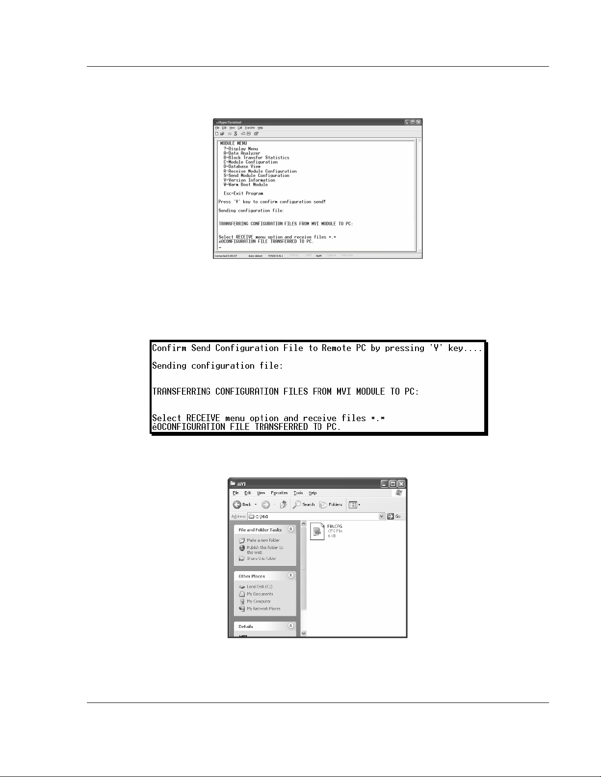
4 Press [S] (Send Module Configuration), and then press [Y] to confirm the
transfer.
The file transfer will then begin automatically, using the protocol and location
you specified in Step 3.
When the configuration file has been transferred to your PC, the dialog box
will indicate that the transfer is complete.
The configuration file is now on your PC at the location you specified.
5 You can now open and edit the file in a text editor such as Notepad. (page
22) When you have finished editing the file, save it and close Notepad.
ProSoft Technology, Inc. Page 33 of 131
November 3, 2008
Page 34

MVI69-103M ♦ CompactLogix or MicroLogix Platform Configuring the MVI69-103M Module
IEC 60870-5-103 Master Communication Module
2.8.4 Transferring the Configuration File to the Module
Perform the following steps to transfer a configuration file from your PC to the
module.
1 Connect your PC to the Configuration/Debug port of the module using a
terminal program such as HyperTerminal. Press [?] to display the main
menu.
2 Press [R] (Receive Module Configuration). The message "Press Y key to
confirm configuration receive!" is displayed at the bottom of the screen.
3 Press [Y]. The screen now indicates that the PC is ready to send.
Page 34 of 131 ProSoft Technology, Inc.
November 3, 2008
Page 35

Configuring the MVI69-103M Module MVI69-103M ♦ CompactLogix or MicroLogix Platform
IEC 60870-5-103 Master Communication Module
4 From the Transfer menu in HyperTerminal, select Send File.
The Send File dialog appears.
5 Use the Browse button to locate the configuration file your computer.
Note: This procedure assumes that you are uploading a newly edited configuration file from your
PC to the module. However, configuration files are also available on the ProSoft CD as well as the
ProSoft Technology web site.
6 Select Zmodem as the protocol.
ProSoft Technology, Inc. Page 35 of 131
November 3, 2008
Page 36

MVI69-103M ♦ CompactLogix or MicroLogix Platform Configuring the MVI69-103M Module
IEC 60870-5-103 Master Communication Module
7 Click the Send button. This action opens the Zmodem File Send dialog box.
When the upload is complete, the screen indicates that the module has
reloaded program values and displays information about the module.
8 Your module now contains the new configuration.
Page 36 of 131 ProSoft Technology, Inc.
November 3, 2008
Page 37

Ladder Logic MVI69-103M ♦ CompactLogix or MicroLogix Platform
IEC 60870-5-103 Master Communication Module
3 Ladder Logic
In This Chapter
Module Data..........................................................................................37
Adding the Module to an Existing CompactLogix Project......................45
Adding the Module to an Existing MicroLogix Project............................49
Ladder logic is required for application of the MVI69-103M module. Tasks that
must be handled by the ladder logic are module data transfer, special block
handling and status data receipt. Additionally, a power-up handler may be
needed to handle the initialization of the module's data and to clear any
processor fault conditions.
The sample ladder logic, on the ProSoft Solutions CD-ROM, is extensively
commented, to provide information on the purpose and function of each rung. For
most applications, the sample ladder will work without modification.
3.1 Module Data
This section describes the controller tags that are defined in the example logic to
interface with the module. The user can extend these tags to meet the
specifications required for their application.
3.1.1 Module Status Data and Variables (MVI69103M_ModuleDef)
All status and variable data related to the MVI69-103M is stored in a user-defined
data type. An instance of the data type is required before the module can be
used. This is done by declaring a variable of the data type in the Controller Tags
Edit Tags dialog box. The structure of the object is displayed in the following
example:
Tag Type Data Type Description
DATA MV69103M_DATA Stores data point values
CONTROL MVI69103M_CONTROL Optional block handling
STATUS MVI69103M_STATUS Stores module status
UTIL MVI69103M_UTIL
This object contains objects that define variables to be used with the module and
status data related to the module. Each of these object types is discussed in the
following topics of the document.
Stores convenience variables for ladder logic
usage
ProSoft Technology, Inc. Page 37 of 131
November 3, 2008
Page 38

MVI69-103M ♦ CompactLogix or MicroLogix Platform Ladder Logic
IEC 60870-5-103 Master Communication Module
Status Object (MVI69103M_Status)
This object stores the status data of the module. The MVI69103M_Status object
shown below is updated each time a read block is received by the processor.
Use this data to monitor the state of the module at a "real-time rate".
Data Type Description
Scan_Cnt Program Scan Counter
Product_Name Product Code
Revision_Level Revision
Operating_System Operating System revision
Run_Number Run number
Block_Read_Count Number of block read transfers
Block_Write_Count Number of block write transfer s
Block_Parse_Count Number of blocks parsed by module
Block_Error Number of block errors
Event_Count Number of event messages in buffer
Event_Overflow Flag to indicate event message buffer overflow (1=overflow)
SessionCount Number of sessions configured
CurentCommand Index of command executing
CommanddBusy Command busy flag
CommandMax Maximum number of commands configured
CommandDelay Command delay counter
CommandQueue Command Queue Flag
CommandQueueCount Number of commands in command queue
Online Online status bits for each session
ChStat Channel Status Data
BlockTransferSize 60, 120 or 240
Within the MVI69103M_Statust objects are objects containing the status
information for each application port (MVI69103M_ChannelStatus). Refer to
103M Status Data Area for a complete listing of the data stored in this object.
Channel Status Object (MVI69103M_ChannelStatus)
The MVI69103M_ChannelStatus object holds the status data related to a single
IEC 60870-5-103 Master port. The structure of this object is shown in the
following example:
Data Type Description
State State machine value
CmdReq Number of command requests
CmdResp Number of command responses
CmdErr Number of command errors
Req Number of request messages
Resp Number of responses
ErrSent Number of errors sent
ErrRec Number of errors received
Page 38 of 131 ProSoft Technology, Inc.
November 3, 2008
Page 39

Ladder Logic MVI69-103M ♦ CompactLogix or MicroLogix Platform
IEC 60870-5-103 Master Communication Module
Data Type Description
CfgErr Configuration Error Word for channel
CurErr Current error code for channel
LastErr Last error for channel
This information is passed to the controller from the module with each normal
read block image.
Configuration/Error Status Flags (CfgErr)
The CfgErr word member of the MVI69103M_ChannelStatus reports
configuration errors for the respective server. If the module is not functioning as
expected, inspect the value presented in this object. If a configuration error
exists, the associated bit will be set. A value of zero for the bit indicates the
configuration value is valid. This does not guarantee that the module is
configured correctly for your application. The bits used by this member are
shown in the following table.
Bit Code Description
0 0x0001 Invalid baud rate selected
1 0x0002 Invalid parity selected
2 0x0004 Received timeout set to 0
3 0x0008 Invalid Port selected for a session
4 0x0010 Invalid sector count for session
5 0x0020 Could not allocate memory for sector of a session.
6 0x0040
7 0x0080 Invalid failure delay or confirm timeout for session.
8 0x0100
9 0x0200
10 0x0400
11 0x0800
12 0x1000
13 0x2000
14 0x4000
15 0x8000
3.1.2 Backplane Object (MVI69103M_UTIL)
The MVI69103M_UTIL object stores all the variables required for the data
transfer operation between the module and the controller. The LastRead data
member is used as the handshaking byte to indicate the arrival of new data from
the module. The structure of this object is shown in the following illustration:
Data Type Description
Warmboot Requests warmboot of the module
ColdBoot Requests coldboot of the module
BPLastRead Index of last read
BPLastWrite Index of last write
BlockIndex Computed block offset for data table
ProSoft Technology, Inc. Page 39 of 131
November 3, 2008
Page 40

MVI69-103M ♦ CompactLogix or MicroLogix Platform Ladder Logic
IEC 60870-5-103 Master Communication Module
Data Type Description
BootTimer Used to clear output block ID after power up
LoopIndex Used as index during Loops
TempByte Used for INT/SINT conversion
TempINT Used for SINT/INT Conversion
TempDINT Used for INT/SINT conversion
The other members of the object are be utilized in the ladder logic to assist in the
data transfer operation.
3.1.3 Data Object (MV69103M_DATA)
Data for the module is stored in two controller tags for the example ladder logic.
The read data (data transferred from the module to the processor) is stored in the
controller tag MVI69103M.DATA.ReadData[ ]. The write data (data transferred
from the processor to the module) is stored in the controller tag
MVI69103M.DATA.WriteData[ ]. Separate tags can be constructed for each data
type utilized by the controlled devices and for each device.
3.1.4 User Command Data Object (MVI69103M_UserCommand)
User Command is an optional feature that allows the processor to dynamically
build commands, instead of using the configured commands from the
configuration file.
In order to support the user command control of the module, refer to
MVI69103M.CONTROL.UserCommand.Activate to trigger the block. The tag
MVI69103M.CONTROL.UserCommand.Count sets the number of commands to
be sent (maximum of 5 per block). Use the tag
MVI69103M.CONTROL.UserCommand.UserCommand to set the commands.
The structure of this object is shown in the following figure:
Data Type Description
DBIndex Address in module's database to associate with command
Session Session Index
Sector Sector Index
DataType ASDU data type for command
FunctionCode Function code
InformationNumber Information object address of the point
OverrideFlag Override flag used with ASDU 20 (0=use db value, 1=use override)
OverrideValue Override value to use if override flag set
Refer to the Command List section of this document for the definition of each of
the parameters. This option permits execution of user-generated commands from
the ladder logic directly to controlled devices. This feature is especially important
in generating general commands (ASDU 20 object) request.
Page 40 of 131 ProSoft Technology, Inc.
November 3, 2008
Page 41
Ladder Logic MVI69-103M ♦ CompactLogix or MicroLogix Platform
IEC 60870-5-103 Master Communication Module
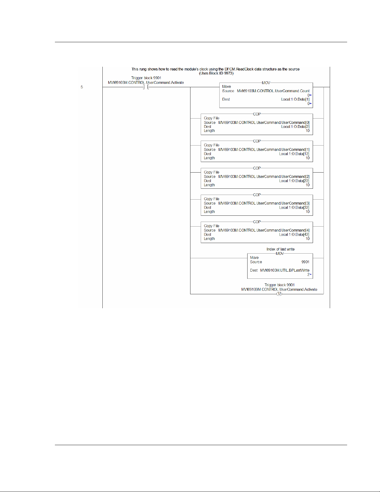
Example ladder logic to use this feature is shown in the following rung:
ProSoft Technology, Inc. Page 41 of 131
November 3, 2008
Page 42

MVI69-103M ♦ CompactLogix or MicroLogix Platform Ladder Logic
IEC 60870-5-103 Master Communication Module
When the command bit (MVI69103M.CONTROL.UserCommand.Activate[0]) is
set, the module will build a block 9901 with the command contained in the first
command of the MVI69103M.CONTROL.UserCommand.UserCommand[ ]. The
module receives this block and builds and sends the command to the specified
control device. The data for the command element in the
MVI69103M.CONTROL.UserCommand.UserCommand array is shown in the
following figure:
3.1.5 Command Control Data Object (MVI69103M_UserCommand)
The following rung displays ladder logic to build a 9902 block to place commands
2 and 3 of the user command list configured in the module's command queue:
Page 42 of 131 ProSoft Technology, Inc.
November 3, 2008
Page 43

Ladder Logic MVI69-103M ♦ CompactLogix or MicroLogix Platform
IEC 60870-5-103 Master Communication Module
When the command bit (MVI69103M.CONTROL.UserCommand.Activate) is set,
the module will build the block 9902 in the output image. The module will receive
the new block and place the commands into the command queue for execution.
3.1.6 Event Message Data Object (MVI69103M_Event)
The module can be configured to pass event messages received from the
controlled devices to the processor. Refer to the Pass-Through Events (page 24)
parameter for further information about this feature. The module sends this
information to the processor in read blocks with identification codes of 9903. The
example ladder logic has a data structure that conforms to the data structure sent
for each element by the module. The following figure displays the object:
Data Type Description
Session Session values
Sector Sector values
ASDU_Type ASDU type for event message
PointIndex Point index
Function Function index
FaultNumber Fault Number for event (ASDU type 2 and 4 only)
Milliseconds Milliseconds
Seconds Seconds
Minutes Minutes
Hour Hour
Invalid Valid time flag
DST Daylight savings time flag
RelativeTime Relative Time (ASDU type 2 and 4 only)
Value Value for event received (may want to set float type for ASDU 4)
ProSoft Technology, Inc. Page 43 of 131
November 3, 2008
Page 44
MVI69-103M ♦ CompactLogix or MicroLogix Platform Ladder Logic
IEC 60870-5-103 Master Communication Module
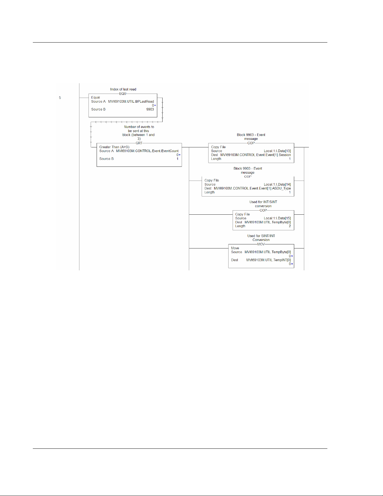
The example ladder logic defines a 5-element array of the MVI69103M_Event
objects to hold the data received in a single 9903 block. Ladder logic to handle a
9903 block is shown in the following figure:
This simple logic does not use the message count parameter in the block and will
not work for most applications. It is only provided as an example to display how
to move the 9903 data to a user controller tag. If the message pass-through
feature is utilized, more logic is required to store the messages received. This
feature is most commonly utilized to pass events from the controlled device to an
event logger connected to the processor.
3.1.7 Data Object (MVI69103M_Clock)
This type is used to copy the date and time information between the MVI and the
processor through optional block 9970 and 9971. Please refer to the sample
ladder logic (on the ProSoft Solutions CD) for further information about this
feature.
Page 44 of 131 ProSoft Technology, Inc.
November 3, 2008
Page 45

Ladder Logic MVI69-103M ♦ CompactLogix or MicroLogix Platform
IEC 60870-5-103 Master Communication Module
3.2 Adding the Module to an Existing CompactLogix Project
Important: The MVI69-103M module has a power supply distance rating of 2 (L43 and L45
installations on first 2 slots of 1769 bus)
If you are installing and configuring the module with a CompactLogix processor,
follow these steps. If you are using a MicroLogix processor, refer to the next
section.
1 Add the MVI69-103M module to the project. Right-click the mouse button
on the I/O Configuration option in the Controller Organization window to
display a pop-up menu. Select the New Module option from the I/O
Configuration menu.
ProSoft Technology, Inc. Page 45 of 131
November 3, 2008
Page 46

MVI69-103M ♦ CompactLogix or MicroLogix Platform Ladder Logic
IEC 60870-5-103 Master Communication Module
This action opens the following dialog box:
2 Select the 1769-Module (Generic 1769 Module) from the list and click OK.
3 Enter the Name, Description and Slot options for your application, using the
values in the illustration above. You must select the Comm Format as Data INT in the dialog box, otherwise the module will not communicate over the
backplane of the CompactLogix rack.
4 Configure the Connection Parameters to match to the Block Transfer Size
parameter in the configuration file. Use the values in the table corresponding
with the block transfer size you configured.
Block Transfer Size = 60
Field Recommended Value
Type 1769-MODULE Generic 1769 Module
Parent Local
Name MVI69
Description MVI69 Application Module
Comm Format Data - INT
Page 46 of 131 ProSoft Technology, Inc.
November 3, 2008
Page 47

Ladder Logic MVI69-103M ♦ CompactLogix or MicroLogix Platform
IEC 60870-5-103 Master Communication Module
Block Transfer Size = 60
Field Recommended Value
Slot The slot number in the rack where the module is installed
Input Assembly Instance 101
Input Size 62
Output Assembly Instance 100
Output Size 61
Configuration Assembly Instance 102
Configuration Size 0
Block Transfer Size = 120
Field Recommended Value
Type 1769-MODULE Generic 1769 Module
Parent Local
Name MVI69
Description MVI69 Application Module
Comm Format Data - INT
Slot The slot number in the rack where the module is installed
Input Assembly Instance 101
Input Size 122
Output Assembly Instance 100
Output Size 121
Configuration Assembly Instance 102
Configuration Size 0
Block Transfer Size = 240
Field Recommended Value
Type 1769-MODULE Generic 1769 Module
Parent Local
Name MVI69
Description MVI69 Application Module
Comm Format Data - INT
Slot The slot number in the rack where the module is installed
Input Assembly Instance 101
Input Size 242
Output Assembly Instance 100
Output Size 241
Configuration Assembly Instance 102
Configuration Size 0
ProSoft Technology, Inc. Page 47 of 131
November 3, 2008
Page 48
MVI69-103M ♦ CompactLogix or MicroLogix Platform Ladder Logic
IEC 60870-5-103 Master Communication Module
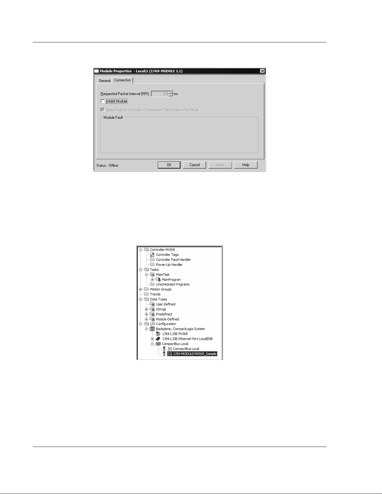
5 Click Next to continue.
6 Select the Request Packet Interval value for scanning the I/O on the module.
This value represents the minimum frequency the module will handle
scheduled events. This value should not be set to less than 1 millisecond.
Values between 1 and 10 milliseconds should work with most applications.
7 Save the module. Click OK to dismiss the dialog box. The Controller
Organization window now displays the module's presence. The following
illustration shows the Controller Organization window:
8 Copy the Controller Tags from the sample program.
9 Copy the User Defined Data Types from the sample program.
10 Copy the Ladder Rungs from the sample program.
11 Save and Download the new application to the controller and place the
processor in run mode.
Page 48 of 131 ProSoft Technology, Inc.
November 3, 2008
Page 49

Ladder Logic MVI69-103M ♦ CompactLogix or MicroLogix Platform
IEC 60870-5-103 Master Communication Module
3.3 Adding the Module to an Existing MicroLogix Project
If you are installing and configuring the module with a MicroLogix processor,
follow these steps. If you are using a CompactLogix processor, refer to the
previous section.
The first step in setting up the processor ladder file is to define the I/O type
module to the system. Start RSLogix 500, and follow these steps:
1 In RSLogix, open your existing application, or start a new application,
depending on your requirements.
2 Double-click the I/O Configuration icon located in the Controller folder in the
project tree. This action opens the I/O Configuration dialog box.
3 On the I/O Configuration dialog box, select "Other - Requires I/O Card Type
ID" at the bottom of the list in the right pane, and then double-click to open
the Module dialog box.
ProSoft Technology, Inc. Page 49 of 131
November 3, 2008
Page 50

MVI69-103M ♦ CompactLogix or MicroLogix Platform Ladder Logic
IEC 60870-5-103 Master Communication Module
4 Enter the values shown in the following illustration to define the module
correctly for the MicroLogix processor, and then click OK to save your
configuration.
The input words and output words parameter will depend on the Block
Transfer Size parameter you specify in the configuration file. Use the values
from the following table.
Block Transfer Size Inp ut Wo rd s Output Words
60 62 61
120 122 121
240 242 241
5 Click Next to continue.
6 After completing the module setup, the I/O configuration dialog box will
display the module's presence.
The last step is to add the ladder logic. If you are using the example ladder logic,
adjust the ladder to fit your application. Refer to the example Ladder Logic
section in this manual.
Download the new application to the controller and place the processor in run
mode. If you encounter errors, refer to Diagnostics and Troubleshooting (page
51) for information on how to connect to the module's Config/Debug port to use
its troubleshooting features.
Page 50 of 131 ProSoft Technology, Inc.
November 3, 2008
Page 51

Diagnostics and Troubleshooting MVI69-103M ♦ CompactLogix or MicroLogix Platform
IEC 60870-5-103 Master Communication Module
4 Diagnostics and Troubleshooting
In This Chapter
Reading Status Data from the Module ..................................................51
LED Status Indicators............................................................................69
The module provides information on diagnostics and troubleshooting in the
following forms:
Status data values are transferred from the module to the processor.
Data contained in the module can be viewed through the
Configuration/Debug port attached to a terminal emulator.
LED status indicators on the front of the module provide information on the
module's status.
4.1 Reading Status Data from the Module
The MVI69-103M module returns a status data set to the CompactLogix or
MicroLogix processor in each read block. This data is transferred to the
CompactLogix or MicroLogix processor continuously with each read block.
The Configuration/Debug port provides the following functionality:
Full view of the module's configuration data
View of the module's status data
Version Information
Control over the module (warm boot and cold boot)
Facility to upload and download the module's configuration file
4.1.1 The Configuration/Debug Menu
The Configuration and Debug menu for this module is arranged as a tree
structure, with the Main Menu at the top of the tree, and one or more sub-menus
for each menu command. The first menu you see when you connect to the
module is the Main menu.
Because this is a text-based menu system, you enter commands by typing the
command letter from your computer keyboard in the terminal application (for
example, HyperTerminal). The module does not respond to mouse movements
or clicks. The command executes as soon as you press the command letter —
you do not need to press [Enter]. When you type a command letter, a new
screen will be displayed in your terminal application.
ProSoft Technology, Inc. Page 51 of 131
November 3, 2008
Page 52

MVI69-103M ♦ CompactLogix or MicroLogix Platform Diagnostics and Troubleshooting
IEC 60870-5-103 Master Communication Module
Navigation
All of the sub-menus for this module contain commands to redisplay the menu or
return to the previous menu. You can always return from a sub-menu to the next
higher menu by pressing [M] on your keyboard.
The organization of the menu structure is represented in simplified form in the
following illustration:
The remainder of this section shows you the menus available for this module,
and briefly discusses the commands available to you.
Keystrokes
The keyboard commands on these menus are almost always non-case sensitive.
You can enter most commands in lower case or capital letters.
The menus use a few special characters ([?], [-], [+], [@]) that must be entered
exactly as shown. Some of these characters will require you to use the [Shift],
[Ctrl] or [Alt] keys to enter them correctly. For example, on US English
keyboards, enter the [?] command as [Shift][/].
Also, take care to distinguish capital letter [I] from lower case letter [l] (L) and
number [1]; likewise for capital letter [O] and number [0]. Although these
characters look nearly the same on the screen, they perform different actions on
the module.
4.1.2 Required Hardware
You can connect directly from your computer's serial port to the serial port on the
module to view configuration information, perform maintenance, and send
(upload) or receive (download) configuration files.
ProSoft Technology recommends the following minimum hardware to connect
your computer to the module:
80486 based processor (Pentium preferred)
1 megabyte of memory
At least one UART hardware-based serial communications port available.
USB-based virtual UART systems (USB to serial port adapters) often do not
function reliably, especially during binary file transfers, such as when
uploading/downloading configuration files or module firmware upgrades.
A null modem serial cable.
Page 52 of 131 ProSoft Technology, Inc.
November 3, 2008
Page 53

Diagnostics and Troubleshooting MVI69-103M ♦ CompactLogix or MicroLogix Platform
IEC 60870-5-103 Master Communication Module
4.1.3 Required Software
In order to send and receive data over the serial port (COM port) on your
computer to the module, you must use a communication program (terminal
emulator).
A simple communication program called HyperTerminal is pre-installed with
recent versions of Microsoft Windows operating systems. If you are connecting
from a machine running DOS, you must obtain and install a compatible
communication program. The following table lists communication programs that
have been tested by ProSoft Technology.
DOS ProComm, as well as several other terminal emulation programs
Windows 3.1 Terminal
Windows 95/98 HyperTerminal
Windows NT/2000/XP HyperTerminal
The module uses the Zmodem file transfer protocol to send (upload) and receive
(download) configuration files from your module. If you use a communication
program that is not on the list above, please be sure that it supports Zmodem file
transfers.
4.1.4 Using the Configuration/Debug Port
To connect to the module's Configuration/Debug port:
1 Connect your computer to the module's port using a null modem cable.
2 Start the communication program on your computer and configure the
communication parameters with the following settings:
Baud Rate 57,600
Parity None
Data Bits 8
Stop Bits 1
Software Handshaking None
3 Open the connection. When you are connected, press the [?] key on your
keyboard. If the system is set up properly, you will see a menu with the
module name followed by a list of letters and the commands associated with
them.
If there is no response from the module, follow these steps:
1 Verify that the null modem cable is connected properly between your
computer's serial port and the module. A regular serial cable will not work.
2 Verify that RSLinx is not controlling the COM port. Refer to Disabling the
RSLinx Driver for the Com Port on the PC (page 90).
3 Verify that your communication software is using the correct settings for baud
rate, parity and handshaking.
4 On computers with more than one serial port, verify that your communication
program is connected to the same port that is connected to the module.
If you are still not able to establish a connection, you can contact ProSoft
Technology Technical Support for further assistance.
ProSoft Technology, Inc. Page 53 of 131
November 3, 2008
Page 54

MVI69-103M ♦ CompactLogix or MicroLogix Platform Diagnostics and Troubleshooting
IEC 60870-5-103 Master Communication Module
4.1.5 Main Menu
When you first connect to the module from your computer, your terminal screen
will be blank. To activate the main menu, press the [?] key on your computer's
keyboard. If the module is connected properly, the following menu will appear on
your terminal screen:
Caution: Some of the commands available to you from this menu are designed for advanced
debugging and system testing only, and can cause the module to stop communicating with the
processor or with other devices, resulting in potential data loss or other failures. Only use these
commands if you are specifically directed to do so by ProSoft Technology Technical Support staff.
Some of these command keys are not listed on the menu, but are active nevertheless. Please be
careful when pressing keys so that you do not accidentally execute an unwanted command.
Viewing Block Transfer Statistics
Press [B] from the Main Menu to view the Block Transfer Statistics screen.
Use this command to display the configuration and statistics of the backplane
data transfer operations between the module and the processor. The information
on this screen can help determine if there are communication problems between
the processor and the module.
Tip: To determine the number of blocks transferred each second, mark the numbers displayed at a
specific time. Then some seconds later activate the command again. Subtract the previous
numbers from the current numbers and divide by the quantity of seconds passed between the two
readings.
Viewing Module Configuration
Press [C] to view the Module Configuration screen.
Use this command to display the current configuration and statistics for the
module.
Opening the Database Menu
Press [D] to open the Database View menu. Use this menu command to view the
current contents of the module's database.
Page 54 of 131 ProSoft Technology, Inc.
November 3, 2008
Page 55
Diagnostics and Troubleshooting MVI69-103M ♦ CompactLogix or MicroLogix Platform
IEC 60870-5-103 Master Communication Module
Opening the IEC-103 Master Menu
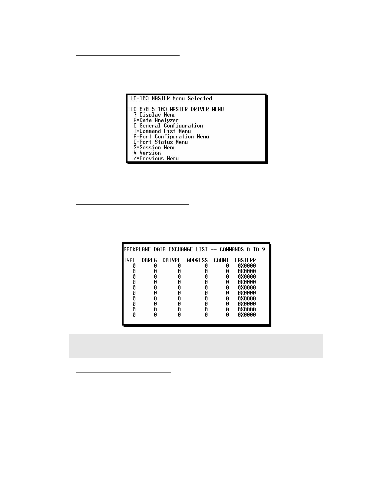
Press [I] from the Main Menu to open the IEC-870-5-103 Master Driver Menu.
Use this menu command to view detailed configuration information for the
module.
For more information about the commands on this menu, refer to IEC-103 Master
Driver Menu (page 58).
Viewing the Backplane Command List
Press [P] from the Main Menu to view the Backplane Data Exchange List. Use
this command to display the configuration and statistics of the backplane data
transfer operations.
Tip: Repeat this command at one-second intervals to determine the number of blocks transferred
each second.
Receiving the Configuration File
Press [R] to download (receive) the current configuration file from the module.
For more information on receiving and sending configuration files, please see
Uploading and Downloading the Configuration File (page 31).
ProSoft Technology, Inc. Page 55 of 131
November 3, 2008
Page 56

MVI69-103M ♦ CompactLogix or MicroLogix Platform Diagnostics and Troubleshooting
IEC 60870-5-103 Master Communication Module
Sending the Configuration File
Press [S] to upload (send) an updated configuration file to the module. For more
information on receiving and sending configuration files, please see Uploading
and Downloading the Configuration File (page 31).
Viewing Version Information
Press [V] to view Version information for the module.
Use this command to view the current version of the software for the module, as
well as other important values. You may be asked to provide this information
when calling for technical support on the product.
Values at the bottom of the display are important in determining module
operation. The Program Scan Counter value is incremented each time a
module's program cycle is complete.
Tip: Repeat this command at one-second intervals to determine the frequency of program
execution.
Exiting the Program
Caution: Some of the commands available to you from this menu are designed for advanced
debugging and system testing only, and can cause the module to stop communicating with the
processor or with other devices, resulting in potential data loss or other failures. Only use these
commands if you are specifically directed to do so by ProSoft Technology Technical Support staff.
Some of these command keys are not listed on the menu, but are active nevertheless. Please be
careful when pressing keys so that you do not accidentally execute an unwanted command.
Press [Esc] to restart the module and force all drivers to be loaded. The module
will use the configuration stored in the module's Flash ROM to configure the
module.
Warm Booting the Module
Caution: Some of the commands available to you from this menu are designed for advanced
debugging and system testing only, and can cause the module to stop communicating with the
processor or with other devices, resulting in potential data loss or other failures. Only use these
commands if you are specifically directed to do so by ProSoft Technology Technical Support staff.
Some of these command keys are not listed on the menu, but are active nevertheless. Please be
careful when pressing keys so that you do not accidentally execute an unwanted command.
Press [W] from the Main Menu to warm boot (restart) the module. This command
will cause the program to exit and reload, refreshing configuration parameters
that must be set on program initialization. Only use this command if you must
force the module to re-boot.
Page 56 of 131 ProSoft Technology, Inc.
November 3, 2008
Page 57

Diagnostics and Troubleshooting MVI69-103M ♦ CompactLogix or MicroLogix Platform
IEC 60870-5-103 Master Communication Module
4.1.6 Database View Menu
Press [D] from the Main Menu to open the Database View menu. Use this menu
command to view the current contents of the module's database. Press [?] to
view a list of commands available on this menu.
Viewing Database Pages 0 to 3000
The database is divided into pages that correspond with a specific number of
registers. The total number of database pages and registers depends on the
memory capacity and configuration of the module.
Use the keyboard commands [0] through [3] to display database contents
starting from 0 (zero), 1000, 2000 and 3000 respectively.
Moving Back Through 5 Pages of Registers
Press [-] from the Database View menu to skip back to the previous 500
registers of data.
Viewing the Previous 100 Registers of Data
Press [P] from the Database View menu to display the previous 100 registers of
data.
Skipping 500 Registers of Data
Hold down [Shift] and press [=] to skip forward to the next 500 registers of data.
ProSoft Technology, Inc. Page 57 of 131
November 3, 2008
Page 58

MVI69-103M ♦ CompactLogix or MicroLogix Platform Diagnostics and Troubleshooting
IEC 60870-5-103 Master Communication Module
Viewing the Next 100 Registers of Data
Press [N] from the Database View menu to select and display the next 100
registers of data.
Viewing Data in Decimal Format
Press [D] to display the data on the current page in decimal format.
Viewing Data in Hexadecimal Format
Press [H] to display the data on the current page in hexadecimal format.
Viewing Data in Floating Point Format
Press [F] from the Database View menu. Use this command to display the data
on the current page in floating point format. The program assumes that the
values are aligned on even register boundaries. If floating-point values are not
aligned as such, they are not displayed properly.
Viewing Data in ASCII (Text) Format
Press [A] to display the data on the current page in ASCII format. This is useful
for regions of the database that contain ASCII data.
Returning to the Main Menu
Press [M] to return to the Main Menu.
4.1.7 IEC-103 Master Driver Menu
Press [I] from the Main Menu to open the IEC-870-5-103 Master Driver Menu.
Use this menu command to view detailed configuration information for the
module.
Page 58 of 131 ProSoft Technology, Inc.
November 3, 2008
Page 59

Diagnostics and Troubleshooting MVI69-103M ♦ CompactLogix or MicroLogix Platform
IEC 60870-5-103 Master Communication Module
Opening the Data Analyzer Menu
Press [A] to open the Data Analyzer Menu. Use this command to view all bytes
of data transferred on each port. Both the transmitted and received data bytes
are displayed. Refer to Data Analyzer for more information about this menu.
Important: When in analyzer mode, program execution will slow down. Only use this tool during a
troubleshooting session. Before disconnecting from the Config/Debug port, please press [S] to stop
the data analyzer, and then press [M] to return to the main menu. This action will allow the module
to resume its normal high speed operating mode.
Viewing General Configuration
Press [C] from the IEC-103 Master Driver Menu to display the general
configuration for the protocol. The following illustration shows an example of the
Module Configuration screen:
The Busy/Idle message indicates the current activity state of the module. "Idle"
means it is waiting to execute a command. "Busy" means it is executing a
command and is waiting for the response to the request. This does not include
the normal class 1 and 2 polls as these are automatically generated.
The counter data displays the number of memory areas allocated for the
application layer. When no packets are pending, the counts should all be 0. If
messages are waiting to be sent, the applRec count will indicate the number
waiting to be sent. If many messages are received at the same time, the applRec
count will indicate the number of packets that must be processed. The "anything"
count indicates any other buffer area that is allocated and must be processed by
the application.
Opening the IEC-870-Master Command List Menu
Press [I] from the IEC-103 Master Driver Menu to open the ICE-870 Master
Command List menu. Use this command to view the configured command list for
the module.
For more information about the commands on this menu, refer to IEC-870-Master
Command List Menu (page 61).
ProSoft Technology, Inc. Page 59 of 131
November 3, 2008
Page 60

MVI69-103M ♦ CompactLogix or MicroLogix Platform Diagnostics and Troubleshooting
IEC 60870-5-103 Master Communication Module
Opening the Port Configuration Menu
Press [P] from the IEC-103 Master Driver Menu to open the Port Configuration
menu. Use this command to view the port configuration information for each of
the application ports.
The Port Configuration Menu section has more information about the commands
on this menu.
Opening the Port Status Menu
Press [Q] from the IEC-103 Master Driver Menu to open the Port Status menu.
Use this command to verify the status of the master commands sent through the
port. If the display indicates a communication error, you should compare the
generated error code with the command error codes listed in the Appendices of
this manual.
The Port Status Menu section has more information about the commands on this
menu.
Opening the Session Configuration Menu
Press [S] to open the Session Configuration menu. Use this command to view
the session configuration data.
Refer to Session Configuration Menu (page 66) for more information about the
commands on this menu.
Page 60 of 131 ProSoft Technology, Inc.
November 3, 2008
Page 61

Diagnostics and Troubleshooting MVI69-103M ♦ CompactLogix or MicroLogix Platform
IEC 60870-5-103 Master Communication Module
Opening the Sector Menu
Press [1] from the IEC-103 Master Driver Menu to open the Sector Configuration
menu. Use this command to view the Sector Configuration data.
The Sector Configuration Menu section has more information about the
commands on this menu.
Viewing Master Driver Version Information
Press [V] from the IEC-103 Master Driver Menu to view the master driver version
information.
Returning to the Main Menu
Press [M] to return to the Main Menu.
4.1.8 IEC-870-Master Command List Menu
Press [I] from the IEC-103 Master Driver Menu to open the ICE-870 Master
Command List menu. Use this command to view the configured command list for
the module.
ProSoft Technology, Inc. Page 61 of 131
November 3, 2008
Page 62

MVI69-103M ♦ CompactLogix or MicroLogix Platform Diagnostics and Troubleshooting
IEC 60870-5-103 Master Communication Module
Redisplaying the Menu
Press [?] to display the current menu. Use this command when you are looking
at a screen of data, and want to view the menu choices available to you.
Redisplaying the Current Page
Press [S] to display the current page of data.
Moving Back Through 5 Pages of Registers
Press [-] from the Database View menu to skip back to the previous 500
registers of data.
Viewing the Previous 100 Registers of Data
Press [P] from the Database View menu to display the previous 100 registers of
data.
Skipping 500 Registers of Data
Hold down [Shift] and press [=] to skip forward to the next 500 registers of data.
Viewing the Next 100 Registers of Data
Press [N] from the Database View menu to select and display the next 100
registers of data.
Returning to the Main Menu
Press [M] to return to the Main Menu.
4.1.9 Port Configuration Menu
Press [P] from the IEC-103 Master Driver Menu to open the Port Configuration
menu. Use this command to view the port configuration information for each of
the application ports.
Page 62 of 131 ProSoft Technology, Inc.
November 3, 2008
Page 63

Diagnostics and Troubleshooting MVI69-103M ♦ CompactLogix or MicroLogix Platform
IEC 60870-5-103 Master Communication Module
Redisplaying the Menu
Press [?] to display the current menu. Use this command when you are looking
at a screen of data, and want to view the menu choices available to you.
Redisplaying the Current Page
Press [S] to display the current page of data.
Displaying the Next Page
Press [N] to display the next 100 registers. Use this command to step forward
through the data a page at a time.
Displaying the Previous Page
Press [P] to display the previous 100 registers. Use this command to step
backward through the data a page at a time.
Returning to the Main Menu
Press [M] to return to the Main Menu.
4.1.10 Port Status Menu
Press [Q] from the IEC-103 Master Driver Menu to open the Port Status menu.
Use this command to view the communication status information for each
application port.
Redisplaying the Menu
Press [?] to display the current menu. Use this command when you are looking
at a screen of data, and want to view the menu choices available to you.
Redisplaying the Current Page
Press [S] to display the current page of data.
ProSoft Technology, Inc. Page 63 of 131
November 3, 2008
Page 64
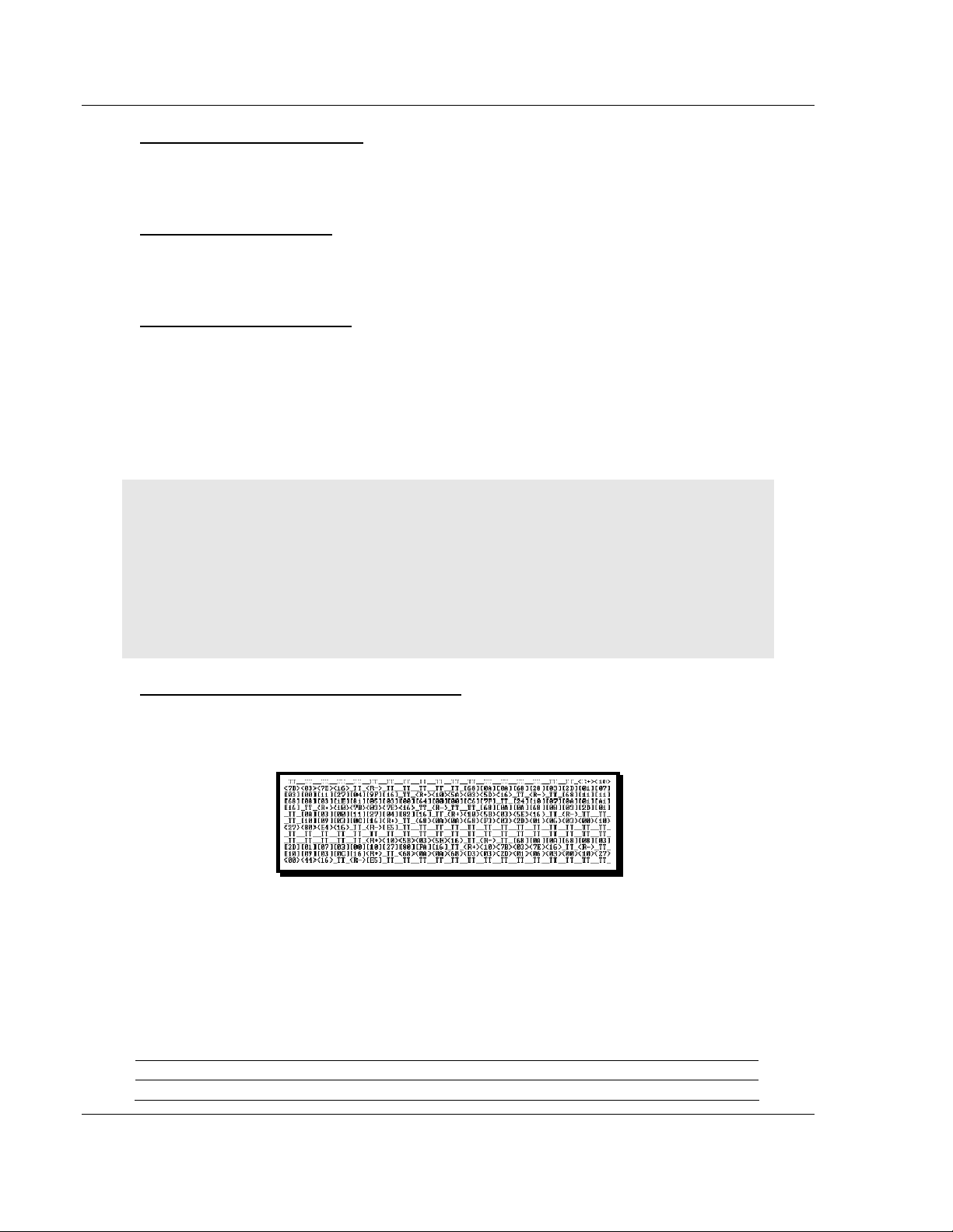
MVI69-103M ♦ CompactLogix or MicroLogix Platform Diagnostics and Troubleshooting
IEC 60870-5-103 Master Communication Module
Displaying the Previous Page
Press [P] to display the previous 100 registers. Use this command to step
backward through the data a page at a time.
Displaying the Next Page
Press [N] to display the next 100 registers. Use this command to step forward
through the data a page at a time.
Returning to the Main Menu
Press [M] to return to the Main Menu.
4.1.11 Data Analyzer
The data analyzer mode allows you to view all bytes of data transferred on each
port. Both the transmitted and received data bytes are displayed. Use of this
feature is limited without a thorough understanding of the protocol.
Note: The Port selection commands on the Data Analyzer menu differs very slightly in different
modules, but the functionality is basically the same. Use the illustration above as a general guide
only. Refer to the actual data analyzer menu on your module for the specific port commands to
use.
Important: When in analyzer mode, program execution will slow down. Only use this tool during a
troubleshooting session. Before disconnecting from the Config/Debug port, please press [S] to stop
the data analyzer, and then press [M] to return to the main menu. This action will allow the module
to resume its normal high speed operating mode.
Analyzing Data for the first application port
Press [1] to display I/O data for the first application port in the Data Analyzer.
The following illustration shows an example of the Data Analyzer output.
Analyzing Data for the second application port
Press [2] to display I/O data for the second application port in the Data Analyzer.
Displaying Timing Marks in the Data Analyzer
You can display timing marks for a variety of intervals in the data analyzer
screen. These timing marks can help you determine communication-timing
characteristics.
Key Interval
[5] 1 milliseconds ticks
Page 64 of 131 ProSoft Technology, Inc.
November 3, 2008
Page 65
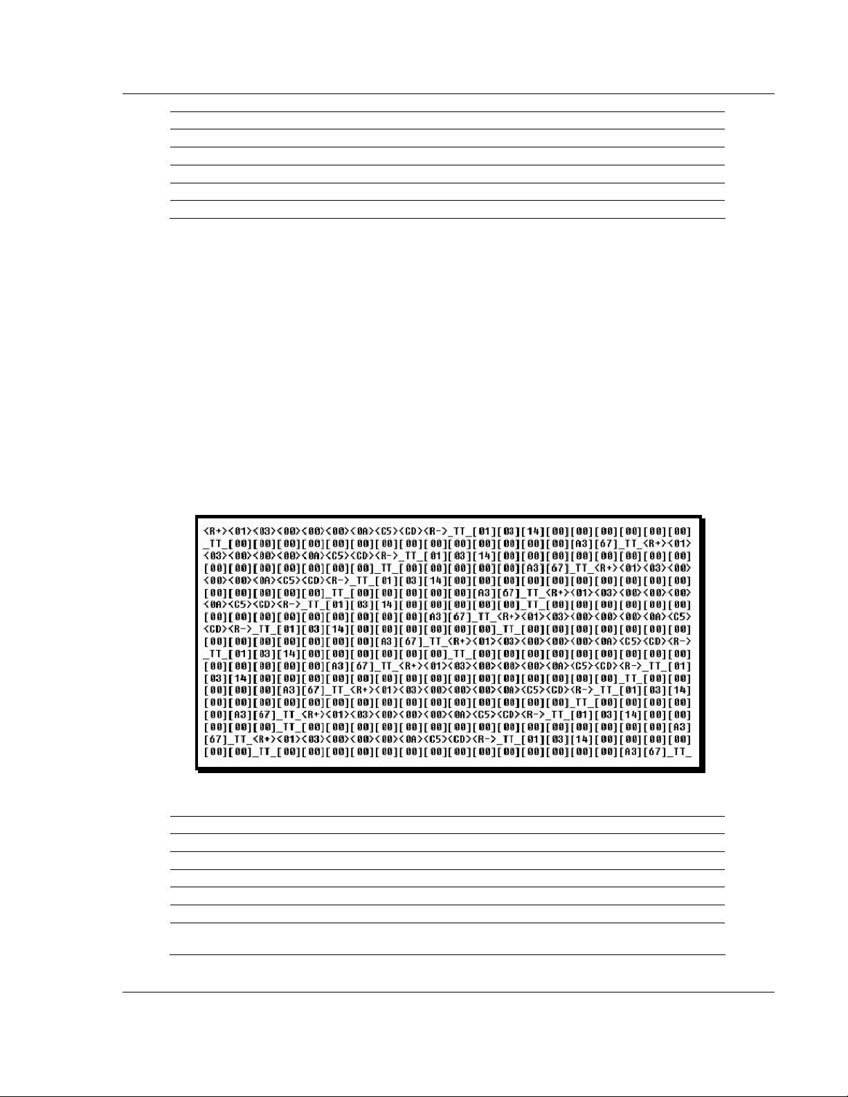
Diagnostics and Troubleshooting MVI69-103M ♦ CompactLogix or MicroLogix Platform
IEC 60870-5-103 Master Communication Module
Key Interval
[6] 5 milliseconds ticks
[7] 10 milliseconds ticks
[8] 50 milliseconds ticks
[9] 100 milliseconds ticks
[0] Turn off timing marks
Removing Timing Marks in the Data Analyzer
Press [0] to turn off timing marks in the Data Analyzer screen.
Viewing Data in Hexadecimal Format
Press [H] to display the data on the current page in hexadecimal format.
Viewing Data in ASCII (Text) Format
Press [A] to display the data on the current page in ASCII format. This is useful
for regions of the database that contain ASCII data.
Starting the Data Analyzer
Press [B] to start the data analyzer. After the key is pressed, all data transmitted
and received on the currently selected port will be displayed. The following
illustration shows an example.
The Data Analyzer displays the following special characters:
Character Definition
[ ] Data enclosed in these characters represent data received on the port.
< > Data enclosed in these characters represent data transmitted on the port.
<R+> These characters are inserted when the RTS line is driven high on the port.
<R-> These characters are inserted when the RTS line is dropped low on the port.
<CS> These characters are dis played when the CTS line is recognized high.
_TT_
These characters are displayed when the timing mark interval has been reached.
This parameter is user defined.
ProSoft Technology, Inc. Page 65 of 131
November 3, 2008
Page 66
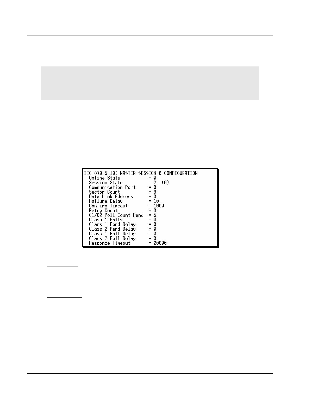
MVI69-103M ♦ CompactLogix or MicroLogix Platform Diagnostics and Troubleshooting
IEC 60870-5-103 Master Communication Module
Stopping the Data Analyzer
Press [S] to stop the data analyzer. Use this option to freeze the display so the
data can be analyzed. To restart the analyzer, press [B].
Important: When in analyzer mode, program execution will slow down. Only use this tool during a
troubleshooting session. Before disconnecting from the Config/Debug port, please press [S] to stop
the data analyzer, and then press [M] to return to the main menu. This action will allow the module
to resume its normal high speed operating mode.
Returning to the Main Menu
Press [M] to return to the Main Menu.
4.1.12 Session Configuration Menu
Press [S] from the IEC-103 Master Driver Menu to open the Session
Configuration menu. Use this command to view the session configuration for
each controlled device.
Online State
The Online State indicator displays 0 if the module is not online, 1 if the module
is online.
Session State
The Session State indicator displays 1 if there is a configuration error, or 2 if the
module is ready for communication. If the session is not in use, the Session State
indicator displays 0.
Page 66 of 131 ProSoft Technology, Inc.
November 3, 2008
Page 67

Diagnostics and Troubleshooting MVI69-103M ♦ CompactLogix or MicroLogix Platform
IEC 60870-5-103 Master Communication Module
4.1.13 Sector Configuration Menu
Press [1] from the IEC-103 Master Driver Menu to open the Sector Configuration
menu. Use this command to view the contents of the Sector Configuration
Databases for each session (controlled device). The module supports up to three
sectors (databases) per session.
Redisplaying the Menu
Press [?] to display the current menu. Use this command when you are looking
at a screen of data, and want to view the menu choices available to you.
Opening the Sector Database Menu
Press [D] from the Sector Configuration menu to open the Sector Database
menu. Use this command to look at the configuration and current value for each
point.
The IEC-870-Master Command List Menu section has more information about
the commands on this menu.
Redisplaying the Current Page
Press [S] to display the current page of data.
Displaying the Next Page
Press [N] to display the next 100 registers. Use this command to step forward
through the data a page at a time.
Displaying the Previous Page
Press [P] to display the previous 100 registers. Use this command to step
backward through the data a page at a time.
Returning to the Main Menu
Press [M] to return to the Main Menu.
ProSoft Technology, Inc. Page 67 of 131
November 3, 2008
Page 68

MVI69-103M ♦ CompactLogix or MicroLogix Platform Diagnostics and Troubleshooting
IEC 60870-5-103 Master Communication Module
4.1.14 Sector Database Menu
Press [D] from the Sector Configuration menu to open the Sector Database
menu. Use this command to display the sector database values. Each session
(controlled device) contains one or more data sets (sectors) that are defined by
the vendor of the device.
Redisplaying the Menu
Press [?] to display the current menu. Use this command when you are looking
at a screen of data, and want to view the menu choices available to you.
Redisplaying the Current Page
Press [S] to display the current page of data.
Viewing ASDU n Data
Press keys [0] (zero) through [4] to display ASDU (Application Data Service Unit)
data for each of the supported data types. Refer to [IEC-103 Master Session x
Sector x] for a list of ASDU types.
Page 68 of 131 ProSoft Technology, Inc.
November 3, 2008
Page 69

Diagnostics and Troubleshooting MVI69-103M ♦ CompactLogix or MicroLogix Platform
IEC 60870-5-103 Master Communication Module
Listing ASDU point counts
Press [5] to display the ASDU point counts for each ASDU type.
Returning to the Main Menu
Press [M] to return to the Main Menu.
4.2 LED Status Indicators
The LEDs indicate the module's operating status as follows:
Module Color Status Indication
CFG Green
Amber
Status
BP ACT Amber
OK Red/
Green
On
Off No data is being transferred on the Configuration/Debug port.
On Data being transferred on the first applicatio n port P1 Green
Off No data being transferred on port
On Data being transferred on the second app lication port P2 Green
Off No data being transferred on port
Off The MVI69-103M is working normally. APP
On
On
Off
Off
Green The module is operating normally.
Red
Off The battery voltage is OK and functioning. BAT Red
On
Data is being transferred between the module and a remote
terminal using the Configuration/Debug port.
The MVI69-103M module program has recognized a
communication error.
The LED is on when the module is performing a write
operation on the backplane.
The LED is off when the module is performing a read
operation on the backplane. Under normal operation, the LED
should blink rapidly on and off.
The card is not receiving any power and is not securely
plugged into the rack.
The program has detected an error or is being configured. If
the LED remains red for over 10 seconds, the program has
probably halted. Remove the card from the rack and re-insert
the card to restart the module's program.
The battery voltage is low or battery is not present. Allow
battery to charge by keeping module plugged into rack for 24
hours. If BAT LED still does not go off, contact ProSoft
Technology, as this is not a user serviceable item.
ProSoft Technology, Inc. Page 69 of 131
November 3, 2008
Page 70

MVI69-103M ♦ CompactLogix or MicroLogix Platform Diagnostics and Troubleshooting
IEC 60870-5-103 Master Communication Module
4.2.1 Clearing a Fault Condition
Typically, if the OK LED on the front of the module turns red for more than ten
seconds, a hardware problem has been detected in the module, or the program
has exited.
To clear the condition, follow these steps:
1 Turn off power to the rack
2 Remove the card from the rack
3 Verify that all jumpers are set correctly
4 If the module requires a Compact Flash card, verify that the card is installed
correctly
5 Re-insert the card in the rack and turn the power back on
6 Verify the configuration data being transferred to the module from the
CompactLogix or MicroLogix processor.
If the module's OK LED does not turn green, verify that the module is inserted
completely into the rack. If this does not cure the problem, contact ProSoft
Technology Support.
4.2.2 Troubleshooting
Use the following troubleshooting steps if you encounter problems when the
module is powered up. If these steps do not resolve your problem, please contact
ProSoft Technology Technical Support.
Processor Errors
Problem Description Steps to take
Processor Fault
Processor I/O LED
flashes
Verify that the module is plugged into the slot that has been configured for
the module.
Verify that the slot in the rack configuration has been set up correctly in the
ladder logic.
This indicates a problem with backplane communications. Verify that all
modules in the rack are configured in the ladder logic.
Module has a power supply distance rating of 2 on Compact Logix. The
module must be within 2 slots of the power supply on Compact Logix, or that
the MicroLogix backplane can supply the 800ma required for the modul e.
Module Errors
Problem Description Steps to take
BP ACT LED remains
off or blinks slowly
OK LED remains red
This indicates that backplane transfer operations are failing. Connect to the
module's Configuration/Debug port to check this.
To establish backplane communications, verify the following items:
The processor is in Run mode.
The backplane driver is lo aded in the module.
The module is configured for read and write block data transfer.
The ladder logic handles all read and write block situations.
The module is configured in the processor.
The program has halted or a critical error has occurred. Connect to the
Configuration/Debug port to see if the module is running. If the program has
halted, turn off power to the rack, remove the card from the rack and reinsert the card in the rack, and then restore power to the rack.
Page 70 of 131 ProSoft Technology, Inc.
November 3, 2008
Page 71

Reference MVI69-103M ♦ CompactLogix or MicroLogix Platform
IEC 60870-5-103 Master Communication Module
5 Reference
In This Chapter
Product Specifications...........................................................................71
Functional Overview..............................................................................73
Cable Connections................................................................................90
MVI69-103M Status Data Area..............................................................95
Database Form......................................................................................99
Command List Form............................................................................101
Protocol Support..................................................................................103
Protocol Interoperability Documentation..............................................113
5.1 Product Specifications
The MVI69 IEC 60870-5-103 Master Communication Module allows
CompactLogix I/O compatible processors to interface easily with IEC 60870-5103 slave (controlled unit) protection devices. Devices commonly supporting the
protocol include relays, breakers, sub-station communication modules and other
serial communication devices used in power monitoring.
The MVI69-103M supports up to 16 total field devices between the module's two
IEC 60870-5-103 Master ports. The module's communication ports can be
independently configured, allowing two separate field networks to be
implemented. The field device data is exchanged between the MVI module and
the CompactLogix processor over the backplane.
The MVI69-103M module is a powerful communication interface for
CompactLogix processors. Developed under license from Rockwell Automation,
the module incorporates proprietary backplane technology that enables powerful
data access to the CompactLogix processor.
5.1.1 General Specifications
Single Slot - 1769 backplane compatible
The module is recognized as an Input/Output module and has access to
processor memory for data transfer between processor and module
Ladder Logic is used for data transfer between module and processor.
Sample ladder file included.
Configuration data obtained from configuration text file downloaded to
module. Sample configuration file included.
Supports all CompactLogix processors: L20/L23/L30/L31/L32/L35, L43 and
L45 (L43 and L45 supported with RSLogix 5000 v16.03 or later)
Also supports MicroLogix 1500 LRP
ProSoft Technology, Inc. Page 71 of 131
November 3, 2008
Page 72

MVI69-103M ♦ CompactLogix or MicroLogix Platform Reference
IEC 60870-5-103 Master Communication Module
5.1.2 Hardware Specifications
Specification Description
Dimensions Standard 1769 Single-slot module
Current Load 800 mA max@ 5 VDC
Power supply distance rating of 2
Operating Temp. 0 to 60°C (32 to 140°F)
Storage Temp. -40 to 85°C (-40 to 185°F)
Relative Humidity 5% to 95% (non-condensing)
LED Indicators Power and Module Status
Application Status
Serial Port Activity
Error Status
CFG Port (CFG) RJ45 (DB-9F with supplied cable)
RS-232 only
No hardware handshaking
App Ports (P1,P2) (Serial modules) RJ45 (DB-9F with supplied cable)
RS-232, RS-422 and RS-485 modes supported.
Both ports operate as individual IEC 60870-3-103
controlling units (masters)
500V Optical isolation from backplane
Shipped with Unit RJ45 to DB-9M cables for each port
6-foot RS-232 configuration Cable
5.1.3 Functional Specifications
The MVI69-103M module supports the IEC 60870-5-103 protocol to the following
specifications:
The IEC 60870-5-103 communication driver is built in accordance to the
approved IEC specification
User-definable module memory usage
The module has two independent master ports, each configurable via a
simple configuration file
Supports up to 16 sessions (controlled devices) between the two ports
Supports up to three sectors (separate databases) for each session, with
individual database definition for each sector
Total of 1000 user configurable commands to control data transfer to/from
devices (controlled devices)
Supports clock synchronization from/to the processor
Event data received from the Control Devices updates the module database
(Date and Time stamping is not stored or used by module)
Class 1 and Class 2 delay parameters are configurable for each session
An IEC Interoperability Document for the module is available from the web
site, which fully documents data types supported by the module
Page 72 of 131 ProSoft Technology, Inc.
November 3, 2008
Page 73

Reference MVI69-103M ♦ CompactLogix or MicroLogix Platform
IEC 60870-5-103 Master Communication Module
5.2 Functional Overview
This section provides an overview of how the MVI69-103M module transfers data
using the 103M protocol. You should understand the important concepts in this
chapter before you begin installing and configuring the module.
The standards used to build the module are listed in the following table.
Publication Title
IEC 60870-5-103 Companion Standard for the informative interface of protection equipment.
IEC 60870-5-103
Annex A
IEC 60870-5-1 Transmission F r ame F ormats
IEC 60870-5-2 Link Transmission Procedures
IEC 60870-5-3 General Structure of Application Data
IEC 60870-5-4 Definition and Coding of Application Information Elements
IEC 60870-5-5 Basic Application Functions
These documents should be obtained, reviewed, and understood in order to fully
appreciate the protocol implementation. Most of the complexity of the protocol is
hidden from the user and simplified in the application of the module. Detailed
questions of about the protocol can be answered by reading these documents. In
addition to calling our technical support group, there is also help available for the
protocol using the following mail list Web Site:
www.TriangleMicroWorks.com/iec870-5
(http://www.trianglemicroworks.com/iec870-5). Go to this site to join the mail list
and to review questions and answers from mail list users.
Generic functions --Examples of constructing a directory
5.2.1 General Concepts
The following discussion explains several concepts that are important for
understanding the operation of the MVI69-103M module.
Module Power Up
On power up the module begins performing the following logical functions:
1 Initialize hardware components
o Initialize CompactLogix or MicroLogix backplane driver
o Test and clear all RAM
o Initialize the serial communication ports
2 Read configuration for module from IEC103M.CFG file on Compact Flash
Disk
3 Initialize the databases and ports
4 Set up the serial communication interface for the debug/configuration port
After the module has received the configuration, the module will begin receiving
and transmitting messages with devices on the serial networks.
ProSoft Technology, Inc. Page 73 of 131
November 3, 2008
Page 74

MVI69-103M ♦ CompactLogix or MicroLogix Platform Reference
IEC 60870-5-103 Master Communication Module
Main Logic Loop
Upon completing the power up configuration process, the module enters an
infinite loop that performs the following functions:
Backplane Data Transfer
The MVI69-103M module communicates directly over the CompactLogix or
MicroLogix backplane. Data travels between the module and the CompactLogix
or MicroLogix processor across the backplane using the module's input and
output images. The update frequency of the data is determined by the scan rate
defined by the user for the module and the communication load on the module.
Typical updates are in the range of 1 to 10 milliseconds.
Data received by the master drivers is placed in the module's input image. This
data is processed by the ladder logic in the CompactLogix or MicroLogix
processor.
The processor inserts data in the module's output image to transfer to the
module. The module's program extracts the data and transmits the data out to
the master driver to the serial network. Additionally, the CompactLogix or
MicroLogix processor can send special control blocks to the module to instruct it
to perform a special task.
Page 74 of 131 ProSoft Technology, Inc.
November 3, 2008
Page 75

Reference MVI69-103M ♦ CompactLogix or MicroLogix Platform
IEC 60870-5-103 Master Communication Module
The following illustration shows the data transfer method used to move data
between the CompactLogix or MicroLogix processor, the MVI69-103M module,
and the serial network.
All data transferred between the module and the processor over the backplane is
through the input and output images. Ladder logic must be written in the
CompactLogix or MicroLogix processor to interface the input and output image
data defined in the controller tags. The user is responsible for handling and
interpreting all data received on the application ports and transferred to the input
image.
Data Types and Mapping
When interfacing data in the processor to that of the IEC 60870-5-103 protocol, it
is important that the user understand the mapping of the data types to their
corresponding representation in the modules database. The following table lists
the data types supported by the module and their associated storage
representation:
Type ID Description Data Representation
1
2
Time-tagged messages with each data
point represented by two bits.
Time-tagged messages with relative
time with each point represented by
two bits.
Dual-bit status (7.2.6.5 with 00b (0 decimal) =
not used, 01b (1 decimal) = Off, 10b (2
decimal) = On and 11b (3 decimal) = not used
Dual-bit status (7.2.6.5 with 00b (0 decimal) =
not used, 01b (1 decimal) = Off, 10b (2
decimal) = On and 11b (3 decimal) = not used
ProSoft Technology, Inc. Page 75 of 131
November 3, 2008
Page 76

MVI69-103M ♦ CompactLogix or MicroLogix Platform Reference
IEC 60870-5-103 Master Communication Module
Type ID Description Data Representation
3
4
5
9
20
* The words should be swapped in the ladder logic.
Measurands with quality descriptor.
The lower 3 bits of the values
represented in this data type contain
status information. The upper 13 bits of
the value contained a signed, 12-bit
number. This data type will return from
1 to 4 values. The number of words
received is dependant on the
information object number and the
slave device.
Time-tagged measurands with relative
time with the value in the packet
represented by a single floating point
number.*
Identification data composed of 12
characters of data. Each point in
defined of this data type should reserve
12 bytes (6-word addresses) in the
database for the data received.
Measurands with quality descriptor.
The lower 3 bits of the values
represented in this data type contain
status information. The upper 13 bits of
the value contained a signed, 12-bit
number. This data type will return from
1 to 9 values (some slaves may return
up to 16 values). The number of words
received is dependant on the
information object number and the
slave device.
General command to control a dualpoint object. Each command issued by
the module uses the values of two
adjacent bits in the database or an
override value specified by the user
command.
Measurand with quality descriptor (7.2.6.8)
Bit 0: 0 = No overflow, 1 = Overflow
Bit 1: 0 = Valid, 1 = Invalid
Bit 2: Reserved
Bits 3 to 25: Value from -1..+1-2
Short floating-point number stored in IEEE
STD 754 format (Fraction, Exponent, Sign)
(7.2.6.20)
Byte data as defined in 7.2.6.2. First 8 bytes
are characters 1 to 8 and last 4 bytes are
manufacture bytes either decimal (0 to 255) or
as ASCII characters.
Measurand with quality descriptor (7.2.6.8)
Bit 0: 0 = No overflow, 1 = Overflow
Bit 1: 0 = Valid, 1 = Invalid
Bit 2: Reserved
Bits 3 to 25: Value from -1..+1-2
Dual-bit status (7.2.6.4 with 00b (0 decimal) =
not used, 01b (1 decimal) = Off, 10b (2
decimal) = On and 11b (3 decimal) = not used
12
12
As shown in the previous table, all bit types are addressed as bits in the modules
database.
Addressing the Data Types
The following table shows an example of how to address the data types in the
MVI69-103M:
Data Type Address Type Length Example
1 Bit 2 bits
2 Bit 2 bits
3 Word 4 words Address 50 refers to word 50, 51, 52, and 53.
4 Double-word 2 words
5 Bit 12 bits
Address 160 refers to first and second bits from
word 10.
Address 160 refers to first and second bits from
word 10.
Address 40 refers to two consecutive words
starting at word 80.
Address 180 refers to 12 consecutive bits starting
at the LSB of word 90.
Page 76 of 131 ProSoft Technology, Inc.
November 3, 2008
Page 77

Reference MVI69-103M ♦ CompactLogix or MicroLogix Platform
IEC 60870-5-103 Master Communication Module
Data Type Address Type Length Example
9 Word 5 words
20 Bit 2 bits
Address 100 refers to 9 consecutive words starting
at word 100.
Address 160 refers to the first and second bits
from word 10.
Therefore, address 16000 represents bit zero in word 1000 of the module's
database. Short floating-point, 32-bit strings and integrated total values each
occupy a double-word space in the database. Therefore, short float database
address of 100 represents the two words, 200 and 201, in the modules database.
Identification objects are stored as byte values in the modules database.
Identification object address 1000 is stored in the module's database in word
addresses 500 to 505.
When setting the monitored data and commands, each point is defined by its
ASDU type, function code, and information number. Valid function codes are
listed in the following table.
Function Code Symbol Number
Distance Protection T(z) 128
Over-current Protection I> > 160
Transformer Differential
Protection
Line Differential Protection rIl 192
Global Function Type GLB 255
rIt 176
Refer to Protocol Interoperability Documentation for a full listing of the protocol
support offered by the module.
As blocks are transferred between the module and the processor, each block
contains block identification codes that define the content or function of the block
of data transferred. The block identification codes used by the module are
displayed in the following table.
Block Range Descriptions
-1 Null block
0 Null block
1 to 20 Read or write data
9901 User Constructed Command
9902 Command Control Block (Add command to Command List Queue)
9903 Event Messages from Master port
9950 Command List Error data
9970 Set PLC time using module's time
9971 Set module's time using CompactLogix or MicroLogix time
9998
9999
Warm Boot Request from CompactLogix or MicroLogix (Block contains no
data)
Cold Boot Request from CompactLogix or MicroLogix (Block contains no
data)
ProSoft Technology, Inc. Page 77 of 131
November 3, 2008
Page 78

MVI69-103M ♦ CompactLogix or MicroLogix Platform Reference
IEC 60870-5-103 Master Communication Module
Blocks -1 and 0 transfer status data from the module to the processor and they
contain no data when transferred from the processor to the module. Blocks 1 to
20 are utilized to transfer data stored or to be stored in the module's database.
These data blocks send data from module to the processor (monitored data
received from the devices on the serial network) and to send data from the
processor to the module (control data to send to the end devices). Block
identification codes 9901 to 9999 are used for special control blocks to control
the module.
Normal Data Transfer
Normal data transfer includes the transferring of data received by or to be
transmitted to the master drivers and the status data. These data are transferred
through read (input image) and write (output image) blocks.
Refer to Module Configuration for a description of the data objects used with the
blocks and the ladder logic required. The following topics discuss the structure
and function of each block.
Read Block
These blocks of data transfer information from the module to the CompactLogix
or MicroLogix processor. The structure of the input image used to transfer this
data is shown in the following table.
Offset Description Length
0 Read Block ID 1
1 Write Block ID 1
2 to (n+1) Read Data n
where
n = 60, 120, or 240 depending on the Block Transfer Size parameter (refer to the
configuration file).
The Read Block ID is an index value used to determine the location of where the
data will be placed in the CompactLogix or MicroLogix processor controller tag
array of module read data. The number of data words per transfer depends on
the configured Block Transfer Size parameter in the configuration file (possible
values are 60, 120, or 240).
The Write Block ID associated with the block requests data from the
CompactLogix or MicroLogix processor. Under normal, program operation, the
module sequentially sends read blocks and requests write blocks. For example, if
three read and two write blocks are used with the application, the sequence will
be as follows:
R1W1 R2W2 R3W1 R1W2 R2W1 R3W2 R1W1
This sequence will continue until interrupted by other write block numbers sent by
the controller or by a command request from a node on the 103M network or
operator control through the module's Configuration/Debug port.
Page 78 of 131 ProSoft Technology, Inc.
November 3, 2008
Page 79
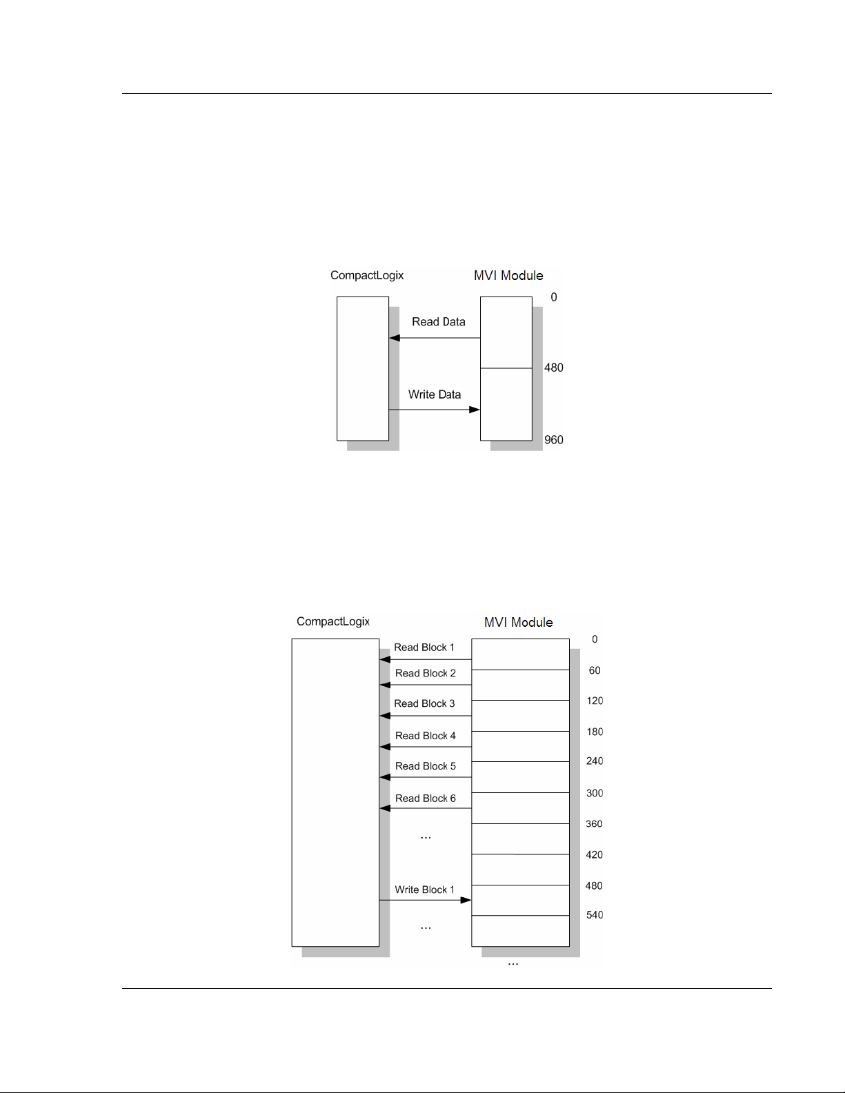
Reference MVI69-103M ♦ CompactLogix or MicroLogix Platform
IEC 60870-5-103 Master Communication Module
The following example shows a typical backplane communication application.
Assume that the backplane parameters are configured as follows:
Read Register Start: 0
Read Register Count: 480
Write Register Start: 480
Write Register Count: 480
The backplane communication would be configured as follows:
Database address 0 to 479 will be continuously transferred from the module to
the processor. Database address 480 to 959 will continuously be transferred
from the processor to the module.
The Block Transfer Size parameter basically configures how the Read Data and
Write Data areas are broken down into data blocks (60, 120, or 240).
If Block Transfer Size = 60:
ProSoft Technology, Inc. Page 79 of 131
November 3, 2008
Page 80
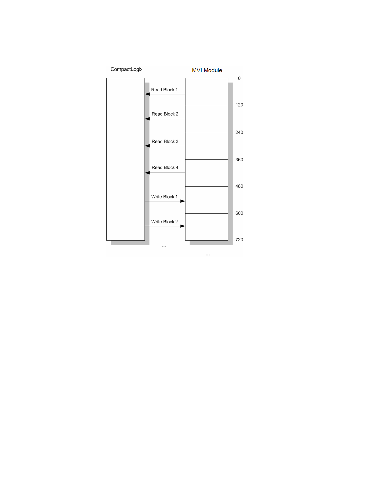
MVI69-103M ♦ CompactLogix or MicroLogix Platform Reference
IEC 60870-5-103 Master Communication Module
If Block Transfer Size = 120:
Page 80 of 131 ProSoft Technology, Inc.
November 3, 2008
Page 81
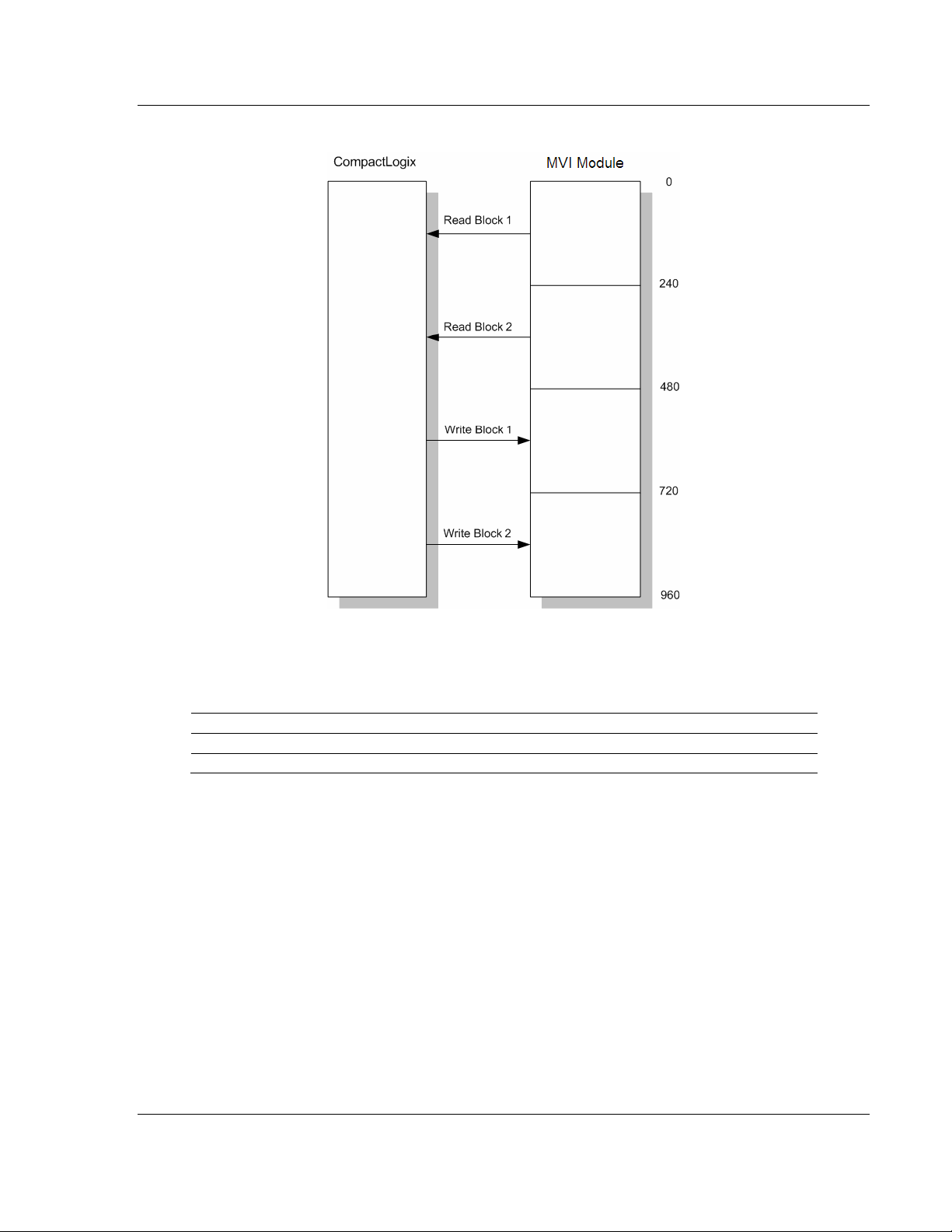
Reference MVI69-103M ♦ CompactLogix or MicroLogix Platform
IEC 60870-5-103 Master Communication Module
If Block Transfer Size = 240:
Write Block
These blocks of data transfer information from the CompactLogix or MicroLogix
processor to the module. The structure of the output image used to transfer this
data is shown in the following table.
Offset Description Length
0 Write Block ID 1
1 to n Write Data n
where
n = 60, 120, or 240 depending on the Block Transfer Size parameter (refer to the
configuration file).
The Write Block ID is an index value used to determine the location in the
module's database where the data will be placed.
How Data is Transferred
In order to understand how the data is transferred between the processor and the
module, you must understand the Read Data and Write Data area concept in the
module's database. The module's database can be partially, or totally divided into
Read Data Areas and Write Data Areas.
These areas are defined by the user when the configuration file is being edited.
The following parameters define the Read and Write data areas:
ProSoft Technology, Inc. Page 81 of 131
November 3, 2008
Page 82

MVI69-103M ♦ CompactLogix or MicroLogix Platform Reference
IEC 60870-5-103 Master Communication Module
Read Register Start = 0
Read Register Count = 120
Write Register Start = 200
Write Register Count = 120
Each area is broken down into blocks of 60 words. Therefore, the Read Register
Count and Write Register Count parameters should be multiples of 60.
The Read Data Area will be transferred from the module to the CompactLogix or
MicroLogix processor. The Write Data Area will be transferred from the
CompactLogix or MicroLogix processor to the module.
The following example shows the resulting data flow:
Command Control Blocks
Block identification codes greater than 9900 are utilized to perform special
functions in the module. Each control block recognized and used by the module
is defined in the following topics.
User Constructed Command Block (9901)
Block identification code 9901 issues one or more user constructed commands.
When the module receives a block 9901 identification code, it will place the
included commands into the command queue.
Word Offset in
Block
0 Block ID
1 Command Count
Data Field(s) Description
This field contains the block identification code of 9901
for the block.
This field defines the number of user commands
contained in the block. The valid range for the field is 1
to 10.
Page 82 of 131 ProSoft Technology, Inc.
November 3, 2008
Page 83

Reference MVI69-103M ♦ CompactLogix or MicroLogix Platform
IEC 60870-5-103 Master Communication Module
Word Offset in
Block
2 to 11 Command #1
12 to 21 Command #2
22 to 31 Command #3
32 to 41 Command #4
42 to 51 Command #5
Data Field(s) Description
Data required to build the user defined command in the
command queue.
Data required to build the user defined command in the
command queue.
Data required to build the user defined command in the
command queue.
Data required to build the user defined command in the
command queue.
Data required to build the user defined command in the
command queue.
The following fields are used for each 10-word record in the command list:
Word Offset Definitions Description
0 Database Index Address in module to associate with the command.
1 Session Index
2 Sector Index Sector index for session as defined in the module.
3 Data Type ASDU data type associated with the command.
4 Function Code Function Code for the command.
5 Point Index *
6 Override Flag Override flag for general command.
7 Override Value Override value for general command.
8 Reserved Reserved for future use.
9 Reserved Reserved for future use.
* Information
Number
Session index defined in the module to associate with the
command.
Information object address for the point on which the
command operates.
Refer to the command list section of this documentation for a detailed definition
of the fields contained in this block. They are the same as those used in
constructed the commands in the command list.
There is no response block built by the module to send back to the processor
after the block is processed. The commands are placed in the command queue
and issued at a high priority.
This block and block 9902 should be used when controlling double-point data
points in remote units using general commands. This provides complete control
of the slave devices under ladder logic control. Alternatively, the slaves can be
controlled by changing data in the database and having the data be transferred
using pre-constructed commands in the user's command list. Some points only
accept value of on for control (that is, LED reset or activate characteristic). For
these points, block 9901 and 9902 should only be utilized.
Command Control Block (9902)
The block 9902 identification code is used by the processor to send a list of
commands to be placed in the command queue from the user configured
command list. Commands placed in the queue with this method need not have
their enable bit set in the command list.
ProSoft Technology, Inc. Page 83 of 131
November 3, 2008
Page 84

MVI69-103M ♦ CompactLogix or MicroLogix Platform Reference
IEC 60870-5-103 Master Communication Module
Word Offset in
Block
0 Block ID
1 Command count
2 to 61
62 to n Spare Not Used
Data Field(s) Description
This field contains the value of 9902 identifying the enable
command to the module.
This field contains the number of commands to enable in the
command list. Valid values for this field are 1 to 50.
Command
Numbers to enable
These 50 words of data contain the command numbers in the
command list to enable. The commands in the list will be
placed in the command queue for immediate processing by
the module. The first command in the list has an index of 0.
There is no response to this block by the module. The module will place the
selected commands into the command queue. If the command references a unit
that is not defined, the command will not be placed in the command queue.
Normal processing of the command list will continue after the commands
specified in this block are processed.
For digital output control, the use of block 9901 and 9902 is preferred to the use
of the command list. The exact state of the output can be specified in the
command list and then the command can be enabled through the use of block
9902. When the user wishes to execute this command (knowing the state of the
command), can enable the command with the block 9902 request.
Event Message Block (9903)
Block identification code 9903 sends event messages received on the master
port to the processor.
Note: Events are recognized when using a COT = Spontaneous.
Word Offset in
Block
0 Read Block ID 9903
1 Write Block ID
2 Event Count
3 to 12 Event 1 Event message
13 to 22 Event 2 Event message
23 to 32 Event 3 Event message
33 to 42 Event 4 Event message
43 to 52 Event 5 Event message
Data Field(s) Description
This field contains the number of events present in the block.
Values of 1 to 20 are valid.
The format of each 10-word data region in the block is as follows:
Word Offset Definitions Description
0
1 ASDU Type
2
Session Index/Sector
Index
Function Code/Point
Index*
This field contains the session and sector indices used
to define the controlled unit in the module from which
the event was generated. The MSB contains the
session index and the LSB contains the sector index.
This field contains the ASDU type code for the data
contained in the message.
This field contains the function code and the point index
associated with the event message. The MSB contains
the function code and the LSB contains the point index.
Page 84 of 131 ProSoft Technology, Inc.
November 3, 2008
Page 85

Reference MVI69-103M ♦ CompactLogix or MicroLogix Platform
IEC 60870-5-103 Master Communication Module
Word Offset Definitions Description
3 Fault Number
4 Sec/milliseconds
5 Hr/Min.
6 Invalid/DST
7 Relative Time
8 to 9 Value
This is the fault number for the event if applicable. Only
valid for ASDU types 2 and 4.
This word contains the seconds and millisecond values
with a range of 0 to 59999 time at which the message
was generated by the slave device.
This word contains the hour and minutes the message
was generated by the slave. The MSB contains the
hour and the LSB contains the minute value.
This word contains two bits that relate to the time value
recorded in the slave device for the message. Bit 0
corresponds to the validity of the time (0=valid,
1=invalid) and Bit 1 defines if daylight savings time is
used in the time (0=no, 1=yes).
This field contains the relative time value if applicable to
the object. Only valid for ASDU types 2 and 4.
This double-word value contains the value for the point
index/function code in the event message. For ASDU
types 1 and 2, this value is only 2 bits wide. For ASDU
type 4, this double-word value contains the floatingpoint number (short circuit location).
In order for this feature to be activated, the event pass-through parameter must
be set. When a master driver receives an event message from a controlled
station, it will build an event message corresponding to the event in the event
buffer of the module. This buffer is then sent to the processor when any
messages are present. Therefore, these blocks are sent to the processor on a
high priority. After the block is sent, the event message is removed from the
module's event buffer.
If too many events are present in the buffer (>200), the module will set the event
message overflow flag in the error/status data area of the normal read data
block. There is no response block to be received by the module from the
processor.
Command List Error Data Block (9950)
Block 9950 identification code requests the Command List Error Table from the
module for the 1000 user configurable commands. The format for the block is
shown below:
Word Offset in
Block
0 Block ID
1
2
3 to n Spare Not Used
Data Field(s) Description
This field contains the value of 9950 identifying the block type
to the module.
Number of
Commands to
report
Start Index of First
Command
This field contains the number of commands to report in the
response message. The value has a range of 1 to 200.
This parameter sets the index in the command list where to
start. The first command in the list has a value of 0. The last
index in the list has a value of MaxCommands -1.
where
n = 60, 120, or 240 depending on the Block Transfer Size parameter (refer to the
configuration file).
ProSoft Technology, Inc. Page 85 of 131
November 3, 2008
Page 86

MVI69-103M ♦ CompactLogix or MicroLogix Platform Reference
IEC 60870-5-103 Master Communication Module
The module will respond to a valid request with a block containing the requested
error information. The format for the block is shown in the following table.
Word Offset in
Block
0 Read Block ID Read Block Identification
1 Write Block ID Write Block Identification (9950)
2
3
4 to 53
Data Field(s) Description
Number of
Commands
reported
Start Index of First
Command
Command List
Errors
This field contains the number of commands contained in the
block that must be processed by the PLC. This field will have
a value of 1 to 200.
This field contains the index in the command list for the first
value in the file. This field will have a value of 0 to
MaxCommands-1.
Each word of this area contains the last error value recorded
for the command. The command index of the first value
(offset 4) is specified in word 3 of the block. The number of
valid command errors in the block is set in word 2 of the
block. Refer to the command error list to interpret the error
codes reported.
Set CompactLogix or MicroLogix Time Block (9970)
Block 9970 identification code requests the module's date and time. Use this data
to set the PLC clock.
Word Offset in
Block
0 Block ID
1 to n Not Used Not Used
Data Field(s) Description
This field contains the value of 9970 identifying the block type
to the module.
where
n = 60, 120, or 240 depending on the Block Transfer Size parameter (refer to the
configuration file).
The module will respond to a valid block 9970 request with a block containing the
requested date and time. The format for the block is shown in the following table.
Word Offset in
Block
0 Read Block ID Read Block Identification
1 Write Block ID This is the next block requested by the module (9970).
2 Year
3 Month
4 Day
5 Hour
6 Minute
7 Seconds
Data Field(s) Description
This field contains the four-digit year to be used with the new
time value.
This field contains the month value for the new time. Valid
entry for this field is in the range of 1 to 12.
This field contains the day value for the new time. Valid entry
for this field is in the range of 1 to 31.
This field contains the hour value for the new time. Valid entry
for this field is in the range of 0 to 23.
This field contains the minute value for the new time. Valid
entry for this field is in the range of 0 to 59.
This field contains the second value for the new time. Valid
entry for this field is in the range of 0 to 59.
Page 86 of 131 ProSoft Technology, Inc.
November 3, 2008
Page 87

Reference MVI69-103M ♦ CompactLogix or MicroLogix Platform
IEC 60870-5-103 Master Communication Module
Word Offset in
Block
8 Milliseconds
9 to 53 Not Used Not Used
Data Field(s) Description
This field contains the millisecond value for the new time.
Valid entry for this field is in the range of 0 to 999.
Set Module Time Block (9971)
Block identification code 9971 passes the clock time in the CompactLogix or
MicroLogix to the module. The date and time provided will be used to set the
module's clock.
Word Offset in
Block
0 Write Block ID
1 Year
2 Month
3 Day
4 Hour
5 Minute
6 Seconds
7 Milliseconds
8 to n Not Used Not Used
Data Field(s) Description
This field contains the block identification code of 9971 for
the block.
This field contains the four-digit year to be used with the
new time value.
This field contains the month value for the new time. Valid
entry for this field is in the range of 1 to 12.
This field contains the day value for the new time. Valid
entry for this field is in the range of 1 to 31.
This field contains the hour value for the new time. Valid
entry for this field is in the range of 0 to 23.
This field contains the minute value for the new time. Valid
entry for this field is in the range of 0 to 59.
This field contains the second value for the new time. Valid
entry for this field is in the range of 0 to 59.
This field contains the millisecond value for the new time.
Valid entry for this field is in the range of 0 to 999.
where
n = 60, 120, or 240 depending on the Block Transfer Size parameter (refer to the
configuration file).
The module does not send a response block to the processor after receiving this
block.
Warm Boot Block (9998)
Block 9998 performs a warm-boot operation on the module. The format of the
block constructed by the processor is as follows:
Offset Description Length
0 9998 1
1 to n Spare n
where
n = 60, 120, or 240 depending on the Block Transfer Size parameter (refer to the
configuration file).
ProSoft Technology, Inc. Page 87 of 131
November 3, 2008
Page 88

MVI69-103M ♦ CompactLogix or MicroLogix Platform Reference
IEC 60870-5-103 Master Communication Module
In this version of the module, the warm and cold boot processes perform the
same operation as many of the variables that must be initialized are fixed when
the module first boots and cannot be changed after the application starts.
Cold Boot Block (9999)
Block 9999 performs a cold-boot operation on the module. The format of the
block constructed by the processor is as follows:
Offset Description Length
0 9999 1
1 to n Spare n
where
n = 60, 120, or 240 depending on the Block Transfer Size parameter (refer to the
configuration file).
In this version of the module, the warm and cold boot processes perform the
same operation as many of the variables that must be initialized are fixed when
the module first boots and cannot be changed after the application starts.
5.2.2 Master Driver
The master driver supported on each application port of the module emulates an
IEC 60870-5-103 Master device. Configuration of each port is independent and
should be connected to different serial networks.
Each port on the module communicates with one or more controlled stations on
what are referred to as sessions. A session represents a controlled device with a
unique data link layer address. Each session (controlled device) contains one or
more data sets (sectors) that are defined by the vendor of the device. The
following illustration shows these relationships.
Page 88 of 131 ProSoft Technology, Inc.
November 3, 2008
Page 89

Reference MVI69-103M ♦ CompactLogix or MicroLogix Platform
IEC 60870-5-103 Master Communication Module
Port 0 on the module communicates with 4 sessions (0, 1, 3 and 4) each of which
has their own data set(s). Session 1 only has one sector (all data for device
contained in a single database). This sector is addressed by the master using the
Common address of ASDU value set for the sector in the configuration file.
Session 0 contains two sectors each with their own unique Common address of
ASDU value to identify the sector.
Port 1 is connected to one device on the network. This device is defined in the
Session 2 section of the configuration file. In this example, all data of the device
is stored in a single sector.
Note: The IEC 60870-5-103 specification only supports the unbalanced mode. No support is given
in the protocol for the balanced mode and the module does not support this mode.
The module supports two application ports. Thirty-two session can be defined on
the module with each session being assigned to an application port. Within each
session, up to five sectors can be defined. This system permits a very flexible
assignment of resources in the module. The definition of the data associated with
each sector in the system is defined by the user in the configuration file.
The following diagram shows the functionality of the master driver:
1 The master driver is configured as specified by the IEC103M.CFG file
2 The master will construct control commands using the data in the database
3 The master will send these commands and class polls out on the serial
network
4 Response messages or spontaneous messages generated by controlled
devices on the serial network are received by the master driver
5 Monitor data received by the master is passed to the module's database and
passed to the processor
6 Additionally, status data for the module is passed to the processor
ProSoft Technology, Inc. Page 89 of 131
November 3, 2008
Page 90

MVI69-103M ♦ CompactLogix or MicroLogix Platform Reference
IEC 60870-5-103 Master Communication Module
5.3 Cable Connections
The application ports on the MVI69-103M module support RS-232, RS-422, and
RS-485 interfaces. Please inspect the module to ensure that the jumpers are set
correctly to correspond with the type of interface you are using.
Note: When using RS-232 with radio modem applications, some radios or modems require
hardware handshaking (control and monitoring of modem signal lines). Enable this in the
configuration of the module by setting the UseCTS parameter to 1.
5.3.1 RS-232 Configuration/Debug Port
This port is physically an RJ45 connection. An RJ45 to DB-9 adapter cable is
included with the module. This port permits a PC based terminal emulation
program to view configuration and status data in the module and to control the
module. The cable for communications on this port is shown in the following
diagram:
Disabling the RSLinx Driver for the Com Port on the PC
The communication port driver in RSLinx can occasionally prevent other
applications from using the PC's COM port. If you are not able to connect to the
module's configuration/debug port using ProSoft Configuration Builder (PCB),
HyperTerminal or another terminal emulator, follow these steps to disable the
RSLinx Driver.
1 Open RSLinx and go to Communications>RSWho
2 Make sure that you are not actively browsing using the driver that you wish to
stop. The following shows an actively browsed network:
Page 90 of 131 ProSoft Technology, Inc.
November 3, 2008
Page 91

Reference MVI69-103M ♦ CompactLogix or MicroLogix Platform
IEC 60870-5-103 Master Communication Module
3 Notice how the DF1 driver is opened, and the driver is looking for a processor
on node 1. If the network is being browsed, then you will not be able to stop
this driver. To stop the driver your RSWho screen should look like this:
Branches are displayed or hidden by clicking on the
4 When you have verified that the driver is not being browsed, go to
Communications>Configure Drivers
You may see something like this:
If you see the status as running, you will not be able to use this com port for
anything other than communication to the processor. To stop the driver press
the "Stop" on the side of the window:
or the icons.
5 After you have stopped the driver you will see the following:
ProSoft Technology, Inc. Page 91 of 131
November 3, 2008
Page 92

MVI69-103M ♦ CompactLogix or MicroLogix Platform Reference
IEC 60870-5-103 Master Communication Module
6 Upon seeing this, you may now use that com port to connect to the debug
port of the module.
Note: You may need to shut down and restart your PC before it will allow you to stop the driver
(usually only on Windows NT machines). If you have followed all of the above steps, and it will not
stop the driver, then make sure you do not have RSLogix open. If RSLogix is not open, and you
still cannot stop the driver, then reboot your PC.
5.3.2 RS-232
When the RS-232 interface is selected, the use of hardware handshaking
(control and monitoring of modem signal lines) is user definable. If no hardware
handshaking will be used, the cable to connect to the port is as shown below:
RS-232: Modem Connection
This type of connection is required between the module and a modem or other
communication device.
The "Use CTS Line" parameter for the port configuration should be set to 'Y' for
most modem applications.
Page 92 of 131 ProSoft Technology, Inc.
November 3, 2008
Page 93

Reference MVI69-103M ♦ CompactLogix or MicroLogix Platform
IEC 60870-5-103 Master Communication Module
RS-232: Null Modem Connection (Hardware Handshaking)
This type of connection is used when the device connected to the module
requires hardware handshaking (control and monitoring of modem signal lines).
RS-232: Null Modem Connection (No Hardware Handshaking)
This type of connection can be used to connect the module to a computer or field
device communication port.
Note: If the port is configured with the "Use CTS Line" set to 'Y', then a jumper is required between
the RTS and the CTS line on the module connection.
ProSoft Technology, Inc. Page 93 of 131
November 3, 2008
Page 94

MVI69-103M ♦ CompactLogix or MicroLogix Platform Reference
IEC 60870-5-103 Master Communication Module
5.3.3 RS-422
5.3.4 RS-485
The RS-485 interface requires a single two or three wire cable. The Common
connection is optional and dependent on the RS-485 network. The cable required
for this interface is shown below:
Note: Terminating resistors are generally not required on the RS-485 network, unless you are
experiencing communication problems that can be attributed to signal echoes or reflections. In this
case, install a 120 ohm terminating resistor on the RS-485 line.
RS-485 and RS-422 Tip
If communication in the RS-422/RS-485 mode does not work at first, despite all
attempts, try switching termination polarities. Some manufacturers interpret +/and A/B polarities differently.
Page 94 of 131 ProSoft Technology, Inc.
November 3, 2008
Page 95
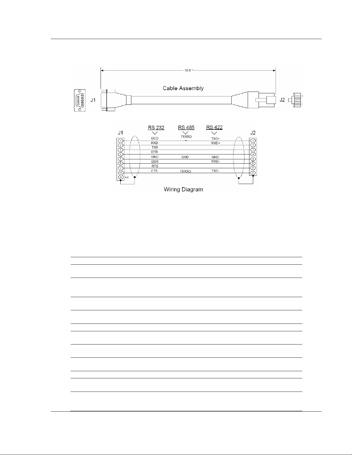
Reference MVI69-103M ♦ CompactLogix or MicroLogix Platform
IEC 60870-5-103 Master Communication Module
5.3.5 DB9 to RJ45 Adaptor (Cable 14)
5.4 MVI69-103M Status Data Area
This section contains a listing of the data contained in the MVI69-103M status
data object, configuration error word and module error codes.
5.4.1 MVI69-IEC 60870-5-103 Master Communication Module
Error/Status Data Format
Offset Parameter Description
0 Scan Count
1 to 2 Product Name
3 to 4 Revision
5 to 6 Op Sys #
7 to 8 Run Number This two-word data area contains the text values for the run number.
9 Read Blk Cnt
10 Write Blk Cnt
11 Parse Blk Cnt
12 Error Blk Cnt This word contains the total number of block transfer errors.
13 Event Msg Cnt
14
Event Msg
Overflow
ProSoft Technology, Inc. Page 95 of 131
November 3, 2008
This status value contains a counter incremented on each scan of the
module's main loop.
This two-word data area contains the text values representing the
product name. These words contain the text 'I3M5' for the MVI69
platform.
This two-word data area contains the text values for the revision
number.
This two-word data area contains the text values for the operating
system number.
This word contains the total number of block read operations
successfully executed.
This word contains the total number of block write operations
successfully executed.
This word contains the total number of write blocks successfully
parsed.
This word contains the number of event messages waiting to send to
the processor.
This word contains a value of 0 if the event message buffer has not
overflowed. If the event buffer overflows, this word will be set to a
value of 1.
Page 96

MVI69-103M ♦ CompactLogix or MicroLogix Platform Reference
IEC 60870-5-103 Master Communication Module
Offset Parameter Description
15 Session Count This word contains the number of session configured in the module.
16 Current Cmd
17 Cmd Busy Flag
18 Cmd Count
19 Cmd Delay
20 Cmd Queue
21
22 to 23 Online Status
24 CH 0 State This word contains the state machine value for channel 0.
25 Cmd Req
26 Cmd Resp
27 Cmd Err
28 Requests
29 Responses
30 Err Sent This word contains the number of error messages sent on channel 0.
31 Err Received
32 Cfg Err
33 Current Error
34 Last Error
35 CH 1 State This word contains the state machine value for channel 1.
36 Cmd Req
37 Cmd Resp
38 Cmd Err
39 Requests
Cmd Queue
Count
This word contains the index of the current command being executed
in the command list.
This word is set to zero if no command is currently being executed and
waiting on a response. If the word is set to 1, a command is currently
executing.
This word contains the count of the number of commands configured
for the module.
This word contains the command delay counter preset. There is a
fixed delay between each command to permit the module to perform
class polls on controlled stations.
This word is set to zero if the command executing is from the
command list. If the executing command is from the command queue,
the word will be set to 1.
This word contains the number of active commands in the command
queue for the module. Up to 100 commands can be buffered in this
queue. These commands are transferred from the processor to the
module using special command blocks.
This double word value contains a bit for each of the 32 potential
sessions in the module. If the bit is set for a session in the double
word, the station is online. If the bit is clear, the station is offline. Use
this value to determine if commands sent from the processor will have
a chance of succeeding.
This word contains the number of commands transferred out channel
0.
This word contains the number of command response messages
received on channel 0.
This word contains the number of command errors recognized on
channel 0.
This word contains the total number of messages transmitted on
channel 0.
This word contains the total number of messages received on channel
0.
This word contains the number of error messages received on channel
0.
This bit mapped word recognizes any configuration errors for channel
0. Refer to the configuration error word table for a definition of each
bit.
This word contains the error code for the current command executing
on channel 0.
This word contains the error code for the last error recognized on
channel 0.
This word contains the number of commands transferred out channel
1.
This word contains the number of command response messages
received on channel 1.
This word contains the number of command errors recognized on
channel 1.
This word contains the total number of messages transmitted on
channel 1.
Page 96 of 131 ProSoft Technology, Inc.
November 3, 2008
Page 97

Reference MVI69-103M ♦ CompactLogix or MicroLogix Platform
IEC 60870-5-103 Master Communication Module
Offset Parameter Description
40 Responses
41 Err Sent This word contains the number of error messages sent on channel 1.
42 Err Received
43 Cfg Err
44 Current Error
45 Last Error
46
Block Transfer
Size
This word contains the total number of messages received on channel
1.
This word contains the number of error messages received on channel
1.
This bit mapped word recognizes any configuration errors for channel
1. Refer to the configuration error word table for a definition of each
bit.
This word contains the error code for the current command executing
on channel 1.
This word contains the error code for the last error recognized on
channel 1.
Value configured by the user for block transfer size parameter.
The following table defines the contents of the configuration error word. Each bit
in the word corresponds to an error condition recognized when the module is
configured. There is a separate word for each application port. This data is
reported in the status data area previously defined.
Bit Code Description
0 0x0001 Invalid baud rate selected
1 0x0002 Invalid parity selected
2 0x0004 Received timeout set to 0
3 0x0008 Invalid Port selected for a session
4 0x0010 Invalid sector count for session
5 0x0020 Could not allocate memory for sector of a session.
6 0x0040
7 0x0080 Invalid failure delay or confirm timeout for session.
8 0x0100
9 0x0200
10 0x0400
11 0x0800
12 0x1000
13 0x2000
14 0x4000
15 0x8000
The following table lists all potential errors that can be generated by the IEC
60870-5-103 Master driver:
5.4.2 MVI69-IEC 60870-5-103 Master Communication Module Error
Codes
Error Description
51 Physical layer error - Error transmitting message
52 Physical layer error - Intercharacter timeout occurred before message fully received.
53 Physical layer error - Frame not entirely received before timeout condition.
54 Physical layer error - Invalid frame length.
101 Link layer error - Invalid checksum received
102 Link layer error - Address unknown to module
103 Link layer error - Link established
ProSoft Technology, Inc. Page 97 of 131
November 3, 2008
Page 98

MVI69-103M ♦ CompactLogix or MicroLogix Platform Reference
IEC 60870-5-103 Master Communication Module
Error Description
104 Link layer error - Link failed
105 Link layer error - Received primary
106 Link layer error - FCB error discard
107 Link layer error - FCB error repeat
108 Link layer error - Invalid start character received
109 Link layer error - Invalid second character received
110 Link layer error - Invalid ending character received
111 Link layer error - Length mismatch error
112 Link layer error - Illegal function
113 Link layer error - No confirmation received
114 Link layer error - No ACK received
115 Link layer error - Sequence unknown
116 Link layer error - Out of sequence
117 Link layer error - Remote close
118 Link layer error - Unexpected ACK
119 Link layer error - Request cancelled
201 Application layer error - Length mismatch
202 Application layer error - Address unknown
203 Application layer error - Response late
251 RBE error - Clock event buffer overflow
252 RBE error - Event buffer overflow
271 Data error - Address unknown
281 Control error - Illegal operation
282 Control error - Illegal value
283 Control error - Not selected
301 Initialization error - Database
302 Initialization error - Out of memory
401 Channel open error
501 Session error - Database
502 Session error - Configuration
601 No memory to receive message
602 Session not reserved
603 Illegal session
604 Session is reserved
605 Session is not available
701 No memory to transmit message
702 ASDU not supported
703 Duplicate request
704 Illegal sector
705 Control mode is illegal
801 Partial stop request
802 Stop request failed
901 Response timeout
902 Negative COT in response
903 Session is offline
904 Session is disabled
905 Select confirmation received, waiting to execute
906 Execute confirmation has not be received
Page 98 of 131 ProSoft Technology, Inc.
November 3, 2008
Page 99

Reference MVI69-103M ♦ CompactLogix or MicroLogix Platform
IEC 60870-5-103 Master Communication Module
5.5 Database Form
5.5.1 Form to Define Sector Database
Session Index #:
Sector Index #:
Data Type
(1, 2, 3, 4, 5 or 9)
Database Address Function Code Point Index
ProSoft Technology, Inc. Page 99 of 131
November 3, 2008
Page 100

MVI69-103M ♦ CompactLogix or MicroLogix Platform Reference
IEC 60870-5-103 Master Communication Module
Session Index #:
Sector Index #:
Data Type
(1, 2, 3, 4, 5 or 9)
Database Address Function Code Point Index
Page 100 of 131 ProSoft Technology, Inc.
November 3, 2008
 Loading...