

Page 1
MVI56E-SIE
ControlLogix Platform
Siemens Industrial Ethernet
Client Communication Module
September 6, 2012
USER MANUAL
Page 2

Your Feedback Please
We always want you to feel that you made the right decision to use our products. If you have suggestions, comments,
compliments or complaints about our products, documentation, or support, please write or call us.
How to Contact Us
ProSoft Technology
5201 Truxtun Ave., 3rd Floor
Bakersfield, CA 93309
+1 (661) 716-5100
+1 (661) 716-5101 (Fax)
www.prosoft-technology.com
support@prosoft-technology.com
Copyright © 2012 ProSoft Technology, Inc., all rights reserved.
MVI56E-SIE User Manual
September 6, 2012
ProSoft Technology ®, ProLinx ®, inRAx ®, ProTalk ®, and RadioLinx ® are Registered Trademarks of ProSoft
Technology, Inc. All other brand or product names are or may be trademarks of, and are used to identify products
and services of, their respective owners.
ProSoft Technology® Product Documentation
In an effort to conserve paper, ProSoft Technology no longer includes printed manuals with our product shipments.
User Manuals, Datasheets, Sample Ladder Files, and Configuration Files are provided on the enclosed CD-ROM in
Adobe® Acrobat Reader file format (.PDFs). These product documentation files may also be freely downloaded from
our web site: www.prosoft-technology.com
Page 3

RoHS
CE
Important Safety Information
North America Warnings
A Warning - Explosion Hazard - Substitution of components may impair suitability for Class I, Division 2.
B Warning - Explosion Hazard - When in hazardous locations, turn off power before replacing or rewiring modules.
Warning - Explosion Hazard - Do not disconnect equipment unless power has been switched off or the area is
known to be nonhazardous.
C Suitable for use in Class I, Division 2 Groups A, B, C, and D, T5 Hazardous Locations or Non-Hazardous
Locations.
ATEX Warnings and Conditions of Safe Usage
Power, Input, and Output (I/O) wiring must be in accordance with the authority having jurisdiction
A Warning - Explosion Hazard - When in hazardous locations, turn off power before replacing or wiring modules.
B Warning - Explosion Hazard - Do not disconnect equipment unless power has been switched off or the area is
known to be non-hazardous.
C These products are intended to be mounted in an IP54 enclosure. The devices shall provide external means to
prevent the rated voltage being exceeded by transient disturbances of more than 40%. This device must be used
only with ATEX certified backplanes.
D DO NOT OPEN WHEN ENERGIZED.
Electrical Ratings
Backplane Current Load: 800 mA @ 5 Vdc; 3 mA @ 24 Vdc
Operating Temperature: 0°C to 60°C (32°F to 140°F)
Storage Temperature: -40°C to 85°C (-40°F to 185°F)
Shock: 30 g operational; 50 g non-operational; Vibration: 5 g from 10 Hz to 150 Hz
Relative Humidity 5% to 95% (without condensation)
All phase conductor sizes must be at least 1.3 mm (squared) and all earth ground conductors must be at least
4mm (squared).
Markings
Page 4

Page 5

MVI56E-SIE ♦ ControlLogix Platform Contents
Client Communication Module User Manual
Contents
Your Feedback Please ........................................................................................................................ 2
How to Contact Us .............................................................................................................................. 2
ProSoft Technology® Product Documentation .................................................................................... 2
Important Safety Information ............................................................................................................... 3
Guide to the MVI56E-SIE User Manual 9
1 Start Here 11
1.1 Features .................................................................................................................. 12
1.2 System Requirements ............................................................................................. 13
1.3 Package Contents ................................................................................................... 14
1.4 Setting Jumpers ...................................................................................................... 15
1.5 Installing the Module in the Rack ............................................................................ 16
1.6 Importing the Sample Add-On Instruction ............................................................... 18
1.7 Creating a New RSLogix 5000 Project .................................................................... 19
1.7.1 Creating the Module ................................................................................................ 20
1.7.2 Importing the Add-On Instruction ............................................................................ 22
1.8 Connecting Your PC to the ControlLogix Processor ............................................... 35
1.9 Downloading the Sample Program to the Processor .............................................. 36
2 Configuring the MVI56E-SIE Module 37
2.1 Installing ProSoft Configuration Builder .................................................................. 38
2.2 Using ProSoft Configuration Builder Software ........................................................ 39
2.2.1 Setting Up the Project ............................................................................................. 39
2.2.2 Setting Module Parameters ..................................................................................... 42
2.2.3 Module ..................................................................................................................... 44
2.2.4 SIE Client x .............................................................................................................. 47
2.2.5 SIE Client x Commands .......................................................................................... 49
2.2.6 Configuration Examples .......................................................................................... 70
2.2.7 Static ARP Table ..................................................................................................... 85
2.2.8 Ethernet Configuration ............................................................................................ 86
2.3 Connecting Your PC to the Module ......................................................................... 87
2.3.1 Setting Up a Temporary IP Address ....................................................................... 87
2.4 Downloading the Project to the Module .................................................................. 91
2.4.1 Using CIPconnect to Connect to the Module .......................................................... 92
2.4.2 Using RSWho to Connect to the Module .............................................................. 102
3 Ladder Logic 103
3.1 Controller Tags ...................................................................................................... 104
3.1.1 MVI56E-SIE Controller Tags ................................................................................. 104
3.2 User-Defined Data Types (UDTs) ......................................................................... 106
3.2.1 MVI56E-SIE User-Defined Data Types ................................................................. 106
3.3 Using Controller Tags ............................................................................................ 107
ProSoft Technology, Inc. Page 5 of 168
September 6, 2012
Page 6

Contents MVI56E-SIE ♦ ControlLogix Platform
User Manual Client Communication Module
3.4 Controller Tag Overview ....................................................................................... 108
3.4.1 SIE.DATA .............................................................................................................. 108
3.4.2 SIE.CONTROL...................................................................................................... 111
3.4.3 SIE.STATUS ......................................................................................................... 111
3.4.4 SIE.UTIL ............................................................................................................... 112
4 Diagnostics and Troubleshooting 113
4.1 LED Status Indicators ........................................................................................... 114
4.1.1 Scrolling LED Status Indicators ............................................................................ 114
4.1.2 Ethernet LED Indicators ........................................................................................ 115
4.1.3 Non-Scrolling LED Status Indicators .................................................................... 115
4.1.4 Troubleshooting .................................................................................................... 116
4.1.5 Clearing a Fault Condition .................................................................................... 117
4.2 Using the Diagnostics Menu in ProSoft Configuration Builder ............................. 118
4.2.1 Connecting to the Module's Web Page ................................................................ 120
4.2.2 The Diagnostics Menu .......................................................................................... 121
4.2.3 Monitoring Module Information ............................................................................. 122
4.2.4 Monitoring Backplane Information ........................................................................ 123
4.2.5 Monitoring Database Information.......................................................................... 124
4.2.6 Monitoring SIE Client Information ......................................................................... 125
4.3 Reading Status Data from the Module ................................................................. 126
4.3.1 Status Data Definition ........................................................................................... 127
4.3.2 Configuration Error Word ...................................................................................... 129
4.3.3 Client Command Errors ........................................................................................ 130
5 Reference 133
5.1 Product Specifications .......................................................................................... 134
5.1.1 General Specifications .......................................................................................... 134
5.1.2 Functional Specifications ...................................................................................... 135
5.1.3 Hardware Specifications ....................................................................................... 135
5.2 Backplane Data Transfer ...................................................................................... 136
5.2.1 Normal Data Transfer Blocks ................................................................................ 138
5.2.2 Special Function Blocks ........................................................................................ 142
5.2.3 Client Driver .......................................................................................................... 150
5.2.4 Client Command List ............................................................................................ 151
5.3 Ethernet Cable Specifications ............................................................................... 152
5.3.1 Ethernet Cable Configuration ............................................................................... 152
5.3.2 Ethernet Performance ........................................................................................... 153
5.4 Using the Optional Add-On Instruction Rung Import ............................................ 154
5.4.1 Before Beginning ................................................................................................. 154
5.4.2 Overview ............................................................................................................... 154
5.4.3 Installing the Rung Import with Optional Add-On Instruction ................................ 155
5.4.4 Reading the Ethernet Settings from the Module................................................... 159
5.4.5 Writing the Ethernet Settings to the Module ......................................................... 161
5.4.6 Reading the Clock Value from the Module ........................................................... 163
5.4.7 Writing the Clock Value to the Module ................................................................. 164
6 Support, Service and Warranty 165
6.1 Contacting Technical Support ............................................................................... 165
6.2 Warranty Information ............................................................................................ 166
Page 6 of 168 ProSoft Technology, Inc.
September 6, 2012
Page 7

MVI56E-SIE ♦ ControlLogix Platform Contents
Client Communication Module User Manual
Index 167
ProSoft Technology, Inc. Page 7 of 168
September 6, 2012
Page 8

Contents MVI56E-SIE ♦ ControlLogix Platform
User Manual Client Communication Module
Page 8 of 168 ProSoft Technology, Inc.
September 6, 2012
Page 9

MVI56E-SIE ♦ ControlLogix Platform Guide to the MVI56E-SIE User Manual
Function
Section to Read
Details
Introduction
(Must Do)
Start Here (page 11)
This section introduces the customer to
the module. Included are: package
contents, system requirements,
hardware installation, and basic
configuration.
Diagnostic and
Troubleshooting
Diagnostics and
Troubleshooting
(page 113)
This section describes Diagnostic and
Troubleshooting procedures.
Reference
Product Specifications
Reference (page
133)
Product
Specifications (page
134)
These sections contain general
references associated with this product
and its Specifications..
Support, Service, and
Warranty
Index
Support, Service
and Warranty (page
165)
Index
This section contains Support, Service
and Warranty information.
Index of chapters.
Client Communication Module User Manual
Guide to the MVI56E-SIE User Manual
ProSoft Technology, Inc. Page 9 of 168
September 6, 2012
Page 10

Guide to the MVI56E-SIE User Manual MVI56E-SIE ♦ ControlLogix Platform
User Manual Client Communication Module
Page 10 of 168 ProSoft Technology, Inc.
September 6, 2012
Page 11

MVI56E-SIE ♦ ControlLogix Platform Start Here
In This Chapter
What's New? ......................................................................................... 12
System Requirements ........................................................................... 13
Package Contents ................................................................................. 14
Setting Jumpers .................................................................................... 15
Installing the Module in the Rack ........................................................... 16
Importing the Sample Add-On Instruction.............................................. 18
Creating a New RSLogix 5000 Project .................................................. 19
Connecting Your PC to the ControlLogix Processor .............................. 35
Downloading the Sample Program to the Processor ............................. 36
Client Communication Module User Manual
1 Start Here
To get the most benefit from this User Manual, the following skills will be needed:
Rockwell Automation® RSLogix™ software: launch the program, configure
ladder logic, and transfer the ladder logic to the processor
Microsoft Windows: install and launch programs, execute menu commands,
navigate dialog boxes, and enter data
Hardware installation and wiring: install the module, and safely connect
Siemens Industrial Ethernet and ControlLogix devices to a power source and
to the MVI56E-SIE module’s application port(s)
ProSoft Technology, Inc. Page 11 of 168
September 6, 2012
Page 12

Start Here MVI56E-SIE ♦ ControlLogix Platform
User Manual Client Communication Module
1.1 Features
.
ProSoft Configuration Builder (PCB): Windows-based software for
diagnostics, connecting via the module's Ethernet port or CIPconnect®, to
upload/download module configuration information and access
troubleshooting features and functions.
ProSoft Discovery Service (PDS): Utility software to find and display a list
of MVI56E modules on the network and to temporarily change an IP address
to connect with a module's web page.
CIPconnect-enabled: Allows PC-to-module configuration and diagnostics
from the Ethernet network through a ControlLogix 1756-ENBT EtherNet/IP™
module.
Personality Module: An industrial compact flash memory card storing the
module’s complete configuration and Ethernet settings, allowing quick and
easy replacement.
LED Scrolling Diagnostic Display: 4-character, alphanumeric display,
providing messages for status and alarm data, and for processor and network
communication status.
Page 12 of 168 ProSoft Technology, Inc.
September 6, 2012
Page 13

MVI56E-SIE ♦ ControlLogix Platform Start Here
Client Communication Module User Manual
1.2 System Requirements
The MVI56E-SIE module requires the following minimum hardware and software
components:
Rockwell Automation ControlLogix® processor (firmware version 16 or
higher), with compatible power supply, and one free slot in the rack for the
MVI56E-SIE module. The module requires 800 mA of available 5 Vdc power
Rockwell Automation RSLogix 5000 programming software
o Version 16 or higher required for Add-On Instruction
Rockwell Automation RSLinx® communication software version 2.51 or higher
ProSoft Configuration Builder (PCB) (included)
ProSoft Discovery Service (PDS) (included in PCB)
Pentium® II 450 MHz minimum. Pentium III 733 MHz (or better)
recommended
Supported operating systems:
o Microsoft Windows
o Microsoft Windows XP Professional with Service Pack 1 or 2
o Microsoft Windows 2000 Professional with Service Pack 1, 2, or 3
o Microsoft Windows Server 2003
o Microsoft Windows 7
128 Mbytes of RAM minimum, 256 Mbytes of RAM recommended
100 Mbytes of free hard disk space (or more based on application
requirements)
256-color VGA graphics adapter, 800 x 600 minimum resolution (True Color
1024 768 recommended)
CD-ROM drive/DVD drive
®
Vista
Note: The Hardware and Operating System requirements in this list are the
minimum recommended to install and run software provided by ProSoft
Technology®. Other third party applications may have different minimum
requirements. Refer to the documentation for any third party applications for
system requirements.
Note: The module can be installed in a local or remote rack. For remote rack
installation, the module requires EtherNet/IP or ControlNet communication with
the processor.
ProSoft Technology, Inc. Page 13 of 168
September 6, 2012
Page 14

Start Here MVI56E-SIE ♦ ControlLogix Platform
Qty.
Part Name
Part Number
Part Description
1
MVI56E-SIE Module
MVI56E-SIE
Siemens Industrial Ethernet Client
Communication Module
1
Cable
RL-CBL025
5-foot Ethernet Straight-Through Cable
(Gray)
1
ProSoft Solutions CD
OR
ProSoft Solutions
DVD
CD-001
DVD-001
Contains configuration tools for the
MVI56E-SIE module
User Manual Client Communication Module
1.3 Package Contents
The following components are included with your MVI56E-SIE module, and are
all required for installation and configuration.
Important: Before beginning the installation, please verify that all of the following
items are present.
If any of these components are missing, please contact ProSoft Technology
Support for replacement parts.
Page 14 of 168 ProSoft Technology, Inc.
September 6, 2012
Page 15
MVI56E-SIE ♦ ControlLogix Platform Start Here
Client Communication Module User Manual
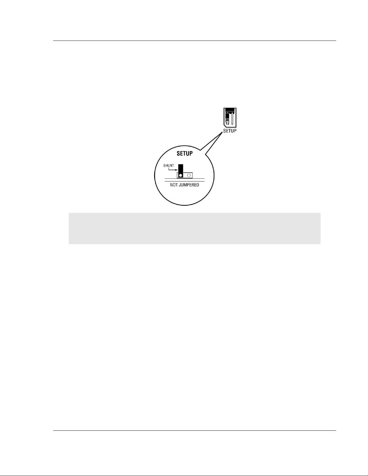
1.4 Setting Jumpers
The Setup Jumper acts as "write protection" for the module’s flash memory. In
"write protected" mode, the Setup pins are not connected, and the module’s
firmware cannot be overwritten. Do not jumper the Setup pins together unless
you are directed to do so by ProSoft Technical Support.
The following illustration shows the MVI56E-SIE jumper configuration.
Note: If the module is being installed in a remote rack, the Setup pins can be left
jumpered. That way, the module’s firmware can be updated without requiring
physical access to the module.
ProSoft Technology, Inc. Page 15 of 168
September 6, 2012
Page 16
Start Here MVI56E-SIE ♦ ControlLogix Platform
User Manual Client Communication Module
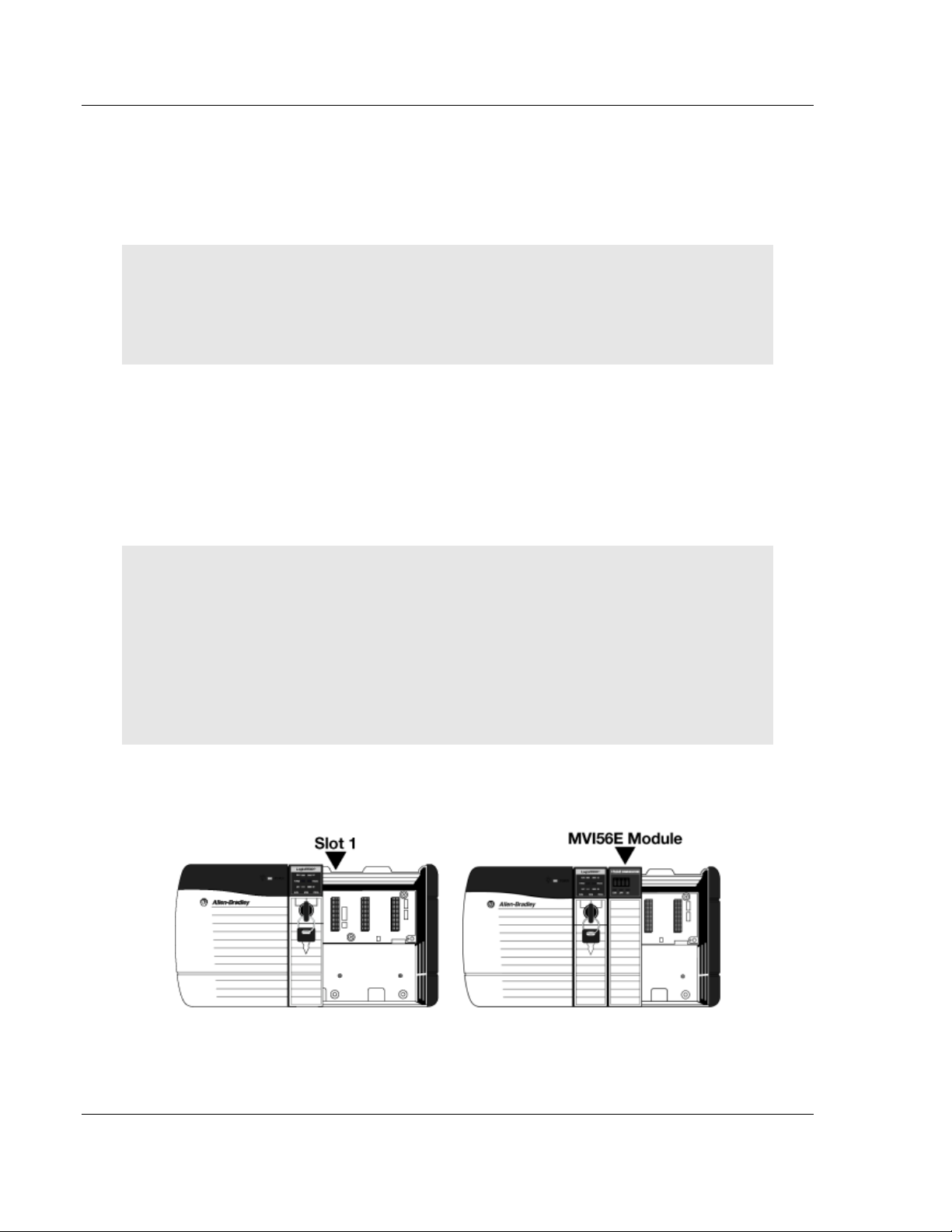
1.5 Installing the Module in the Rack
If the ControlLogix processor and power supply have not already been installed
and configured, please do so before installing the MVI56E-SIE module. Refer to
the Rockwell Automation product documentation for installation instructions.
Warning: All safety instructions must be followed when installing this or any
other electronic devices. Failure to follow safety procedures could result in
damage to hardware or data, or even serious injury or death to personnel. Refer
to the documentation for each device that will be connected to verify that
suitable safety procedures are in place before installing or servicing the device.
After the placement of the jumpers has been checked, insert the MVI56E-SIE
into the ControlLogix chassis. Use the same technique recommended by
Rockwell Automation to remove and install ControlLogix modules.
ControlLogix system components can be installed or removed while chassis
power is applied and the system is operating. However, please note the following
warning.
Warning: When the module is inserted or removed while backplane power is on,
an electrical arc can occur. An electrical arc can cause personal injury or
property damage by sending an erroneous signal to the system’s actuators. This
can cause unintended machine motion or loss of process control. Electrical arcs
may also cause an explosion when they happen in a hazardous environment.
Verify that power is removed or the area is non-hazardous before proceeding.
Repeated electrical arcing causes excessive wear to contacts on both the
module and its mating connector. Worn contacts may create electrical resistance
that can affect module operation.
1 Align the module with the top and bottom guides, and then slide it into the
rack until the module is firmly against the backplane connector.
2 With a firm, steady push, snap the module into place.
3 Check that the holding clips on the top and bottom of the module are securely
in the locking holes of the rack.
Page 16 of 168 ProSoft Technology, Inc.
September 6, 2012
Page 17

MVI56E-SIE ♦ ControlLogix Platform Start Here
Client Communication Module User Manual
4 Make a note of the slot location. The slot in which the module is installed in
must be indentified in order for the sample program to work correctly. Slot
numbers are identified on the green circuit board (backplane) of the
ControlLogix rack.
5 Turn power ON.
Note: If the module is inserted improperly, the system may stop working or may
behave unpredictably.
ProSoft Technology, Inc. Page 17 of 168
September 6, 2012
Page 18

Start Here MVI56E-SIE ♦ ControlLogix Platform
File Name
Description
MVI56ESIE_AddOn_Rung_v1_0.L5X
L5X file containing Add-On Instruction, user defined
data types, controller tags and ladder logic required
to configure the MVI56E-SIE module
MVI56ESIE_Optional_Rung_v1_0.L5X
Optional L5X file containing additional Add-On
Instruction with logic for changing Ethernet
configuration and clock settings.
User Manual Client Communication Module
1.6 Importing the Sample Add-On Instruction
Note: This section only applies if the processor is using RSLogix 5000 version 16
or higher. If an earlier version is installed, please contact ProSoft Technology for
more information.
Before You Begin
Two Add-On Instructions are provided for the MVI56E-SIE module. The first is
required for setting up the module; the second is optional.
Copy the files from the ProSoft Solutions CD-ROM or Prosoft Solutions DVD or
download them from www.prosoft-technology.com. Save them to a convenient
location in your PC, such as Desktop or My Documents.
Page 18 of 168 ProSoft Technology, Inc.
September 6, 2012
Page 19
MVI56E-SIE ♦ ControlLogix Platform Start Here
Client Communication Module User Manual
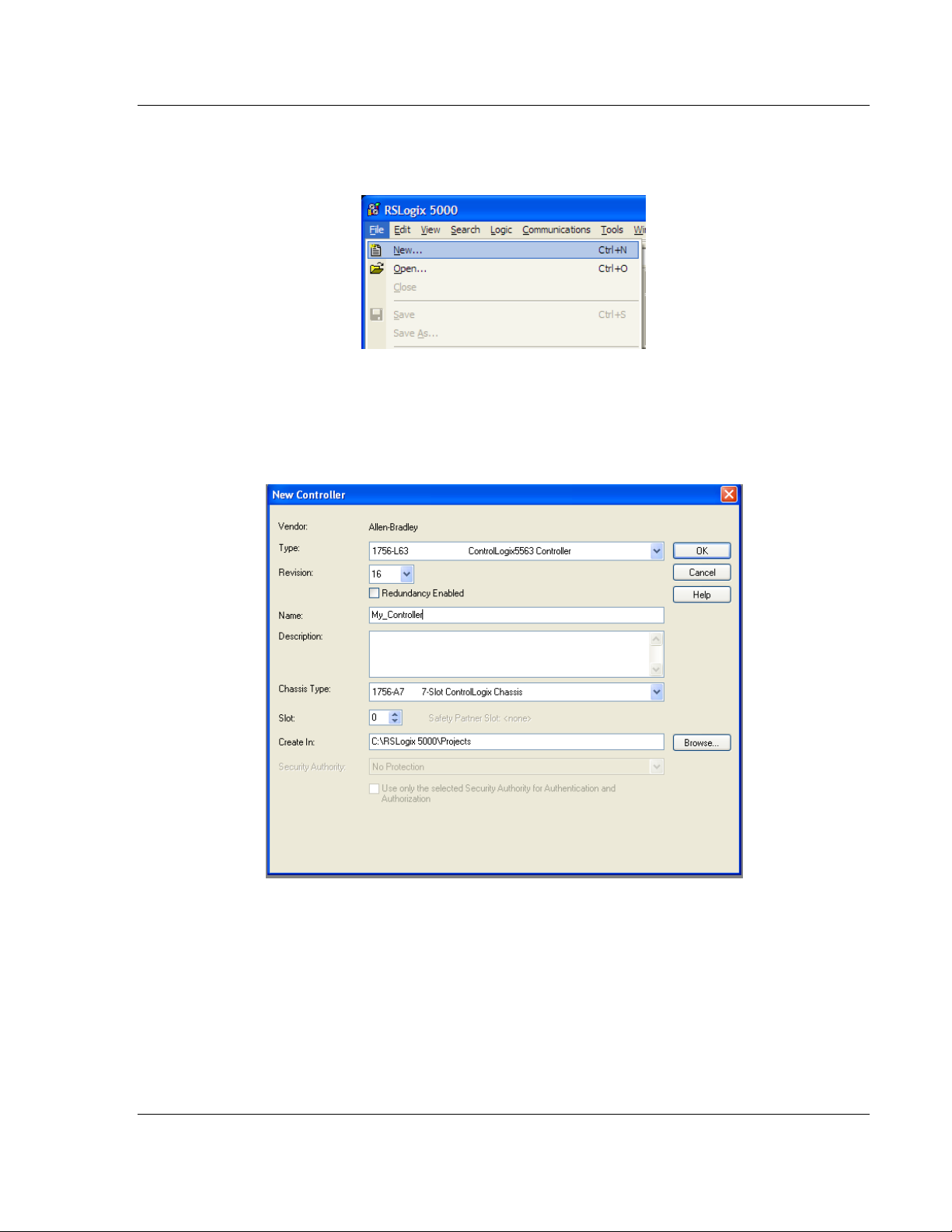
1.7 Creating a New RSLogix 5000 Project
1 Open the FILE menu, and then choose NEW.
2 Select the ControlLogix controller model.
3 Select REVISION 16.
4 Enter a name forthe controller, such as My_Controller.
5 Select theControlLogix chassis type.
6 Select SLOT 0 for the controller.
ProSoft Technology, Inc. Page 19 of 168
September 6, 2012
Page 20
Start Here MVI56E-SIE ♦ ControlLogix Platform
User Manual Client Communication Module
1.7.1 Creating the Module
1 Add the MVI56E-SIE module to the project.
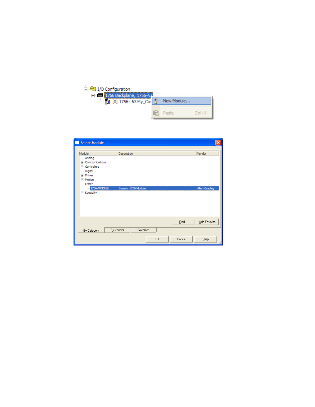
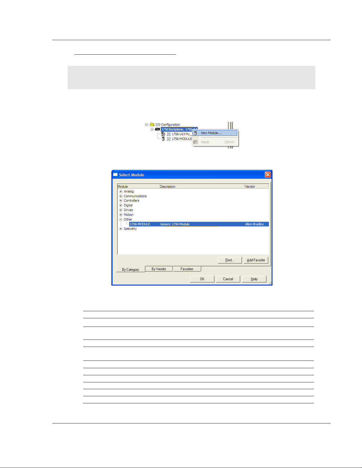
In the Controller Organization window, select I/O CONFIGURATION and click
the right mouse button to open a shortcut menu. On the shortcut menu,
choose NEW MODULE.
This action opens the Select Module dialog box.
2 Select the 1756-MODULE (GENERIC 1756 MODULE) from the list and click OK.
This action opens the New Module dialog box.
Page 20 of 168 ProSoft Technology, Inc.
September 6, 2012
Page 21
MVI56E-SIE ♦ ControlLogix Platform Start Here
Parameter
Value
Name
Enter a module identification string. Example: SIE
Description
Enter a description for the module. Example: SIEMENS
INDUSTRIAL ETHERNET CLIENT COMMUNICATION MODULE
Comm Format
Select DATA-INT.
Slot
Enter the slot number in the rack where the MVI56E-SIE
module is located.
Input Assembly Instance
1
Input Size
250
Output Assembly Instance
2
Output Size
248
Configuration Assembly Instance
4
Configuration Size
0
Client Communication Module User Manual
3 In the New Module dialog box, enter the following values.
Important: The Comm Format DATA – INTmust be selected in the dialog box,
otherwise the module will not communicate over the backplane of the
ControlLogix rack.
4 Click OK to continue.
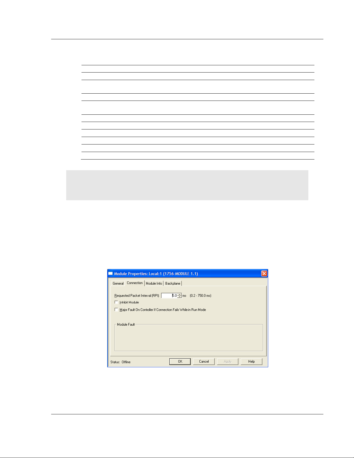
5 Edit the Module Properties. Select the Requested Packet Interval value for
scanning the I/O on the module. This value represents the minimum
frequency at which the module will handle scheduled events. This value
should not be set to less than 1 millisecond. The default value is 5
milliseconds. Values between 1 and 10 milliseconds should work with most
applications.
6 Save the module.
ProSoft Technology, Inc. Page 21 of 168
September 6, 2012
Page 22
Start Here MVI56E-SIE ♦ ControlLogix Platform
User Manual Client Communication Module
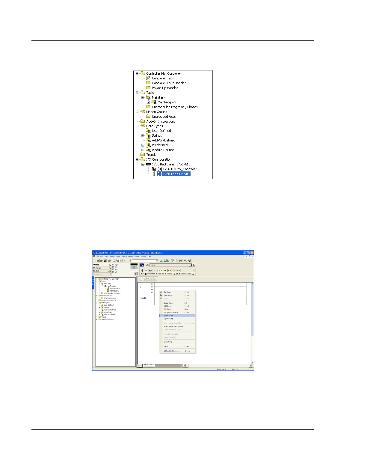
Click OK to close the dialog box. Notice that the module now appears in the
Controller Organization window.
1.7.2 Importing the Add-On Instruction
1 In the Controller Organization window, expand the TASKS folder and
subfolder until the MAINPROGRAM folder is reached.
2 In the MAINPROGRAM folder, double-click to open the MAINROUTINE ladder.
3 Select an empty rung in the new routine, and then click the right mouse
button to open a shortcut menu. On the shortcut menu, choose IMPORT RUNG.
Page 22 of 168 ProSoft Technology, Inc.
September 6, 2012
Page 23
MVI56E-SIE ♦ ControlLogix Platform Start Here
Client Communication Module User Manual
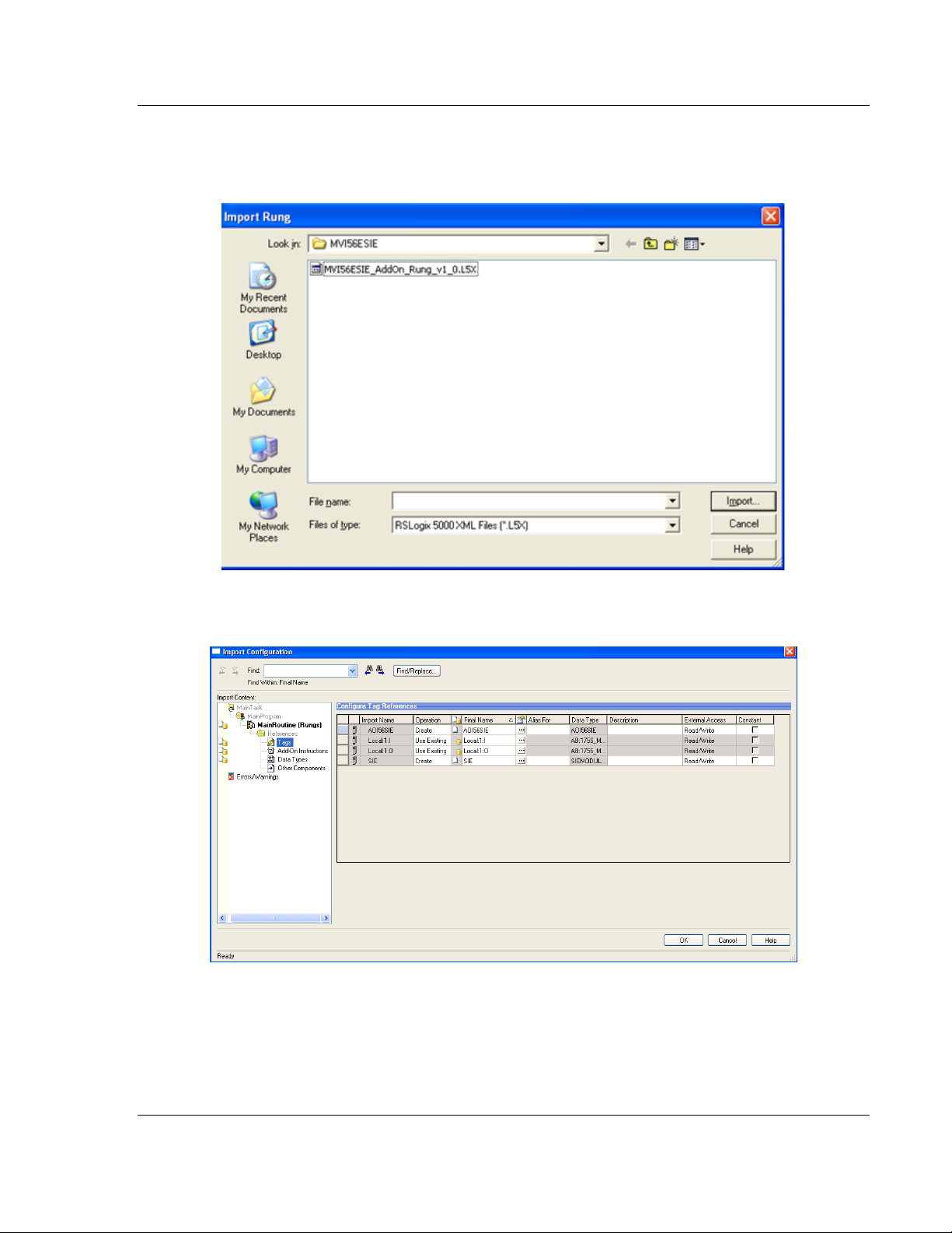
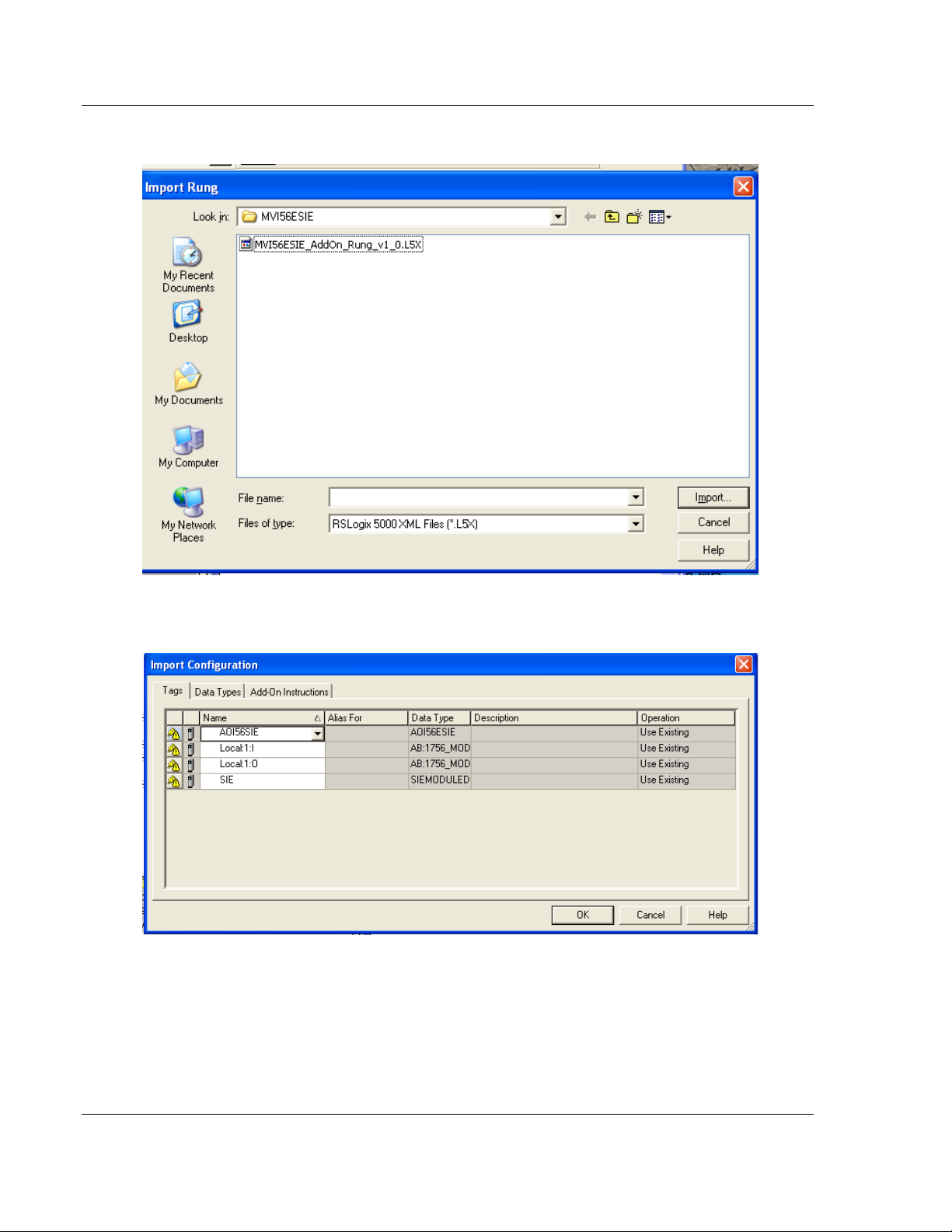
4 Navigate to the location on the PC where the Add-On Instruction was saved
(for example, My Documents or Desktop). Select the
MVI56ESIE_ADDON_RUNG_V1_0.L5X file.
This action opens the Import Configuration dialog box. Clicking on Tags
Reference will show the controller tags that will be created.
5 If the module is being used in a different slot (or remote rack), select the
correct connection input and output variables that define the path to the
module. If the module is located in Slot 1 of the local rack, this step is not
required.
ProSoft Technology, Inc. Page 23 of 168
September 6, 2012
Page 24
Start Here MVI56E-SIE ♦ ControlLogix Platform
User Manual Client Communication Module
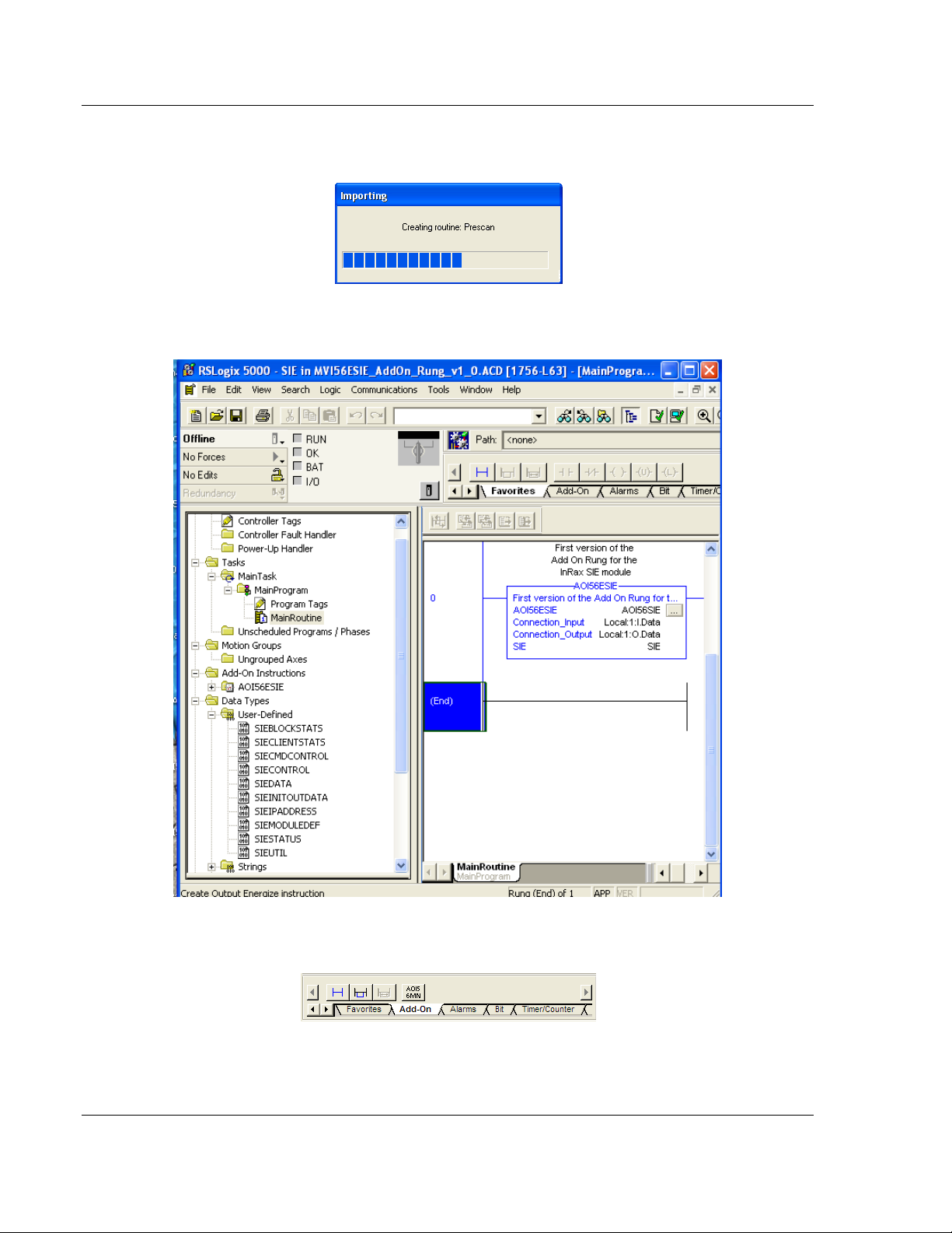
6 Click OK to confirm the import. RSLogix will indicate that the import is in
progress:
When the import is completed, the new rung with the Add-On Instruction will
be visible as shown in the following illustration.
The procedure has also imported new user-defined data types, data objects
and the Add-On Instruction for your project.
7 Save the application and then download the sample ladder logic to the
processor.
Page 24 of 168 ProSoft Technology, Inc.
September 6, 2012
Page 25
MVI56E-SIE ♦ ControlLogix Platform Start Here
Parameter
Value
Name
Enter a module identification string. Example: SIE_2.
Description
Enter a description for the module. Example: SIEMENS
INDUSTRIAL ETHERNET CLIENT COMMUNICATION MODULE
Comm Format
Select DATA-INT.
Slot
Enter the slot number in the rack where the MVI56E-SIE
module is located.
Input Assembly Instance
1
Input Size
250
Output Assembly Instance
2
Output Size
248
Configuration Assembly Instance
4
Configuration Size
0
Client Communication Module User Manual
Adding Multiple Modules (Optional)
Important: If the application requires more than one MVI56-SIE module in the
same project, follow the steps below.
1 In the I/O CONFIGURATION folder, click the right mouse button to open a
shortcut menu, and then choose NEW MODULE.
2 Select 1756-MODULE.
3 Fill the module properties as follows:
ProSoft Technology, Inc. Page 25 of 168
September 6, 2012
Page 26
Start Here MVI56E-SIE ♦ ControlLogix Platform
User Manual Client Communication Module
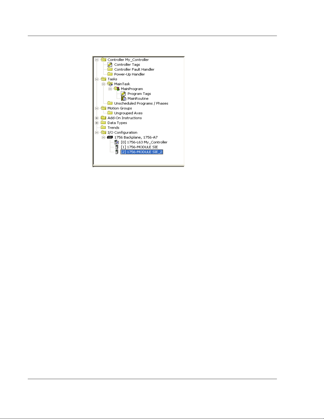
4 Click OK to confirm. The new module is now visible:
5 Expand the TASKS folder, and then expand the MAINTASK folder.
6 In the MAINPROGRAM folder, double-click to open the MAINROUTINE ladder.
Page 26 of 168 ProSoft Technology, Inc.
September 6, 2012
Page 27
MVI56E-SIE ♦ ControlLogix Platform Start Here
Client Communication Module User Manual
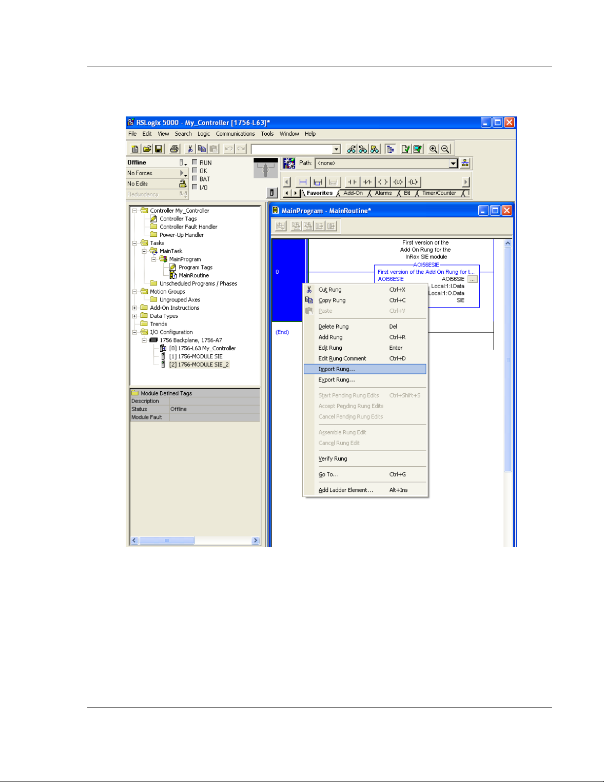
7 Select an empty rung in the routine, and then click the right mouse button to
open a shortcut menu. On the shortcut menu, choose IMPORT RUNG.
ProSoft Technology, Inc. Page 27 of 168
September 6, 2012
Page 28
Start Here MVI56E-SIE ♦ ControlLogix Platform
User Manual Client Communication Module
8 Select the MVI56ESIE_ADDON_RUNG_V1_0.L5X file, and then click IMPORT.
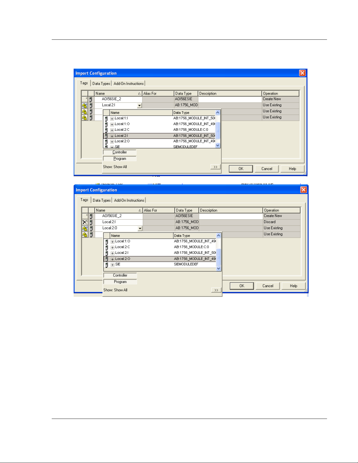
9 This action opens the Import Configuration window, which shows the tags
that will be imported.
Page 28 of 168 ProSoft Technology, Inc.
September 6, 2012
Page 29
MVI56E-SIE ♦ ControlLogix Platform Start Here
Client Communication Module User Manual
10 Associate the I/O connection variables to the correct module. The default
values are Local:1:I and Local:1:O so these require change.
ProSoft Technology, Inc. Page 29 of 168
September 6, 2012
Page 30
Start Here MVI56E-SIE ♦ ControlLogix Platform
User Manual Client Communication Module
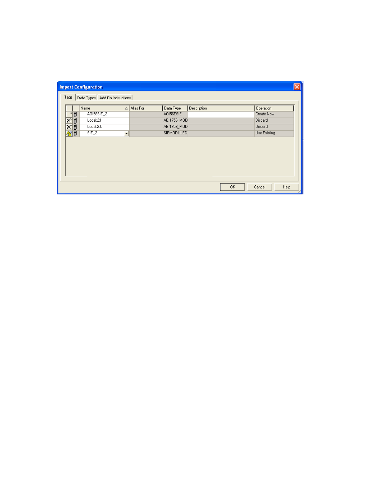
11 Change the default tags SIE and AOI56SIE to avoid conflict with existing
tags. In this step, you should append a string to the default tag names, such
as "_2", as shown in the following illustration.
Page 30 of 168 ProSoft Technology, Inc.
September 6, 2012
Page 31

MVI56E-SIE ♦ ControlLogix Platform Start Here
Client Communication Module User Manual
12 Click OK to confirm.
The setup procedure is now complete. Save the project and download the
application to your ControlLogix processor.
ProSoft Technology, Inc. Page 31 of 168
September 6, 2012
Page 32

Start Here MVI56E-SIE ♦ ControlLogix Platform
User Manual Client Communication Module
Adjusting the Input and Output Array Sizes
The module’s internal database is divided into two user-configurable areas:
Read Data
Write Data
The Read Data is moved from the module to the processor, while the Write Data
is moved from the processor to the module.
The MVI56E-SIE Add-On Instruction rung is configured for 600 registers of Read
Data and 600 registers of Write Data, which is sufficient for most applications.
However, you can configure the sizes of these data areas to meet the needs of
your application.
Important: Because the module pages data in blocks of 200 registers at a time,
you should configure your user data areas in multiples of 200 registers.
Caution: When the array size is changed, RSLogix may reset the SIE tags to
zero. To avoid data loss, be sure to save the settings before continuing.
1 In the Controller Organizer pane, expand the Data Types and User-Defined
folders, then double-click SIEDATA.
Page 32 of 168 ProSoft Technology, Inc.
September 6, 2012
Page 33

MVI56E-SIE ♦ ControlLogix Platform Start Here
Client Communication Module User Manual
2 In the Data Type: SIEDATA dialog box, change the data type designation of
the ReadData array to the desired value. In the example below, it was
changed from INT[600] to INT[1000]. Click APPLY.
Note: If RSLogix resets your data values, refer to the backup copy of your
program to re-enter your configuration parameters.
3 In ProSoft Configuration Builder, expand the Module icon in the tree view and
double-click MODULE to open an Edit window. Change the READ REGISTER
COUNT to contain the number of words for your Read Data area.
ProSoft Technology, Inc. Page 33 of 168
September 6, 2012
Page 34

Start Here MVI56E-SIE ♦ ControlLogix Platform
User Manual Client Communication Module
4 To modify the WriteData array, follow the above steps, substituting Write for
Read.
5 Save and download the configuration to the module and reboot.
Make sure that the ReadData and WriteData arrays do not overlap in the module
memory. For example, if your application requires 2000 words of Write Data
starting at register 0, then your Read Register Start parameter must be set to a
value of 2000 or greater.
Page 34 of 168 ProSoft Technology, Inc.
September 6, 2012
Page 35

MVI56E-SIE ♦ ControlLogix Platform Start Here
Client Communication Module User Manual
1.8 Connecting Your PC to the ControlLogix Processor
There are several ways to establish communication between your PC and the
ControlLogix processor. The following steps show how to establish
communication through the serial interface. It is not mandatory to use the
processor's serial interface. The processor may be accessed through whatever
network interface is available on the system. Refer to theRockwell Automation
documentation for information on other connection methods.
1 Connect the right-angle connector end of the cable to the controller at the
communications port.
2 Connect the straight connector end of the cable to the serial port on the
computer.
ProSoft Technology, Inc. Page 35 of 168
September 6, 2012
Page 36

Start Here MVI56E-SIE ♦ ControlLogix Platform
User Manual Client Communication Module
1.9 Downloading the Sample Program to the Processor
Note: The key switch on the front of the ControlLogix processor must be in the
REM or PROG position.
1 If the processor is not already online, open the Communications menu, and
then choose DOWNLOAD. RSLogix 5000 will establish communication with the
processor. Download does not have to occur using the processor's serial
port, as shown here. Download may be achieved through any available
network connection.
2 When communication is established, RSLogix 5000 will open a confirmation
dialog box. Click the DOWNLOAD button to transfer the sample program to the
processor.
3 RSLogix 5000 will compile the program and transfer it to the processor. This
process may take a few minutes.
4 When the download is complete, RSLogix 5000 will open another
confirmation dialog box. If the key switch is in the REM position, click OK to
switch the processor from PROGRAM mode to RUN mode.
Note: If an error message is recieved during these steps, refer to the RSLogix
documentation to interpret and correct the error.
Page 36 of 168 ProSoft Technology, Inc.
September 6, 2012
Page 37

MVI56E-SIE ♦ ControlLogix Platform Configuring the MVI56E-SIE Module
In This Chapter
Installing ProSoft Configuration Builder ................................................. 38
Using ProSoft Configuration Builder Software ....................................... 39
Connecting Your PC to the Module ....................................................... 87
Downloading the Project to the Module ................................................. 91
Client Communication Module User Manual
2 Configuring the MVI56E-SIE Module
ProSoft Technology, Inc. Page 37 of 168
September 6, 2012
Page 38

Configuring the MVI56E-SIE Module MVI56E-SIE ♦ ControlLogix Platform
User Manual Client Communication Module
2.1 Installing ProSoft Configuration Builder
To install ProSoft Configuration Builder from the CD-ROM
1 Insert the ProSoft Solutions CD-ROM or the Prosoft Solutions DVD into the
CD/DVD drive of the PC. Wait for the startup screen to appear.
2 On the startup screen, click INSTALL PROSOFT CONFIGURATION BUILDER. This
action starts the installation wizard for ProSoft Configuration Builder.
3 Click NEXT on each page of the installation wizard. Click FINISH on the last
page of the wizard.
Page 38 of 168 ProSoft Technology, Inc.
September 6, 2012
Page 39

MVI56E-SIE ♦ ControlLogix Platform Configuring the MVI56E-SIE Module
Client Communication Module User Manual
2.2 Using ProSoft Configuration Builder Software
ProSoft Configuration Builder (PCB) provides a convenient way to manage
module configuration files customized to meet application needs. PCB is not
only a powerful solution for new configuration files, but also allows importing of
information from previously installed (known working) configurations to new
projects.
Note: During startup and initialization, the MVI56E-SIE module receives its
protocol and backplane configuration information from the installed Personality
Module (Compact Flash). Use ProSoft Configuration Builder to configure module
settings and to download changes to the Personality Module.
2.2.1 Setting Up the Project
To begin, start PROSOFT CONFIGURATION BUILDER (PCB).
ProSoft Technology, Inc. Page 39 of 168
September 6, 2012
Page 40

Configuring the MVI56E-SIE Module MVI56E-SIE ♦ ControlLogix Platform
User Manual Client Communication Module
If other Windows configuration tools have been used before, the screen layout
will be found to be familiar. PCB’s window consists of a tree view on the left, and
an information pane and a configuration pane on the right side of the window.
When first starting PCB, the tree view consists of folders for Default Project and
Default Location, with a Default Module in the Default Location folder. The
following illustration shows the PCB window with a new project.
The first task is to add the MVI56E-SIE module to the project.
1 Use the mouse to select DEFAULT MODULE in the tree view, and then click the
right mouse button to open a shortcut menu.
Page 40 of 168 ProSoft Technology, Inc.
September 6, 2012
Page 41

MVI56E-SIE ♦ ControlLogix Platform Configuring the MVI56E-SIE Module
Client Communication Module User Manual
2 On the shortcut menu, select CHOOSE MODULE TYPE. This action opens the
Choose Module Type dialog box.
3 In the Product Line Filter area of the dialog box, select MVI56E. In the Select
Module Type dropdown list, select MVI56E-SIE, and then click OK to save
the settings and return to the ProSoft Configuration Builder window.
ProSoft Technology, Inc. Page 41 of 168
September 6, 2012
Page 42

Configuring the MVI56E-SIE Module MVI56E-SIE ♦ ControlLogix Platform
User Manual Client Communication Module
2.2.2 Setting Module Parameters
Notice that the contents of the information pane and the configuration pane
changed when the MVI56E-SIE module was added to the project.
At this time, the Default Project and Default Location folders may be renamed in
the tree view.
Renaming an Object
1 Select the object, and then click the right mouse button to open a shortcut
menu. From the shortcut menu, choose RENAME.
2 Type the name to assign to the object.
3 Click away from the object to save the new name.
Configuring Module Parameters
1 Click the [+] sign next to the module icon to expand module information.
2 Click the [+] sign next to any icon to view module information and
configuration options.
3 Double-click any icon to open an Edit dialog box.
4 To edit a parameter, select the parameter in the left pane and make the
changes in the right pane.
5 Click OK to save the changes.
Page 42 of 168 ProSoft Technology, Inc.
September 6, 2012
Page 43

MVI56E-SIE ♦ ControlLogix Platform Configuring the MVI56E-SIE Module
Client Communication Module User Manual
Printing a Configuration File
1 Select the module icon, and then click the right mouse button to open a
shortcut menu.
2 On the shortcut menu, choose VIEW CONFIGURATION. This action opens the
View Configuration window.
3 In the View Configuration window, open the FILE menu, and choose PRINT.
This action opens the Print dialog box.
4 In the Print dialog box, choose the printer to use from the drop-down list,
select printing options, and then click OK.
ProSoft Technology, Inc. Page 43 of 168
September 6, 2012
Page 44

Configuring the MVI56E-SIE Module MVI56E-SIE ♦ ControlLogix Platform
User Manual Client Communication Module
2.2.3 Module
This section of the configuration describes the database setup and module-level
parameters.
Backplane Error/Status Pointer
1 to 4955
This parameter sets the address in the internal database where the backplane
error/status data will be placed. If you want the error/status data to be moved to
the processor and placed into the ReadData array, the value entered should be a
module memory address in the Read Data area. If the value is set to -1, the
error/status data will not be stored in the module's internal database and will not
be transferred to the processor's ReadData array.
Enabling the Error/Status Pointer is optional. The error/status data is routinely
returned as part of the input image, which is continually being transferred from
the module to the processor. For more information, see Normal Data Transfer
Blocks (page 138).
Read Register Start
0 to 4999
This parameter specifies the start of the Read Data area in module memory.
Data in this area will be transferred from the module to the processor.
Note: Total user database memory space is limited to the first 5000 registers of
module memory, addresses 0 through 4999. Therefore, the practical limit for this
parameter is 4999 minus the value entered for Read Register Count, so that the
Read Data Area does not try to extend above address 4999. Read Data and
Write Data Areas must be configured to occupy separate address ranges in
module memory and should not be allowed to overlap.
Read Register Count
0 to 5000
This parameter specifies the size of the Read Data area of module memory and
the number of registers to transfer from this area to the processor, up to a
maximum of 5000 words.
Note: Total Read Register Count and Write Register Count cannot exceed 5000
total registers. Read Data and Write Data Areas must be configured to occupy
separate address ranges in module memory and should not be allowed to
overlap.
Page 44 of 168 ProSoft Technology, Inc.
September 6, 2012
Page 45

MVI56E-SIE ♦ ControlLogix Platform Configuring the MVI56E-SIE Module
Client Communication Module User Manual
Write Register Start
0 to 4999
This parameter specifies the start of the Write Data area in module memory.
Data in this area will be transferred in from the processor.
Note: Total user database memory space is limited to the first 5000 registers of
module memory, addresses 0 through 4999. Therefore, the practical limit for this
parameter is 4999 minus the value entered for Write Register Count, so that the
Write Data Area does not try to extend above address 4999. Read Data and
Write Data Areas must be configured to occupy separate address ranges in
module memory and should not be allowed to overlap.
Write Register Count
0 to 5000
This parameter specifies the size of the Write Data area of module memory and
the number of registers to transfer from the processor to this memory area, up to
a maximum value of 5000 words.
Note: Total Read Register Count and Write Register Count cannot exceed 5000
total registers. Read Data and Write Data Areas must be configured to occupy
separate address ranges in module memory and should not be allowed to
overlap.
Failure Flag Count
If this value is greater than zero the protocol communication will be interrupted
once a backplane failure is detected, or communication with the processor fails.
A value of zero will disable this feature.
Initialize Output Data
0 = No, 1 = Yes
This parameter is used to determine if the output data for the module should be
initialized with values from the processor. If the value is set to 0, the output data
will be initialized to 0. If the value is set to 1, the data will be initialized with data
from the processor. Use of this option requires associated ladder logic to pass
the data from the processor to the module.
ProSoft Technology, Inc. Page 45 of 168
September 6, 2012
Page 46

Configuring the MVI56E-SIE Module MVI56E-SIE ♦ ControlLogix Platform
User Manual Client Communication Module
Duplex/Speed Code
0, 1, 2, 3 or 4
This parameter allows the module to use a specific duplex and speed setting.
Value = 1: Half duplex, 10 MB speed
Value = 2: Full duplex, 10 MB speed
Value = 3: Half duplex, 100 MB speed
Value = 4: Full duplex, 100 MB speed
Value = 0: Auto-negotiate
Auto-negotiate is the default value.
Page 46 of 168 ProSoft Technology, Inc.
September 6, 2012
Page 47

MVI56E-SIE ♦ ControlLogix Platform Configuring the MVI56E-SIE Module
Client Communication Module User Manual
2.2.4 SIE Client x
This section defines general configuration for the SIE Client (Master).
Client Error/Status Pointer
-1 to 4990
This parameter sets the address in the internal database where the Client
error/status data will be placed. If the error/status data needs to be moved to the
processor and placed into the ReadData array, the value entered should be a
module memory address in the Read Data area. If the value is set to -1, the
error/status data will not be stored in the module's internal database and will not
be transferred to the processor's ReadData array.
Enabling the Error/Status Pointer is optional. Alternatively, the error/status data
for a specific Client can be requested by the processor and returned in a special
Client Status block. For more information, see Client Status Blocks (page 143).
Command Error Pointer
-1 to 4999
This parameter sets the address in the internal database where the Command
Error List data will be placed. If you want the Command Error List data to be
moved to the processor and placed into the ReadData array, the value entered
should be a module memory address in the Read Data area. If the value is set to
-1, the Command Error List data will not be stored in the module's internal
database and will not be transferred to the processor's ReadData array.
Enabling the Command Error Pointer is optional. Alternatively, the Command
Error List data for a specific Client can be requested by the processor and
returned in a special Client Status block. For more information, see Client Status
Blocks (page 143).
Minimum Command Delay
0 to 65535 milliseconds
This parameter specifies the number of milliseconds to wait between the initial
issuances of a command. This parameter can be used to delay all commands
sent to servers to avoid "flooding" commands on the network. This parameter
does not affect retries of a command as they will be issued when failure is
recognized.
Response Timeout
0 to 65535 milliseconds
This parameter specifies the time in milliseconds that a Client will wait before re-
transmitting a command if no response is received from the addressed server.
The value to use depends on the type of communication network used, and the
expected response time of the slowest device on the network.
ProSoft Technology, Inc. Page 47 of 168
September 6, 2012
Page 48

Configuring the MVI56E-SIE Module MVI56E-SIE ♦ ControlLogix Platform
User Manual Client Communication Module
Retry Count
0 to 10
This parameter specifies the number of times a command will be retried if it fails.
Command Error Delay
0 to 300
This parameter specifies the number of 100 millisecond intervals to turn off a
command in the error list after an error is recognized for the command. If this
parameter is set to 0, there will be no delay.
Page 48 of 168 ProSoft Technology, Inc.
September 6, 2012
Page 49

MVI56E-SIE ♦ ControlLogix Platform Configuring the MVI56E-SIE Module
Client Communication Module User Manual
2.2.5 SIE Client x Commands
The SIE Client x Commands section of the configuration sets the Siemens
Industrial Ethernet Client command list. This command list polls Siemens
Industrial Ethernet server devices attached to the Siemens Industrial Ethernet
Client port. The module supports numerous commands. This permits the module
to interface with a wide variety of Siemens Industrial Ethernet protocol devices.
The function codes used for each command are those specified in the Siemens
Industrial Ethernet protocol. Each command list record has the same format. The
first part of the record contains the information relating to the MVI56E-SIE
communication module, and the second part contains information required to
interface to the Siemens Industrial Ethernet server device.
Command List Overview
In order to interface the module with Siemens Industrial Ethernet server devices,
a command list must be constructed. The commands in the list specify the server
device to be addressed, the function to be performed (read or write), the data
area in the device to interface with, and the registers in the internal database to
be associated with the device data. The Client command list supports up to 16
commands.
The command list is processed from top (command #1) to bottom. A poll interval
parameter is associated with each command to specify a minimum delay time in
tenths of a second between the issuances of a command. If the user specifies a
value of 10 for the parameter, the command will be executed no more frequently
than every 1 second.
Commands Supported by the Module
The format of each command in the list depends on the Siemens Industrial
Ethernet Function Code being executed.
The following table lists the functions supported by the module. The type of
functions that will be supported will also depend on the server device and what it
can support. Below are examples of S7-200, S7-300 and S7-1200 functions that
are supported using MVI56E-SIE module.
ProSoft Technology, Inc. Page 49 of 168
September 6, 2012
Page 50

Configuring the MVI56E-SIE Module MVI56E-SIE ♦ ControlLogix Platform
Address Type
Function
Data Type
DB
READ
BOOL
Write
BOOL
READ
BYTE
Write
BYTE
READ
DINT
Write
DINT
READ
REAL
Write
REAL
READ
INT
Write
INT
READ
TIME
Write
TIME
READ
COUNT
Write
COUNT
Address Type
Function
Data Type
Timer
READ
TIME
Address Type
Function
Data Type
Counter
READ
Count
Address Type
Function
Data Type
Flag
READ
BOOL
Write
BOOL
READ
BYTE
Write
BYTE
READ
DINT
Write
DINT
READ
REAL
Write
REAL
READ
INT
Write
INT
READ
TIME
Write
TIME
READ
Count
Write
Count
User Manual Client Communication Module
S7-300:
Data Block:
Timer:
Counter:
Flag:
Page 50 of 168 ProSoft Technology, Inc.
September 6, 2012
Page 51

MVI56E-SIE ♦ ControlLogix Platform Configuring the MVI56E-SIE Module
Address Type
Function
Data Type
Output
READ
BOOL
Write
BOOL
READ
BYTE
Write
BYTE
READ
DINT
Write
DINT
READ
REAL
Write
REAL
READ
INT
Write
INT
READ
TIME
Write
TIME
READ
Count
Write
Count
Address Type
Function
Data Type
Input
READ
BOOL
Write
BOOL
READ
BYTE
Write
BYTE
READ
DINT
Write
DINT
READ
REAL
Write
REAL
READ
INT
Write
INT
READ
TIME
Write
TIME
READ
Count
Write
Count
Client Communication Module User Manual
Output:
Input:
ProSoft Technology, Inc. Page 51 of 168
September 6, 2012
Page 52

Configuring the MVI56E-SIE Module MVI56E-SIE ♦ ControlLogix Platform
Address Type
Function
Data Type
DB
READ
BOOL
Write
BOOL
READ
BYTE
Write
BYTE
READ
DINT
Write
DINT
READ
REAL
Write
REAL
READ
INT
Write
INT
Address Type
Function
Data Type
Flag
READ
BOOL
Write
BOOL
READ
BYTE
Write
BYTE
READ
DINT
Write
DINT
READ
REAL
Write
REAL
READ
INT
Write
INT
Address Type
Function
Data Type
Output
READ
BOOL
Write
BOOL
READ
BYTE
Write
BYTE
READ
DINT
Write
DINT
READ
REAL
Write
REAL
READ
INT
Write
INT
User Manual Client Communication Module
S7-200:
Data Block:
Flag:
Page 52 of 168 ProSoft Technology, Inc.
September 6, 2012
Output:
Page 53

MVI56E-SIE ♦ ControlLogix Platform Configuring the MVI56E-SIE Module
Address Type
Function
Data Type
Input
READ
BOOL
Write
BOOL
READ
BYTE
Write
BYTE
READ
DINT
Write
DINT
READ
REAL
Write
REAL
READ
INT
Write
INT
Client Communication Module User Manual
Input:
ProSoft Technology, Inc. Page 53 of 168
September 6, 2012
Page 54

Configuring the MVI56E-SIE Module MVI56E-SIE ♦ ControlLogix Platform
Address Type
Function
Data Type
DB
READ
BOOL
Write
BOOL
READ
BYTE
Write
BYTE
READ
DINT
Write
DINT
READ
REAL
Write
REAL
READ
INT
Write
INT
READ
TIME
Write
TIME
READ
COUNT
Write
COUNT
Address Type
Function
Data Type
Flag
READ
BOOL
Write
BOOL
READ
BYTE
Write
BYTE
READ
DINT
Write
DINT
READ
REAL
Write
REAL
READ
INT
Write
INT
READ
TIME
Write
TIME
READ
Count
Write
Count
User Manual Client Communication Module
S7-1200:
Data Block:
Flag:
Page 54 of 168 ProSoft Technology, Inc.
September 6, 2012
Page 55

MVI56E-SIE ♦ ControlLogix Platform Configuring the MVI56E-SIE Module
Address Type
Function
Data Type
Output
READ
BOOL
Write
BOOL
READ
BYTE
Write
BYTE
READ
DINT
Write
DINT
READ
REAL
Write
REAL
READ
INT
Write
INT
READ
TIME
Write
TIME
READ
Count
Write
Count
Address Type
Function
Data Type
Input
READ
BOOL
Write
BOOL
READ
BYTE
Write
BYTE
READ
DINT
Write
DINT
READ
REAL
Write
REAL
READ
INT
Write
INT
READ
TIME
Write
TIME
READ
Count
Write
Count
Client Communication Module User Manual
Output:
Input:
ProSoft Technology, Inc. Page 55 of 168
September 6, 2012
Page 56

Configuring the MVI56E-SIE Module MVI56E-SIE ♦ ControlLogix Platform
Value
Description
NO (0)
The command is disabled and will not be executed in the normal polling sequence.
YES (1)
The command is executed each scan of the command list if the Poll Interval Time is
set to zero (0). If the Poll Interval time is set, the command will be executed when the
interval timer expires.
1 2 3 4 5 6 7 8 9 10 11 12 13 14
Enable
Code
Intern al
Address
Poll Interva l
Time
Count
Swap
Code
IP Address Rack Slot TSAP Func Type Dat a Type
Address
Type
DB Number Addres s
Code Registe r 1/10 th Sec
Bit/Byt
e/Wor
d/Dwo
rd
Code IP Address
Rack
Number
Slot Number
(Not used on
S7-200)
Only used
on S7-200
(refer to
MicroWin
set up)
Read /Write
Bool/Byte/In
t/Dint/Rea l/
Time/Count
DB/Inpu
t/Outpu
t/Flag/T
imer/Co
unter
Only used
for addres s
type DB
Address in
the
Sieme ns
proces sor
User Manual Client Communication Module
Each command list record has the same general format. The first part of the
record contains the information relating to the communication module, and the
second part contains information required to interface to the Siemens Industrial
Ethernet server device.
Command Entry Formats
The following table shows the structure of the configuration data necessary for
each of the supported commands.
The first part of the record is the module information, which relates to the MVI56E
module, and the second part contains information required to interface to the
server device.
Command list example:
Enable
NO (0) or YES (1)
This parameter specifies whether or not the command is to be executed.
Important: The commands must also be enabled in the ladder logic in order for
them to be executed. The SIE.CONTROL.CmdControl.WriteCmdBits[x] controller
tag array holds 16-command bit arrays for each Client. If a bit for a specific
command is set to zero (0) in the WriteCmdBits[x] controller tag, the command
will not be executed, regardless of its enabled or disabled state in the
configuration. For more information, see Command Control Blocks (page 144).
Page 56 of 168 ProSoft Technology, Inc.
September 6, 2012
Page 57

MVI56E-SIE ♦ ControlLogix Platform Configuring the MVI56E-SIE Module
Address Type
Function
Data Type
Max Reg Cnt
Max Reg Cnt
DB
READ
BOOL
1
Write
BOOL
1
READ
BYTE
164
Write
BYTE
164
READ
DINT
41
Write
DINT
41
READ
REAL
41
Write
REAL
41
READ
INT
82
Write
INT
82
READ
TIME
82
Write
TIME
41
READ
COUNT
82
Write
COUNT
82
Client Communication Module User Manual
Internal Address
0 to 65535 (for bit-level addressing) or
0 to 4999 (for word-level addressing)
This parameter specifies the database address in the module's internal database
to use as the destination for data brought in by a read command or as the source
for data to be sent out by a write command. The database address is interpreted
as a bit address or a 16-bit word (register) address, depending on the Siemens
Industrial Ethernet’s Data Type used in the command. If Data Type – Bool is
used in the command list, then the database address will be interpreted as a bit
address. When any other data types are used, then the database address is
interpreted as 16-bit word (register) address.
Poll Interval
0 to 65535
This parameter specifies the minimum interval between issuances of a command
during continuous command execution (Enable code of 1). The parameter is
entered in tenths of a second. Therefore, if a value of 100 is entered for a
command, the command executes no more frequently than every 10 seconds.
Reg Count
Regs: This Count will depend on the Siemens processor type
Coils: This Count will depend on the Siemens processor type
Below are the tables of the max reg count limit for three of the Siemens
processors:
CPU315-2 DP
Data Block:
ProSoft Technology, Inc. Page 57 of 168
September 6, 2012
Page 58

Configuring the MVI56E-SIE Module MVI56E-SIE ♦ ControlLogix Platform
Address Type
Function
Data Type
Max Reg Cnt
Timer
READ
TIME
1
Address Type
Function
Data Type
Max Reg Cnt
Counter
READ
Count
111
Address Type
Function
Data Type
Max Reg Cnt
Max Reg Cnt
Flag
READ
BOOL
1
Write
BOOL
1
READ
BYTE
222
Write
BYTE
212
READ
DINT
55
Write
DINT
53
READ
REAL
55
Write
REAL
53
READ
INT
111
Write
INT
106
READ
TIME
111
Write
TIME
53
READ
Count
111
Write
Count
106
User Manual Client Communication Module
Timer:
Counter:
Flag:
Page 58 of 168 ProSoft Technology, Inc.
September 6, 2012
Page 59

MVI56E-SIE ♦ ControlLogix Platform Configuring the MVI56E-SIE Module
Address Type
Function
Data Type
Max Reg Cnt
Max Reg Cnt
Output
READ
BOOL
1
Write
BOOL
1
READ
BYTE
128
Write
BYTE
128
READ
DINT
32
Write
DINT
32
READ
REAL
32
Write
REAL
32
READ
INT
64
Write
INT
64
READ
TIME
64
Write
TIME
32
READ
Count
64
Write
Count
64
Address Type
Function
Data Type
Max Reg Cnt
Max Reg Cnt
Input
READ
BOOL
1
Write
BOOL
1
READ
BYTE
128
Write
BYTE
128
READ
DINT
32
Write
DINT
32
READ
REAL
32
Write
REAL
32
READ
INT
64
Write
INT
64
READ
TIME
64
Write
TIME
32
READ
Count
64
Write
Count
64
Client Communication Module User Manual
Output:
Input:
ProSoft Technology, Inc. Page 59 of 168
September 6, 2012
Page 60

Configuring the MVI56E-SIE Module MVI56E-SIE ♦ ControlLogix Platform
Address Type
Function
Data Type
Max Read
Max Write
DB
READ
BOOL
1
Write
BOOL
1
READ
BYTE
30
Write
BYTE
30
READ
DINT
7
Write
DINT
7
READ
REAL
7
Write
REAL
7
READ
INT
15
Write
INT
15
READ
TIME
15
Write
TIME
15
READ
COUNT
15
Write
COUNT
15
Address Type
Function
Data Type
Max Reg Cnt
Max Reg Cnt
Flag
READ
BOOL
1
Write
BOOL
1
READ
BYTE
212
Write
BYTE
212
READ
DINT
53
Write
DINT
53
READ
REAL
53
Write
REAL
53
READ
INT
106
Write
INT
106
READ
TIME
105
Write
TIME
105
READ
Count
106
Write
Count
106
User Manual Client Communication Module
CPU1212C:
Data Block:
Flag:
Page 60 of 168 ProSoft Technology, Inc.
September 6, 2012
Page 61

MVI56E-SIE ♦ ControlLogix Platform Configuring the MVI56E-SIE Module
Address Type
Function
Data Type
Max Reg Cnt
Max Reg Cnt
Output
READ
BOOL
1
Write
BOOL
1
READ
BYTE
212
Write
BYTE
212
READ
DINT
53
Write
DINT
53
READ
REAL
53
Write
REAL
53
READ
INT
106
Write
INT
106
READ
TIME
105
Write
TIME
105
READ
Count
111
Write
Count
106
Address Type
Function
Data Type
Max Reg Cnt
Max Reg Cnt
Input
READ
BOOL
1
Write
BOOL
1
READ
BYTE
222
Write
BYTE
212
READ
DINT
55
Write
DINT
53
READ
REAL
55
Write
REAL
53
READ
INT
111
Write
INT
111
READ
TIME
111
Write
TIME
106
READ
Count
111
Write
Count
106
Client Communication Module User Manual
Output:
Input:
ProSoft Technology, Inc. Page 61 of 168
September 6, 2012
Page 62

Configuring the MVI56E-SIE Module MVI56E-SIE ♦ ControlLogix Platform
Address Type
Function
Data Type
Max Read
Max Write
DB
READ
BOOL
1
Write
BOOL
1
READ
BYTE
222
Write
BYTE
212
READ
DINT
55
Write
DINT
53
READ
REAL
55
Write
REAL
53
READ
INT
111
Write
INT
106
Address Type
Function
Data Type
Max Reg Cnt
Max Reg Cnt
Flag
READ
BOOL
1
Write
BOOL
1
READ
BYTE
32
Write
BYTE
32
READ
DINT
8
Write
DINT
8
READ
REAL
8
Write
REAL
8
READ
INT
16
Write
INT
16
User Manual Client Communication Module
CPU224XP:
Data Block:
Flag:
Page 62 of 168 ProSoft Technology, Inc.
September 6, 2012
Page 63

MVI56E-SIE ♦ ControlLogix Platform Configuring the MVI56E-SIE Module
Address Type
Function
Data Type
Max Reg Cnt
Max Reg Cnt
Output
READ
BOOL
1
Write
BOOL
1
READ
BYTE
16
Write
BYTE
16
READ
DINT
4
Write
DINT
4
READ
REAL
4
Write
REAL
4
READ
INT
8
Write
INT
8
Address Type
Function
Data Type
Max Reg Cnt
Max Reg Cnt
Input
READ
BOOL
1
Write
BOOL
1
READ
BYTE
16
Write
BYTE
16
READ
DINT
4
Write
DINT
4
READ
REAL
4
Write
REAL
4
READ
INT
8
Write
INT
8
Client Communication Module User Manual
Output:
Input:
ProSoft Technology, Inc. Page 63 of 168
September 6, 2012
Page 64

Configuring the MVI56E-SIE Module MVI56E-SIE ♦ ControlLogix Platform
Swap Code
Description
NONE
No change is made in the byte ordering (1234 = 1234)
SWAP WORDS
The words are swapped (1234=3412)
SWAP WORDS & BYTES
The words are swapped, then the bytes in each word are swapped
(1234=4321)
SWAP BYTES
The bytes in each word are swapped (1234=2143)
User Manual Client Communication Module
Swap Code
NONE
SWAP WORDS
SWAP WORDS & BYTES
SWAP BYTES
This parameter specifies if and how the order of bytes in data received or sent is
to be rearranged. This option exists to allow for the fact that different
manufacturers store and transmit multi-byte data in different combinations. This
parameter is helpful when dealing with floating-point or other multi-byte values,
as there is no one standard method of storing these data types. This parameter
can be set to rearrange the byte order of data received or sent into an order more
useful or convenient for other applications. The following table defines the valid
Swap Code values and the effect they have on the byte-order of the data.
These swap operations affect 4-byte (or 2-word) groups of data. Therefore, data
swapping using these Swap Codes should be done only when using an even
number of words, such as when 32-bit integer or floating-point data is involved.
Node IP Address
xxx.xxx.xxx.xxx
This parameter specifies the IP address of the device being addressed by the
command.
Rack
Rack number of the S7-300, S7-400 or S7-1200 CPU.
Rack number is not used for the S7-200 CPU.
Slot
Slot number of the S7-300, S7-400 or S7-1200 CPU.
Slot number is not used for the S7-200 CPU.
TSAP
TSAP of the S7-200 CPU. This can be found in the Siemens STEP 7 MicroWIN
software.
TSAP is not used for the S7-300, S7-400 and S7-1200.
Page 64 of 168 ProSoft Technology, Inc.
September 6, 2012
Page 65

MVI56E-SIE ♦ ControlLogix Platform Configuring the MVI56E-SIE Module
Client Communication Module User Manual
Func Type
This parameter can either be Read or Write.
Data Type
This parameter can be: BOOL, BYTE, DINT, REAL, INT, TIME, or COUNT.
Address Type
This parameter can be: INPUT, OUTPUT, FLAG, TIMER, COUNTER or DB
(Data Block).
DB Number
This parameter specifies the Data Block number to be used with the command.
DB Number is only used when the Address Type is set to DB.
Address
For Read or Write operations using the INT, DINT, REAL or BYTE Data Types,
the address is a byte address.
For Read or Write operations using the BOOL Data Type, the address is a bit
address.
Please note below:
S7-300/S7-1200 Processor:
Byte Address in Data Block:
DB1.DBB1 DB1.DBB3
2#0000_0110 2#0000_0000 2#0110_0001 2#0011_0110 2#1100_0110
DB1.DBB0 DB1.DBB2 DB1.DBB4
Word Address in Data Block:
DB1.DBW1 DB1.DBW3
2#0000_0110 2#0000_0000 2#0110_0001 2#0011_0110 2#1100_0110
DB1.DBW0 DB1.DBW2
ProSoft Technology, Inc. Page 65 of 168
September 6, 2012
Page 66

Configuring the MVI56E-SIE Module MVI56E-SIE ♦ ControlLogix Platform
User Manual Client Communication Module
The gray area above represents the byte memory locations being overlapped
when word address is used consecutively (DB1.DBW0, DB1.DBW1, DB1.DBW2,
etc).
If DB1.DBW0 is used as the first address in the Siemens processor, the next
word address that can be used without overwriting the data would be
DB1.DBW2.
Double Word Address in Data Block:
DB1.DBD1
2#0000_0110 2#0000_0000 2#0110_0001 2#0011_0110 2#1100_0110
DB1.DBD0
The gray area above represents the byte memory locations being overlapped
when double word address is used consecutively (DB1.DBD0, DB1.DBD1,
DB1.DBD2, etc).
If DB1.DBD0 is used as the first address in the Siemens processor, the next
double word address that can be used without overwriting the data would be
DB1.DBD4.
All of the above share the same memory locations in the processor.
Note: Incorrect memory location addressing can cause the data to be overwritten.
Page 66 of 168 ProSoft Technology, Inc.
September 6, 2012
Page 67
MVI56E-SIE ♦ ControlLogix Platform Configuring the MVI56E-SIE Module
Client Communication Module User Manual
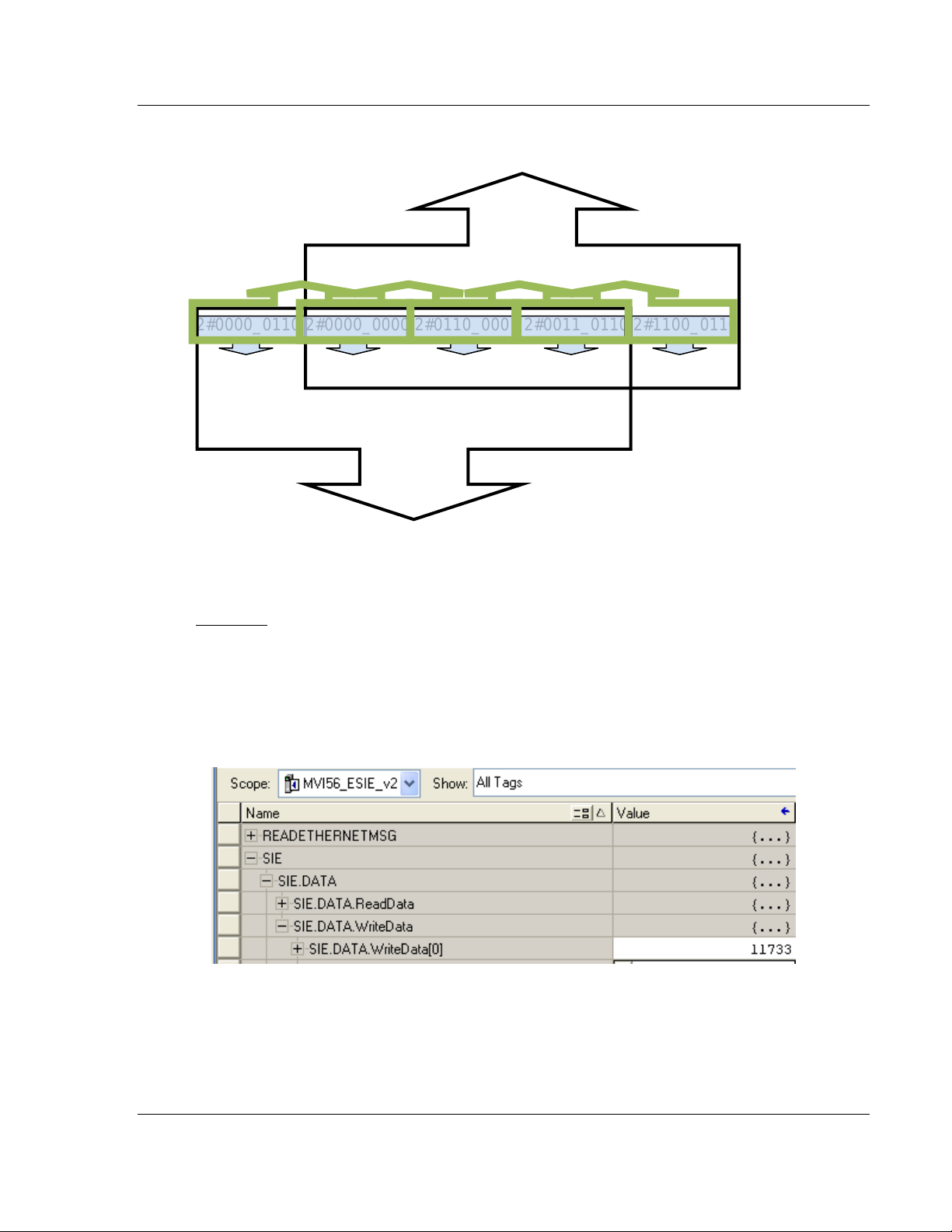
Below is a graphical representation of the addressing of the processor’s memory
locations.
DB1.DBD1
DB1.DBW0 DB1.DBW1 DB1.DBW2 DB1.DBW3
2#0000_0110 2#0000_0000 2#0110_0001 2#0011_0110 2#1100_0110
DB1.DBB0 DB1.DBB1 DB1.DBB2 DB1.DBB3 DB1.DBB4
DB1.DBD0
Example:
Sending an integer value of 11733 from a ControlLogix processor to a Siemens
S7-300 processor demonstrates the addressing scheme in the Siemens S7-300
processor:
In RSLogix 5000:
ProSoft Technology, Inc. Page 67 of 168
September 6, 2012
Page 68

Configuring the MVI56E-SIE Module MVI56E-SIE ♦ ControlLogix Platform
User Manual Client Communication Module
PCB screen shot showing MVI56E-SIE command to send INT data to DB1
address 0:
Row 1 in the SIMATICS Manager screen shot below shows the data transferred
from the SIE.DATA.WriteData[0] controller tag in RSLogix 5000.
If the data is broken up and displayed in binary format, it can be seen that the
binary data stored in the first byte of DB1.DBW 0 is identical to that stored in byte
address DB1.DBB 0. This is because the memory locations referenced by the
first byte of DB1.DBW 0 and by DB1.DBB0 are one and the same, as explained
previously.
Same memory space
Same memory space
DB1.DBW0 DB1.DBW1
2#0010_1101 2#1101_0101 2#1101_0101 2#0101_0111
DB1.DBB0 DB1.DBB1 DB1.DBB1 DB1.DBB2
Page 68 of 168 ProSoft Technology, Inc.
September 6, 2012
Page 69

MVI56E-SIE ♦ ControlLogix Platform Configuring the MVI56E-SIE Module
Client Communication Module User Manual
The first byte of DB1.DBW0 is the same as DB1.DBB0.
The second byte of DB1.DBW0 is the same as DB1.DBB1, and is the same as
the first byte of DB1.DBW1.
In reality, the memory space looks like below:
DB1.DBW0 DB1.DBW1
2#0010_1101 2#1101_0101 2#0101_0111
DB1.DBB0 DB1.DBB1 DB1.DBB2
Note: To access the first address of Data Block, Flag, Input, Output, Timer, and Counter memory
locations in the S7-300 and S7-1200 processors, use the following address syntax.
Data Block -> DB1.DBB0, DB1.DBW0, DB1.DBD0
Flag -> MB0, MW0, MD0
Input -> IB0, IW0, ID0
Output -> QB0, QW0, QD0
Timers -> T0 – T65535
Counters -> C0 – C65535
Note: To access the first address of Data Block, Flag, Input and Output memory locations in the
S7-200 processor, use the following address syntax.
Data Block -> VB0, VW0, VD0
Flag -> MB0, MW0, MD0
Input -> IB0, IW0, ID0
Output -> QB0, QW0, QD0
ProSoft Technology, Inc. Page 69 of 168
September 6, 2012
Page 70

Configuring the MVI56E-SIE Module MVI56E-SIE ♦ ControlLogix Platform
User Manual Client Communication Module
2.2.6 Configuration Examples
Important: The following sections are for example purposes only, and are intended to assist a user
in setting up and configuring module communications with a processor using Siemens Industrial
Ethernet protocol. Before issuing control operations (write commands), please make sure that the
processor is in a safe state to receive these commands. PLEASE ENSURE THAT
COMMUNICATION AND CONTROL OPERATIONS CAN BE CARRIED OUT WITHOUT
DAMAGE TO PLANT AND EQUIPMENT, OR INJURY TO PERSONNEL.
Example 1
This example demonstrates configuration for data transfer from a ControlLogix
processor to an S7-300 processor. The data is transferred from RSLogix
controller tags SIE.WriteData[0] through SIE.WriteData[4] to Data Block 1
addresses 0 through 8 in the Siemens processor, using the INT data type.
1 Copy or move the appropriate data into controller tags SIE.WriteData[0]
through SIE.WriteData[4] in RSLogix 5000.
2 In ProSoft Configuration Builder, expand the module tree. Double-click SIE
CLIENT 0 COMMANDS.
Page 70 of 168 ProSoft Technology, Inc.
September 6, 2012
Page 71

MVI56E-SIE ♦ ControlLogix Platform Configuring the MVI56E-SIE Module
Client Communication Module User Manual
3 In the Edit –SIE Client 0 Commands dialog box, click the ADD ROW button.
4 Click the EDIT ROW button to open the Edit – Row 1 dialog box.
ProSoft Technology, Inc. Page 71 of 168
September 6, 2012
Page 72

Configuring the MVI56E-SIE Module MVI56E-SIE ♦ ControlLogix Platform
Parameter
Value
Comment
Enable
Enabled
Enables the command to be executed.
Internal
Address
1000
In this example, the data will be sourced from register 1000 in
the module’s internal database, which is by default the first
register in the module’s Write Data area. See note below.
Poll Interval
0
A poll interval of 0 enables the fastest polling possible.
Reg Count
5
In this example, five consecutive registers will be written, starting
at Data Block 1, Address 0 (DB1.DBW0).
Swap Code
No Change
The INT data type will be used, so there is no need to consider
word or byte order.
IP Address
10.1.3.179
In this example, the S7-300 Siemens processor addressed in
this command is at 10.1.3.179.
PLC Type
S7-300/
S7-400/
S7-1200
This is the correct value for the S7-300 processor.
Rack
0
In this example, the rack number is 0.
Slot 2 In this example, slot 2 is being used.
TSAP
1000
This parameter is ignored in a command to an S7-300
processor, so it is left at its default value here.
Func Type
Write
In this example, data is being moved into the Siemens
processor.
Data Type
INT
In this example, the INT data type is used.
Address Type
DB
In this example, the DB address type is used.
DB Number
1
In this example, DB Number 1 is used.
Address
0
In this example, the data’s destination address is 0.
User Manual Client Communication Module
5 Select each parameter and edit its value according to the table below. (Use
the IP address applicable to your network.)
Note: In this example, the Internal Address parameter configures this command to source the
Write data from the first register in the module’s Write Data area. The start address of the module’s
Write Data area is determined by the Write Register Start parameter in the module configuration.
By default, the Write Register Start parameter is set to 1000.
Page 72 of 168 ProSoft Technology, Inc.
September 6, 2012
Page 73

MVI56E-SIE ♦ ControlLogix Platform Configuring the MVI56E-SIE Module
Client Communication Module User Manual
6 Click the OK button to save the command configuration and exit the Edit –
Row 1 dialog box. Click the OK button to exit the the Edit –SIE Client 0
Commands dialog box.
7 Right-click the MVI56E-SIE module icon and choose DOWNLOAD FROM PC
TO DEVICE from the dropdown menu.
8 Click the DOWNLOAD button in the Download dialog box.
ProSoft Technology, Inc. Page 73 of 168
September 6, 2012
Page 74

Configuring the MVI56E-SIE Module MVI56E-SIE ♦ ControlLogix Platform
User Manual Client Communication Module
9 After the download is complete, click the OK button.
10 In the RSLogix 5000 program, expand the SIE.CONTROL structure. Enable
the first Client 0 command by entering 1 in
SIE.CONTROL.CmdControl.WriteCmdBits[0].0.
Page 74 of 168 ProSoft Technology, Inc.
September 6, 2012
Page 75

MVI56E-SIE ♦ ControlLogix Platform Configuring the MVI56E-SIE Module
Client Communication Module User Manual
11 Check the variable table in SIMATIC Manager to see if the data transferred
from the ControlLogix processor through the MVI56E-SIE module is present
in the proper locations. Open SIMATIC Manager where the S7-300 processor
has been set up.
12 Right-click the CPU icon, then choose PLC -> MONITOR/MODIFY VARIABLES .
ProSoft Technology, Inc. Page 75 of 168
September 6, 2012
Page 76

Configuring the MVI56E-SIE Module MVI56E-SIE ♦ ControlLogix Platform
User Manual Client Communication Module
13 In the Variable table dialog box, type in the destination addresses as shown
below. Right-click an entry in the Status value column and select MONITOR to
see the variables in addresses DB1.DBW 0 through DB1.DBW 8.
If the values from controller tags SIE.WriteData[0] through SIE.WriteData[4] were
successfully transmitted, they will appear in the Status value column for
addresses DB1.DBW[0] through DB1.DBW[8].
Page 76 of 168 ProSoft Technology, Inc.
September 6, 2012
Page 77

MVI56E-SIE ♦ ControlLogix Platform Configuring the MVI56E-SIE Module
Client Communication Module User Manual
Example 2
This example demonstrates data transfer from an S7-300 processor to a
ControlLogix processor. The data is transferred from addresses 0 through 16
(MD 0 through MD 16) to RSLogix controller tags SIE.ReadData[0] through
SIE.ReadData[9], using the REAL data type and Address Type Flag.
1 In Simatic Manager, type in Flag addresses MD 0 through MD 16. Change
the display format by right-clicking an entry in the Display format column and
selecting FLOATING-POINT from the dropdown list.
2 Type in the Modify values as shown below.
ProSoft Technology, Inc. Page 77 of 168
September 6, 2012
Page 78

Configuring the MVI56E-SIE Module MVI56E-SIE ♦ ControlLogix Platform
User Manual Client Communication Module
3 Right-click an entry in the Modify value column and select UPDATE MONITOR
VALUES from the dropdown list.
The screen should update as shown below.
Page 78 of 168 ProSoft Technology, Inc.
September 6, 2012
Page 79

MVI56E-SIE ♦ ControlLogix Platform Configuring the MVI56E-SIE Module
Client Communication Module User Manual
4 In Prosoft Configuration Builder, expand the module tree and double-click SIE
CLIENT 0 COMMANDS.
5 In the Edit –SIE Client 0 Commands dialog box, click the ADD ROW button.
6 Click the EDIT ROW button to open the Edit – Row 1 dialog box.
ProSoft Technology, Inc. Page 79 of 168
September 6, 2012
Page 80

Configuring the MVI56E-SIE Module MVI56E-SIE ♦ ControlLogix Platform
User Manual Client Communication Module
7 Select each parameter and edit its value as shown below, except for the IP
address. Use the IP address of the S7-300 processor that the command is
addressing. Click the OK button when all the configuration parameters have
been entered.
Note: In this example, the Internal Address parameter configures this command to place the data
received from S7-300 processor into the first register of the module’s Read Data area. The start
address of the module’s Read Data area is determined by the Read Register Start parameter in the
module configuration. By default, the Read Register Start parameter is set to 0.
Page 80 of 168 ProSoft Technology, Inc.
September 6, 2012
Page 81

MVI56E-SIE ♦ ControlLogix Platform Configuring the MVI56E-SIE Module
Client Communication Module User Manual
8 Right-click the MVI56E-SIE module icon and select DOWNLOAD FROM PC TO
DEVICE from the dropdown list.
9 Click the DOWNLOAD button in the Download dialog box.
ProSoft Technology, Inc. Page 81 of 168
September 6, 2012
Page 82

Configuring the MVI56E-SIE Module MVI56E-SIE ♦ ControlLogix Platform
User Manual Client Communication Module
10 When the download is complete, click the OK button.
11 In the RSLogix 5000 program, expand the SIE.CONTROL structure.
Assuming this is the second command in the Command List, enable the
second Client 0 command by entering 1 in
SIE.CONTROL.CmdControl.WriteCmdBits[0].1.
Page 82 of 168 ProSoft Technology, Inc.
September 6, 2012
Page 83

MVI56E-SIE ♦ ControlLogix Platform Configuring the MVI56E-SIE Module
Client Communication Module User Manual
12 Make sure that RSLogix is online with the ControlLogix processor. Check to
see if the data read from the S7-300 processor appears in controller tags
SIE.DATA.ReadData[0] through SIE.DATA.ReadData[9].
Note: Since SIE.DATA.ReadData is an array of integers, the data will not appear in floating-point
format. We will format the data in the following steps.
13 To display the data in floating-point format, copy it into an array with a REAL
data type. Click the EDIT TAGS tab at the bottom of the Controller Tags
window and enter a name for the array (in this example, REALDATA). In the
Data Type column, enter REAL[5].
ProSoft Technology, Inc. Page 83 of 168
September 6, 2012
Page 84

Configuring the MVI56E-SIE Module MVI56E-SIE ♦ ControlLogix Platform
User Manual Client Communication Module
14 Add a copy instruction to the MainRoutine ladder to copy the 10 words from
SIE.DATA.ReadData into the REALDATA array created in the previous step.
Note: The length in the COP instruction is the length of the destination. Since 10 INTs (words)
become 5 REALS (floating-point numbers), the copy length is 5.
15 Verify that the data transferred from S7-300 processor appears correctly in
the REALDATA[0] through REALDATA[4] controller tags.
Page 84 of 168 ProSoft Technology, Inc.
September 6, 2012
Page 85

MVI56E-SIE ♦ ControlLogix Platform Configuring the MVI56E-SIE Module
Client Communication Module User Manual
2.2.7 Static ARP Table
The Static ARP Table defines a list of static IP addresses that the module will
use when an ARP (Address Resolution Protocol) is required. The module will
accept up to 40 static IP/MAC address data sets.
Use the Static ARP table to reduce the amount of network traffic by specifying IP
addresses and their associated MAC (hardware) addresses that the MVI56E-SIE
module will be communicating with regularly.
Important: If the device in the field is changed, this table must be updated to
contain the new MAC address for the device and downloaded to the module. If
the MAC is not changed, no communications with the module will be provided.
IP Address
Dotted notation
This table contains a list of static IP addresses that the module will use when an
ARP is required. The module will accept up to 40 static IP/MAC address data
sets.
Important: If the device in the field is changed, this table must be updated to
contain the new MAC address for the device and downloaded to the module. If
the MAC is not changed, no communications with the module will occur.
Hardware MAC Address
Hex value
This table contains a list of static MAC addresses that the module will use when
an ARP is required. The module will accept up to 40 static IP/MAC address data
sets.
Important: If the device in the field is changed, this table must be updated to
contain the new MAC address for the device and downloaded to the module. If
the MAC is not changed, no communications with the module will occur.
ProSoft Technology, Inc. Page 85 of 168
September 6, 2012
Page 86

Configuring the MVI56E-SIE Module MVI56E-SIE ♦ ControlLogix Platform
User Manual Client Communication Module
2.2.8 Ethernet Configuration
Use this procedure to configure the Ethernet settings for the module. An IP
address, subnet mask and gateway address must be assigned. After this step is
completed, the module can be connected with an Ethernet cable.
1 Determine the network settings for the module, with the help of the network
administrator if necessary. The following information will be needed:
o IP address (fixed IP required) _____ . _____ . _____ . _____
o Subnet mask _____ . _____ . _____ . _____
o Gateway address _____ . _____ . _____ . _____
Note: The gateway address is optional, and is not required for networks that do
not use a default gateway.
2 Double-click the ETHERNET CONFIGURATION icon. This action opens the Edit
dialog box.
3 Edit the values for my_ip, netmask (subnet mask) and gateway (default
gateway).
4 When finished editing, click OK to save the changes and return to the ProSoft
Configuration Builder window.
Page 86 of 168 ProSoft Technology, Inc.
September 6, 2012
Page 87

MVI56E-SIE ♦ ControlLogix Platform Configuring the MVI56E-SIE Module
Client Communication Module User Manual
2.3 Connecting Your PC to the Module
With the module securely mounted, connect one end of the Ethernet cable to the
Config (E1) Port, and the other end to an Ethernet hub or switch accessible from
the same network as the PC. A connection can lso be established directly from
the Ethernet Port on the PC to the Config (E1) Port on the module by using an
Ethernet crossover cable (not included).
2.3.1 Setting Up a Temporary IP Address
Important: ProSoft Configuration Builder locates MVI56E-SIE modules through
UDP broadcast messages. These messages may be blocked by routers or layer
3 switches. In that case, ProSoft Discovery Service will be unable to locate the
modules.
To use ProSoft Configuration Builder, arrange the Ethernet connection so that
there is no router/ layer 3 switch between the computer and the module OR
reconfigure the router/ layer 3 switch to allow routing of the UDP broadcast
messages.
1 In the tree view in ProSoft Configuration Builder, select the MVI56E-SIE
module.
ProSoft Technology, Inc. Page 87 of 168
September 6, 2012
Page 88

Configuring the MVI56E-SIE Module MVI56E-SIE ♦ ControlLogix Platform
User Manual Client Communication Module
2 Click the right mouse button to open a shortcut menu. On the shortcut menu,
choose DIAGNOSTICS.
3 In the Diagnostics window, click the SET UP CONNECTION button.
Page 88 of 168 ProSoft Technology, Inc.
September 6, 2012
Page 89

MVI56E-SIE ♦ ControlLogix Platform Configuring the MVI56E-SIE Module
Client Communication Module User Manual
4 In the Connection Setup dialog box, click the BROWSE DEVICE(S) button to
open the ProSoft Discovery Service. Select the module, then right-click and
choose ASSIGN TEMPORARY IP.
5 The module’s default IP address is 192.168.0.250. Choose an unused IP
within the same subnet, and then click OK.
Important: The temporary IP address is only valid until the next time the module
is initialized. For information on how to set the module’s permanent IP address,
see Ethernet Configuration (page 86).
ProSoft Technology, Inc. Page 89 of 168
September 6, 2012
Page 90

Configuring the MVI56E-SIE Module MVI56E-SIE ♦ ControlLogix Platform
User Manual Client Communication Module
6 Close the ProSoft Discovery Service window. Enter the temporary IP in the
Ethernet address field of the Connection Setup dialog box, then click the
TEST CONNECTION button to verify that the module is accessible with the
current settings.
7 If the Test Connection is successful, click CONNECT. The Diagnostics menu
will display in the Diagnostics window.
Page 90 of 168 ProSoft Technology, Inc.
September 6, 2012
Page 91

MVI56E-SIE ♦ ControlLogix Platform Configuring the MVI56E-SIE Module
Client Communication Module User Manual
2.4 Downloading the Project to the Module
Note: For alternative methods of connecting to the module with your PC, refer to
Using CIPconnect to Connect to the Module (page 92) or Using RSWho to
Connect to the Module (page 102).
In order for the module to use the settings you configured, you must download
(copy) the updated Project file from your PC to the module.
1 In the tree view in ProSoft Configuration Builder, click once to select the
MVI56E-SIE module.
2 Open the PROJECT menu, and then choose MODULE / DOWNLOAD.
This action opens the Download dialog box. Notice that the Ethernet address
field contains the temporary IP address you assigned previously. ProSoft
Configuration Builder will use this temporary IP address to connect to the
module.
Click TEST CONNECTION to verify that the IP address allows access to the
module.
3 If the connection succeeds, click DOWNLOAD to transfer the Ethernet
configuration to the module.
If the Test Connection procedure fails, an error message will appear. To correct
the error, follow these steps.
1 Click OK to dismiss the error message.
ProSoft Technology, Inc. Page 91 of 168
September 6, 2012
Page 92

Configuring the MVI56E-SIE Module MVI56E-SIE ♦ ControlLogix Platform
User Manual Client Communication Module
2 In the Download dialog box, click BROWSE DEVICE(S) to open ProSoft
Discovery Service.
3 Select the module, and then click the right mouse button to open a shortcut
menu. On the shortcut menu, choose SELECT FOR PCB.
4 Close ProSoft Discovery Service.
5 Click DOWNLOAD to transfer the configuration to the module.
2.4.1 Using CIPconnect to Connect to the Module
CIPconnect® can be used to connect a PC to the MVI56E-SIE module over
Ethernet using Rockwell Automation’s 1756-ENBT EtherNet/IP® module. This
allows for configuringof the MVI56E-SIE module and network, uploading and
downloading of files, and viewing of network and module diagnostics from a PC.
RSLinx is not required when using CIPconnect. All that is needed:
The IP addresses and slot numbers of any 1756-ENBT modules in the path
The ControlNet node numbers and slot numbers of any 1756-CNBx
ControlNet Bridge modules in the path
The slot number of the MVI56E-SIE in the destination ControlLogix chassis
(the last ENBT/CNBx and chassis in the path).
Page 92 of 168 ProSoft Technology, Inc.
September 6, 2012
Page 93

MVI56E-SIE ♦ ControlLogix Platform Configuring the MVI56E-SIE Module
Client Communication Module User Manual
To use CIPconnect, follow these steps.
1 In the Select Connection Type dropdown list, choose 1756-ENBT. The
default path appears in the text box, as shown in the following illustration.
2 Click CIP PATH EDIT to open the CIPconnect Path Editor dialog box.
ProSoft Technology, Inc. Page 93 of 168
September 6, 2012
Page 94

Configuring the MVI56E-SIE Module MVI56E-SIE ♦ ControlLogix Platform
Parameter
Description
Source Module
Source module type. This field is automatically selected
depending on the destination module of the last rack
(1756-CNB or 1756-ENBT).
Source Module IP Address
IP address of the source module (only applicable for
1756-ENBT)
Source Module Node Address
Node address of the source module (only applicable for
1756-CNB)
Destination Module
Select the destination module associated to the source module
in the rack. The connection between the source and destination
modules is performed through the backplane.
Destination Module Slot Number
The slot number where the destination MVI56E module is
located.
User Manual Client Communication Module
The CIPconnect Path Editor allows the path between the PC and the MVI56ESIE module to be defined. The first connection from the PC is always a 1756ENBT (Ethernet/IP) module.
Each row corresponds to a physical rack in the CIP path.
If the MVI56E-SIE module is located in the same rack as the first 1756-ENBT
module, select RACK NO. 1 and configure the associated parameters.
If the MVI56E-SIE is available in a remote rack (accessible through
ControlNet or Ethernet/IP), include all racks (by using the ADD RACK button).
To use the CIPconnect Path Editor, follow these steps.
1 Configure the path between the 1756-ENBT connected to the PC and the
MVI56E-SIE module.
o If the module is located in a remote rack, add more racks to configure the
full path.
o The path can only contain ControlNet or Ethernet/IP networks.
o The maximum number of supported racks is six.
2 Click CONSTRUCT CIP PATH to build the path in text format
3 Click OK to confirm the configured path.
Page 94 of 168 ProSoft Technology, Inc.
September 6, 2012
Page 95
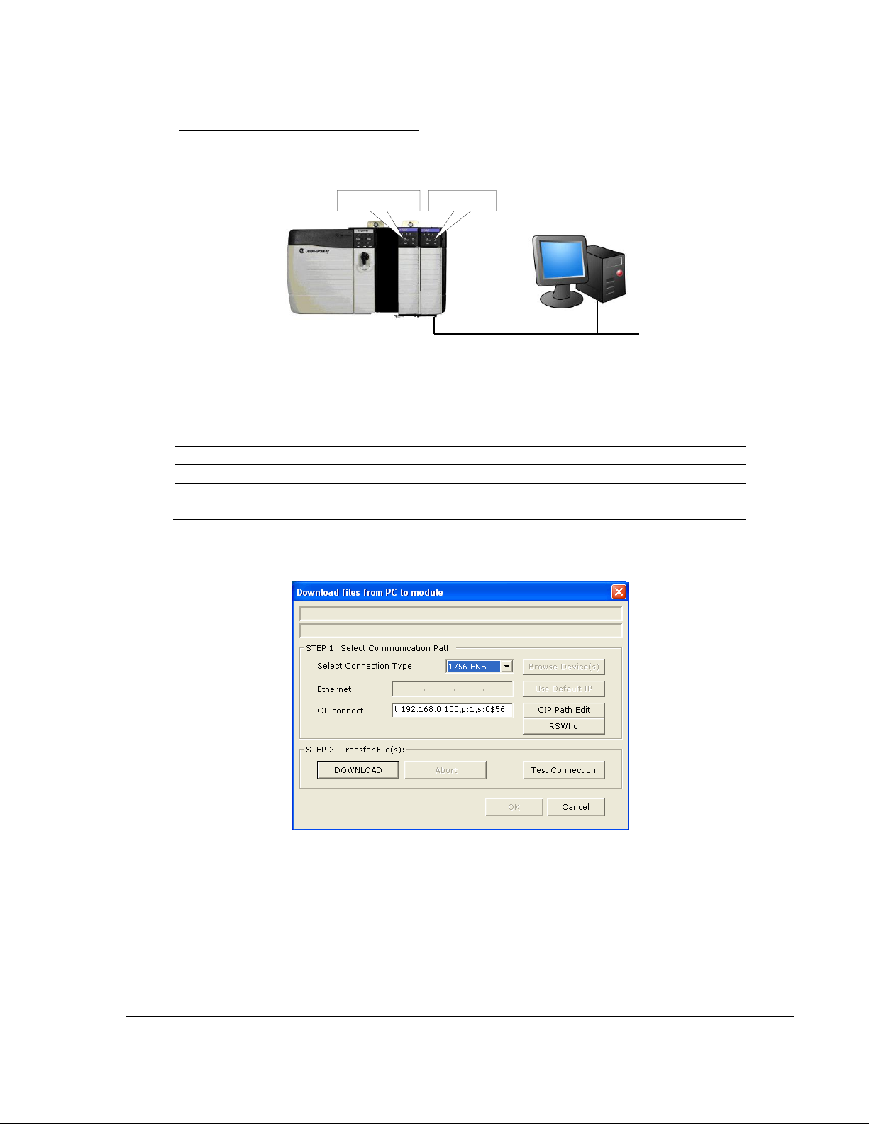
MVI56E-SIE ♦ ControlLogix Platform Configuring the MVI56E-SIE Module
Ethernet
Rack 1
MVI56E Module 1756-ENBT
0 1 2
3
Slot
Module
Network Address
0
ControlLogix Processor
-
1
Any
-
2
MVI56E-SIE
-
3
1756-ENBT
IP=192.168.0.100
Client Communication Module User Manual
Example 1: Local Rack Application
For this example, the MVI56E-SIE module is located in the same rack as the
1756-ENBT that is connected to the PC.
Rack 1
1 In the Download dialog box, click CIP PATH EDIT.
ProSoft Technology, Inc. Page 95 of 168
September 6, 2012
Page 96

Configuring the MVI56E-SIE Module MVI56E-SIE ♦ ControlLogix Platform
User Manual Client Communication Module
2 Configure the path as shown in the following illustration, and click
CONSTRUCT CIP PATH to build the path in text format.
Click OK to close the CIPconnect Path Editor and return to the Download
dialog box.
3 Check the new path in the Download dialog box.
Page 96 of 168 ProSoft Technology, Inc.
September 6, 2012
Page 97

MVI56E-SIE ♦ ControlLogix Platform Configuring the MVI56E-SIE Module
Client Communication Module User Manual
4 Click TEST CONNECTION to verify that the physical path is available. The
following message should be displayed upon success.
5 Click OK to close the Test Connection pop-up and then click DOWNLOAD to
download the configuration files to the module through the path.
ProSoft Technology, Inc. Page 97 of 168
September 6, 2012
Page 98

Configuring the MVI56E-SIE Module MVI56E-SIE ♦ ControlLogix Platform
Ethernet
Rack 1
0 1 2 3
ControlNet
0
1 2 3 4 5
6
Rack 2
1756-ENBT
1756-CNB
1756-CNB
MVI56E Module
Slot
Module
Network Address
0
ControlLogix Processor
-
1
1756-CNB
Node = 1
2
1756-ENBT
IP=192.168.0.100
3
Any
-
Slot
Module
Network Address
0
Any
-
1
Any
-
2
Any
-
3
Any
-
4
Any
-
5
1756-CNB
Node = 2
6
MVI56E-SIE
-
User Manual Client Communication Module
Example 2: Remote Rack Application
For this example, the MVI56E-SIE module is located in a remote rack accessible
through ControlNet, as shown in the following illustration.
Rack 1
Rack 2
Page 98 of 168 ProSoft Technology, Inc.
September 6, 2012
Page 99

MVI56E-SIE ♦ ControlLogix Platform Configuring the MVI56E-SIE Module
Client Communication Module User Manual
1 In the Download dialog box, click CIP PATH EDIT.
2 Configure the path as shown in the following illustration and click CONSTRUCT
CIP PATH to build the path in text format.
Click OK to close the CIPconnect Path Editor and return to the Download
dialog box.
ProSoft Technology, Inc. Page 99 of 168
September 6, 2012
Page 100
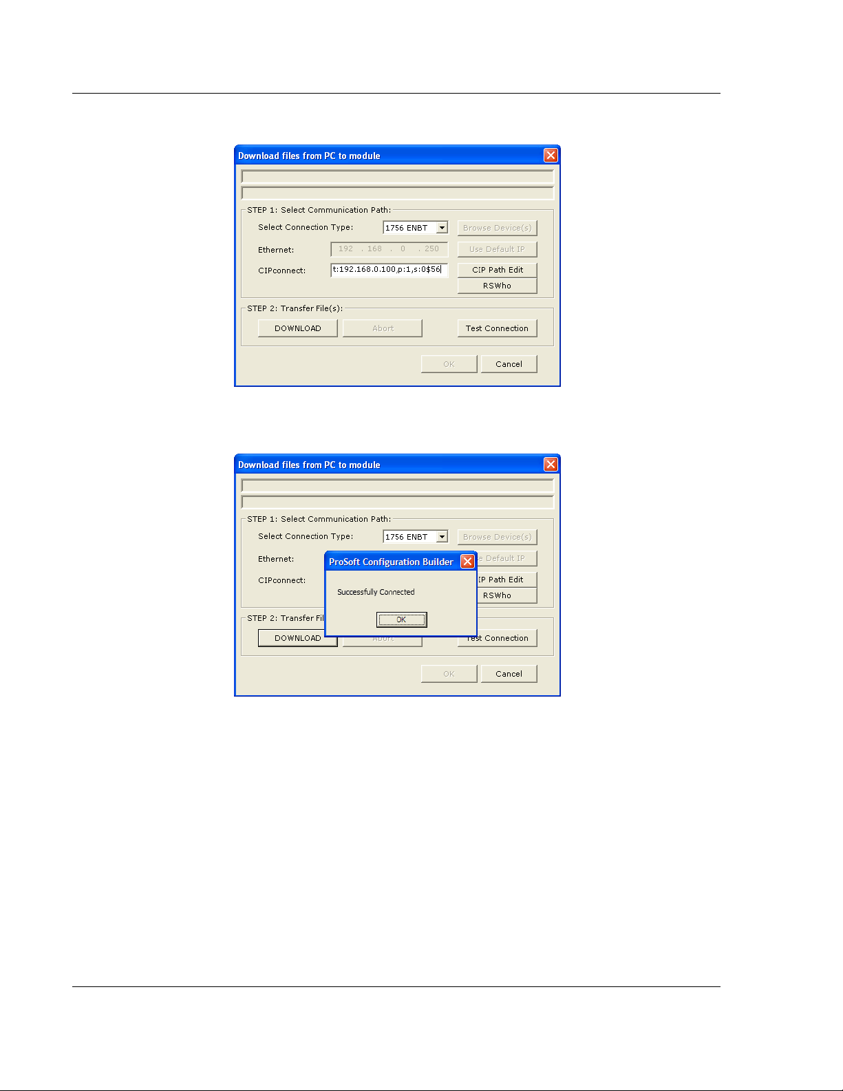
Configuring the MVI56E-SIE Module MVI56E-SIE ♦ ControlLogix Platform
User Manual Client Communication Module
3 Check the new path in the Download dialog box.
4 Click TEST CONNECTION to verify that the physical path is available. The
following message should be displayed upon success.
Page 100 of 168 ProSoft Technology, Inc.
September 6, 2012
 Loading...