

Page 1
MVI56E-MNETR
ControlLogix Platform
Modbus TCP/IP Interface Module with
Reduced Data Block
August 31, 2009
USER MANUAL
Page 2

Important Safety Information - MVI56E Modules
North America Warnings
A Warning - Explosion Hazard - Substitution of components may impair suitability for Class I, Division 2.
B Warning - Explosion Hazard - When in Hazardous Locations, turn off power before replacing or rewiring
modules.
Warning - Explosion Hazard - Do not disconnect equipment unless power has been switched off or the area is
known to be nonhazardous.
C Suitable for use in Class I, Division 2 Groups A, B, C, and D, T5 Hazardous Locations or Non-Hazardous
Locations.
ATEX Warnings and Conditions of Safe Usage
Power, Input, and Output (I/O) wiring must be in accordance with the authority having jurisdiction
A Warning - Explosion Hazard - When in hazardous locations, turn off power before replacing or wiring modules.
B Warning - Explosion Hazard - Do not disconnect equipment unless power has been switched off or the area is
known to be non-hazardous.
C These products are intended to be mounted in an IP54 enclosure. The devices shall provide external means to
prevent the rated voltage being exceeded by transient disturbances of more than 40%. This device must be used
only with ATEX certified backplanes.
D DO NOT OPEN WHEN ENERGIZED.
Electrical Ratings
Backplane Current Load: 800 mA @ 5 V DC; 3mA @ 24V DC
Operating Temperature: 0 to 60°C (32 to 140°F)
Storage Temperature: -40 to 85°C (-40 to 185°F)
Shock: 30g Operational; 50g non-operational; Vibration: 5 g from 10 to 150 Hz
Relative Humidity 5% to 95% (non-condensing)
All phase conductor sizes must be at least 1.3 mm (squared) and all earth ground conductors must be at least
4mm (squared).
Markings
ANSI / ISA ISA 12.12.01 Class I Division 2, GPs A, B, C, D
CSA/cUL C22.2 No. 213-M1987
CSA CB Certified IEC61010
ATEX EN60079-0 Category 3, Zone 2
EN60079-15
243333 E183151
CL I Div 2 GP A, B, C, D
Temp Code T5
II 3 G
Ex nA nL IIC T5 X
0° C <= Ta <= 60° C
II – Equipment intended for above ground use (not for use in mines).
3 – Category 3 equipment, investigated for normal operation only.
G – Equipment protected against explosive gasses.
Page 3

Battery Life Advisory
The module uses a rechargeable Lithium Vanadium Pentoxide battery to backup the real-time clock and CMOS
settings. The battery itself should last for the life of the module. However, if left in an unpowered state for 14 to 21
days, the battery may become fully discharged and require recharging by being placed in a powered-up ControlLogix
chassis. The time required to fully recharge the battery may be as long as 24hours.
Once it is fully charged, the battery provides backup power for the CMOS setup and the real-time clock for
approximately 21 days. Before you remove a module from its power source, ensure that the battery within the module
is fully charged (the BATT LED on the front of the module goes OFF when the battery is fully charged. If the battery is
allowed to become fully discharged, the module will revert to the default BIOS and clock s ettings.
Note: The battery is not user-replaceable or serviceable.
Your Feedback Please
We always want you to feel that you made the right decision to use our products. If you have suggestions, comments,
compliments or complaints about the product, documentation, or support, please write or call us.
ProSoft Technology
5201 Truxtun Ave., 3rd Floor
Bakersfield, CA 93309
+1 (661) 716-5100
+1 (661) 716-5101 (Fax)
www.prosoft-technology.com
support@prosoft-technology.com
Copyright © ProSoft Technology, Inc. 2009. All Rights Reserved.
MVI56E-MNETR User Manual
August 31, 2009
ProSoft Technology
Technology, Inc. All other brand or product names are or may be trademarks of, and are used to identify products
and services of, their respective owners.
®
, ProLinx ®, inRAx ®, ProTalk®, and RadioLinx ® are Registered Trademarks of ProSoft
ProSoft Technology® Product Documentation
In an effort to conserve paper, ProSoft Technology no longer includes printed manuals with our product shipments.
User Manuals, Datasheets, Sample Ladder Files, and Configuration Files are provide d on the enclosed CD-ROM,
and are available at no charge from our web site: www.prosoft-technology.com
Printed documentation is available for purchase. Contact ProSoft Technology for pricing and availability.
North America: +1.661.716.5100
Asia Pacific: +603.7724.2080
Europe, Middle East, Africa: +33 (0) 5.3436.87.20
Latin America: +1.281.298.9109
Page 4

Page 5

Contents MVI56E-MNETR ♦ ControlLogix Platform
User Manual Modbus TCP/IP Interface Module with Reduced Data Block
Contents
Important Safety Information - MVI56E Modules................................................................................2
Battery Life Advisory...........................................................................................................................3
Your Feedback Please........................................................................................................................3
ProSoft Technology® Product Documentation....................................................................................3
Guide to the MVI56E-MNETR User Manual 7
1 Start Here 9
1.1 What’s Different?.....................................................................................................10
1.2 System Requirements.............................................................................................10
1.3 Package Contents...................................................................................................11
1.4 Setting Jumpers ......................................................................................................12
1.5 Install the Module in the Rack.................................................................................12
1.6 Install the Configuration Tools.................................................................................14
1.7 Connect your PC to the Module..............................................................................15
1.8 Set Temporary IP Address......................................................................................15
1.9 Connect to the Module's Web Page........................................................................23
1.10 Upload the Add-On Instruction from the Module.....................................................25
1.11 Create a new RSLogix 5000 project .......................................................................26
2 Configuring the MVI56E-MNETR Module 49
2.1 Using ProSoft Configuration Builder Software........................................................49
2.2 Download the Project to the Module.......................................................................67
2.3 Using CIPconnect® to Connect to the Module ........................................................68
3 Ladder Logic 79
3.1 MNETRModuleDef..................................................................................................79
3.2 Modbus Message Data ...........................................................................................84
4 Diagnostics and Troubleshooting 85
4.1 Reading Status Data from the Module....................................................................85
4.2 The Diagnostics Menu.............................................................................................86
4.3 Monitoring Module Information................................................................................89
4.4 Monitoring Backplane Information...........................................................................90
4.5 Monitoring Database Information............................................................................91
4.6 Monitoring MNET Client Information.......................................................................92
4.7 Monitoring MNET Server Information......................................................................93
4.8 Data Analyzer..........................................................................................................93
4.9 LED Status Indicators..............................................................................................97
5 Reference 101
5.1 Product Specifications...........................................................................................101
ProSoft Technology, Inc. Page 5 of 153
August 31, 2009
Page 6

MVI56E-MNETR ♦ ControlLogix Platform Contents
Modbus TCP/IP Interface Module with Reduced Data Block User Manual
5.2 Functional Overview............................................................................................. 103
5.3 Ethernet Cable Specifications............................................................................... 118
5.4 MVI56E-MNETR Status Data Definition............................................................... 119
5.5 Modbus Protocol Specification ............................................................................. 121
5.6 Using the Rung Import with Utility Add-On Instruction......................................... 132
5.7 Adding the Module to an Existing Project............................................................. 141
5.8 Using the Sample Program - RSLogix Version 15 and earlier............................. 144
6 Support, Service & Warranty 145
6.1 How to Contact Us: Technical Support................................................................. 145
6.2 Return Material Authorization (RMA) Policies and Conditions............................. 146
6.3 LIMITED WARRANTY.......................................................................................... 147
Index 151
Page 6 of 153 ProSoft Technology, Inc.
August 31, 2009
Page 7

Start Here MVI56E-MNETR ♦ ControlLogix Platform
User Manual Modbus TCP/IP Interface Module with Reduced Data Block
Guide to the MVI56E-MNETR User Manual
Function Section to Read Details
Introduction
(Must Do)
Verify Communication,
Diagnostic and
Troubleshooting
Reference
Product Specifications
Functional Overview
Support, Service, and
Warranty
Index
→
→
→
→
Start Here (page 9)
Verifying
Communication
(page 97)
Diagnostics and
Troubleshooting
(page
85)
Reference (page
101)
Functional Overview
(page
103)
Product
Specifications (page
101)
Support, Service
and Warranty (page
145)
This Section introduces the customer to the
module. Included are: package contents,
system requirements, hardware installation, and
basic configuration.
This section describes how to verify
communications with the network. Diagnostic
and Troubleshooting procedures.
These sections contain general references
associated with this product, Specifications, and
the Functional Overview.
This section contains Support, Service and
Warranty information.
Index of chapters.
ProSoft Technology, Inc. Page 7 of 153
August 31, 2009
Page 8

MVI56E-MNETR ♦ ControlLogix Platform Start Here
Modbus TCP/IP Interface Module with Reduced Data Block User Manual
Page 8 of 153 ProSoft Technology, Inc.
August 31, 2009
Page 9
Start Here MVI56E-MNETR ♦ ControlLogix Platform User Manual Modbus TCP/IP Interface Module with Reduced Data Block
1 Start Here
In This Chapter
What’s Different?...................................................................................10
System Requirements...........................................................................10
Package Contents.................................................................................11
Setting Jumpers ....................................................................................12
Install the Module in the Rack ...............................................................12
Install the Configuration Tools...............................................................14
Connect your PC to the Module ............................................................15
Set Temporary IP Address....................................................................15
Connect to the Module's Web Page......................................................23
Upload the Add-On Instruction from the Module ...................................25
Create a new RSLogix 5000 project......................................................26
To get the most benefit from this User Manual, you should have the following
skills:
Rockwell Automation
®
RSLogix™ software: launch the program, configure
ladder logic, and transfer the ladder logic to the processor
Microsoft Windows: install and launch programs, execute menu commands,
navigate dialog boxes, and enter data.
Hardware installation and wiring: install the module, and safely connect
Modbus TCP/IP and ControlLogix devices to a power source and to the
MVI56E-MNETR module’s application port(s).
Caution: You must be able to complete the application without exposing personnel or
equipment to unsafe or inappropriate working conditions.
ProSoft Technology, Inc. Page 9 of 153
August 31, 2009
Page 10

MVI56E-MNETR ♦ ControlLogix Platform Start Here
Modbus TCP/IP Interface Module with Reduced Data Block User Manual
1.1 What’s Different?
Modbus TCP/IP Interface Module with Reduced Data Block products are
backward compatible with existing MVI56 products in the field, including ladder
logic and module configuration files. Easily swap and upgrade products while
benefiting from an array of new features designed to improve interoperability and
enhance the user experience.
Web Page: The web page allows access to manuals and other tools
previously provided on a product CD.
ProSoft Configuration Builder (PCB): New Windows software for
diagnostics, connecting via the module's Ethernet port or CIPconnect
upload/download module configuration information and access
troubleshooting features and functions.
ProSoft Discovery Service (PDS): Utility software to find and display a list
of all MVI56E modules on the network and to temporarily change the IP
address to connect with the module's web page.
CIPconnect
from the Ethernet network through a ControlLogix 1756-ENBT EtherNet/IP
module.
Personality Card: An industrial compact flash memory card storing the
module’s complete configuration and Ethernet settings, allowing quick and
easy replacement.
LED Scrolling Diagnostic Display: 4-character, alphanumeric display,
providing English messages for status and alarm data, and for processor and
network communication status.
®
-enabled: Allows PC-to-module configuration and diagnostics
®
to
®
1.2 System Requirements
The MVI56E-MNETR module requires the following minimum hardware and
software components:
Rockwell Automation
higher), with compatible power supply, and one free slot in the rack for the
MVI56E-MNETR module. The module requires 800mA of available 5 VDC
power
Rockwell Automation RSLogix 5000 programming software
o Version 16 or higher required for Add-On Instruction
o Version 15 or lower must use Sample Ladder, available from
www.prosoft-technology.com
Rockwell Automation RSLinx communication software version 2.51 or higher
ProSoft Configuration Builder (PCB) (included)
ProSoft Discovery Service (PDS) (included in PCB)
Pentium
®
II 450 MHz minimum. Pentium III 733 MHz (or better)
recommended
Supported operating systems:
o Microsoft Windows Vista
o Microsoft Windows XP Professional with Service Pack 1 or 2
o Microsoft Windows 2000 Professional with Service Pack 1, 2, or 3
o Microsoft Windows Server 2003
Page 10 of 153 ProSoft Technology, Inc.
®
ControlLogix™ processor (firmware version 10 or
August 31, 2009
Page 11

Start Here MVI56E-MNETR ♦ ControlLogix Platform
User Manual Modbus TCP/IP Interface Module with Reduced Data Block
128 Mbytes of RAM minimum, 256 Mbytes of RAM recommended
100 Mbytes of free hard disk space (or more based on application
requirements)
256-color VGA graphics adapter, 800 x 600 minimum resolution (True Color
1024 × 768 recommended)
CD-ROM drive
Note: The Hardware and Operating System requirements in this list are the minimum
recommended to install and run software provided by ProSoft Technology. Other third party
applications may have different minimum requirements. Refer to the documentation for any third
party applications for system requirements.
Note: You can install the module in a local or remote rack. For remote rack installation, the module
requires EtherNet/IP or ControlNet communication with the processor.
1.3 Package Contents
The following components are included with your MVI56E-MNETR module, and
are all required for installation and configuration.
Important: Before beginning the installation, please verify that all of the following items are
present.
Qty. Part Name Part Number Part Description
1
1 Cable RL-CBL025 5 foot Ethernet Straight-Through Cable (Gray)
1
1 Insert MVI56E-MNETR Quick Start Guide
MVI56EMNETR
Module
ProSoft
Solutions CD
<ModelNumbeXTr>
CD-013
Modbus TCP/IP Interface Module with Reduced
Data Block
Contains configuration tools for the MVI56EMNETR module
If any of these components are missing, please contact ProSoft Technology
Support for replacement parts.
ProSoft Technology, Inc. Page 11 of 153
August 31, 2009
Page 12
MVI56E-MNETR ♦ ControlLogix Platform Start Here
Modbus TCP/IP Interface Module with Reduced Data Block User Manual
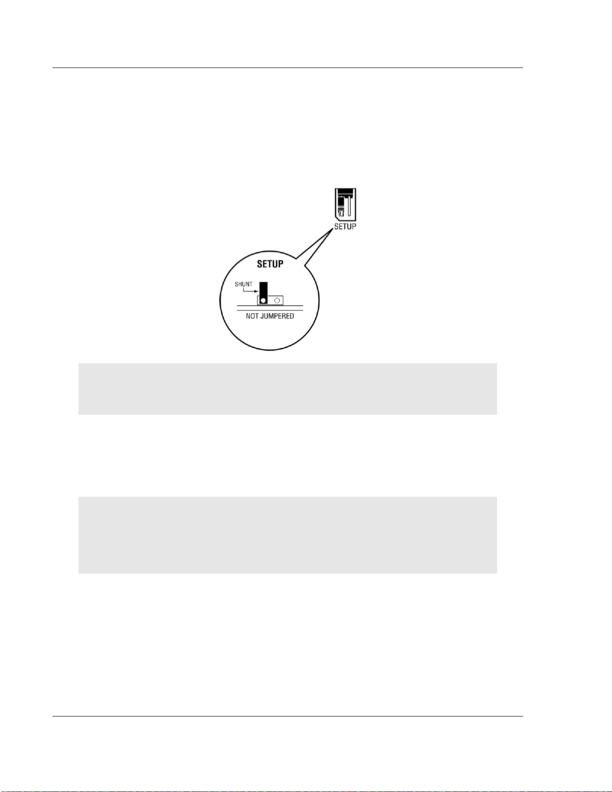
1.4 Setting Jumpers
The Setup Jumper acts as "write protection" for the module’s flash memory. In
"write protected" mode, the Setup pins are not connected, and the module’s
firmware cannot be overwritten. Do not jumper the Setup pins together unless
you are directed to do so by ProSoft Technical Support.
The following illustration shows the MVI56E-MNETR jumper configuration.
Note: If you are installing the module in a remote rack, you may prefer to leave the Setup pins
jumpered. That way, you can update the module’s firmware without requiring physical access to
the module.
1.5 Install the Module in the Rack
If you have not already installed and configured your ControlLogix processor and
power supply, please do so before installing the MVI56E-MNETR module. Refer
to your Rockwell Automation product documentation for installation instructions.
Warning: You must follow all safety instructions when installing this or any other electronic
devices. Failure to follow safety procedures could result in damage to hardware or data, or even
serious injury or death to personnel. Refer to the documentation for each device you plan to
connect to verify that suitable safety procedures are in place before installing or servicing the
device.
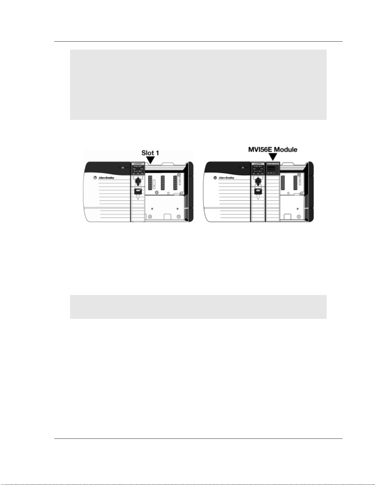
After you have checked the placement of the jumpers, insert the MVI56EMNETR into the ControlLogix chassis. Use the same technique recommended by
Rockwell Automation to remove and install ControlLogix modules.
You can install or remove ControlLogix system components while chassis power
is applied and the system is operating. However, please note the following
warning.
Page 12 of 153 ProSoft Technology, Inc.
August 31, 2009
Page 13
Start Here MVI56E-MNETR ♦ ControlLogix Platform
User Manual Modbus TCP/IP Interface Module with Reduced Data Block
Warning: When you insert or remove the module while backplane power is on, an electrical arc
can occur. An electrical arc can cause personal injury or property damage by:
sending an erroneous signal to your system’s actuators causing unintended machine motion
or loss of process control
causing an explosion in a hazardous environment
Verify that power is removed or the area is non-hazardous before proceeding. Repeated electrical
arcing causes excessive wear to contacts on both the module and its mating connector. Worn
contacts may create electrical resistance that can affect module operation.
1 Align the module with the top and bottom guides, and then slide it into the
rack until the module is firmly against the backplane connector.
2 With a firm, steady push, snap the module into place.
3 Check that the holding clips on the top and bottom of the module are securely
in the locking holes of the rack.
4 Make a note of the slot location. You must identify the slot in which the
module is installed in order for the sample program to work correctly. Slot
numbers are identified on the green circuit board (backplane) of the
ControlLogix rack.
5 Turn power ON.
Note: If you insert the module improperly, the system may stop working, or may behave
unpredictably.
ProSoft Technology, Inc. Page 13 of 153
August 31, 2009
Page 14
MVI56E-MNETR ♦ ControlLogix Platform Start Here
Modbus TCP/IP Interface Module with Reduced Data Block User Manual
1.6 Install the Configuration Tools
1.6.1 Install ProSoft Configuration Builder
To install ProSoft Configuration Builder from the CD-ROM
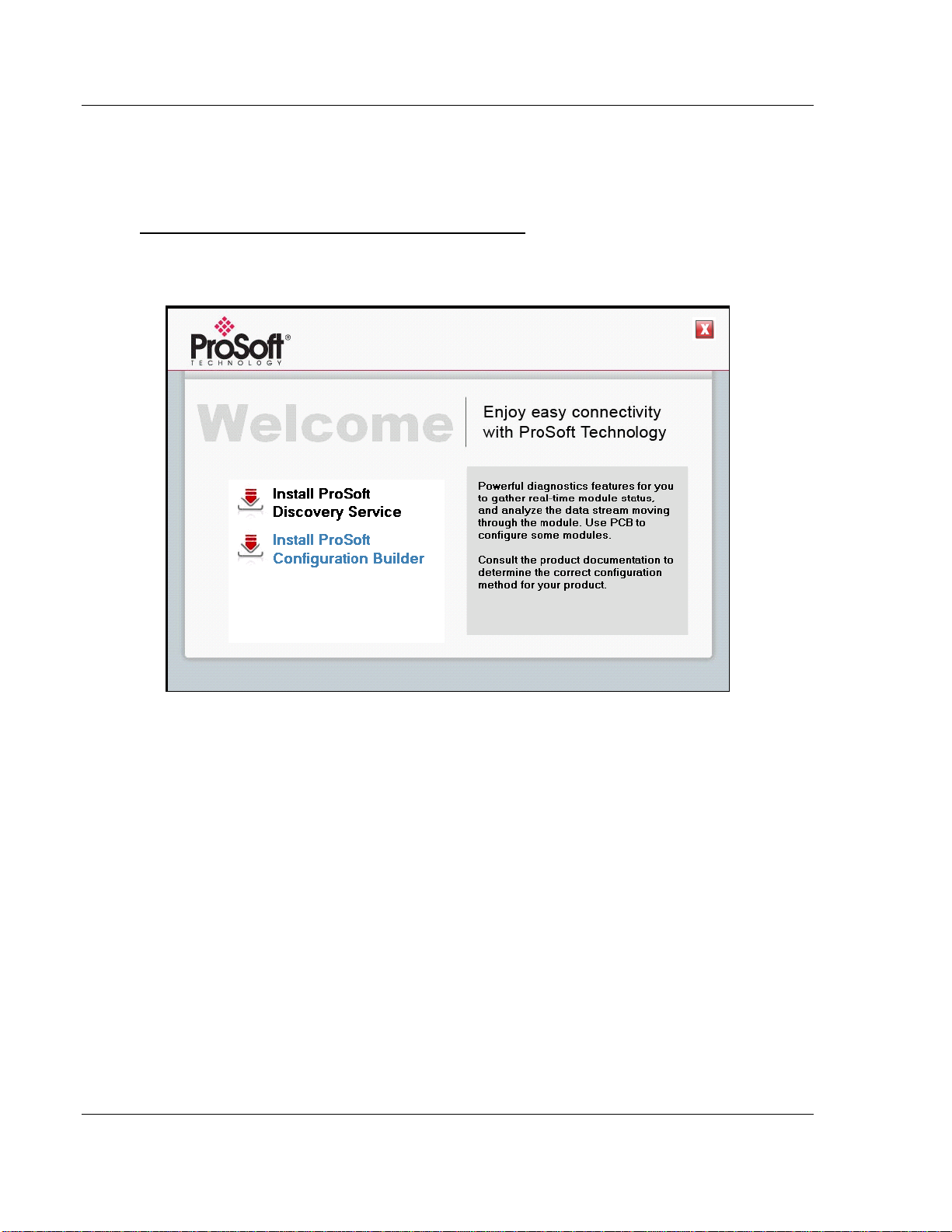
1 Insert the ProSoft Solutions CD-ROM into the CD drive of your PC. Wait for
the startup screen to appear.
2 On the startup screen, click I
NSTALL PROSOFT CONFIGURATION BUILDER. This
action starts the installation wizard for ProSoft Configuration Builder.
3 Click N
EXT on each page of the installation wizard. Click FINISH on the last
page of the wizard.
Page 14 of 153 ProSoft Technology, Inc.
August 31, 2009
Page 15
Start Here MVI56E-MNETR ♦ ControlLogix Platform
User Manual Modbus TCP/IP Interface Module with Reduced Data Block
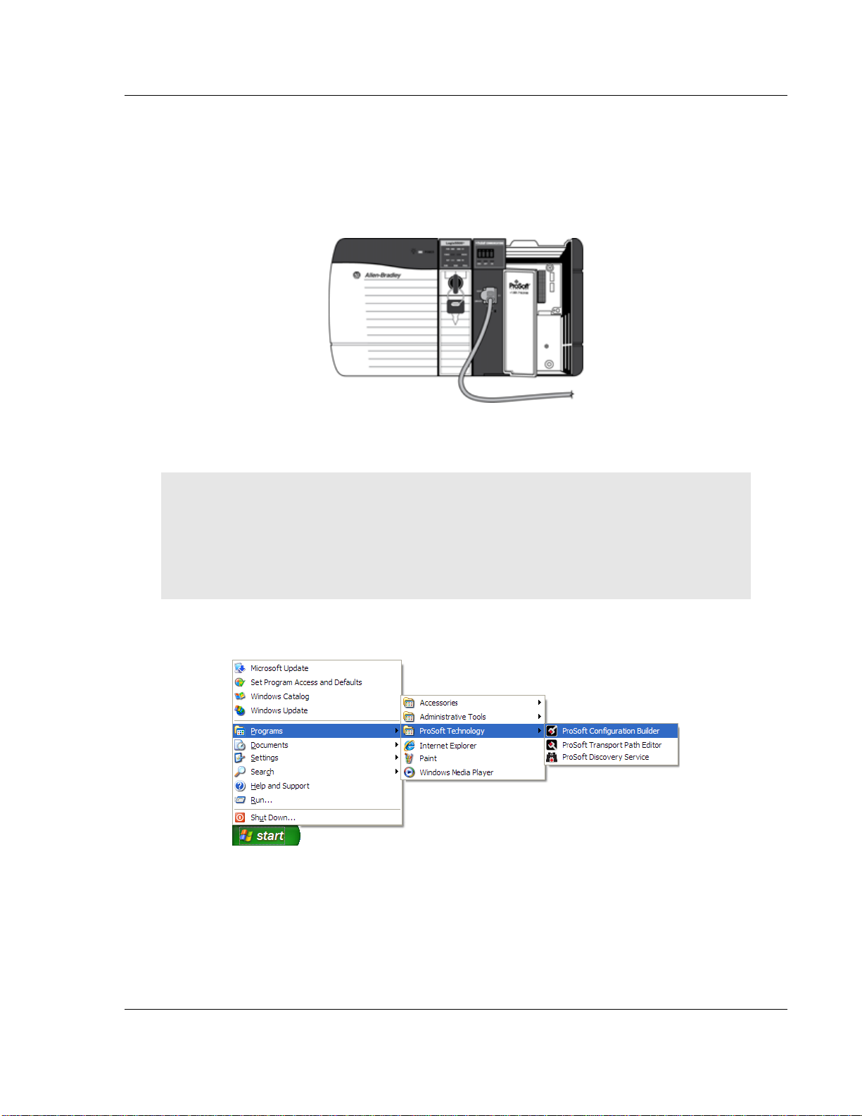
1.7 Connect your PC to the Module
With the module securely mounted, connect one end of the Ethernet cable to the
C
ONFIG (E1) Port, and the other end to an Ethernet hub or switch accessible from
the same network as your PC. Or, you can connect directly from the Ethernet
Port on your PC to the C
ONFIG (E1) Port on the module.
1.8 Set Temporary IP Address
Important: ProSoft Configuration Builder locates MVI56E-MNETR modules through UDP
broadcast messages. These messages may be blocked by routers or layer 3 switches. In that
case, ProSoft Discovery Service will be unable to locate the modules.
To use ProSoft Configuration Builder, arrange the Ethernet connection so that there is no router/
layer 3 switch between the computer and the module OR reconfigure the router/layer 3 switch to
allow the routing of the UDP broadcast messages.
1 Click the START button, and then navigate to PROGRAMS / PROSOFT
TECHNOLOGY
2 Click to start P
ROSOFT CONFIGURATION BUILDER
ProSoft Technology, Inc. Page 15 of 153
August 31, 2009
Page 16
MVI56E-MNETR ♦ ControlLogix Platform Start Here
Modbus TCP/IP Interface Module with Reduced Data Block User Manual
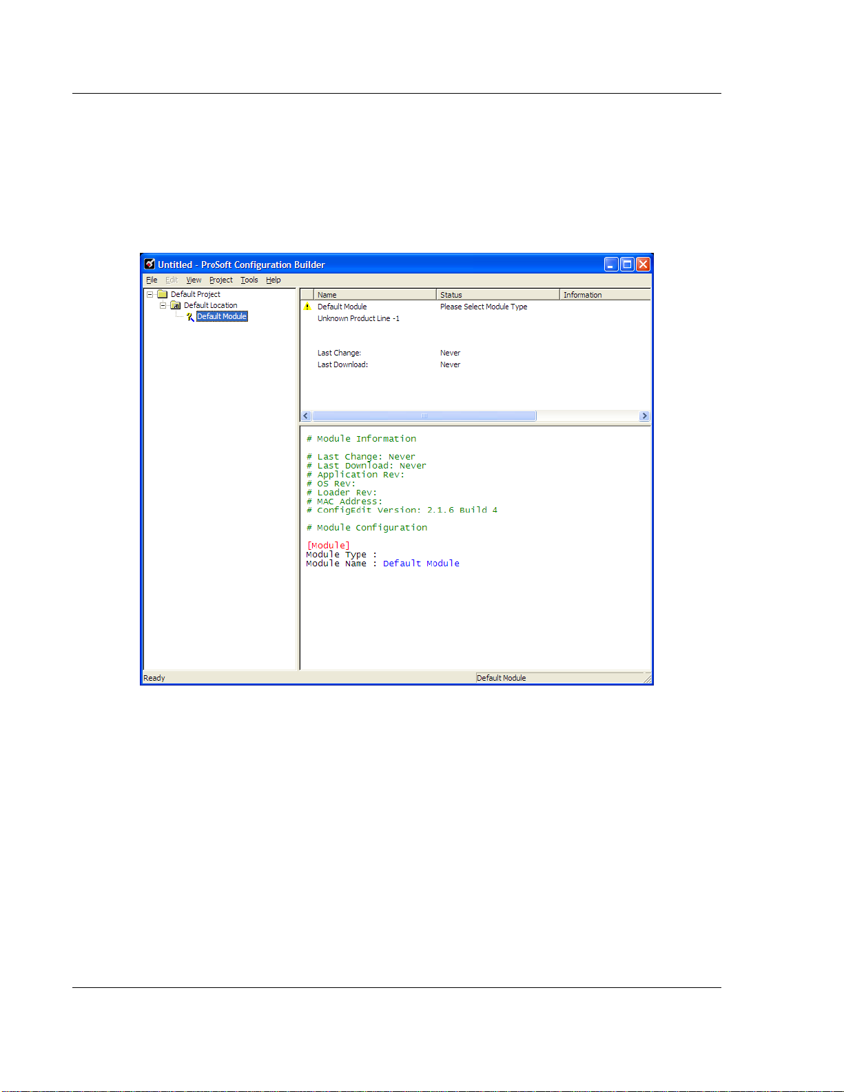
If you have used other Windows configuration tools before, you will find the
screen layout familiar. PCB’s window consists of a tree view on the left, and
an information pane and a configuration pane on the right side of the window.
When you first start PCB, the tree view consists of folders for D
EFAULT
PROJECT and DEFAULT LOCATION, with a DEFAULT MODULE in the Default
Location folder. The following illustration shows the PCB window with a new
project.
3 Use the mouse to select D
EFAULT MODULE in the tree view, and then click the
right mouse button to open a shortcut menu.
Page 16 of 153 ProSoft Technology, Inc.
August 31, 2009
Page 17
Start Here MVI56E-MNETR ♦ ControlLogix Platform
User Manual Modbus TCP/IP Interface Module with Reduced Data Block
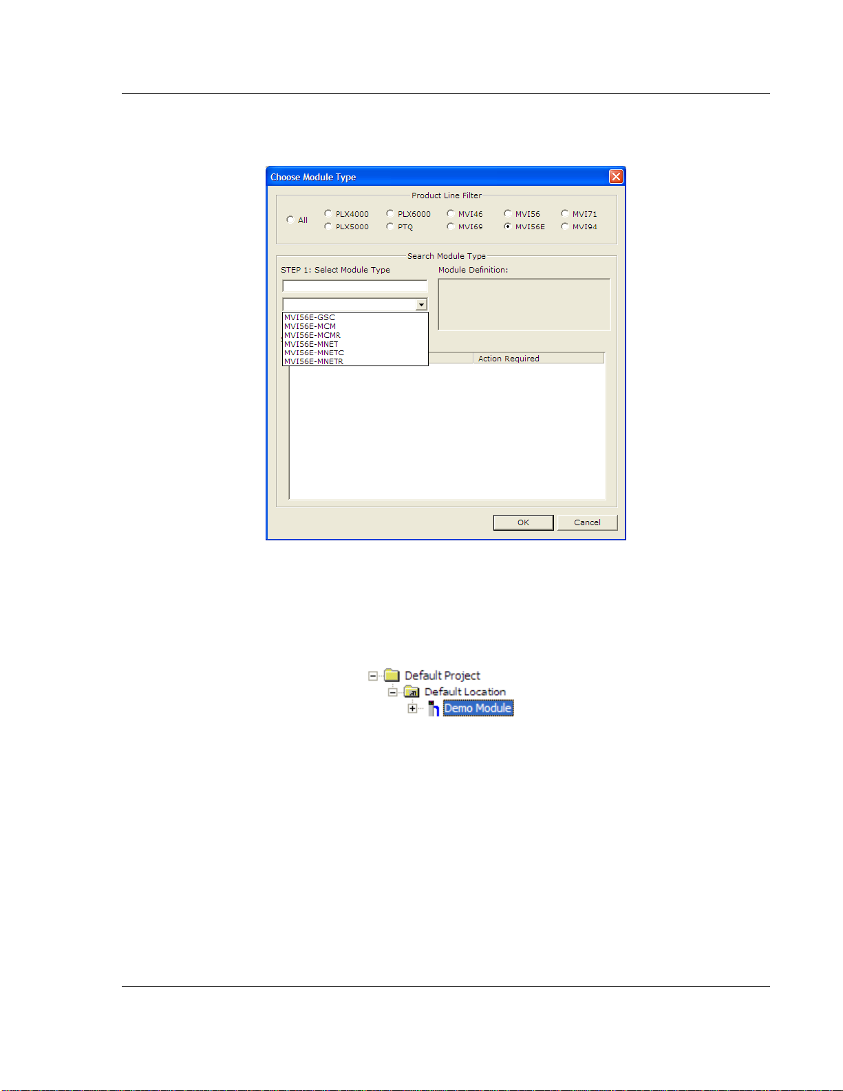
4 On the shortcut menu, choose C
HOOSE MODULE TYPE. This action opens the
CHOOSE MODULE TYPE dialog box.
5 In the P
S
ELECT MODULE TYPE dropdown list, select MVI56E-MNETR, and then click
OK
RODUCT LINE FILTER area of the dialog box, select MVI56E. In the
to save your settings and return to the ProSoft Configuration Builder
window.
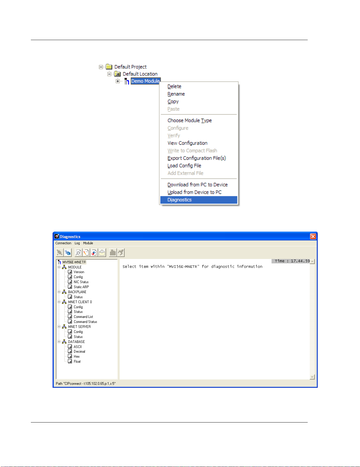
6 Right click over the module icon.
ProSoft Technology, Inc. Page 17 of 153
August 31, 2009
Page 18
MVI56E-MNETR ♦ ControlLogix Platform Start Here
Modbus TCP/IP Interface Module with Reduced Data Block User Manual
7 On the shortcut menu, choose D
IAGNOSTICS.
This action opens the D
IAGNOSTICS dialog box.
Page 18 of 153 ProSoft Technology, Inc.
August 31, 2009
Page 19
Start Here MVI56E-MNETR ♦ ControlLogix Platform
User Manual Modbus TCP/IP Interface Module with Reduced Data Block
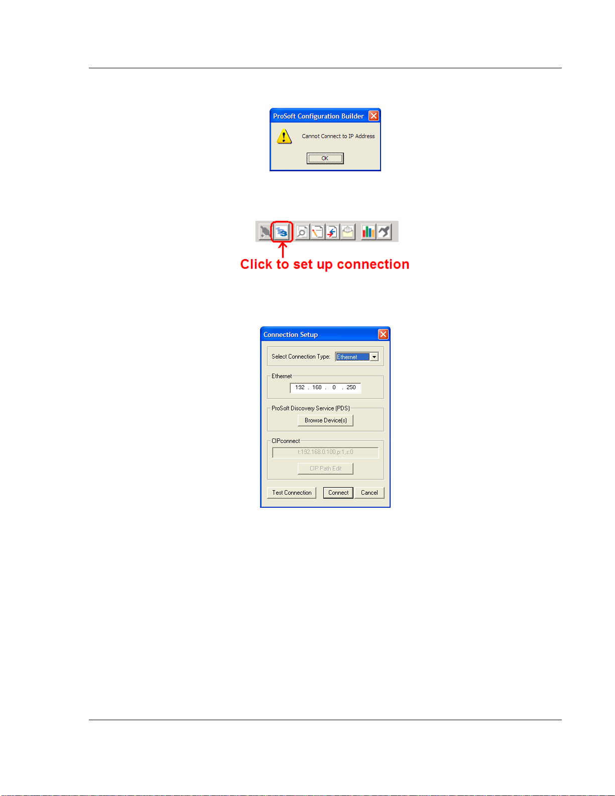
If there is no response from the module,
1 Click the S
2 On the C
ET UP CONNECTION button to browse for the module’s IP address.
ONNECTION SETUP dialog box, click the TEST CONNECTION button to
verify if the module is accessible with the current settings
3 If PCB is still unable to connect to the module, click the
BROWSE DEVICE(S)
button to open the PROSOFT DISCOVERY SERVICE.
ProSoft Technology, Inc. Page 19 of 153
August 31, 2009
Page 20
MVI56E-MNETR ♦ ControlLogix Platform Start Here
Modbus TCP/IP Interface Module with Reduced Data Block User Manual
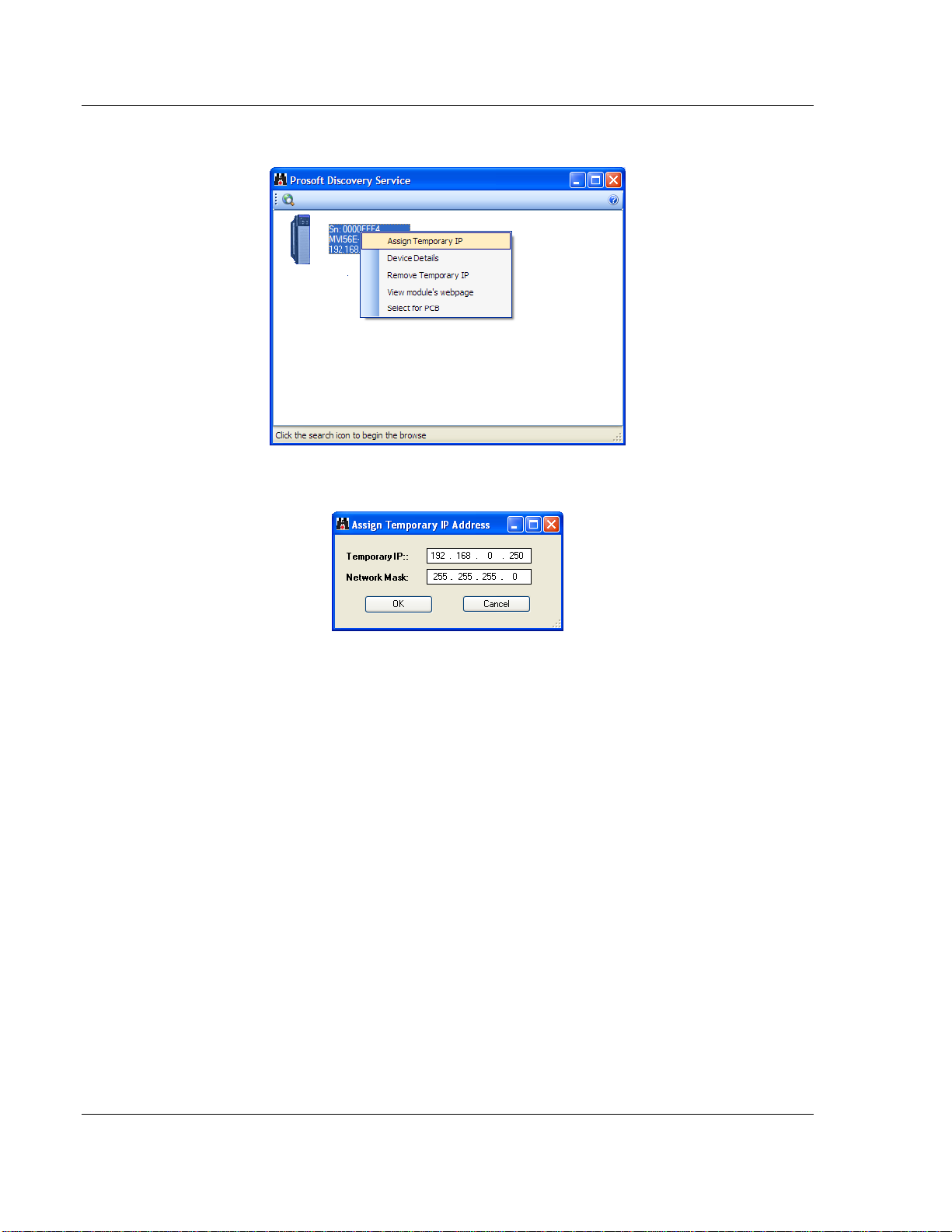
4 Select the module, then right click and choose A
SSIGN TEMPORARY IP.
5 The module’s default IP address is 192.168.0.250.
6 Choose an unused IP within your subnet, and then click OK.
Page 20 of 153 ProSoft Technology, Inc.
August 31, 2009
Page 21
Start Here MVI56E-MNETR ♦ ControlLogix Platform
User Manual Modbus TCP/IP Interface Module with Reduced Data Block
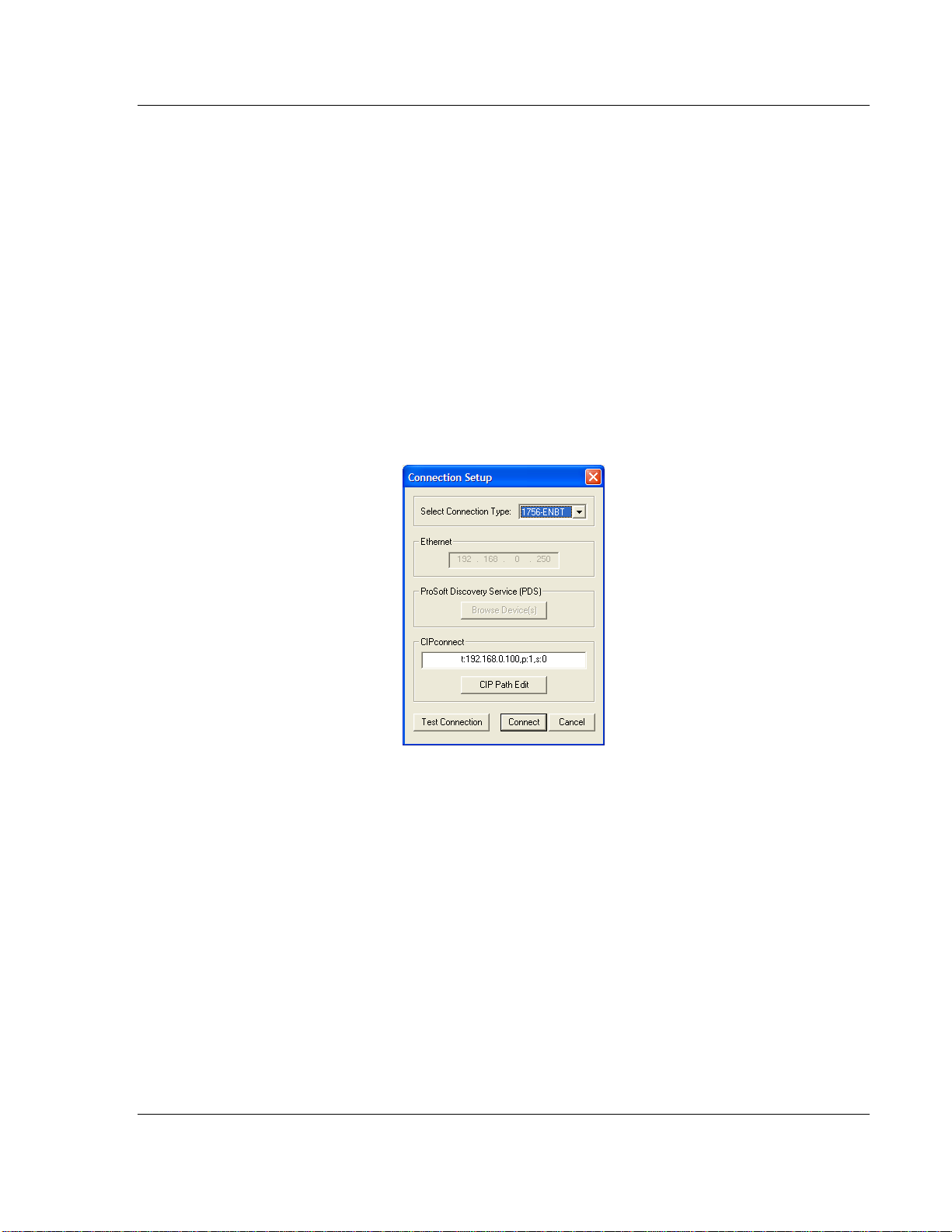
1.8.1 CIPconnect
You can use CIPconnect® to connect a PC to the MVI56E-MNETR module over
Ethernet using Rockwell Automation’s 1756-ENBT EtherNet/IP
allows you to configure the MVI56E-MNETR module and network, upload and
download files, and view network and module diagnostics from a PC. RSLinx is
not required when you use CIPconnect. All you need are:
The IP addresses and slot numbers of any 1756-ENBT modules in the path
The ControlNet node numbers and slot numbers of any 1756-CNBx
ControlNet Bridge modules in the path
The slot number of the MVI56E-MNETR in the destination ControlLogix
chassis (the last ENBT/CNBx and chassis in the path).
To use CIPconnect, follow these steps.
1 In the S
ET CONNECTION TYPE dropdown list, choose 1756-ENBT. The default
path appears in the text box, as shown in the following illustration.
®
module. This
ProSoft Technology, Inc. Page 21 of 153
August 31, 2009
Page 22
MVI56E-MNETR ♦ ControlLogix Platform Start Here
Modbus TCP/IP Interface Module with Reduced Data Block User Manual
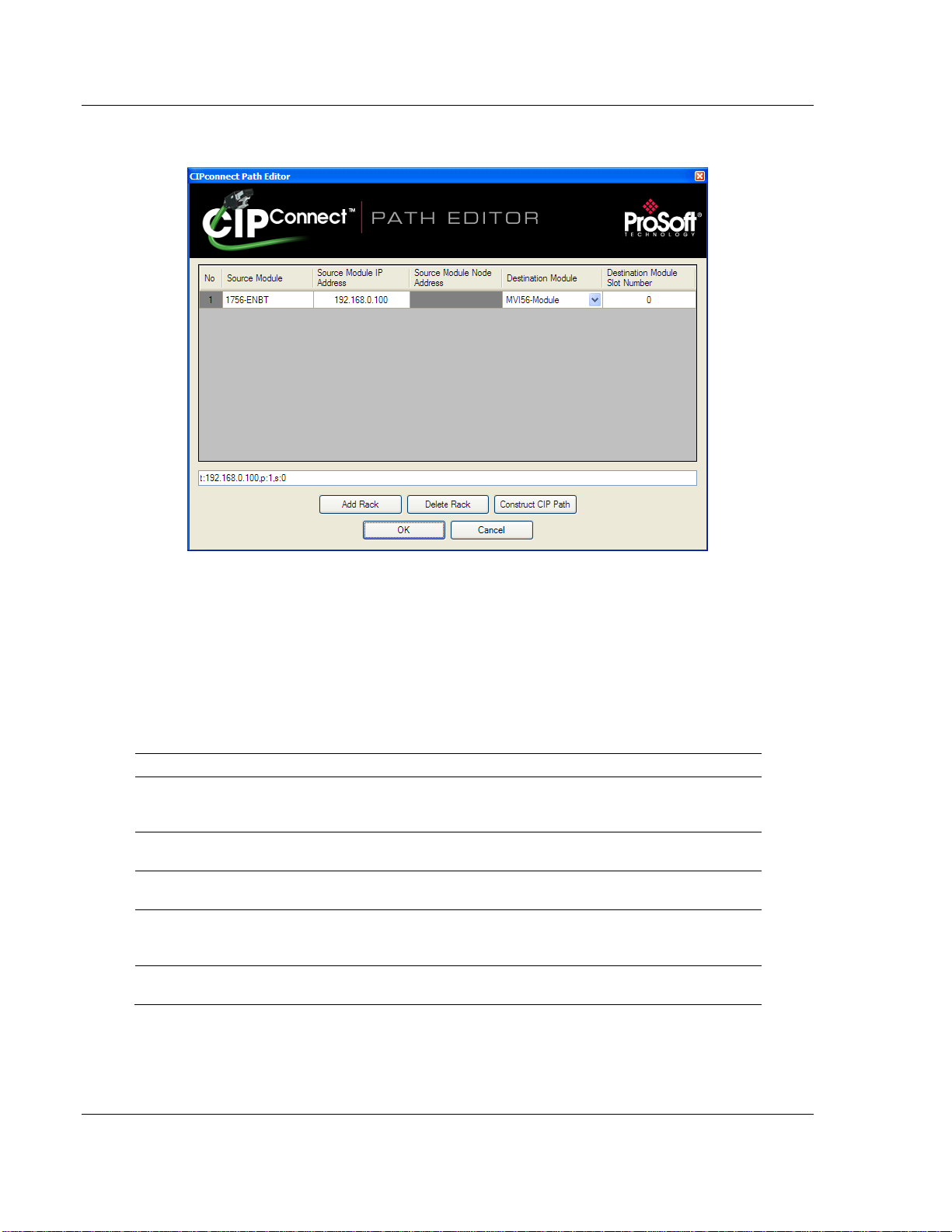
2 Click CIP
PATH EDIT to open the CIPCONNECT PATH EDITOR dialog box.
The CIP
CONNECT PATH EDITOR allows you to define the path between the PC
and the MVI56E-MNETR module. The first connection from the PC is always a
1756-ENBT (Ethernet/IP) module.
Each row corresponds to a physical rack in the CIP path.
If the MVI56E-MNETR module is located in the same rack as the first 1756-
ENBT module, select
RACK NO. 1 and configure the associated parameters.
If the MVI56E-MNETR is available in a remote rack (accessible through
ControlNet or Ethernet/IP), include all racks (by using the A
Parameter Description
Source Module
Source Module IP Address
Source Module Node Address
Destination Module
Destination Module Slot Number
Source module type. This field is automatically selected
depending on the destination module of the last rack (1756CNB or 1756-ENBT).
IP address of the source module (only applicable for 1756ENBT)
Node address of the source module (only applicable for 1756CNB)
Select the destination module associated to the source module
in the rack. The connection between the source and destination
modules is performed through the backplane.
The slot number where the destination MVI56E module is
located.
DD RACK button).
Page 22 of 153 ProSoft Technology, Inc.
August 31, 2009
Page 23
Start Here MVI56E-MNETR ♦ ControlLogix Platform
User Manual Modbus TCP/IP Interface Module with Reduced Data Block
To use the CIPconnect Path Editor, follow these steps.
1 Configure the path between the 1756-ENBT connected to your PC and the
MVI56E-MNETR module.
o If the module is located in a remote rack, add more racks to configure the
full path.
o The path can only contain ControlNet or Ethernet/IP networks.
o The maximum number of supported racks is six.
2 Click C
3 Click OK
ONSTRUCT CIP PATH to build the path in text format
to confirm the configured path.
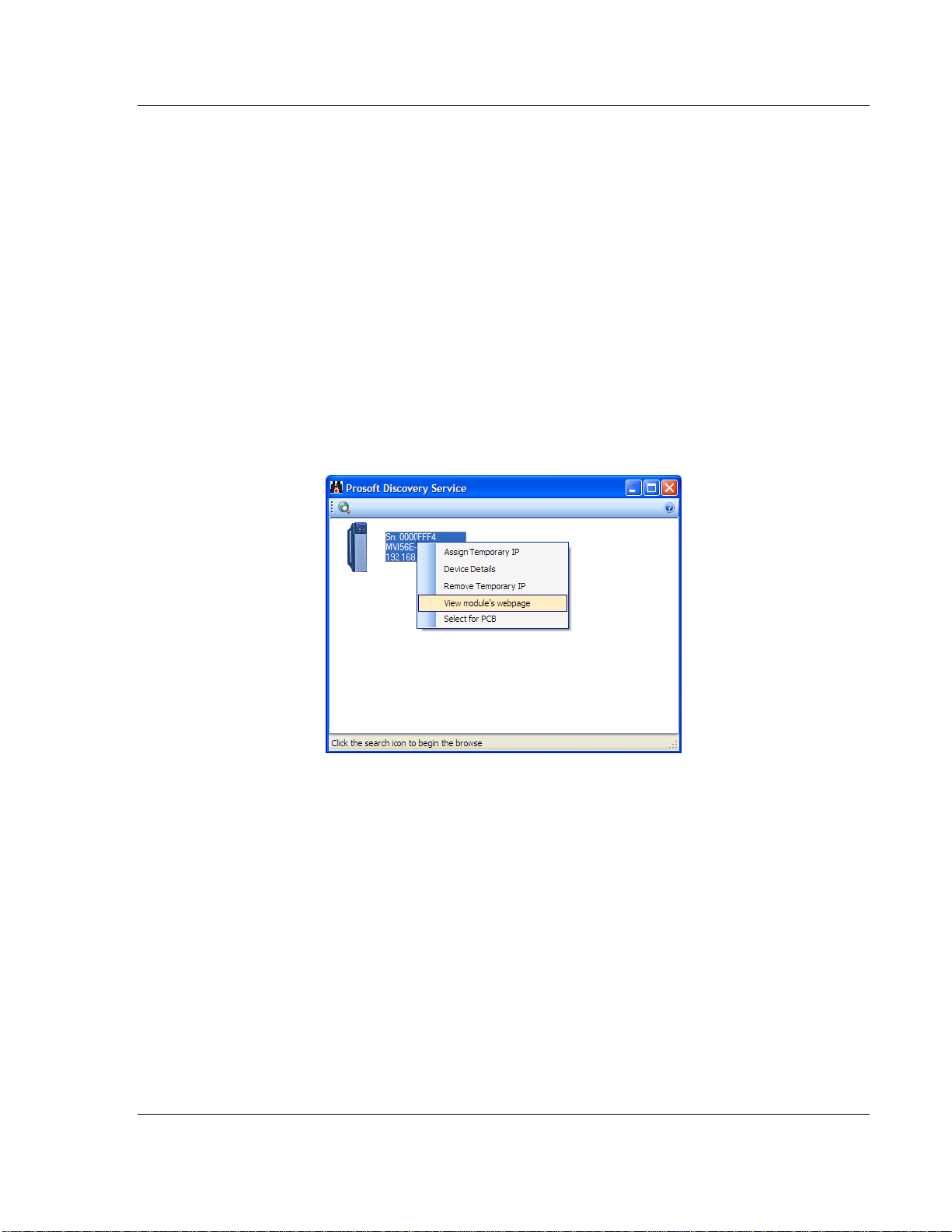
1.9 Connect to the Module's Web Page
1 In ProSoft Discovery Service, select the module to configure, and then click
the right mouse button to open a shortcut menu.
2 On the shortcut menu, choose V
IEW MODULE’S WEBPAGE.
ProSoft Technology, Inc. Page 23 of 153
August 31, 2009
Page 24
MVI56E-MNETR ♦ ControlLogix Platform Start Here
Modbus TCP/IP Interface Module with Reduced Data Block User Manual
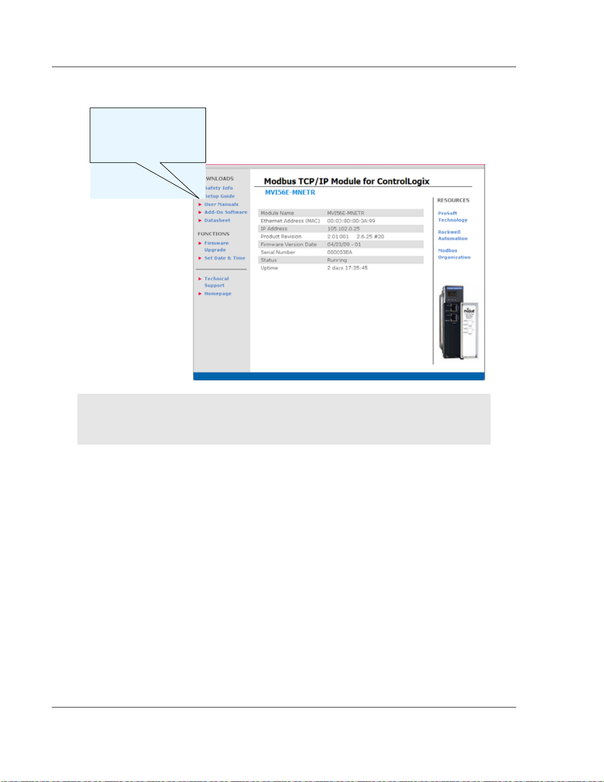
The web page contains the product documentation and sample programs.
All manuals and
configuration tools are
available from the
module’s web page
Important: The temporary IP address is only valid until the next time the module is initialized.
Please refer to the MVI56E-MNETR User Manual for information on how to set the module’s
permanent IP address.
Page 24 of 153 ProSoft Technology, Inc.
August 31, 2009
Page 25
Start Here MVI56E-MNETR ♦ ControlLogix Platform
User Manual Modbus TCP/IP Interface Module with Reduced Data Block
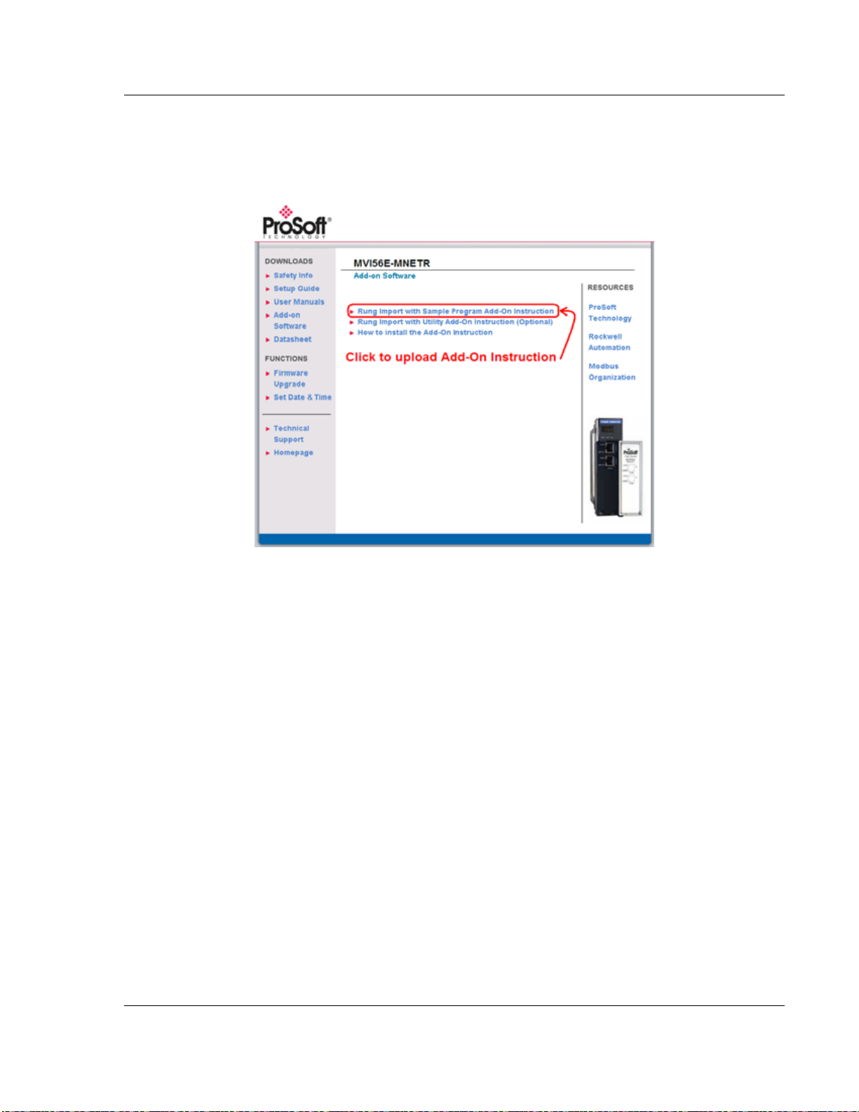
1.10 Upload the Add-On Instruction from the Module
Configuration and control information for the MVI56E-MNETR module is provided
as an Add-On Instruction for RSLogix 5000, version 16 or higher.
Two Add-On Instructions are provided:
The R
UNG IMPORT WITH SAMPLE PROGRAM ADD-ON INSTRUCTION
(MVI56(E)MNETR_AddOn_Rung_<Version #>.L5X), which includes the User
Defined Data Types, data objects and ladder logic required to configure the
MVI56E-MNETR module.
The R
UNG IMPORT WITH UTILITY ADD-ON INSTRUCTION (OPTIONAL)
(MVI56(E)MNETR_Optional_AddOn_Rung_<version #>.L5X), which includes
the data types and controller tags that allow you to update the IP address,
date and time on the module. (page
25)
ProSoft Technology, Inc. Page 25 of 153
August 31, 2009
Page 26
MVI56E-MNETR ♦ ControlLogix Platform Start Here
Modbus TCP/IP Interface Module with Reduced Data Block User Manual
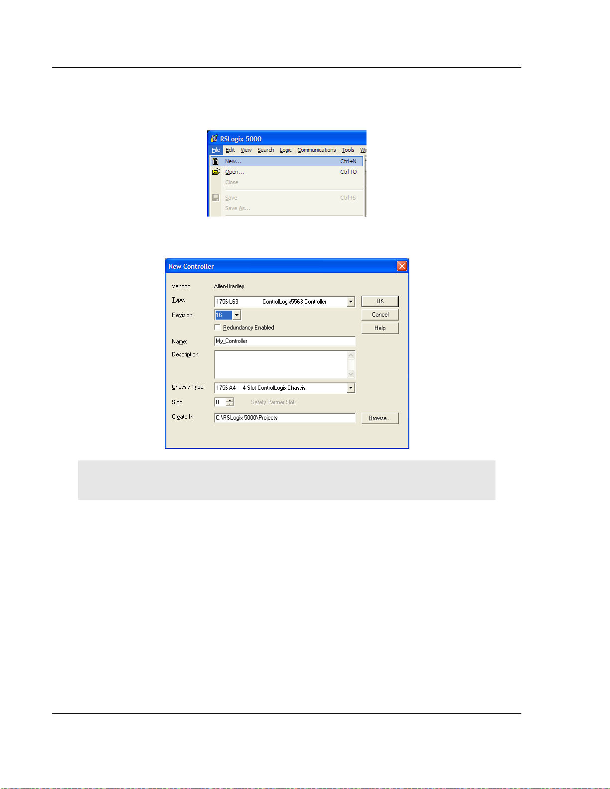
1.11 Create a new RSLogix 5000 project
1 Open the FILE menu, and then choose NEW…
2 Select R
EVISION 16.
Note. If you are installing the MVI56E-MNETR module in a remote rack, follow these steps. If you
are installing the module in a local rack, refer to Create the Module - Local Rack (page 31).
Page 26 of 153 ProSoft Technology, Inc.
August 31, 2009
Page 27

Start Here MVI56E-MNETR ♦ ControlLogix Platform
User Manual Modbus TCP/IP Interface Module with Reduced Data Block
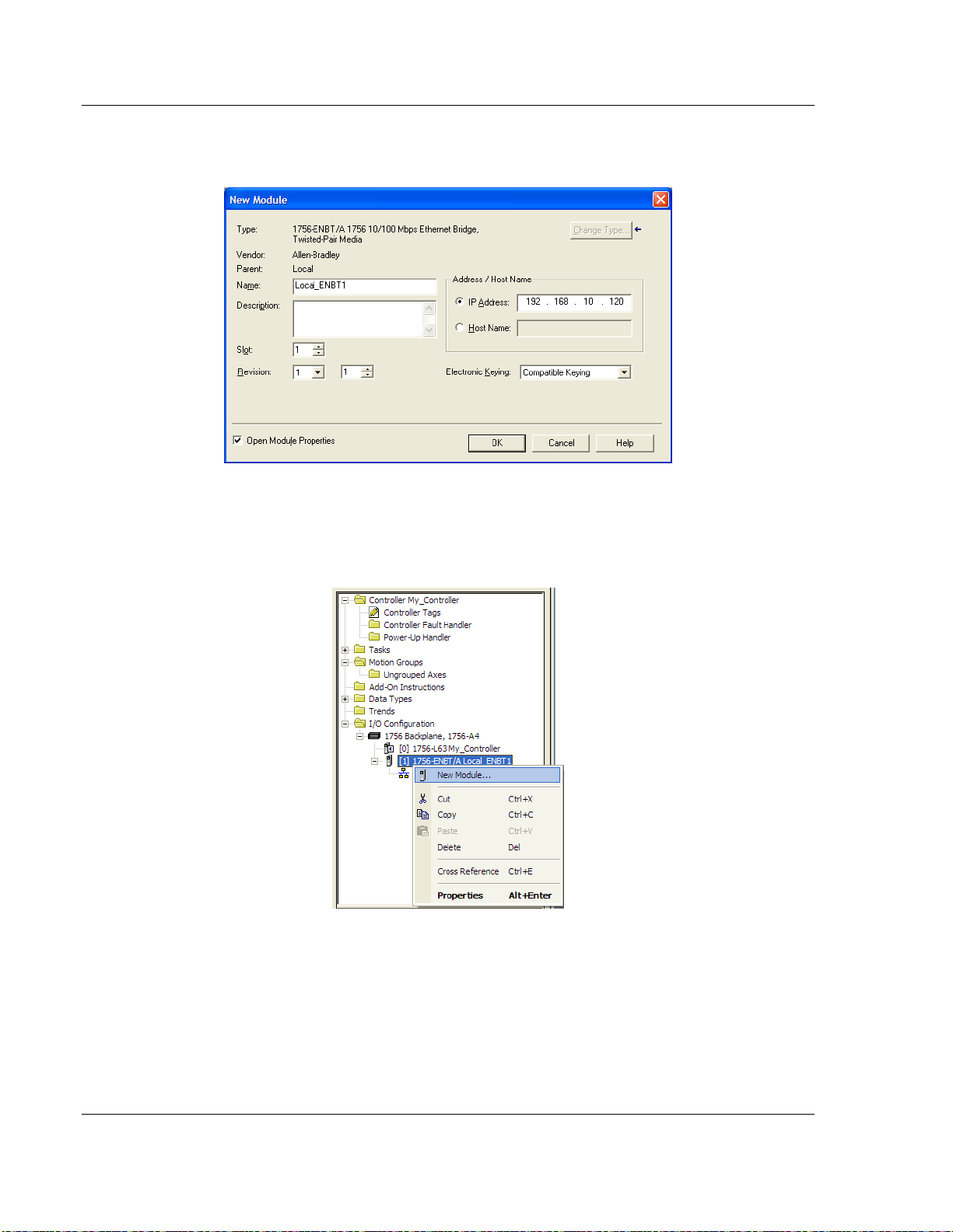
1.11.1 Create the Remote Network
1 Right-click I/O CONFIGURATION and choose NEW MODULE…
2 Expand the C
OMMUNICATIONS module selections and then select the Ethernet
Bridge module that matches your hardware. This example uses a 1756ENBT/A module.
Note: If you are prompted to "Select Major Revision", choose the lower of the available revision
numbers.
ProSoft Technology, Inc. Page 27 of 153
August 31, 2009
Page 28
MVI56E-MNETR ♦ ControlLogix Platform Start Here
Modbus TCP/IP Interface Module with Reduced Data Block User Manual
3 Name the ENBT/A module, then set the IP Address and slot location in the
local rack with the ControlLogix processor.
4 Click OK.
5 Next, select the 1756-ENBT module that you just created in the Controller
Organization pane and click the right mouse button to open a shortcut menu.
On the shortcut menu, choose N
EW MODULE.
6 Repeat steps 2 and 3 to add the second EtherNet/IP module to the remote
rack.
Page 28 of 153 ProSoft Technology, Inc.
August 31, 2009
Page 29
Start Here MVI56E-MNETR ♦ ControlLogix Platform
User Manual Modbus TCP/IP Interface Module with Reduced Data Block
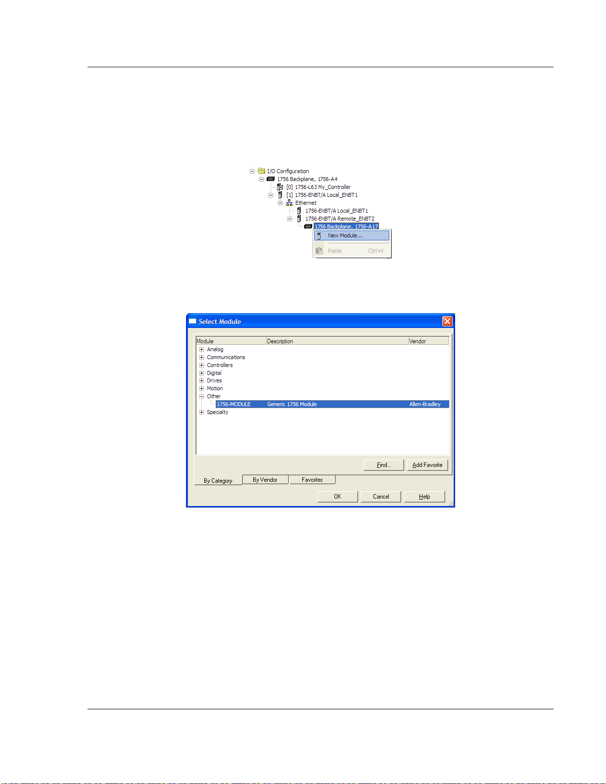
1.11.2 Create the Module - Remote Rack
1 Next, select the remote 1756 BACKPLANE node in the Controller Organization
pane underneath the remote rack EtherNet/IP module you just created and
click the right mouse button to open a shortcut menu. On the shortcut menu,
choose N
EW MODULE.
2 Expand the O
THER modules selection and then select 1756-MODULE
(GENERIC 1756 MODULE)
ProSoft Technology, Inc. Page 29 of 153
August 31, 2009
Page 30
MVI56E-MNETR ♦ ControlLogix Platform Start Here
Modbus TCP/IP Interface Module with Reduced Data Block User Manual
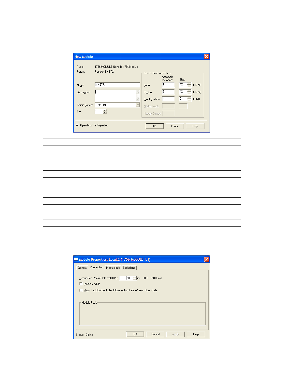
3 Set the Module Properties values as follows:
Parameter Value
Name
Description
Comm Format
Slot
Input Assembly Instance 1
Input Size 42
Output Assembly Instance 2
Output Size 42
Configuration Assembly Instance 4
Configuration Size 0
Enter a module identification string. The recommended value is
MNETR.
Enter a description for the module. Example: Modbus TCP/IP
Interface Module with Reduced Data Block.
Select D
Enter the slot number in the rack where the MVI56E-MNETR
module is or will be located.
ATA-INT (Very Important)
4 On the CONNECTION tab, set the RPI value for your project. Fifty (50)
milliseconds is usually a good starting value.
Page 30 of 153 ProSoft Technology, Inc.
August 31, 2009
Page 31

Start Here MVI56E-MNETR ♦ ControlLogix Platform
User Manual Modbus TCP/IP Interface Module with Reduced Data Block
The MVI56E-MNETR
module is now visible in the I/O CONFIGURATION section
Note. If you are installing the MVI56E-MNETR module in a local rack, follow these steps. If you are
installing the module in a remote rack, refer to Create the Module - Remote Rack (page 27).
1.11.3 Create the Module - Local Rack
1 Add the MVI56E-MNETR module to the project.
In the C
click the right mouse button to open a shortcut menu. On the shortcut menu,
choose N
ONTROLLER ORGANIZATION window, select I/O CONFIGURATION and
EW MODULE...
ProSoft Technology, Inc. Page 31 of 153
August 31, 2009
Page 32

MVI56E-MNETR ♦ ControlLogix Platform Start Here
Modbus TCP/IP Interface Module with Reduced Data Block User Manual
This action opens the S
ELECT MODULE dialog box.
2 Select the 1756-M
ODULE (GENERIC 1756 MODULE) from the list and click OK.
This action opens the NEW MODULE dialog box.
3 Set the Module Properties values as follows:
Parameter Value
Name
Description
Comm Format
Slot
Input Assembly Instance 1
Input Size 42
Output Assembly Instance 2
Enter a module identification string. The recommended value is
MNETR.
Enter a description for the module. Example: Modbus TCP/IP
Interface Module with Reduced Data Block.
Select D
Enter the slot number in the rack where the MVI56E-MNETR
module is to be installed.
ATA-INT (Very Important)
Page 32 of 153 ProSoft Technology, Inc.
August 31, 2009
Page 33

Start Here MVI56E-MNETR ♦ ControlLogix Platform
User Manual Modbus TCP/IP Interface Module with Reduced Data Block
Parameter Value
Output Size 42
Configuration Assembly Instance 4
Configuration Size 0
4 On the CONNECTION tab, set the RPI value for your project. Five (5)
milliseconds is usually a good starting value. Click OK
to confirm.
The MVI56E-MNETR
module is now visible in the I/O CONFIGURATION section
ProSoft Technology, Inc. Page 33 of 153
August 31, 2009
Page 34

MVI56E-MNETR ♦ ControlLogix Platform Start Here
Modbus TCP/IP Interface Module with Reduced Data Block User Manual
1.11.4 Import Add-On Instruction
1 In the CONTROLLER ORGANIZATION window, expand the TASKS folder and
subfolder until you reach the M
2 In the M
AINPROGRAM folder, double-click to open the MAINROUTINE ladder.
3 Select an empty rung in the new routine, and then click the right mouse
button to open a shortcut menu. On the shortcut menu, choose I
RUNG…
AINPROGRAM folder.
MPORT
Page 34 of 153 ProSoft Technology, Inc.
August 31, 2009
Page 35

Start Here MVI56E-MNETR ♦ ControlLogix Platform
User Manual Modbus TCP/IP Interface Module with Reduced Data Block
4 Navigate to the location on your PC where you saved (page
25) the Add-On
Instruction (for example, "My Documents" or "Desktop"). Select the
MVI56(E)MNETR_A
DDON_RUNG_<VERSION #>.L5X file
This action opens the I
MPORT CONFIGURATION dialog box, showing the
controller tags that will be created.
ProSoft Technology, Inc. Page 35 of 153
August 31, 2009
Page 36

MVI56E-MNETR ♦ ControlLogix Platform Start Here
Modbus TCP/IP Interface Module with Reduced Data Block User Manual
o If you are installing the module in a Remote Rack, open the dropdown
menus for the Input and Output tags, and select the MNETR module in
the remote rack.
Page 36 of 153 ProSoft Technology, Inc.
August 31, 2009
Page 37

Start Here MVI56E-MNETR ♦ ControlLogix Platform
User Manual Modbus TCP/IP Interface Module with Reduced Data Block
o If you are installing the module in a Local Rack, verify that the slot number
is correct for the module.
5 Click OK
progress:
to confirm the import. RSLogix will indicate that the import is in
ProSoft Technology, Inc. Page 37 of 153
August 31, 2009
Page 38

MVI56E-MNETR ♦ ControlLogix Platform Start Here
Modbus TCP/IP Interface Module with Reduced Data Block User Manual
When the import is complete, you will see the new Add-On Instruction rung in the
ladder.
The procedure has also imported new User Defined Data Types, data objects
and the Add-On instruction for your project.
Page 38 of 153 ProSoft Technology, Inc.
August 31, 2009
Page 39

Start Here MVI56E-MNETR ♦ ControlLogix Platform
User Manual Modbus TCP/IP Interface Module with Reduced Data Block
1.11.5 Connect your PC to the ControlLogix Processor
There are several ways to establish communication between your PC and the
ControlLogix processor. The following steps show how to establish
communication through the serial interface. Refer to your Rockwell Automation
documentation for information on other connection methods.
1 Connect the right-angle connector end of the cable to your controller at the
communications port.
2 Connect the straight connector end of the cable to the serial port on your
computer.
ProSoft Technology, Inc. Page 39 of 153
August 31, 2009
Page 40

MVI56E-MNETR ♦ ControlLogix Platform Start Here
Modbus TCP/IP Interface Module with Reduced Data Block User Manual
1.11.6 Adding Multiple Modules (Optional)
Important: If your application requires more than one MVI56-MNETR module into the same
project, follow the steps below.
1 In the I/O Configuration folder, click the right mouse button to open a shortcut
menu, and then choose N
2 Select 1756-MODULE
EW MODULE.
This action opens the New Module dialog box.
Page 40 of 153 ProSoft Technology, Inc.
August 31, 2009
Page 41

Start Here MVI56E-MNETR ♦ ControlLogix Platform
User Manual Modbus TCP/IP Interface Module with Reduced Data Block
3 Fill in the module properties as follows:
Parameter Value
Name Enter a module identification string. Example: MNETR_2
Description
Comm Format Select DATA-INT
Slot
Input Assembly
Instance
Input Size 42
Output Assembly
Instance
Output Size 42
Configuration
Assembly Instance
Configuration Size 0
Enter a description for the module. Example: Modbus TCP/IP Interface
Module with Reduced Data Block
Enter the slot number in the rack where the ModelNumber> module is
located.
1
2
4
4 Click OK to confirm. The new module is now visible:
5 Expand the Tasks folder, and then expand the MainTask folder.
6 On the MainProgram folder, click the right mouse button to open a shortcut
menu. On the shortcut menu, choose N
EW ROUTINE.
7 In the New Routine dialog box, enter the name and description of your
routine, and then click OK.
ProSoft Technology, Inc. Page 41 of 153
August 31, 2009
Page 42

MVI56E-MNETR ♦ ControlLogix Platform Start Here
Modbus TCP/IP Interface Module with Reduced Data Block User Manual
8 Select an empty rung in the new routine, and then click the right mouse
button to open a shortcut menu. On the shortcut menu, choose "I
MPORT
RUNG…".
Page 42 of 153 ProSoft Technology, Inc.
August 31, 2009
Page 43

Start Here MVI56E-MNETR ♦ ControlLogix Platform
User Manual Modbus TCP/IP Interface Module with Reduced Data Block
9 Select the file MVI56(E)MNETR_AddOn_Rung_<Version #>.L5X
This action opens the I
MPORT CONFIGURATION dialog box, showing the
controller tags that will be created.
ProSoft Technology, Inc. Page 43 of 153
August 31, 2009
Page 44

MVI56E-MNETR ♦ ControlLogix Platform Start Here
Modbus TCP/IP Interface Module with Reduced Data Block User Manual
10 Associate the I/O connection variables to the correct module. The default
values are Local:1:I and Local:1:O so these require change.
Page 44 of 153 ProSoft Technology, Inc.
August 31, 2009
Page 45

Start Here MVI56E-MNETR ♦ ControlLogix Platform
User Manual Modbus TCP/IP Interface Module with Reduced Data Block
Change the default tags MNETR and AOI56MNETR to avoid conflict with
existing tags. This procedure will append the string "_2" as follows:
Or, in a Remote Rack application…
ProSoft Technology, Inc. Page 45 of 153
August 31, 2009
Page 46

MVI56E-MNETR ♦ ControlLogix Platform Start Here
Modbus TCP/IP Interface Module with Reduced Data Block User Manual
11 Click OK to confirm.
Page 46 of 153 ProSoft Technology, Inc.
August 31, 2009
Page 47

Start Here MVI56E-MNETR ♦ ControlLogix Platform
User Manual Modbus TCP/IP Interface Module with Reduced Data Block
Or, in a Remote Rack application…
The setup procedure is now complete. Save the project and download the
application to your ControlLogix processor.
ProSoft Technology, Inc. Page 47 of 153
August 31, 2009
Page 48

MVI56E-MNETR ♦ ControlLogix Platform Start Here
Modbus TCP/IP Interface Module with Reduced Data Block User Manual
1.11.7 Download the Sample Program to the Processor
Note: The key switch on the front of the ControlLogix processor must be in the REM or PROG
position.
1 If you are not already online with the processor, open the COMMUNICATIONS
menu, and then choose DOWNLOAD. RSLogix will establish communication
with the processor.
2 When communication is established, RSLogix will open a confirmation dialog
box. Click the D
processor.
OWNLOAD button to transfer the sample program to the
3 RSLogix will compile the program and transfer it to the processor. This
process may take a few minutes.
4 When the download is complete, RSLogix will open another confirmation
dialog box. If the keyswitch is in the REM position, click OK
processor from P
ROGRAM mode to RUN mode.
to switch the
Note: If you receive an error message during these steps, refer to your RSLogix documentation to
interpret and correct the error.
Page 48 of 153 ProSoft Technology, Inc.
August 31, 2009
Page 49

Configuring the MVI56E-MNETR Module MVI56E-MNETR ♦ ControlLogix Platform
User Manual Modbus TCP/IP Interface Module with Reduced Data Block
2 Configuring the MVI56E-MNETR Module
In This Chapter
Using ProSoft Configuration Builder Software.......................................49
Download the Project to the Module......................................................67
Using CIPconnect® to Connect to the Module.......................................68
2.1 Using ProSoft Configuration Builder Software
ProSoft Configuration Builder (PCB) provides a quick and easy way to manage
module configuration files customized to meet your application needs. PCB is not
only a powerful solution for new configuration files, but also allows you to import
information from previously installed (known working) configurations to new
projects.
Note: The MVI56E-MNETR module receives its protocol and backplane configuration information
from the Personality Module (Compact Flash). Use ProSoft Configuration Builder to configure
module settings, and to download changes to the Personality Module.
2.1.1 Set Up the Project
To begin, start PROSOFT CONFIGURATION BUILDER (PCB).
ProSoft Technology, Inc. Page 49 of 153
August 31, 2009
Page 50

MVI56E-MNETR ♦ ControlLogix Platform Configuring the MVI56E-MNETR Module
Modbus TCP/IP Interface Module with Reduced Data Block User Manual
If you have used other Windows configuration tools before, you will find the
screen layout familiar. PCB’s window consists of a tree view on the left, and an
information pane and a configuration pane on the right side of the window. When
you first start PCB, the tree view consists of folders for D
EFAULT LOCATION, with a DEFAULT MODULE in the Default Location folder. The
D
EFAULT PROJECT and
following illustration shows the PCB window with a new project.
Page 50 of 153 ProSoft Technology, Inc.
August 31, 2009
Page 51

Configuring the MVI56E-MNETR Module MVI56E-MNETR ♦ ControlLogix Platform
User Manual Modbus TCP/IP Interface Module with Reduced Data Block
Your first task is to add the MVI56E-MNETR module to the project.
1 Use the mouse to select D
EFAULT MODULE in the tree view, and then click the
right mouse button to open a shortcut menu.
2 On the shortcut menu, choose C
HOOSE MODULE TYPE. This action opens the
CHOOSE MODULE TYPE dialog box.
3 In the P
S
ELECT MODULE TYPE dropdown list, select MVI56E-MNETR, and then click
OK
RODUCT LINE FILTER area of the dialog box, select MVI56E. In the
to save your settings and return to the ProSoft Configuration Builder
window.
ProSoft Technology, Inc. Page 51 of 153
August 31, 2009
Page 52

MVI56E-MNETR ♦ ControlLogix Platform Configuring the MVI56E-MNETR Module
Modbus TCP/IP Interface Module with Reduced Data Block User Manual
2.1.2 Set Module Parameters
The next task is to configure module parameters. Notice that the contents of the
information pane and the configuration pane changed when you added the
MVI56E-MNETR module to the project.
At this time, you may wish to rename the "Default Project" and "Default Location"
folders in the tree view.
To rename an object:
1 Select the object, and then click the right mouse button to open a shortcut
menu. From the shortcut menu, choose R
ENAME.
2 Type the name to assign to the object.
3 Click away from the object to save the new name.
Configuring Module Parameters
1 Click on the plus sign next to the
2 Double-click the
icon to open the EDIT dialog box.
icon to expand module information.
3 To edit a parameter, select the parameter in the left pane and make your
changes in the right pane.
4 Click OK
to save your changes.
Page 52 of 153 ProSoft Technology, Inc.
August 31, 2009
Page 53

Configuring the MVI56E-MNETR Module MVI56E-MNETR ♦ ControlLogix Platform
User Manual Modbus TCP/IP Interface Module with Reduced Data Block
Printing a Configuration File
1 Select the M
ODULE icon, and then click the right mouse button to open a
shortcut menu.
2 On the shortcut menu, choose V
V
IEW CONFIGURATION window.
3 On the V
P
RINT. This action opens the PRINT dialog box.
4 On the P
IEW CONFIGURATION window, open the FILE menu, and choose
RINT dialog box, choose the printer to use from the dropdown list,
select printing options, and then click OK.
IEW CONFIGURATION. This action opens the
2.1.3 [Module]
This section of the configuration describes the database setup and module level
parameters. This section provides the module with a unique name, identifies the
method of failure for the communications for the module if the processor is not in
run, and describes how to initialize the module upon startup.
Error/Status Pointer
-1 to 4955
Starting register location in virtual Modbus database for the error/status table. If a
value of -1 is entered, the error/status data will not be placed in the database. All
other valid values determine the starting location of the data. This data area
includes the module version information and all error/status data.
Read Register Start
0 to 4999
This parameter specifies the starting register in the module where data will be
transferred from the module to the processor. Valid range for this parameter is 0
to 4999.
Read Register Count
0 to 5000
This parameter specifies the number of registers to be transferred from the
module to the processor. Valid entry for this parameter is 0 to 5000.
Write Register Start
0 to 4999
This parameter specifies the starting register in the module where the data will be
transferred from the processor to the module. Valid range for this parameter is 0
to 4999.
Write Register Count
0 to 5000
This parameter specifies the number of registers to transfer from the processor to
the module. Valid entry for this parameter is 0 to 5000 words.
ProSoft Technology, Inc. Page 53 of 153
August 31, 2009
Page 54

MVI56E-MNETR ♦ ControlLogix Platform Configuring the MVI56E-MNETR Module
Modbus TCP/IP Interface Module with Reduced Data Block User Manual
Failure Flag Count
0 through 65535
This parameter specifies the number of successive transfer errors that must
occur before halting communication on the application port(s). If the parameter is
set to 0, the application port(s) will continue to operate under all conditions. If the
value is set larger than 0 (1 to 65535), communications will cease if the specified
number of failures occur.
Initialize Output Data
0 = No
1 = Yes
This parameter is used to determine if the output data for the module should be
initialized with values from the processor. If the value is set to 0, the output data
will be initialized to 0. If the value is set to 1, the data will be initialized with data
from the processor. Use of this option requires associated ladder logic to pass
the data from the processor to the module.
Pass-Through Mode
0, 1, 2 or 3
This parameter specifies the pass-through mode for write messages received by
the MNET and MBAP server ports.
If the parameter is set to 0, all write messages will be placed in the module’s
virtual database.
If a value of 1 is entered, write messages received will be sent to the
processor as unformatted messages.
If a value of 2 is entered, write messages received will be sent to the
processor as formatted messages.
If a value of 3 is entered, write messages received will be sent to the
processor with the bytes swapped in a formatted message.
Duplex/Speed Code
0, 1, 2, 3 or 4
This parameter allows you to force the module to use a specific duplex and
speed setting.
Value = 1: Half duplex, 10 MB speed
Value = 2: Full duplex, 10 MB speed
Value = 3: Half duplex, 100 MB speed
Value = 4: Full duplex, 100 MB speed
Value = 0: Auto negotiate.
Auto Negotiate is the default value for backward compatibility. This feature is not
implemented in older software revisions.
Page 54 of 153 ProSoft Technology, Inc.
August 31, 2009
Page 55

Configuring the MVI56E-MNETR Module MVI56E-MNETR ♦ ControlLogix Platform
User Manual Modbus TCP/IP Interface Module with Reduced Data Block
2.1.4 [MNET Client x]
This section defines general configuration for the MNET Client (Master).
Error/Status Pointer
-1 to 4990
Starting register location in virtual database for the error/status table for this
client. If a value of -1 is entered, the error/status data will not be placed in the
database. All other valid values determine the starting location of the data.
Command Error Pointer
-1 to 4999
This parameter sets the address in the internal database where the command
error data will be placed. If the value is set to -1, the data will not be transferred
to the database.
Minimum Command Delay
0 to 65535
This parameter specifies the number of milliseconds to wait between the initial
issuance of a command. This parameter can be used to delay all commands sent
to slaves to avoid "flooding" commands on the network. This parameter does not
affect retries of a command as they will be issued when failure is recognized.
Response Timeout
0 to 65535 milliseconds
This is the time in milliseconds that a client will wait before re-transmitting a
command if no response is received from the addressed server. The value to use
depends upon the type of communication network used, and the expected
response time of the slowest device on the network.
Retry Count
0 to 10
This parameter specifies the number of times a command will be retried if it fails.
Float Flag
Yes or No
This flag specifies how the Slave driver will respond to Function Code 3, 6, and
16 commands (read and write Holding Registers) from a remote Master when it
is moving 32-bit floating-point data.
If the remote Master expects to receive or will send one, complete, 32-bit
floating-point value for each count of one (1), then set this parameter to Y
ES,
especially if the Master must read or write from Modbus addresses above
ProSoft Technology, Inc. Page 55 of 153
August 31, 2009
Page 56

MVI56E-MNETR ♦ ControlLogix Platform Configuring the MVI56E-MNETR Module
Modbus TCP/IP Interface Module with Reduced Data Block User Manual
gateway address 3999 (virtual Modbus address 44000 or 440000). When set to
Y
ES, the Slave driver will return values from two, consecutive, 16-bit internal
memory registers (32 total bits) for each count in the read command or receive
32-bits per count from the Master for write commands. Example: Count = 10,
Slave driver will send 20 16-bit registers for 10 total 32-bit floating-point values.
If, however, the remote Master sends a count of two (2) for each 32-bit floatingpoint value it expects to receive or send, or, if you do not plan to use floatingpoint data in your application, then set this parameter to N
O, which is the default
setting.
You will also need to set the Float Start and Float Offset parameters to
appropriate values whenever the Float Flag parameter is set to Y
ES.
Float Start
0 to 65535
This parameter defines the first register of floating-point data. All requests with
register values greater-than or equal to this value will be considered floating-point
data requests. This parameter is only used if the Float Flag is enabled. For
example, if a value of 7000 is entered, all requests for registers 7000 and above
will be considered as floating-point data.
Float Offset
0 to 9999
This parameter defines the start register for floating-point data in the internal
database. This parameter is used only if the Float Flag is enabled. For example,
if the Float Offset value is set to 3000 and the float start parameter is set to 7000,
data requests for register 7000 will use the internal Modbus register 3000.
ARP Timeout
1 to 60
This parameter specifies the number of seconds to wait for an ARP reply after a
request is issued.
Command Error Delay
0 to 300
This parameter specifies the number of 100 millisecond intervals to turn off a
command in the error list after an error is recognized for the command. If this
parameter is set to 0, there will be no delay.
Page 56 of 153 ProSoft Technology, Inc.
August 31, 2009
Page 57

Configuring the MVI56E-MNETR Module MVI56E-MNETR ♦ ControlLogix Platform
User Manual Modbus TCP/IP Interface Module with Reduced Data Block
2.1.5 [MNET Client x Commands]
The [MNET CLIENT X COMMANDS] section of the configuration sets the Modbus
TCP/IP Client command list. This command list polls Modbus TCP/IP Server
devices attached to the Modbus TCP/IP Client port. The module supports
numerous commands. This permits the module to interface with a wide variety of
Modbus TCP/IP protocol devices.
The function codes used for each command are those specified in the Modbus
protocol (page
part of the record contains the information relating to the MVI56E-MNETR
communication module, and the second part contains information required to
interface to the Modbus TCP/IP Server device.
121). Each command list record has the same format. The first
Command List Overview
In order to interface the MVI56E-MNETR module with Modbus TCP/IP Server
devices, you must construct a command list. The commands in the list specify
the Server device to be addressed, the function to be performed (read or write),
the data area in the device to interface with and the registers in the internal
database to be associated with the device data. The Client command list
supports up to 100 commands.
The command list is processed from top (command #0) to bottom. A poll interval
parameter is associated with each command to specify a minimum delay time in
tenths of a second between the issuance of a command. If the user specifies a
value of 10 for the parameter, the command will be executed no more frequently
than every 1 second.
Write commands have a special feature, as they can be set to execute only if the
data in the write command changes. If the register data values in the command
have not changed since the command was last issued, the command will not be
executed.
If the data in the command has changed since the command was last issued, the
command will be executed. Use of this feature can lighten the load on the
network. In order to implement this feature; set the enable code for the command
to a value of 2.
ProSoft Technology, Inc. Page 57 of 153
August 31, 2009
Page 58

MVI56E-MNETR ♦ ControlLogix Platform Configuring the MVI56E-MNETR Module
Modbus TCP/IP Interface Module with Reduced Data Block User Manual
Command Entry Formats
The following table shows the structure of the configuration data necessary for
each of the supported commands.
Column # 1 2 3 4 5 6 7 8 9 10
Function
Code
fc1 Code Register
fc2 Code Register
fc3 Code Register 1/10th
fc4 Code Register 1/10th
fc5 Code 1 bit 1/10th
fc6 Code 1 bit 1/10th
fc15 Code Register
fc16 Code Register 1/10th
Enable
Code
Internal
Address
(bit)
(bit)
(bit)
Poll
Interval
Time
1/10th
Seconds
1/10th
Seconds
Seconds
Seconds
Seconds
Seconds
1/10th
Seconds
Seconds
Count Swap
Code
Bit
Count
Bit
Count
Word
Count
Word
Count
Bit
Count
Word
Count
Bit
Count
Word
Count
0 IP
0 IP
Code IP
0 IP
0 IP
0 IP
0 IP
0 IP
IP
Address
Address
Address
Address
Address
Address
Address
Address
Address
Serv
Port
Port # Address Read Coil
Port # Address Read Input
Port # Address Read Holding
Port # Address Read Input
Port # Address Force (Write)
Port # Address Preset (Write)
Port # Address Force (Write)
Port # Address Preset (Write)
Slave
Node
Function
Code
(0x)
(1x)
Registers
(4x)
Registers
(3x)
Single Coil
(0x)
Single
Register (4x)
Multiple Coil
(0x)
Multiple
Register (4x)
Device
Modbus
Address
Register
Register
Register
Register
Register
Register
Register
Register
The first part of the record is the module Information, which relates to the
MVI56E module and the second part contains information required to interface to
the Server device.
Page 58 of 153 ProSoft Technology, Inc.
August 31, 2009
Page 59

Configuring the MVI56E-MNETR Module MVI56E-MNETR ♦ ControlLogix Platform
User Manual Modbus TCP/IP Interface Module with Reduced Data Block
Command list example:
Enable
Yes, No, or Conditional
This field defines whether the command is to be executed and under what
conditions.
Value Description
0 The command is disabled and will not be executed in the normal polling sequence.
1
2
The command is executed each scan of the command list if the Poll Interval Time is
set to zero. If the Poll Interval time is set, the command will be executed, when the
interval timer expires.
The command will execute only if the internal data associated with the command
changes. This value is valid only for write commands.
Internal Address
0 to 4999 (for word-level addressing)
or
0 to 65535 (for bit-level addressing)
This field specifies the database address in the module's internal database to use
as the destination for data brought in by a read command or as the source for
data to be sent out by a write command. The database address is interpreted as
a bit address or a 16-bit word (register) address, depending on the Modbus
Function Code used in the command.
For Modbus functions 1, 2, 5, and 15, this parameter is interpreted as a bit-
level address.
For Modbus functions 3, 4, 6, and 16, this parameter is interpreted as a word-
or register-level address.
ProSoft Technology, Inc. Page 59 of 153
August 31, 2009
Page 60

MVI56E-MNETR ♦ ControlLogix Platform Configuring the MVI56E-MNETR Module
Modbus TCP/IP Interface Module with Reduced Data Block User Manual
Poll Interval
0 to 65535
This parameter specifies the minimum interval to execute continuous commands
(Enable code of 1). The parameter is entered in tenths of a second. Therefore, if
a value of 100 is entered for a command, the command executes no more
frequently than every 10 seconds.
Reg Count
Regs: 1 to 125
Coils: 1 to 800
This parameter specifies the number of 16-bit registers or binary bits to be
transferred by the command.
Functions 5 and 6 ignore this field as they apply only to a single data point.
For functions 1, 2, and 15, this parameter sets the number of bits (inputs or
coils) to be transferred by the command.
For functions 3, 4, and 16, this parameter sets the number of registers to be
transferred by the command.
Swap Code
No Change
Word Swap
Word and Byte Swap
Byte Swap
This parameter defines if and how the order of bytes in data received or sent is to
be rearranged. This option exists to allow for the fact that different manufacturers
store and transmit multi-byte data in different combinations that do other
manufacturers. This parameter is helpful when dealing with floating-point or other
multi-byte values, as there is no one standard method of storing these data
types. This parameter can be set to rearrange the byte order of data received or
sent into order more useful or convenient for other applications. The following
table defines the valid Swap Code values and the effect they have on the byteorder of the data.
Swap Code Description
None No Change is made in the byte ordering (1234 = 1234)
Swap Words The words are swapped (1234=3412)
Swap Words & Bytes
Swap Bytes The bytes in each word are swapped (1234=2143)
The words are swapped then the bytes in each word are swapped
(1234=4321)
These swap operations affect 4-byte (or 2-word) groups of data. Therefore, data
swapping using these Swap Codes should be done only when using an even
number of words, such as when 32-bit integer or floating-point data is involved.
Page 60 of 153 ProSoft Technology, Inc.
August 31, 2009
Page 61

Configuring the MVI56E-MNETR Module MVI56E-MNETR ♦ ControlLogix Platform
User Manual Modbus TCP/IP Interface Module with Reduced Data Block
Node IP Address
xxx.xxx.xxx.xxx
The IP address of the device being addressed by the command.
Service Port
502 or other supported ports on server
Use a value of 502 when addressing Modbus TCP/IP servers that are compatible
with the Schneider Electric MBAP specifications (this will be most devices). If a
server implementation supports another service port, enter the value here.
Slave Address
0 - Broadcast to all nodes
1 to 255
Use this parameter to specify the slave address of a remote Modbus Serial
device through a Modbus Ethernet to Serial converter.
Note: Use the Node IP Address parameter (page 61) to address commands to a remote Modbus
TCP/IP device.
Note: Most Modbus devices accept an address in the range of only 1 to 247, so check with slave
device manufacturer to see if a particular slave can use addresses 248-255.
If the value is set to zero, the command will be a broadcast message on the network. The Modbus
protocol permits broadcast commands for write operations. Do not use node address 0 for read
operations.
Modbus Function
1, 2, 3, 4, 5, 6, 15, or 16
This parameter specifies the Modbus Function Code to be executed by the
command. These function codes are defined in the Modbus protocol. The
following table lists the purpose of each function supported by the module. More
information on the protocol is available from www.modbus.org.
Modbus Function Code Description
1 Read Coil Status
2 Read Input Status
3 Read Holding Registers
4 Read Input Registers
5 Force (Write) Single Coil
6 Preset (Write) Single Register
15 Force Multiple Coils
16 Preset Multiple Registers
ProSoft Technology, Inc. Page 61 of 153
August 31, 2009
Page 62

MVI56E-MNETR ♦ ControlLogix Platform Configuring the MVI56E-MNETR Module
Modbus TCP/IP Interface Module with Reduced Data Block User Manual
MB Address in Device
This parameter specifies the starting Modbus register or bit address in the slave
to be used by the command. Refer to the documentation of each Modbus slave
device for the register and bit address assignments valid for that device.
The Modbus Function Code determines whether the address will be a register- or
bit- level OFFSET address into a given data type range. The offset will be the
target data address in the slave minus the base address for that data type. Base
addresses for the different data types are:
00001 or 000001 (0x0001) for bit-level Coil data (Function Codes 1, 5, and
15).
10001 or 100001 (1x0001) for bit-level Input Status data (Function Code 2)
30001 or 300001 (3x0001) for Input Register data (Function Code 4)
40001 or 400001 (4x0001) for Holding Register data (Function Codes 3, 6,
and 16).
Address calculation examples:
For bit-level Coil commands (FC 1, 5, or 15) to read or write a Coil 0X
address 00001, specify a value of 0 (00001 - 00001 = 0).
For Coil address 00115, specify 114
(00115 - 00001 = 114)
For register read or write commands (FC 3, 6, or 16) 4X range, for 40001,
specify a value of 0
(40001 - 40001 = 0).
For 01101, 11101, 31101 or 41101, specify a value of 1100.
(01101 - 00001 = 1100)
(11101 -10001 = 1100)
(31101 - 30001 = 1100)
(41101 - 40001 = 1100)
Note: If the documentation for a particular Modbus slave device lists data addresses in
hexadecimal(base16) notation, you will need to convert the hexadecimal value to a decimal value
to enter in this parameter. In such cases, it is not usually necessary to subtract 1 from the
converted decimal number, as this addressing scheme typically uses the exact offset address
expressed as a hexadecimal number.
Comment
0 to 35 alphanumeric characters
Page 62 of 153 ProSoft Technology, Inc.
August 31, 2009
Page 63

Configuring the MVI56E-MNETR Module MVI56E-MNETR ♦ ControlLogix Platform
User Manual Modbus TCP/IP Interface Module with Reduced Data Block
2.1.6 [MNET Servers]
This section contains database offset information used by the servers when
accessed by external clients. These offsets can be utilized to segment the
database by data type.
Float Flag
Yes or No
This flag specifies how the Slave driver will respond to Function Code 3, 6, and
16 commands (read and write Holding Registers) from a remote Master when it
is moving 32-bit floating-point data.
If the remote Master expects to receive or will send one, complete, 32-bit
floating-point value for each count of one (1), then set this parameter to Y
ES,
especially if the Master must read or write from Modbus addresses above
gateway address 3999 (virtual Modbus address 44000 or 440000). When set to
Y
ES, the Slave driver will return values from two, consecutive, 16-bit internal
memory registers (32 total bits) for each count in the read command or receive
32-bits per count from the Master for write commands. Example: Count = 10,
Slave driver will send 20 16-bit registers for 10 total 32-bit floating-point values.
If, however, the remote Master sends a count of two (2) for each 32-bit floatingpoint value it expects to receive or send, or, if you do not plan to use floatingpoint data in your application, then set this parameter to N
O, which is the default
setting.
You will also need to set the Float Start and Float Offset parameters to
appropriate values whenever the Float Flag parameter is set to Y
ES.
ProSoft Technology, Inc. Page 63 of 153
August 31, 2009
Page 64

MVI56E-MNETR ♦ ControlLogix Platform Configuring the MVI56E-MNETR Module
Modbus TCP/IP Interface Module with Reduced Data Block User Manual
Float Start
0 to 65535
This parameter defines the first register of floating-point data. All requests with
register values greater-than or equal to this value will be considered floating-point
data requests. This parameter is only used if the Float Flag is enabled. For
example, if a value of 7000 is entered, all requests for registers 7000 and above
will be considered as floating-point data.
Float Offset
0 to 9999
This parameter defines the start register for floating-point data in the internal
database. This parameter is used only if the Float Flag is enabled. For example,
if the Float Offset value is set to 3000 and the float start parameter is set to 7000,
data requests for register 7000 will use the internal Modbus register 3000.
Output Offset
This parameter defines the start register for the Modbus command data in the
internal database. This parameter is enabled when a value greater than 0 is set.
For example, if the Output Offset value is set to 3000, data requests for Modbus
Coil Register address 00001, will use the internal database register 3000, bit 0. If
the Output Offset value is set to 3000, data requires for Modbus Coil register
address 00016 will use the internal database register 3000, bit 15. Function
codes affected are 1, 5, and 15.
Bit Input Offset
0 to 3999
This parameter defines the start register for Modbus command data in the
internal database. This parameter is enabled when a value greater than 0 is set.
For example, if the Bit Input Offset value is set to 3000, data requests for Modbus
Input Register address 10001 will use the internal database register 3000, bit 0. If
the Bit Input Offset is set to 3000, data requests for Modbus Coil register address
10016 will use the internal database register 3000, bit 15. Function code 2 is
affected.
Holding Register Offset
0 to 4999
This parameter defines the start register for the Modbus Command data in the
internal database. This parameter is enabled when a value greater than 0 is set.
For example, if the Holding Register Offset value is set to 4000, data requests for
Modbus Word register 40001 will use the internal database register 4000.
Function codes affected are 3, 6, 16, & 23.
Page 64 of 153 ProSoft Technology, Inc.
August 31, 2009
Page 65

Configuring the MVI56E-MNETR Module MVI56E-MNETR ♦ ControlLogix Platform
User Manual Modbus TCP/IP Interface Module with Reduced Data Block
Word Input Offset
0 to 4999
This parameter defines the start register for Modbus Command data in the
internal database. This parameter is enabled when a value greater than 0 is set.
For example, if the Word Input Offset value is set to 4000, data requests for
Modbus Word register address 30001 will use the internal database register
4000. Function code 4 is affected.
2.1.7 [Static ARP Table]
The Static ARP Table defines a list of static IP addresses that the module will
use when an ARP (Address Resolution Protocol) is required. The module will
accept up to 40 static IP/MAC address data sets.
Use the Static ARP table to reduce the amount of network traffic by specifying IP
addresses and their associated MAC (hardware) addresses that the MVI56EMNETR module will be communicating with regularly.
Important: If the device in the field is changed, this table must be updated to contain the new MAC
address for the device and downloaded to the module. If the MAC is not changed, no
communications with the module will be provided.
IP Address
Dotted notation
This table contains a list of static IP addresses that the module will use when an
# ARP is required. The module will accept up to 40 static IP/MAC address data
sets.
Important: If the device in the field is changed, this table must be updated to contain the new MAC
address for the device and downloaded to the module. If the MAC is not changed, no
communications with the module will occur.
Hardware MAC Address
Hex Value
This table contains a list of static MAC addresses that the module will use when
an # ARP is required. The module will accept up to 40 static IP/MAC address
data sets.
Important: If the device in the field is changed, this table must be updated to contain the new MAC
address for the device and downloaded to the module. If the MAC is not changed, no
communications with the module will occur.
ProSoft Technology, Inc. Page 65 of 153
August 31, 2009
Page 66

MVI56E-MNETR ♦ ControlLogix Platform Configuring the MVI56E-MNETR Module
Modbus TCP/IP Interface Module with Reduced Data Block User Manual
2.1.8 Ethernet Configuration
Use this procedure to configure the Ethernet settings for your module. You must
assign an IP address, subnet mask and gateway address. After you complete
this step, you can connect to the module with an Ethernet cable.
1 Determine the network settings for your module, with the help of your network
administrator if necessary. You will need the following information:
o IP address (fixed IP required) _____ . _____ . _____ . _____
o Subnet mask _____ . _____ . _____ . _____
o Gateway address _____ . _____ . _____ . _____
Note: The Gateway Address is optional, and is not required for networks that do not use a default
gateway.
2 Double-click the ETHERNET CONFIGURATION icon. This action opens the EDIT
dialog box.
3 Edit the values for my_ip, netmask (subnet mask) and gateway (default
gateway).
4 When you are finished editing, click OK
to save your changes and return to
the ProSoft Configuration Builder window.
Page 66 of 153 ProSoft Technology, Inc.
August 31, 2009
Page 67

Configuring the MVI56E-MNETR Module MVI56E-MNETR ♦ ControlLogix Platform
User Manual Modbus TCP/IP Interface Module with Reduced Data Block
2.2 Download the Project to the Module
In order for the module to use the settings you configured, you must download
(copy) the updated Project file from your PC to the module.
1 In the tree view in ProSoft Configuration Builder, click once to select the
MVI56E-MNETR module.
2 Open the P
This action opens the D
address field contains the temporary IP address you assigned in the previous
step. ProSoft Configuration Builder will use this temporary IP address to
connect to the module.
ROJECT menu, and then choose MODULE / DOWNLOAD.
OWNLOAD dialog box. Notice that the Ethernet
Click T
3 If the connection succeeds, click D
EST CONNECTION to verify that the temporary IP address is correct.
OWNLOAD to transfer the Ethernet
configuration to the module.
If the Test Connection procedure fails, you will see an error message. To correct
the error, follow these steps.
1 Click OK
to dismiss the error message.
ProSoft Technology, Inc. Page 67 of 153
August 31, 2009
Page 68

MVI56E-MNETR ♦ ControlLogix Platform Configuring the MVI56E-MNETR Module
Modbus TCP/IP Interface Module with Reduced Data Block User Manual
2 On the D
OWNLOAD dialog box, click BROWSE DEVICES to open PROSOFT
DISCOVERY SERVICE.
3 Select the module, and then click the right mouse button to open a shortcut
menu. On the shortcut menu, choose S
ELECT FOR PCB.
4 Close ProSoft Discovery Service.
5 Click D
OWNLOAD to transfer the configuration to the module.
2.3 Using CIPconnect® to Connect to the Module
You can use CIPconnect® to connect a PC to the ProSoft Technology MVI56EMNETR module over Ethernet using Rockwell Automation’s 1756-ENBT
EtherNet/IP
and network, upload and download files, and view module diagnostics from a PC.
RSLinx is not required when you use CIPconnect. All you need are:
The IP addresses and slot numbers of any 1756-ENBT modules in the path
The ControlNet node numbers and slot numbers of any 1756-CNBx
ControlNet Bridge modules in the path
The slot number of the MVI56E-MNETR in the destination ControlLogix
chassis (the last ENBT/CNBx and chassis in the path).
®
module. This allows you to configure the MVI56E-MNETR module
Page 68 of 153 ProSoft Technology, Inc.
August 31, 2009
Page 69

Configuring the MVI56E-MNETR Module MVI56E-MNETR ♦ ControlLogix Platform
User Manual Modbus TCP/IP Interface Module with Reduced Data Block
To use CIPconnect, follow these steps.
1 In the S
ELECT PORT dropdown list, choose 1756-ENBT. The default path
appears in the text box, as shown in the following illustration.
2 Click CIP
PATH EDIT to open the CIPCONNECT PATH EDITOR dialog box.
The CIP
CONNECT PATH EDITOR allows you to define the path between the PC
and the MVI56E-MNETR module. The first connection from the PC is always a
1756-ENBT (Ethernet/IP) module.
ProSoft Technology, Inc. Page 69 of 153
August 31, 2009
Page 70

MVI56E-MNETR ♦ ControlLogix Platform Configuring the MVI56E-MNETR Module
Modbus TCP/IP Interface Module with Reduced Data Block User Manual
Each row corresponds to a physical rack in the CIP path.
If the MVI56E-MNETR module is located in the same rack as the first 1756-
ENBT module, select
RACK NO. 1 and configure the associated parameters.
If the MVI56E-MNETR is available in a remote rack (accessible through
ControlNet or Ethernet/IP), include all racks (by using the A
Parameter Description
Source Module
Source Module IP Address
Source Module Node Address
Destination Module
Destination Module Slot Number
Source module type. This field is automatically selected
depending on the destination module of the last rack (1756CNB or 1756-ENBT).
IP address of the source module (only applicable for 1756ENBT)
Node address of the source module (only applicable for 1756CNB)
Select the destination module associated to the source module
in the rack. The connection between the source and destination
modules is performed through the backplane.
The slot number where the destination MVI56E module is
located.
DD RACK button).
To use the CIPconnect Path Editor, follow these steps.
1 Configure the path between the 1756-ENBT connected to your PC and the
MVI56E-MNETR module.
o If the module is located in a remote rack, add more racks to configure the
full path.
o The path can only contain ControlNet or Ethernet/IP networks.
o The maximum number of supported racks is six.
2 Click C
3 Click OK
ONSTRUCT CIP PATH to build the path in text format
to confirm the configured path.
The following examples should provide a better understanding on how to set up
the path for your network.
Page 70 of 153 ProSoft Technology, Inc.
August 31, 2009
Page 71

Configuring the MVI56E-MNETR Module MVI56E-MNETR ♦ ControlLogix Platform
User Manual Modbus TCP/IP Interface Module with Reduced Data Block
2.3.1 Example 1: Local Rack Application
For this example the MVI56E-MNETR module is located in the same rack as the
1756-ENBT that is connected to the PC.
MVI56E Module 1756-ENBT
Rack 1
012
Rack 1
Slot Module Network Address
0 ControlLogix Processor 1 Any 2 MVI56E-MNETR 3 1756-ENBT IP=192.168.0.100
3
Ethernet
1 In the Download window, click CIP PATH EDIT.
ProSoft Technology, Inc. Page 71 of 153
August 31, 2009
Page 72

MVI56E-MNETR ♦ ControlLogix Platform Configuring the MVI56E-MNETR Module
Modbus TCP/IP Interface Module with Reduced Data Block User Manual
2 Configure the path as shown in the following illustration, and click
C
ONSTRUCT CIP PATH to build the path in text format.
Click OK
to close the CIP PATH EDITOR and return to the DOWNLOAD dialog
box.
3 Check the new path in the download text box.
Page 72 of 153 ProSoft Technology, Inc.
August 31, 2009
Page 73

Configuring the MVI56E-MNETR Module MVI56E-MNETR ♦ ControlLogix Platform
User Manual Modbus TCP/IP Interface Module with Reduced Data Block
4 Click T
EST CONNECTION to verify that the physical path is available. The
following message should be displayed upon success.
5 Click OK to close the Test Connection pop-up and then click D
download the configuration files to the module through the path.
OWNLOAD to
ProSoft Technology, Inc. Page 73 of 153
August 31, 2009
Page 74

MVI56E-MNETR ♦ ControlLogix Platform Configuring the MVI56E-MNETR Module
Modbus TCP/IP Interface Module with Reduced Data Block User Manual
2.3.2 Example 2: Remote Rack Application
For this example, the MVI56E-MNETR module is located in a remote rack
accessible through ControlNet, as shown in the following illustration.
1756-CNB
Rack 1
0 1 2 3
Rack 2
0
1756-ENBT
1756-CNB
1 2 3 4 5
Ethernet
ControlNet
MVI56E Module
6
Rack 1
Slot Module Network Address
0 ControlLogix Processor 1 1756-CNB Node = 1
2 1756-ENBT IP=192.168.0.100
3 Any -
Rack 2
Slot Module Network Address
0 Any 1 Any 2 Any 3 Any 4 Any 5 1756-CNB Node = 2
6 MVI56E-MNETR -
Page 74 of 153 ProSoft Technology, Inc.
August 31, 2009
Page 75

Configuring the MVI56E-MNETR Module MVI56E-MNETR ♦ ControlLogix Platform
User Manual Modbus TCP/IP Interface Module with Reduced Data Block
1 In the Download window, click CIP PATH EDIT.
2 Configure the path as shown in the following illustration for this example and
click C
ONSTRUCT CIP PATH to build the path in text format.
Click OK
to close the CIP PATH EDITOR and return to the DOWNLOAD dialog
box.
ProSoft Technology, Inc. Page 75 of 153
August 31, 2009
Page 76

MVI56E-MNETR ♦ ControlLogix Platform Configuring the MVI56E-MNETR Module
Modbus TCP/IP Interface Module with Reduced Data Block User Manual
3 Check the new path in the download text box.
4 Click T
EST CONNECTION to verify that the physical path is available. The
following message should be displayed upon success.
Page 76 of 153 ProSoft Technology, Inc.
August 31, 2009
Page 77

Configuring the MVI56E-MNETR Module MVI56E-MNETR ♦ ControlLogix Platform
User Manual Modbus TCP/IP Interface Module with Reduced Data Block
5 Click D
OWNLOAD to download the configuration files to the module through
the path.
ProSoft Technology, Inc. Page 77 of 153
August 31, 2009
Page 78

MVI56E-MNETR ♦ ControlLogix Platform Configuring the MVI56E-MNETR Module
Modbus TCP/IP Interface Module with Reduced Data Block User Manual
Page 78 of 153 ProSoft Technology, Inc.
August 31, 2009
Page 79

Ladder Logic MVI56E-MNETR ♦ ControlLogix Platform User Manual Modbus TCP/IP Interface Module with Reduced Data Block
3 Ladder Logic
In This Chapter
MNETRModuleDef ................................................................................79
Modbus Message Data..........................................................................84
Ladder logic is required for application of the MVI56E-MNETR module. Tasks
that must be handled by the ladder logic are module data transfer, special block
handling, and status data receipt. Additionally, a power-up handler may be
needed to handle the initialization of the module’s data and to clear any
processor fault conditions.
The sample Import Rung with Add-On Instruction is extensively commented, to
provide information on the purpose and function of each user-defined data type
and controller tag. For most applications, the Import Rung with Add-On
Instruction will work without modification.
3.1 MNETRModuleDef
All data related to the MVI56E-MNETR is stored in a user defined data type. An
instance of the data type is required before the module can be used. This is done
by declaring a variable of the data type in the C
dialog box.
The following table describes the structure of the object.
Name Data Type Description
DATA MNETRDATA
STATUS MNETRSTATUS This object views the status of the module.
CONTROL MNETRCONTROL
UTIL MNETRUTIL
This object contains objects that define the configuration, user data, status and
command control data related to the module. Each of these object types is
discussed in the following topics of the document.
ONTROLLER TAGS EDIT TAGS
These objects hold data to be transferred
between the processor and the MVI56EMNETR module
This object contains the data structure
required for the processor to request special
tasks from the module
This data object stores the variables required
for the data transfer between the processor
and the module.
ProSoft Technology, Inc. Page 79 of 153
August 31, 2009
Page 80

MVI56E-MNETR ♦ ControlLogix Platform Ladder Logic
Modbus TCP/IP Interface Module with Reduced Data Block User Manual
3.1.1 MNETRDATA
This object holds data to be transferred between the processor and the MVI56EMNETR module. The user data is the read and write data transferred between
the processor and the module as "pages" of data up to 40 words long.
Name Data Type Description
ReadData INT[600] Data read from module
WriteData INT[600] Data to write to module
The read data (READDATA) is an array set to match the value entered in the
Read Register Count parameter of the MNET.CFG file. For ease of use, this
array should be dimensioned as an even increment of 40 words. This data is
paged up to 50 words at a time from the module to the processor. The ReadData
task places the data received into the proper position in the read data array. Use
this data for status and control in the ladder logic of the processor.
The write data (W
RITEDATA) is an array set to match the value entered in the
Write Register Count parameter of the MNET.CFG file. For ease of use, this
array should be dimensioned as even increments of 40 words. This data is paged
up to 40 words at a time from the processor to the module. The WriteData task
places the write data into the output image for transfer to the module. This data is
passed from the processor to the module for status and control information for
use in other nodes on the network.
3.1.2 MNETRSTATUS
This object views the status of the module. The MNETRSTATUS object shown below is updated each time a read block is received by the processor. Use this data to monitor the state of the module at a "real-time rate".
The following table describes the structure of this object.
Name Data Type Description
PassCnt INT Program cycle counter
BlockStats MNETRBlockStats
Reserved1 INT Reserved for future use
Reserved2 INT Reserved for future use
MNETReq INT
MNETResp INT
MBAPReq INT
MBAPResp INT
ClientStatus MNETRClientStats Client Status Data
Status information for the data transfer
operations between the processor and the
module
The number of MNET (Port 2000) requests
received
The number of MNET (Port 2000) responses
sent
The number of MBAP (Port 502) requests
received
The number of MBAP (Port 502) responses
sent
Page 80 of 153 ProSoft Technology, Inc.
August 31, 2009
Page 81

Ladder Logic MVI56E-MNETR ♦ ControlLogix Platform
User Manual Modbus TCP/IP Interface Module with Reduced Data Block
MNETRBlockStats
This status object contains a structure that includes the status information for the
data transfer operations between the processor and the module
(MNETRBLOCKSTATS). The following table describes the structure of this object.
Name Data Type Description
Read INT Total number of read block transfers
Write INT Total number of write block transfers
Parse INT Total number of blocks parsed
Event INT Total number of event blocks received
Cmd INT Total number of command blocks received
Err INT Total number of block transfer errors
MNETRClientStats
The status object contains a structure for the MNET Client Status
(MNETRC
Name Data Type Description
CmdReq INT Total number of command list requ ests sent
CmdResp INT
CmdErr INT Total number of command list errors
Requests INT Total number of requests for port
Responses INT Total number of responses for port
ErrSent INT Total number of errors sent
ErrRec INT Total number of errors received
CfgErrWord INT Configuration Error Word
CurErr INT Current Error code
LastErr INT Last recorded error code
LIENTSTATS). The following table describes the structure of this object.
Total number of command list responses
received
Refer to MVI56E-MNETR Status Data Definition for a complete listing of the data
stored in the status object.
3.1.3 MNETRCONTROL
Contains the data structure required for the processor to request special tasks
from the module. The command control task allows the processor to dynamically
enable commands configured in the port command list. The event command task
allows the processor to dynamically build any commands to be sent by the MNET
Client to a remote Server.
The following table describes the structure of this object.
Name Data Type Description
BootTimer TIMER Timer to clear warmboot and coldboot
WarmBoot BOOL Triggers a Cold Boot Command
ColdBoot BOOL Triggers a Warm Boot Command
ProSoft Technology, Inc. Page 81 of 153
August 31, 2009
Page 82

MVI56E-MNETR ♦ ControlLogix Platform Ladder Logic
Modbus TCP/IP Interface Module with Reduced Data Block User Manual
Name Data Type Description
EventCmdTrigger BOOL Triggers the Event Command.
EventCmd MNETREventCmd
CmdControl MNETRCmdControl
PassThru MNETRPassThru
This object contains the attributes to define a
Master command. An array of these objects
is used for each port.
Controls the execution of the commands
listed in the configuration under the [MNET
Client 0 Commands] section.
Transferrs a remote Client’s commands
through the MNETR Module straight into the
Processor’s Controller tags.
MNETREventCmd
The MNETRE
VENTCMD structure holds the information required for an event
command. An array of this object should be defined and should hold the event
command set to be employed in the application. The following table describes
the structure of this object.
Name Data Type Description
IP0 INT First digit of IP address
IP1 INT Second digit of IP address
IP2 INT Third digit of IP address
IP3 INT Last digit of IP address
ServPort INT
Node INT Modbus slave node address (0 to 247)
DBAddress INT
Count INT Register or data point count
Swap INT Swap code to use with functions 3 and 4
Function INT Modbus function code for message
Address INT Address to interface with in de vice
Result INT
TCP Service Port number (0-65535), 502 for
MBAP, 2000 for MNET
Module internal database to use with
message
MNETRCmdControl
When the command bit
(MNETR.CONTROL.C
MDCONTROL.CMDCONTROLTRIGGER) is set in the example
ladder logic, the module will build a block 9901 with the number of commands set
through: MNETR.CONTROL.C
MDCONTROL.NUMBEROFCOMMANDS[0].
The command indexes will be set through the controller tags starting from
MNETR.CONTROL.C
MNETR.CONTROL.C
MDCONTROL.CMDINDEX[0] to
MDCONTROL.CMDINDEX[5]
Page 82 of 153 ProSoft Technology, Inc.
August 31, 2009
Page 83

Ladder Logic MVI56E-MNETR ♦ ControlLogix Platform
User Manual Modbus TCP/IP Interface Module with Reduced Data Block
For example, in order to enable commands 0, 2 and 5 the following values would
be set:
MNETR.CONTROL.C
MNETR.CONTROL.C
MNETR.CONTROL.C
MNETR.CONTROL.C
MDCONTROL.CMDINDEX[0] = 3
MDCONTROL.CMDINDEX[1] = 0
MDCONTROL.CMDINDEX[2] = 2
MDCONTROL.CMDINDEX[3] = 5
The module will receive this block and build and send the command to the
specified control device using a MSG block.
The following table describes the data for the command element in
MNETRCmdControl.
Name Data Type Description
CmdIndex INT[6]
NumberOfCommands INT
CommandsAddedtoQueue INT
CmdControlTrigger BOOL
The position of the initial command to execute
from the Client command list.
The number of commands to execute from
the Client command list
MNETRPassThru
During pass-through operation, write messages received at the MVI56E-MNETR
server write messages through to the processor. It is the responsibility of the
ladder logic to process the message received using this feature. Two data
objects are required for this mode: a variable to hold the length of the message
and a buffer to hold the message.
This information is passed from the module to the processor using a block
identification code of 9996 if the unformatted pass-through mode (code 1) is
selected as the pass through mode in the configuration file. Word one of this
block contains the length of the message and the message starts at word 3.
Other controller tags are required to store the controlled values contained in
these messages. The Modbus protocol supports control of binary output (coils functions 5 and 15) and registers (functions 6 and 16).
Additionally, formatted message blocks can be sent from the module to the
processor when the pass-through option is selected using the format selection
(codes 2 or 3 in the MNET.CFG file). These blocks require less decoding than
the unformatted blocks. Refer to the user manual for a full discussion on utilizing
the pass-through option in an application.
The following table describes the structure of this object.
Name Data Type Description
MBControl1 CONTROL Reserved
MBControl2 CONTROL Reserved
MBMsg SINT[500] The Modbus message received
MBScratch INT[3] Reserved
MBOffsetBit INT
The starting bit address for the Modbus data
set
ProSoft Technology, Inc. Page 83 of 153
August 31, 2009
Page 84

MVI56E-MNETR ♦ ControlLogix Platform Ladder Logic
Modbus TCP/IP Interface Module with Reduced Data Block User Manual
Name Data Type Description
MBOffset INT
MBMsgLen INT The length of the Modbus message in bytes
mbdouble DINT Reserved
MBCoil MNETRCoilArray Conversion from Bool to INT data types
MNETRCoilArray
Name Data Type Description
Boolean BOOL[416] Conversion from Bool to INT data types
The starting word address for the Modbus
data set
3.1.4 MNETRUTIL
This data object stores the variables required for the data transfer between the
processor and the MVI56E-MNETR module. The following table describes the
structure of this object.
Name Data Type Description
LastRead INT Index of last read block
LastWrite INT Index of last write block
BlockIndex INT Computed block offset for data table
ReadDataSizeGet INT Gets ReadData Array Length.
WriteDataSizeGet INT Gets WriteData Array Length.
The LastRead tag stores the latest Read Block ID received from the module. The
LastWrite tag stores the latest Write Block ID to be sent to the module. The Block
Index tag is an intermediate variable used during the block calculation.
3.2 Modbus Message Data
During pass-through operation, write messages received at the MVI56E-MNETR
server write messages through to the processor. It is the responsibility of the
ladder logic to process the message received using this feature. Two data
objects are required for this mode: a variable to hold the length of the message
and a buffer to hold the message.
This information is passed from the module to the processor using a block
identification code of 9996 if the unformatted pass-through mode (code 1) is
selected as the pass through mode in the configuration file. Word one of this
block contains the length of the message and the message starts at word 3.
Other controller tags are required to store the controlled values contained in
these messages. The Modbus protocol supports control of binary output (coils functions 5 and 15) and registers (functions 6 and 16).
Additionally, formatted message blocks can be sent from the module to the
processor when the pass-through option is selected using the format selection
(codes 2 or 3 in the MNET.CFG file). These blocks require less decoding than
the unformatted blocks. Refer to Pass-Through Control Blocks (page
full discussion on utilizing the pass-through option in an application.
Page 84 of 153 ProSoft Technology, Inc.
111) for a
August 31, 2009
Page 85

Diagnostics and Troubleshooting MVI56E-MNETR ♦ ControlLogix Platform
User Manual Modbus TCP/IP Interface Module with Reduced Data Block
4 Diagnostics and Troubleshooting
In This Chapter
Reading Status Data from the Module ..................................................85
The Diagnostics Menu...........................................................................86
Monitoring Module Information..............................................................89
Monitoring Backplane Information.........................................................90
Monitoring Database Information ..........................................................91
Monitoring MNET Client Information .....................................................92
Monitoring MNET Server Information....................................................93
Data Analyzer........................................................................................93
LED Status Indicators............................................................................97
The module provides information on diagnostics and troubleshooting in the
following forms:
Status data values are transferred from the module to the processor.
Data contained in the module can be viewed in ProSoft Configuration Builder
through the Ethernet port.
LED status indicators on the front of the module provide information on the
module’s status.
4.1 Reading Status Data from the Module
The MVI56E-MNETR module returns a 47-word Status Data block (page 119)
that can be used to determine the module’s operating status. This data is located
in the module’s database at a user set location. This data is transferred to the
ControlLogix processor continuously.
The Configuration/Debug port provides the following functionality:
Full view of the module’s configuration data
View of the module’s status data
Complete display of the module’s internal database (registers 0 to 4999)
Version Information
Control over the module (warm boot, cold boot, transfer configuration)
Facility to upload and download the module’s configuration file
ProSoft Technology, Inc. Page 85 of 153
August 31, 2009
Page 86

MVI56E-MNETR ♦ ControlLogix Platform Diagnostics and Troubleshooting
Modbus TCP/IP Interface Module with Reduced Data Block User Manual
4.2 The Diagnostics Menu
The Diagnostics menu for this module is arranged as a tree structure, with the
Main Menu at the top of the tree, and one or more sub-menus for each menu
command. The first menu you see when you connect to the module is the Main
menu.
4.2.1 Using the Diagnostics Menu in ProSoft Configuration Builder
To connect to the module’s Configuration/Debug serial port:
1 Start PCB program with the application file to be tested. Right click over the
module icon.
Page 86 of 153 ProSoft Technology, Inc.
August 31, 2009
Page 87

Diagnostics and Troubleshooting MVI56E-MNETR ♦ ControlLogix Platform
User Manual Modbus TCP/IP Interface Module with Reduced Data Block
2 On the shortcut menu, choose D
IAGNOSTICS.
This action opens the D
IAGNOSTICS dialog box.
If there is no response from the module,
1 Click the S
ET UP CONNECTION button to browse for the module’s IP address.
ProSoft Technology, Inc. Page 87 of 153
August 31, 2009
Page 88

MVI56E-MNETR ♦ ControlLogix Platform Diagnostics and Troubleshooting
Modbus TCP/IP Interface Module with Reduced Data Block User Manual
2 On the C
ONNECTION SETUP dialog box, click the TEST CONNECTION button to
verify if the module is accessible with the current settings
You can also use CIPconnect to connect to the module through a 1756-ENBT
card.
Refer to Using CIPconnect to Connect to the Module for information on how
to construct a CIP path (page
68).
Page 88 of 153 ProSoft Technology, Inc.
August 31, 2009
Page 89

Diagnostics and Troubleshooting MVI56E-MNETR ♦ ControlLogix Platform
User Manual Modbus TCP/IP Interface Module with Reduced Data Block
3 If PCB is still unable to connect to the module, click the
BROWSE DEVICE(S)
button to open the PROSOFT DISCOVERY SERVICE. Select the module, then
right click and choose S
ELECT FOR PCB.
Close ProSoft Discovery Service, and click the CONNECT button again.
4 If all of these troubleshooting steps fail, verify that the Ethernet cable is
connected properly between your computer and the module, either through a
hub or switch (using the grey cable) or directly between your computer and
the module (using the red cable).
If you are still not able to establish a connection, contact ProSoft Technology for
assistance.
4.3 Monitoring Module Information
Use the MODULE menu to view configuration and hardware information for the
MVI56E-MNETR module’s backplane and Ethernet application port.
4.3.1 Version
Use the VERSION menu to view module hardware and firmware information.
The values on this menu correspond with the contents of the module’s
Miscellaneous Status registers.
ProSoft Technology, Inc. Page 89 of 153
August 31, 2009
Page 90

MVI56E-MNETR ♦ ControlLogix Platform Diagnostics and Troubleshooting
Modbus TCP/IP Interface Module with Reduced Data Block User Manual
4.3.2 Config
Use the CONFIGURATION menu to view backplane configuration settings for the
MVI56E-MNETR module.
The information on this menu corresponds with the configuration information in
the [M
ODULE] settings in ProSoft Configuration Builder (page 53).
4.3.3 NIC Status
Use the NIC STATUS (Network Interface Card) menu to view configuration and
status information for the MVI56E-MNETR module's Ethernet application port.
The information on this menu is useful for troubleshooting Ethernet network
connectivity problems.
4.3.4 Static ARP
Use the STATIC ARP menu to view the list of IP and MAC addresses that are
configured not to receive ARP (Address Resolution Protocol) messages from the
module.
The Static ARP Table (page 65) defines a list of static IP addresses that the
module will use when an ARP is required.
4.4 Monitoring Backplane Information
Use the BACKPLANE menu to view the backplane status information for the
MVI56E-MNETR module.
4.4.1 Backplane Status
Click STATUS to view current backplane status, including
Number of retries Backplane Status Fail Count Number of words read Number of words written Number of words parsed Error count Event count Command count
During normal operation, the Read, Write, and Parsing values should increment
continuously, while the error value should not increment.
The status values on this menu correspond with the members of the MVI56EMNETR Status object (page
Page 90 of 153 ProSoft Technology, Inc.
119).
August 31, 2009
Page 91

Diagnostics and Troubleshooting MVI56E-MNETR ♦ ControlLogix Platform
User Manual Modbus TCP/IP Interface Module with Reduced Data Block
4.5 Monitoring Database Information
Use the DATABASE menu to view the contents of the MVI56E-MNETR module’s
internal database. The data locations on this menu corresponds with the
MVI56E-MNETR Database Definition
You can view data in the following formats:
ASCII
Decimal
Float
Hexadecimal
Use the scroll bar on the right edge of the window to view each page (100 words)
of data.
ProSoft Technology, Inc. Page 91 of 153
August 31, 2009
Page 92

MVI56E-MNETR ♦ ControlLogix Platform Diagnostics and Troubleshooting
Modbus TCP/IP Interface Module with Reduced Data Block User Manual
4.6 Monitoring MNET Client Information
Use the MNET CLIENT INFORMATION menu to view the configuration and status
information for the MNET Client.
4.6.1 Command List
Use the COMMAND LIST menu to view the command list settings for MNET Client
0. The information on this menu corresponds with the settings in the [MNET
Client 0 Commands] settings in ProSoft Configuration Builder (page
Use the scroll bar on the right edge of the window to view each MNET Client
command.
57).
4.6.2 Command Status
Use the COMMAND STATUS menu to view MNET Client 0 Command status.
A zero indicates no error.
A non-zero value indicates an error. Refer to Error Codes for an explanation of
each value.
4.6.3 Config
Use the CONFIGURATION menu to view configuration settings for MNET Client 0.
The information on this menu corresponds with the configuration information in
the [MNET Client 0] settings in ProSoft Configuration Builder (page
55).
4.6.4 Status
Use the STATUS menu to view status for MNET Client 0. During normal operation,
the number of requests and responses should increment, while the number of
errors should not change.
Page 92 of 153 ProSoft Technology, Inc.
August 31, 2009
Page 93

Diagnostics and Troubleshooting MVI56E-MNETR ♦ ControlLogix Platform
User Manual Modbus TCP/IP Interface Module with Reduced Data Block
4.7 Monitoring MNET Server Information
Use the MNET SERVER INFORMATION menu to view the configuration and status
information for the MNET Server.
4.7.1 Config
Use the CONFIGURATION menu to view configuration settings for MNET Servers
connected to the MNET Client.
The information on this menu corresponds with the configuration information in
the [MNET Servers] settings in ProSoft Configuration Builder (page 63).
4.7.2 Status
Use the STATUS menu to view the status of each MNET Server connected to the
MNET Client 0. During normal operation, the number of requests and responses
should increment, while the number of errors should not change.
4.8 Data Analyzer
The Data Analyzer mode allows you to view all bytes of data transferred on each
port. Both the transmitted and received data bytes are displayed. Use of this
feature is limited without a thorough understanding of the protocol.
4.8.1 Configuring the Data Analyzer
Select Timing Interval
Time Ticks help you visualize how much data is transmitted on the port for a
specified interval. Select the interval to display, or choose No Ticks to turn off
timing marks.
Select the Communication Port to Analyze
You can view incoming and outgoing data for one application port at a time.
Choose the application port to analyze.
Select the Data Format
You can view incoming and outgoing data in Hexadecimal (HEX) or
Alphanumeric (ASCII) format.
ProSoft Technology, Inc. Page 93 of 153
August 31, 2009
Page 94

MVI56E-MNETR ♦ ControlLogix Platform Diagnostics and Troubleshooting
Modbus TCP/IP Interface Module with Reduced Data Block User Manual
4.8.2 Starting the Data Analyzer
The following illustration shows an example of the Data Analyzer output.
The Data Analyzer can display the following special characters.
Character Definition
[ ] Data enclosed in these characters represent data received on the port.
< > Data enclosed in these characters represent data transmitted on the port.
<R+> These characters are inserted when the RTS line is driven high on the port.
<R-> These characters are inserted when the RTS line is dropp ed low on the port.
<CS> These characters are displayed when the CTS line is recognized high.
_TT_
These characters are displayed when the "Time Tick" is set to any value other than
"No Ticks".
Page 94 of 153 ProSoft Technology, Inc.
August 31, 2009
Page 95

Diagnostics and Troubleshooting MVI56E-MNETR ♦ ControlLogix Platform
User Manual Modbus TCP/IP Interface Module with Reduced Data Block
4.8.3 Stopping the Data Analyzer
Important: When in analyzer mode, program execution will slow down. Only use this tool during a
troubleshooting session. Before disconnecting from the Config/Debug port, please stop the data
analyzer. This action will allow the module to resume its normal high speed operating mode.
4.8.4 Data Analyzer Tips
For most applications, HEX is the best format to view the data, and this does
include ASCII based messages (because some characters will not display in the
Diagnostics window, and by capturing the data in HEX, we can figure out what
the corresponding ASCII characters are supposed to be).
The Tick value is a timing mark. The module will print a _TT for every xx
milliseconds of no data on the line. Usually 10milliseconds is the best value to
start with.
To save a capture file of your Diagnostics session
1 After you have selected the Port, Format, and Tick, we are now ready to start
a capture of this data.
2 When you have captured the data you want to save, click again to stop
capturing data.
You have now captured, and saved the file to your PC. This file can now be used
in analyzing the communications traffic on the line, and assist in determining
communication errors. The log file name is PCB-Log.txt, located in the root
directory of your hard drive (normally Drive C).
Now you have everything that shows up on the Diagnostics screen being logged
to a file called PCB-Log.txt. You can email this file to ProSoft Technical Support
for help with issues on the communications network.
ProSoft Technology, Inc. Page 95 of 153
August 31, 2009
Page 96

MVI56E-MNETR ♦ ControlLogix Platform Diagnostics and Troubleshooting
Modbus TCP/IP Interface Module with Reduced Data Block User Manual
To begin the display of the communications data, start the Data Analyzer. When
the Data Analyzer is running, you should see something like this.
The <R+> means that the module is transitioning the communications line to a
transmit state.
All characters shown in <> brackets are characters being sent out by the module.
The <R-> shows when the module is done transmitting data, and is now ready to
receive information back.
And finally, all characters shown in the [ ] brackets is information being received
from another device by the module.
After taking a minute or two of traffic capture, stop the Data Analyzer.
Page 96 of 153 ProSoft Technology, Inc.
August 31, 2009
Page 97

Diagnostics and Troubleshooting MVI56E-MNETR ♦ ControlLogix Platform
User Manual Modbus TCP/IP Interface Module with Reduced Data Block
4.9 LED Status Indicators
The scrolling LED display indicates the module's operating status as follows:
Initialization Messages
Code Message
Boot / DDOK Module is initializing
Ladd
Waiting for Processor Connection Module did not connect to processor dur ing initialization
Last config: <date>
C0 (Client): CmdCnt: X MinDly :
X CmdOffs: X RespTmout : X
Retries : X ErrOffs : X
ARPTmout : X ErrDelay : X
FltFlag : X FltSt : X FltOffs : X
SVR (server) : BIOffs: X WIOffs :
X OutOffs : X HoldOffs : X
FltFlag : X FltSt : X FltSt : X
CommTmout : X
Module is waiting for required module configuration data from
ladder logic to configure the application port(s)
Sample ladder logic or AOI is not loaded on processor
Module is located in a different slot than the one
configured in the ladder logic/AOI
Processor is not in RUN or REM RUN mode
Indicates the last date when the module changed its IP
address. You can update the module date and time through
the module’s web page, or with the optional MVI56E Utility
Add-On Instruction.
After power up and every reconfiguration, the module will
display the configuration the application port(s). The
information consists of:
Client
CmdCnt : number of commands configured for the client
MinDly : Minimum Command Delay parameter
CmdOffs : Command Error Pointer parameter
RespTmout : Response Timeout parameter
Retries : Retry Count parameter
ErrOffs : Error/Status Offset parameter
ARPTmout : ARP Timeout parameter
ErrDelay: Command Error Delay parameter
FltFlag: Float Flag parameter
Flt St : Float Start parameter
FltOffs : Float Offset parameter
Server
BIOffs: Bit Input Offset parameter
WIOffs : Word Input Offset parameter
OutOffs : Output offset parameter
HoldOffs : Holding Register offset parameter
FltFlag: Float Flag parameter
Flt St : Float Start parameter
FltOffs : Float Offset parameter
ProSoft Technology, Inc. Page 97 of 153
August 31, 2009
Page 98

MVI56E-MNETR ♦ ControlLogix Platform Diagnostics and Troubleshooting
Modbus TCP/IP Interface Module with Reduced Data Block User Manual
Operation Messages
After the initialization step, the following message pattern will be repeated.
<Backplane Status> <IP Address> <Backplane Status> <Port Status>
Code Message
<Backplane Status> OK: Module is communicating with processor
ERR: Module is unable to communicate with processor. For
this scenario, the <Port Status> message above is replaced
with "Processor faulted or is in program mode".
<IP Address> Module IP address
<C0> OK: Port is communicating without error
Communication Errors: port is having communication errors.
Refer to PCB diagnostics for further information about the
error.
The LEDs indicate the module's operating status as follows:
Module Color Status Indication
On The MVI56E-MNETR is working normally. APP Amber
The MVI56E-MNETR module program has recognized a
communication error on its Application Port(s).
The card is not receiving adequate power, or is not securely
plugged into the rack.
The module has detected an internal error, or is being
initialized. If the LED remains red for over 10 seconds, the
module is not working. Remove it from the rack and re-insert it
to restart its internal program.
The battery voltage is low, or battery is not present. Allow
battery to charge by keeping module plugged into rack for 24
hours. If BAT LED still does not go off, contact ProSoft
Technology, as this is not a user-serviceable item.
OK
Red/
Green
Off
Off
Green The module is operating normally.
Red
Off The battery voltage is OK and functioning. BAT Red
On
4.9.1 Configuration Error Word
If a configuration error is found for the Client, the Client configuration error word
will have a value other than zero. The configuration error word bits have the
following definitions:
Bit Description Value
0 0x0001
1 0x0002
2 0x0004
3 0x0008
4 Invalid retry count parameter 0x0010
5 The float flag parameter is not valid. 0x0020
6 The float start parameter is not valid. 0x0040
7 The float offset parameter is not valid. 0x0080
Page 98 of 153 ProSoft Technology, Inc.
August 31, 2009
Page 99

Diagnostics and Troubleshooting MVI56E-MNETR ♦ ControlLogix Platform
User Manual Modbus TCP/IP Interface Module with Reduced Data Block
Bit Description Value
8
9 The Command Error Delay is > 300 and will default to 300. 0x0200
10 0x0400
11 0x0800
12 0x1000
13 0x2000
14 0x4000
15 0x8000
The ARP Timeout is not in range (ARP Timeout parameter 0 or
greater than 60000 milliseconds) and will default to 5000
milliseconds.
0x0100
Correct any invalid data in the configuration for proper module operation. When
the configuration contains a valid parameter set, all the bits in the configuration
word will be clear. This does not indicate that the configuration is valid for the
user application. Make sure each parameter is set correctly for the specific
application.
4.9.2 Ethernet LED Indicators
LED State Description
Off No activity on the Ethernet port. Data
Green Flash The Ethernet port is actively transmitting or receiving data.
Link
Off
Green Solid
No physical network connection is detected. No Ethernet
communication is possible. Check wiring and cables.
Physical network connection detected. This LED must be on
solid for Ethernet communication to be possible.
4.9.3 Clearing a Fault Condition
Typically, if the OK LED on the front of the module turns red for more than ten
seconds, a hardware problem has been detected in the module, or the program
has exited.
To clear the condition, follow these steps:
1 Turn off power to the rack
2 Remove the card from the rack
3 Verify that all jumpers are set correctly
4 If the module requires a Compact Flash card, verify that the card is installed
correctly
5 Re-insert the card in the rack and turn the power back on
6 Verify the configuration data being transferred to the module from the
ControlLogix processor.
If the module's OK LED does not turn green, verify that the module is inserted
completely into the rack. If this does not cure the problem, contact ProSoft
Technology Support.
ProSoft Technology, Inc. Page 99 of 153
August 31, 2009
Page 100

MVI56E-MNETR ♦ ControlLogix Platform Diagnostics and Troubleshooting
Modbus TCP/IP Interface Module with Reduced Data Block User Manual
4.9.4 Troubleshooting
Use the following troubleshooting steps if you encounter problems when the
module is powered up. If these steps do not resolve your problem, please contact
ProSoft Technology Technical Support.
Processor Errors
Problem Description Steps to take
Processor Fault
Processor I/O LED
flashes
Module Errors
Problem Description Steps to take
BP ACT LED remains
off or blinks slowly
MVI56E modules with
scrolling LED display:
<Backplane Status>
condition reads ERR
OK LED remains red
Verify that the module is plugged into the slot that has been configured
for the module.
Verify that the slot location in the rack has been configured correctly in
the ladder logic.
This indicates a problem with backplane communications. Verify that all
modules in the rack are configured in the ladder logic.
This indicates that backplane transfer operations are failing. Connect to
the module’s Configuration/Debug port to check this.
To establish backplane communications, verify the following items:
The processor is in Run mode.
The backplane driver is loaded in the module.
The module is configured for read and write block data transfer.
The ladder logic handles all read and write block situations.
The module is configured in the processor.
The program has halted or a critical error has occurred. Connect to the
Configuration/Debug port to see if the module is running. If the program
has halted, turn off power to the rack, remove the card from the rack and
re-insert the card in the rack, and then restore power to the rack.
Page 100 of 153 ProSoft Technology, Inc.
August 31, 2009
 Loading...