


COMBINATION CUTTER PSFS 250 A1
COMBINATION CUTTER
Operation and Safety Notes
Translation of original operation manual
K OMBI-FRÄSER
Bedienungs- und Sicherheitshinweise
Originalbetriebsanleitung
IAN 102813
ΦΡΕΖΑ-KOMBI
Υποδείξεις χειρισμού και ασφαλείας
Μετάφραση των αυθεντικών οδηγιών λειτουργίας

Before reading, unfold the page containing the illustrations and familiarise yourself with all functions of the
device.
Πριν ξεκινήσετε την ανάγνωση, ανοίξτε τη σελίδα με τις εικόνες και εξοικειωθείτε με όλες τις λειτουργίες της
συσκευής.
Klappen Sie vor dem Lesen die Seite mit den Abbildungen aus und machen Sie sich anschließend mit allen
Funktionen des Gerätes vertraut.
GB / IE / CY Operation and Safety Notes Page 5
GR / CY Υποδείξεις χειρισμού και ασφαλείας Σελίδα 13
DE / AT / CH Bedienungs- und Sicherheitshinweise Seite 23

13
12
12
11
10
9
1
4
5
6
2
3
7
8
A C
4
D
18
17
151419
16
B
E
2
F
5
G H
108
11
10
7
13
I
19


Table of contents
Introduction
Intended use ........................................................................................................................................ Page 6
Features ...............................................................................................................................................Page 6
Scope of delivery ................................................................................................................................ Page 6
Technical Data ....................................................................................................................................Page 6
General power tool safety warnings
1. Work area safety............................................................................................................................Page 7
2. Electrical safety ............................................................................................................................... Page 7
3. Personal safety ................................................................................................................................ Page 7
4. Power tool use and care ................................................................................................................ Page 8
5. Service ............................................................................................................................................. Page 8
Additional safety information for grinders and polishers .................... Page 8
Additional safety information for routers...........................................................Page 8
Operation
Switching ON / OFF ........................................................................................................................... Page 9
Setting the speed ................................................................................................................................. Page 9
Changing tools .................................................................................................................................... Page 9
Installing sanding belts .......................................................................................................................Page 9
Setting the working depth ................................................................................................................... Page 9
Milling direction for edges .................................................................................................................Page 10
Plunge cutting ...................................................................................................................................... Page 10
Pivot handle ......................................................................................................................................... Page 10
Using the rip fence .............................................................................................................................. Page 10
Cutting circles ...................................................................................................................................... Page 10
Dust extraction ..................................................................................................................................... Page 11
Continuous tool operation .................................................................................................................. Page 11
Maintenance and Cleaning .............................................................................................. Page 11
Service ............................................................................................................................................... Page 11
Warranty ......................................................................................................................................... Page 11
Disposal ............................................................................................................................................ Page 12
Translation of the original declaration of conformity /
Manufacturer ............................................................................................................................... Page 12
5 GB/IE/CY

Introduction
Combination Cutter PSFS 250 A1
Introduction
Congratulations on your new product. You have
selected a high quality product. The instructions for
use are a part of this product. They contain important information about safety, use and disposal. Before using the product, please familiarise yourself
with all the operating and safety instructions. Only
use the product as described and for the indicated
purpose. When passing this product on to others
please be sure to also include all of its documentation.
Intended use
This device - used with the recommended tools and
accessories - is designed to deal with materials
such as wood, plastic, fibre boards, wall tiles
aluminium and iron sheets. It is also suitable for
grinding using various cylindrical grinders and for
milling using milling bits with a shank diameter of
4.8 mm. Any other use or modifying the device is
considered improper use and involves considerable
accident risks. The manufacturer is not liable for
damage caused by improper use. Not intended for
commercial use.
Features
1
Locking switch
2
Variable speed control
3
Mains lead
4
ON / OFF switch
5
Wing setscrew
6
Dust extraction nozzle
7
Base plate
8
Collet
9
Wing bolt (base plate)
10
Clamping nut
11
Spindle lock button
12
Louvres
13
Stop plate
14
Open-ended spanner
15
Circle / parallel cutting guide
6 GB/IE/CY
16
Sanding belts
17
Slot cutter (HSS)
18
Multi-purpose cutter (HSS)
19
Adapter (dust extraction nozzle)
Scope of delivery
1 Combination cutter PSFS 250 A1
1 Parallel fence with circle cutting function
1 Dust extraction adapter
1 Open-ended spanner
1 Multi-purpose cutter (HSS)
1 Slot cutter (HSS)
1 Sanding belt tensioning arbor
6 Sanding belts
1 Operating instructions
Technical Data
Rated power input: 250 W
Voltage: 230 V∼, 50 Hz
Idle speed (n
Collet capacity: 4.8 mm
Protection class: II /
Noise and vibration data:
Noise value determined according to EN 60745.
The A-rated noise level of the electric tool is typically:
Sound pressure level: 75 dB(A)
Sound power level: 86 dB(A)
Uncertainty K: 3 dB(A)
Wear hearing protection!
Evaluated acceleration, typically:
Hand- / arm vibration a
Uncertainty K = 1.5 m / s
these instructions was measured in accordance with
an EN 60745 standardised measurement process
and can be used to compare equipment. The vibration emission value specified can also serve as a
preliminary assessment of the exposure.
The vibration level will change according to the application of the electrical tool and in some cases,
): 10,000–28,000 rpm
0
< 2.5 m / s
h
2
2
The vibration level specified in

may exceed the value specified in these instructions.
Regularly using the electric tool in such a way may
make it easy to underestimate the vibration.
Note: If you wish to make an accurate assessment
of the vibration loads experienced during a particular period of work, you should also take into account
the intervening periods of time when the device is
switched off or is running but is not actually in use.
This can result in a much lower vibration load over
the whole of the work period.
General power tool
safety warnings
Read all safety
warnings and all instructions.
Failure to follow the warnings and instructions may result in electric shock, fire and / or
serious injury.
Save all warnings and instructions for
future reference.
The term “power tool” in the warnings refers to your
mains-operated (corded) power tool or battery-operated (cordless) power tool.
not use any adapter plugs with earthed
(grounded) power tools. Unmodified plug
and matching outlets will reduce risk of electric
shock.
b) Avoid body contact with earthed or
grounded surfaces, such as pipes,
radiators, ranges and refrigerators.
There is an increased risk of electric shock if
your body is earthed or grounded.
c) Do not expose power tools to rain or
wet conditions. Water entering a power tool
will increase the risk of electric shock.
d) Do not abuse the cord. Never use the
cord for carrying, pulling or unplugging
the power tool. Keep cord away from
heat, oil, sharp edges or moving parts.
Damaged or entangled cords increase the risk
of electric shock.
e)
When operating a power tool outdo
use an extension cord suitable for outdoor use. Use of a cord suitable for outdoor
use reduces the risk of electric shock.
f) If operating a power tool in a damp
location is unavoidable, use a residual
current device (RCD) protected supply.
Use of an RCD reduces the risk of electric shock.
ors,
3. Personal safety
s
1. Work area safety
a) Keep work area clean and well lit.
Cluttered or dark areas invite accidents.
b) D
o not operate power tools in explosive
atmospheres, such as in the presence
of flammable liquids, gases or dust.
Power tools create sparks which may ignite the
dust or fumes.
c) Keep children and bystanders away
while operating a power tool. Distractio
can cause you to lose control.
ns
2. Electrical safety
a) Power tool plugs must match the outlet.
Never modify the plug in any way. Do
a) Stay alert, watch what you are doing
and use common sense when operating a power tool. Do not use a power
tool while you are tired or under the
influence of drugs, alcohol or medication. A moment of inattention while operating
power tools may result in serious personal injury.
b) Use personal protective equipment.
Always wear eye protection. Protective
equipment such as dust mask, non-skid safety
shoes, hard hat, or hearing protection used for
appropriate conditions will reduce personal injuries.
c) Prevent unintentional starting. Ensure
the switch is in the off-position before
connecting to power source and / or
battery pack, picking up or carrying
the tool. Carrying power tools with your fing
er
7 GB/IE/CY

General power tool … / Additional … / Additional safety information for routers Additional safety information for routers / Operation
o
n the switch or energising power tools that hav
the switch on invites accidents.
d) Remove any adjusting key or wrench
before turning the power tool on. A
wrench or a key left attached to a rotating part
of the power tool may result in personal injury.
e) Do not overreach. Keep proper foot-
ing and balance at all times. This enables
better control of the power tool in unexpected
situations.
f) Dress properly. Do not wear loose
clothing or jewellery. Keep your hair,
clothing and gloves away from moving parts. Loose clothes, jewellery or long
hair can be caught in moving parts.
g) If devices are provided for the connec-
tion of dust extraction and collection
facilities, ensure these are connected
and properly used. Use of dust collection
can reduce dust-related hazards.
4. Power tool use and care
a) Do not force the power tool. Use the
correct power tool for your applica
The correct power tool will do the job better
and safer at the rate for which it was designed.
b) Do not use the power tool if the switch
does not turn it on and off. Any power
tool that cannot be controlled with the switch is
dangerous and must be repaired.
c) Disconnect the plug from the power
source and / or the battery pack from
the power tool before making any adjustments, changing accessories, or
storing power tools. Such preventive safety
measures reduce the risk of starting the power
tool accidentally.
d) Store idle power tools out of the reach
of children and do not allow persons
unfamiliar with the power tool or these
instructions to operate the power tool.
Power tools are dangerous in the hands of untrained users.
e) Maintain power tools. Check for mis-
alignment or binding of moving parts,
breakage of parts and any other con-
8 GB/IE/CY
tion.
e
dition that may affect the power tool’s
operation. If damaged, have the power
tool repaired before use. Many accidents
are caused by poorly maintained power tools.
f) Keep cutting tools sharp and clean.
Properly maintained cutting tools with sharp
cutting edges are less likely to bind and are
easier to control.
g) Use the power tool, accessories and
tool bits etc. in accordance with these
instructions, taking into account the
working conditions and the work to
be performed. Use of the power tool for
operations different from those intended could
result in a hazardous situation.
5. Service
a) Have your power tool serviced by a
qualified repair person using only
tical replacement parts. This will ensure
that the safety of the power tool is maintained.
Additional safety information
for grinders and polishers
POISONOUS DUSTS! The working of mate-
rials that can produce harmful / toxic dusts
presents a health risk for the operator and for
people located in the close vicinity.
Avoid sanding of paints containing lead or other
material detrimental to your health.
Do not work on materials containing asbestos.
Asbestos is considered carcinogenic.
Wear safety glasses and a dust protection mask!
Additional safety
information for routers
Hold the device by the insulated handle
surfaces as there is a danger of the
cutter striking the device’s mains lead.
Contact with a live wire could cause metal parts
of the device to become live and lead to electric shock.
iden-

Only use cutting bits with the correct size shaft
diameter suitable for the speed of the electric tool.
Fix and secure the work piece to a
stable surface using clamps or other
means. If you only hold the work piece with
your hand or against your body, it will remain
unstable which could lead to a loss of control.
Operation
Never use the device for any purpose other than
the intended purpose and only use it with the original parts and accessories. The use of parts or accessories other than those recommended in the
operating instructions could lead to you suffering
an injury. Use only an extension cable that has
been completely unrolled and is undamaged with
a capacity of at least 5 A.
WARNING: Do not use this tool for the creation
of notches in the vicinity of installations or openings
with live electric cables or in walls behind which
live electric cables could potentially be laid. The bit
could conduct electricity into the tool and this could
involve the risk of electric shock to the operator.
Trigger the circuit breaker or remove the fuse in
order to disconnect the relevant electric circuit.
Attention: Always hold the tool on the plastic
housing and always wear safety goggles when
working with the tool.
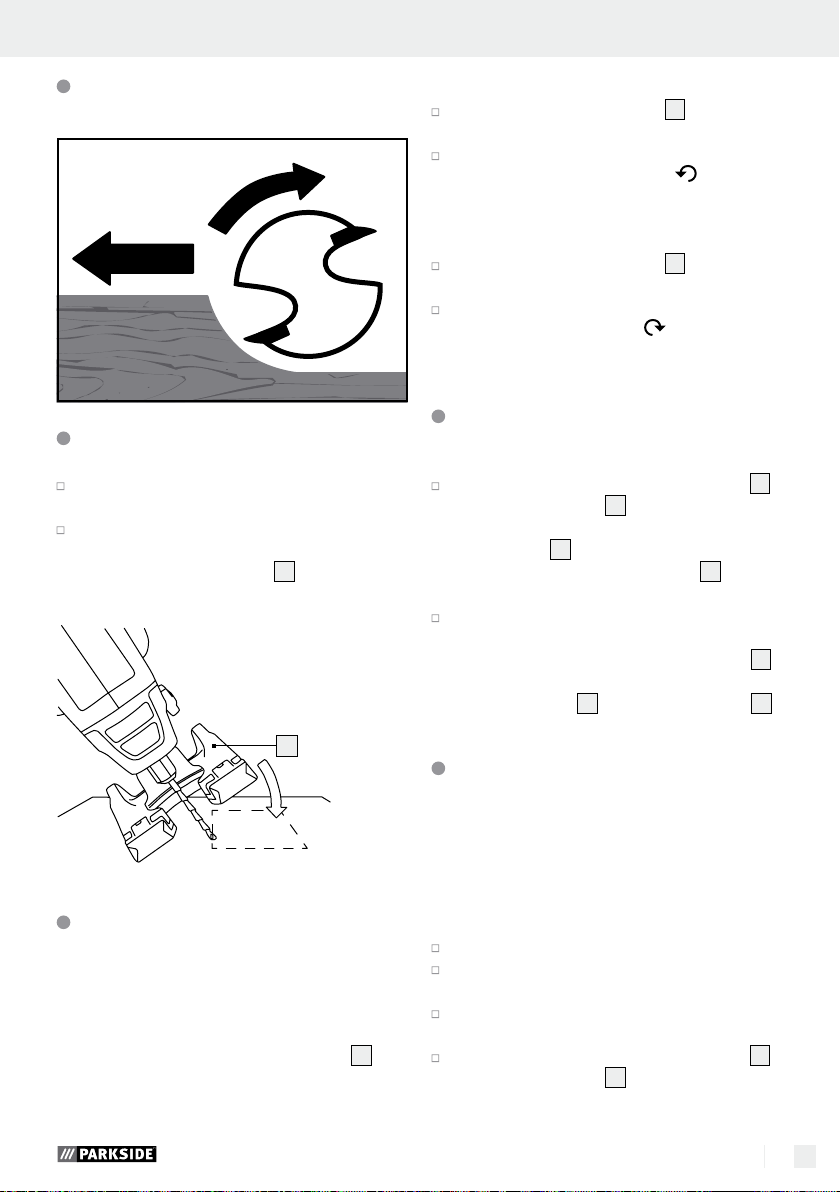
Changing tools (see Fig. C)
Note: Only use combination cutter accessory
parts with a shaft diameter of ø 4.8 mm.
Hold the spindle lock button 11 pressed down.
Loosen the clamping nut 10 with the wrench 14
by turning in an anticlockwise direction.
Change the tool.
Block the spindle lock, tighten the clamping
10
nut
using the open-ended spanner 14.
Bits:
The bits included are intended for the following
applications (see Fig. D).
Multi-purpose cutter (HSS)
Application: wood, particle board, plastic, aluminium and iron sheets
Slot cutter (HSS)
Application: wood, particle board, plastic
Sanding belts
Application: sanding wood
Note: Please use suitable accessories available
from your speciality retailer to cut wall tiles and /
or edit sheets of metal / light metal.
17
:
16
:
18
:
Installing sanding belts
Install the sanding belts 16 as shown in Figure C.
Switching ON / OFF (see Fig. A)
Switching on:
Press the ON / OFF switch 4.
Switching off:
Release the ON / OFF switch 4.
Setting the speed (see Fig. B)
Turn the speed controller 2 in a clockwise
direction to increase the speed.
Turn the speed controller 2 in an anticlockwise
direction to reduce the speed.
Setting the working depth
(see Fig. E)
Loosen the wing bolt 5.
Slide the base plate 7 to the desired working
depth (to cut through completely set approx.
3.2 mm deeper than the material thickness).
The recommended maximum cutting depth for
wood is 13 mm *(only applies to multipurpose
cutter (HSS)
Retighten the wing bolt 5.
18
).
9 GB/IE/CY

Operation
Milling direction for edges
Plunge cutting
Insert the bit into the work piece at an angle
of 45°.
Slowly straighten the bit to an angle of 90° to
begin the cut.
Note: The base plate
material surface.
7
must be flush with the
7
Pivot handle (see Fig. F)
Note: Turning the grip during the start up operations is forbidden. Remove the plug from the socket
and make sure that the swivel lock
Pivot to horizontal
Press and hold the bevel stop 13.
Turn the handle counter-clockwise from ver-
tical to horizontal until the bevel stop locks in.
13
is engaged.
Pivot to vertical
Press and hold the bevel stop 13.
Turn the handle clockwise from horizontal
to vertical until the bevel stop locks in.
Using the rip fence (see Fig. G)
Loosen the wing bolts 9 on the base plate 7
and slide the guide bar for the circle- / rip
15
fence
tom of the base plate
facing down.
Position the tool the desired distance from the
edge of the work piece. Tighten the wing bolts
to secure the circle- / ripe fence
plate
through the two openings in the bot-
7
, with the rip fence
15
to the foot
7
.
9
Cutting circles (see Fig. H)
Note: The position of the guide hole depends on the
desired result, either inside or outside of the edge
of the circle: inside for holes, outside for discs. The
radius can be set from ca. 5 to 16 cm.
Make a circle on the work piece.
Mark the centre and drill a hole into the hole
(plunge cut).
Drill a guide hole on the edge of the circle
(plunge cut) (guide hole diameter 3 mm).
Loosen the wing bolts 9 in the foot plate 7
and slide the guide rod for the circle- / rip
fence set
tom of the base plate
facing down.
Insert the centring tip in the middle of the circle.
Adjust the distance of the circle- / rip fence set 15
so as to plunge the bit into the guide hole at
the edge of the circle.
Lock the base plate 7 by tightening the wing
bolts
Press and hold the ON / OFF switch 4 to
power on the unit.
Slowly push the unit forward.
15
through the two holes in the bot-
7
, with the centring tip
9
.
10 GB/IE/CY

Dust extraction (see Fig. I)
Warranty
The tool features a dust extraction nozzle 6
to vacuum off dust.
Insert the adapter 19 in the extraction nozzle 6.
Connect a vacuum cleaner to the adapter 19.
Continuous tool operation
Locking the ON / OFF switch 4:
Activate the ON / OFF switch 4.
Press the locking switch 1 and release the
ON / OFF switch
Unlocking the ON / OFF switch
Activate the ON / OFF switch 4 and release.
4
.
4
:
Maintenance and Cleaning
The device requires no maintenance.
Clean the unit promptly after use.
Clean the device with a dry cloth, never use
petrol, solvents or cleaning agents harmful to
plastic.
Always keep the vents clear.
Remove dust clinging to the sander with a brush.
Service
Always have your
device repaired by qualified specialist
personnel using only original manu-
facturer parts. This will maintain the safety
of the device.
If the plug or mains
lead needs to be replaced, always
the work performed by the manufac-
turer or its service centre. This will maintain
the safety of the device.
have
The warranty for this appliance is for 3
years from the date of purchase. The appliance has been manufactured with care
and meticulously examined before delivery. Please retain your receipt as proof
of purchase. In the event of a warranty
claim, please make contact by telephone
with our Service Department. Only in this
way can a post-free despatch for your
goods be assured.
The warranty covers only claims for material and
maufacturing defects, but not for transport damage,
for wearing parts or for damage to fragile components, e.g. buttons or batteries. This product is for private use only and is not intended for commercial use.
The warranty is void in the case of abusive and improper handling, use of force and internal tampering
not carried out by our authorized service branch. Your
statutory rights are not restricted in any way by this
warranty.
The warranty period will not be extended by repairs
made unter warranty. This applies also to replaced
and repaired parts. Any damage and defects extant
on purchase must be reported immediately after
unpacking the appliance, at the latest, two days after
the purchase date. Repairs made after the expiration
of the warranty period are subject to payment.
GB
Service Great Britain
Tel.: 0871 5000 720
(0.10 GBP/Min.)
e-mail: kompernass@lidl.co.uk
IAN 102813
Note: Spare parts not listed (e.g. carbon brushes,
switches) can be ordered through our call centre.
11 GB/IE/CY
… / Disposal / Translation of the original declaration of conformity / Manufacturer
IE
Service Ireland
Tel: 1890 930 034
(0.08 EUR/Min. (peak)
0.06 EUR/Min. (off peak))
e-mail: kompernass@lidl.ie
IAN 102813
CY
Service Cyprus
Tel.: 8009 4409
e-mail: kompernass@lidl.com.cy
IAN 102813
Disposal
The packaging is made of environmentally
friendly materials, which may be disposed
through your local recycling facilities.
Do not dispose of electrical
power tools with household
rubbish!
In accordance with European Directive
on waste electrical and electronic equipment and
its implementation into national legislation, worn out
electrical power tools must be collected separately
and recycled in an environmentally friendly fashion.
Contact your local refuse disposal authority for more
details on the disposal of worn out electrical devices.
2012 / 19 / EU
Translation of the original
declaration of conformity /
Manufacturer
We, KOMPERNASS HANDELS GMBH, the person
responsible for documents: Mr Semi Uguzlu, BURGSTRASSE 21, 44867 BOCHUM, GERMANY, hereby
declare that this product complies with the following
standards, normative documents and EU directives:
Machinery Directive (2006 / 42 / EC)
EC Low Voltage Directive
(2006 / 95 / EC)
Electromagnetic Compatibility
(2004 / 108 / EC)
RoHS Directive
(2011 / 65 / EU)
harmonised standards applied:
EN 60745-1/A11:2010
EN 60745-2-4/A11:2011
EN 60745-2-17:2010, EN 62233:2008
EN 55014-1/A2:2011, EN 55014-2/A2:2008
EN 61000-3-2/A2:2009
EN 61000-3-3:2008
Type / Description of product:
Combination Cutter PSFS 250 A1
Date of manufacture: 08–2014
Serial number: IAN 102813
12 GB/IE/CY
Bochum, 31.08.2014
Semi Uguzlu
- Quality Manager -
We reserve the right to make technical modifications
in the interest of product advancement.

Eισαγωγή
Χρήση σύμφωνα με τους κανονισμούς ..........................................................................................Σελίδα 14
Εξοπλισμός ......................................................................................................................................Σελίδα 14
Περιεχόμενα συσκευασίας ..............................................................................................................Σελίδα 14
Τεχνικά στοιχεία ...............................................................................................................................Σελίδα 14
Γενικές υποδείξεις ασφάλειας για ηλεκτρικά εργαλεία
1. Θέση εργασίας-ασφάλεια ...........................................................................................................Σελίδα 15
2. Ηλεκτρική ασφάλεια ....................................................................................................................Σελίδα 15
3. Ασφάλεια ατόμων ........................................................................................................................Σελίδα 16
4. Ασφαλής λειτουργία και χρήση ηλεκτρονικών συσκευών.........................................................Σελίδα 16
5. Σέρβις ..........................................................................................................................................Σελίδα 17
Πρόσθετες υποδείξεις ασφάλειας για τον λειαντήρα
και το γυαλιστικό ..................................................................................................................Σελίδα 17
Πρόσθετες υποδείξεις ασφάλειας για εξωτερική φρέζα .........................Σελίδα 17
Λειτουργία ...................................................................................................................................Σελίδα 17
Ενεργοποίηση / απενεργοποίηση ...................................................................................................Σελίδα 18
Ρύθμιση στροφών.............................................................................................................................Σελίδα 18
Αλλαγή εργαλείου ............................................................................................................................Σελίδα 18
Εγκατάσταση ζωνών λείανσης ........................................................................................................Σελίδα 18
Ρύθμιση βάθους εργασίας ..............................................................................................................Σελίδα 18
Κατεύθυνση φρεζαρίσματος σε γωνίες ..........................................................................................Σελίδα 19
Εκτέλεση τομής βύθισης ..................................................................................................................Σελίδα 19
Αιώρηση χειρολαβής .......................................................................................................................Σελίδα 19
Χρήση παράλληλου οδηγού ...........................................................................................................Σελίδα 19
Πριόνισμα κύκλου ...........................................................................................................................Σελίδα 19
Απορρόφηση σκόνης .....................................................................................................................Σελίδα 20
Χρήση εργαλείου σε συνεχή λειτουργία .........................................................................................Σελίδα 20
Συντήρηση και καθαρισμός .........................................................................................Σελίδα 20
Σέρβις ..............................................................................................................................................Σελίδα 20
Εγγύηση ........................................................................................................................................Σελίδα 20
Απόσυρση ...................................................................................................................................Σελίδα 21
Μετάφραση της πρωτότυπης δήλωσης συμμόρφωσης /
Κατασκευαστή ..........................................................................................................................Σελίδα 22
13 GR/CY

Eισαγωγή
Φρεζα-kombi PSFS 250 A1
Q
Eισαγωγή
Σας συγχαίρουμε για την αγορά της νέας σας
συσκευής. Επιλέξατε ένα προϊόν υψηλών προδιαγραφών. Οι οδηγίες χρήσης είναι μέρος αυτού
του προϊόντος. Περιέχουν σημαντικές πληροφορίες
σχετικά με την ασφάλεια, το χειρισμό και την απόρριψη.
Πριν τη χρήση του προϊόντος εξοικειωθείτε με όλες
τις οδηγίες χρήσης και ασφαλείας. Χρησιμοποιείτε
το προϊόν μόνο με τον τρόπο που περιγράφεται
και για τον τομέα εφαρμογής που αναφέρεται. Σε
περίπτωση μεταβίβασης του προϊόντος σε τρίτους
παραδώστε μαζί και όλα τα έγγραφα.
Χρήση σύμφωνα με τους
κανονισμούς
Αυτή η συσκευή – με το συνιστόμενο εργαλείο και
εξάρτημα - είναι σχεδιασμένο για επεξεργασία υλικών όπως ξύλο, πλαστικό, ινοσανίδες, πλακάκια
τοίχου, λαμαρίνες αλουμινίου και σιδήρου. Ενδείκνυται επίσης για λείανση με διαφορετικά κυκλικά
τριβεία καθώς και για φρεζάρισμα με εξαρτήματα
φρέζας με διάμετρο άτρακτου 4,8 mm. Οποιαδήποτε άλλη χρήση ή τροποποίηση της συσκευής θεωρείται ως αντικανονική και εγκυμονεί σοβαρούς
κινδύνους ατυχημάτων. Ο κατασκευαστής δεν αναλαμβάνει καμία ευθύνη για φθορές που οφείλονται
σε αντικανονική χρήση. Δεν προορίζεται για επαγγελματική χρήση.
10
Περικόχλιο συγκράτησης
11
Πλήκτρο παύσης ατράκτου
12
Σχισμή αερισμού
13
Αιωρούμενο κλείδωμα
14
Κλειδί διπλού ανοίγματος
15
Κυκλικό / παράλληλο εξάρτημα κοπής
16
Ζώνες λείανσης
17
Φρέζα υποδοχής (HSS)
18
Φρέζα πολλαπλής χρήσης (HSS)
19
Προσαρμογέας (στόμιο αναρρόφησης)
Περιεχόμενα συσκευασίας
1 Φρέζα πολλαπλών λειτουργιών PSFS 250 A1
1 Παράλληλο σημείο αναστολής με λειτουργία
κυκλικής κοπής
1 Προσαρμογέας ηλεκτρικής σκούπας
1 Διπλό κλειδί
1 Φρέζα πολλαπλής χρήσης (HSS)
1 Φρέζα υποδοχής (HSS)
1 Άξονας σύσφιξης λείανσης
6 Ζώνες λείανσης
1 Οδηγίες χρήσης
Τεχνικά στοιχεία
Ονομαστική ισχύς: 250 W
Τάση : 230 V∼, 50 Hz
Αριθμός στροφών
ρελαντί (n
Υποδοχή εργαλείου για: 4,8mm
Κλάση προστασίας: II /
): 10.000–28.000 / min
0
-1
Εξοπλισμός
1
Διακόπτης παύσης
2
αδιαβάθμητος ρυθμιστής στροφών
3
Καλώδιο ηλεκτρικού δικτύου
4
Διακόπτης ΕΝΤΟΣ / ΕΚΤΟΣ
5
Βίδα ρύθμισης με πτερύγια
6
Στόμιο αναρρόφησης
7
Πλάκα έδρασης
8
Λαβίδα σύσφιξης
9
Βίδα ρύθμισης με πτερύγια (πλάκα έδρασης)
14 GR/CY
Πληροφορίες θορύβου και δονήσεων:
Υπολογισμένη τιμή για θόρυβο εξακριβώνεται σύμφωνα με EN 60745. Η στάθμη ηχητικής πίεσης
που έχει αξιολογηθεί με A ηλεκτρικής συσκευής
ανέρχεται σε:
Στάθμη ηχητικής πίεσης: 75 dB(A)
Στάθμη ηχητικής ισχύος: 86 dB(A)
Ανασφάλεια K: 3 dB(A)
Φοράτε ωτοασπίδες!

Eισαγωγή / Γενικές υποδείξεις ασφάλειας για ηλεκτρικά εργαλεία
Υπολογισμένη επιτάχυνση, τυπικά:
Δονήσεις σε χέρι / βραχίονα a
Ανασφάλεια K = 1,5 m / s
2
< 2,5 m / s
h
2
Η αναφερόμενη στις
παρούσες οδηγίες στάθμη δονήσεων μετρήθηκε με
τυποποιημένη μέθοδο μέτρησης σύμφωνα με το
πρότυπο EN 60745 και μπορεί να χρησιμοποιηθεί
για τη σύγκριση της συσκευής. Η δεδομένη τιμή
εκπομπής δονήσεων μπορεί επίσης να χρησιμοποιηθε
σε μια εισαγωγική εκτίμηση της έκθεσης.
Η στάθμη δονήσεων μεταβάλλεται ανάλογα με τη
χρήση του ηλεκτρικού εργαλείου και σε μερικές
περιπτώσεις ενδέχεται να υπερβαίνει την τιμή που
αναφέρεται στις παρούσες οδηγίες. Η επιβάρυνση
δονήσεων ενδέχεται να υποτιμηθεί, σε περίπτωση
που το ηλεκτρικό εργαλείο χρησιμοποιείται τακτικά
με τέτοιο τρόπο.
Υπόδειξη: Για τον ακριβή υπολογισμό της επιβάρυνσης κραδασμών κατά τη διάρκεια ενός ορισμένου χρονικού διαστήματος εργασίας θα πρέπει να
ληφθούν υπόψη και οι χρόνοι κατά τους οποίους
η συσκευή είναι απενεργοποιημένη ή λειτουργεί χωρίς όμως να παράγει πραγματικά έργο. Αυτό μπορεί
να μειώσει σημαντικά την επιβάρυνση κραδασμών
για το συνολικό χρονικό διάστημα εργασίας.
Q
Γενικές υποδείξεις ασφάλειας
για ηλεκτρικά εργαλεία
Διαβάστε
όλες τις υποδείξεις ασφάλειας και
οδηγίες! Οι παραβιάσεις κατά την
τήρηση των υποδείξεων ασφάλειας και των οδηγιών
ενδέχεται να προκαλέσουν ηλεκτροπληξία, πυρκαγιά
ή / και σοβαρούς τραυματισμούς.
Διαφυλαξτε ολες τις υποδειξεις ασφαλειας
και τις οδηγιες για μελλοντικη χρηση!
Ο ορος που χρησιμοποιειται στις υποδειξεις
ασφαλειας «ηλεκτρονικο εργαλειο» αναφερεται σε
ηλεκτρικα εργαλεια που λειτουργουν με το δικτυο
(με καλωδιο δικτυου) και σε αυτa που λειτουργουν
με μπαταρια (χωρις καλωδιο δικτυου).
1. Θέση εργασίας-ασφάλεια
α) Διατηρείτε το χώρο εργασίας σας
καθαρό και καλά φωτισμένο. Η
ακαταστασία καθώς και ο ελλιπής φωτισμός
του χώρου εργασίας μπορεί να οδηγήσει σε
ατυχήματα.
β) Μην εργάζεστε με τη συσκευή σε
περιβάλλον όπου υφίσταται κίνδυνος
έκρηξης, στο οποίο υπάρχουν εύφλεκτα
ί
υγρά, αέρια ή σκόνη. Τα ηλεκτρονικά
εργαλεία παράγουν σπίθες, οι οποίες μπορεί
να αναφλέξουν τη σκόνη ή τους ατμούς.
γ) Κρατήστε τα παιδιά και άλλα άτομα
μακριά από το ηλεκτρονικό εργαλείο
κατά τη διάρκεια
χρήσης του. Σε περίπτωση
μη τήρησης ίσως χάσετε τον έλεγχο της συσκευής.
2. Ηλεκτρική ασφάλεια
α) Το βύσμα σύνδεσης συσκευής θα πρέπει
να ταιριάζει στην πρίζα. Απαγορεύεται
η τροποποίηση με οποιοδήποτε τρόπο
του βύσματος. Απαγορεύεται η χρήση
βύσματος προσαρμογέα μαζί με συσκευέ
με προστατευτική γείωση. Το ανέπαφο
βύσμα και η κατάλληλη πρίζα μειώνουν τον
κίνδυνο πρόκλησης ηλεκτροπληξίας.
β) Αποφύγετε τη σωματική επαφή με
γειωμένες επιφάνειες, όπως σωλήνες,
θερμαντικά σώματα, εστίες και ψυγεία.
Υφίσταται υψηλός κίνδυνος ηλεκτροπληξίας
όταν το σώμα σας γειωθεί.
γ) Κρατήστε τη συσκευή μακριά από τη
βροχή και την υγρασία. Η εισχώρηση
νερού μέσα σε μία ηλεκτρονική συσκευή αυξάνει
τον κίνδυνο ηλεκτροπληξίας.
δ) Μην χρησιμοποιείτε το καλώδιο για
άλλο λόγο, για να μεταφέ ρετε τη
συσκευή, για να την αναρτήσετε ή για
να τραβήξετε το βύσμα από την πρίζα.
Κρατήστε το καλώδιο μακριά από
θερμότητα, λάδι, αιχμηρές ακμές ή
κινούμενα εξαρτήματα συσκευής.
Κατεστραμμένο ή τυλιγμένο καλώδιο αυξάνει
τον κίνδυνο πρόκλησης ηλεκτροπληξίας.
ς
15 GR/CY

Γενικές υποδείξεις ασφάλειας για ηλεκτρικά εργαλεία
ε) Για χρήση ηλεκτρονικής συσκευής σε
εξωτερικούς χώρους, χρησιμοποιήστε
μόνο καλώδιο επέκτασης που είναι
κατάλληλο για εξωτερική χρήση. Η
χρήση ενός καλωδίου κατάλληλο για εξωτερική
χρήση μειώνει τον κίνδυνο ηλεκτροπληξίας.
ζ) Σε περίπτωση που είναι αναπόφευκτη
η λειτουργία του ηλεκτρικού εργαλείου
σε υγρό περιβάλλον, χρησιμοποιείτε
προστατευτικό διακόπτη συνολικού
ρεύματος προς το σφάλμα. Η χρήση
προστατευτικού διακόπτη συνολικού ρεύματος
προς το σφάλμα μειώνει τον κίνδυνο
ηλεκτροπληξίας.
3. Ασφάλεια ατόμων
α) Επ
ιδείξτε μεγάλη προσοχή, έχετε πάντοτε
επίγνωση των πράξεών σας και δείξτε
ιδιαίτερη συναίνεση στην εργασία που
πραγματοποιείτε με το ηλεκτρονικό
εργαλείο. Μην χρησιμοποιείτε τη συσκευή
όταν δεν
όταν
υπό
ή φαρμάκων. Ακόμα και μόλις μία στιγμή
αφηρημάδας κατά τη χρήση της συσκευής
μπορεί να οδηγήσει σε σοβαρούς τραυματισμούς.
β) Φοράτε προσωπικό προστατευτικό εξο-
πλισμό και πάντα προστατευτικά γυαλιά. Ο προσωπικός προστατευτικός εξοπλισμός
όπως είναι αναπνευστική μάσκα, προστατευτικά
παπούτσια που δεν γλιστράνε, προστατευτικό
κράνος ή ωτοασπίδες, ανάλογα με το είδος και
την εφαρμογή του μειώνουν τον κίνδυνο πρόκλησης τραυματισμών.
γ) Αποφεύγετε την αθέλητη θέση σε
λειτουργία. Βεβαιωθείτε ότι το ηλεκτρικό εργαλείο είναι απενεργοποιημένο
προτού το συνδέσετε στην ηλεκτρική
τροφοδοσία ή το πάρετε και το μεταφέρετε. Εάν κατά τη μεταφορά της συσκευής
έχετε το δάκτυλό σας στο διακόπτη ΕΝΤΟΣ /
ΕΚΤΟΣ ή η συσκευή είναι ενεργοποιημένη,
ενδέχεται να προκληθούν ατυχήματα.
δ) Απομακρύνετε τα εργαλεία ρύθμισης ή
τα κλειδιά προτού ενεργοποιήσετε τη
16 GR/CY
είσαστε συγκεντρωμένοι ή
νοιώθετε κούραση ή ενώ βρίσκεστε
την επήρεια ναρκωτικών, αλκοόλ
συσκευή. Ενα εργαλείο ή ένα κλειδί που
βρίσκεται πάνω σε ένα περιστρεφόμενο εξάρτημα
συσκευής μπορεί να προκαλέσει τραυματισμούς.
ε) Αποφεύγετε αντικανονική στάση του
σώματός σας. Φροντίζετε ώστε να υπάρχει
πάντα σταθερή θέση και διατηρείτε
ανά πάση στιγμή την ισορροπία σας.
Ετσι μπορείτε να ελέγχετε καλύτερα τη συσκευή
και ιδιαίτερα σε απρόσμενες καταστάσεις.
ζ) Φοράτε κατάλληλο ρουχισμό. Μην
φοράτε φαρδιά ρούχα και κοσμήματα.
Κρατήστε τα μαλλιά, το ρουχισμό και
τα γάντια μακριά από τα κινούμενα
εξαρτήματα. Ο φαρδύς ρουχισμός που δεν
έχει στενή εφαρμογή, τα κοσμήματα ή τα μαλλιά
μπορεί να πιαστούν από τα κινούμενα εξαρτήματα.
η) Κατά τη συναρμολόγηση διατάξεων
αναρρόφησης και συλλογής, φροντί
στε ώστε αυτές να έχουν συνδεθεί και
να χρησιμοποιούνται σωστά. Η χρήση
τέτοιου είδους διατάξεων μειώνει τον κίνδυνο
από τη σκόνη.
4.
Ασφαλής λειτουργία και χρήση
ηλεκτρονικών συσκευών
α) Μην υπερφορτώνετε τη συσκευή.
Χρησιμοποιήστε το ηλεκτρονικό
εργαλείο που είναι κατάλληλο για την
εργασία σας. Με το κατάλληλο ηλεκτρονικό
εργαλείο μπορείτε να εργαστείτε καλύτερα και με
μεγαλύτερη ασφάλεια εντός του καθορισμένου
τομέα απόδοσης.
β) Μην χρησιμοποιείτε ηλεκτρονικό
εργαλείο, του οποίου ο διακόπτης
είναι ελαττωματικός. Ενα ηλεκτρονικό
εργαλείο που δεν μπορεί να ενεργοποιηθεί ή να
απενεργοποιηθεί είναι επικίνδυνο και θα πρέπει
να επιδιορθωθεί.
γ)
Πριν προβείτε σε ρυθμίσεις της μηχανής
σε αντικατάσταση εξαρτημάτων ή σε
απόθεση της μηχανής, αποσυνδέετε το
βύσμα από την ηλεκτρική πρίζα. Αυτά
τα προστατευτικά μέτρα μειώνουν τον κίνδυνο
αθέμιτης εκκίνησης της συσκευής.
δ) Φυλάξτε τα ηλεκτρονικά εργαλεία που
δεν χρησιμοποιείτε μακριά από παιδιά.
,

... / Πρόσθετες υποδείξεις ασφάλειας... / Πρόσθετες υποδείξεις ... / Λειτουργία
Μην επιτρέπετε τη χρήση της συσκευής
σε άτομα, τα οποία δεν είναι έμπιστα ή
τα οποία δεν έχουν διαβάσει τις οδηγίες.
Τα ηλεκτρονικά εργαλεία είναι επικίνδυνα όταν
χρησιμοποιούνται από άπειρα άτομα.
ε) Φροντίστε τη συσκευή με προσοχή.
Ελέγχετε αν τα κινούμενα εξαρτήματα
λειτουργούν άψογα και δεν μπλοκάρουν, αν υπάρχουν σπασμένα ή
κατεστραμμένα εξαρτήματα έτσι ώστε
να επηρεάζεται αρνητικά η λειτουργία
της συσκευής. Αναθέστε την επιδιό ρθωση
των ελαττωματικών εξαρτη μάτων πριν
από τη χρήση στης συσ κευής. Πολλά
ατυχήματα οφείλονται σε ηλεκτρονικές συσκευές
που δεν έχουν συντηρηθεί σωστά.
ζ) Διατηρήστε τα εργαλεία κοπής αιχμηρά
και καθαρά. Τα προσεγμένα εργαλεία κοπής
μπλοκάρουν λιγότερο και κόβουν πιο εύκολα.
η) Χρησιμοποιήστε το ηλεκτρονικό εργα-
λείο, το εξάρτημα, τα εργαλεία εφαρμογής κ.τ.λ. σύμφωνα με τις οδηγίες
τους και με τον τρόπο που περιγράφεται για αυτό τον ειδικό τύπο συσκευής.
Λάβετε υπόψη σας τις συνθήκες εργασίας και τις δραστηριότητες που πρέπει
να πραγματοποιηθούν. Η χρήση ηλεκτρο-
νικών εργαλείων για εφαρμογή άλλη από αυτή
που προδιαγράφεται μπορεί να οδηγήσει σε
επικίνδυνες καταστάσεις.
5. Σέρβις
α) Αναθέστε την επιδιόρθωση της συσκευ-
ής σας σε υπηρεσία εξυπηρέτησης πε
τών ή σε εξειδικευμένο ηλεκτρολόγο
και χρησιμοποιήστε μόνο αυθεντικά
ανταλλακτικά. Με τον τρόπο αυτό μπορεί
να διασφαλιστεί το γεγονός ότι διατηρείται το
επίπεδο ασφάλειας της συσκευής.
λα-
Πρόσθετες υποδείξεις ασφά-
λειας για τον λειαντήρα και το
γυαλιστικό
ΤΟΞΙΚΕΣ ΣΚΟΝΕΣ! Η επεξεργασία επικίν-
δυνων / τοξικών σκονών εγκυμονεί κίνδυνο για
την υγεία για τους χειριστές ή για τα άτομα
που βρίσκονται πλησίον.
Αποφύγετε τη λείανση σε χρώματα που περιέχουν
μόλυβδο ή άλλα υλικά που βλάπτουν την υγεία.
Απαγορεύεται η επεξεργασία υλικών που περι-
έχουν αμίαντο. Ο αμίαντος ισχύει ως καρκινογόνο.
Φοράτε γυαλιά προστασίας και μια κατάλληλη
μάσκα προστασίαςι από τη σκόνη!
Πρόσθετες υποδείξεις ασφάλειας
για εξωτερική φρέζα
Κρατήστε το εργαλείο μόνο από μονω-
μένες επιφάνειες λαβών, επειδή η φρέζα
μπορεί να πετύχει το ίδιο το καλώδιο
ρεύματος της. Η επαφή με έναν αγωγό που
φέρει τάση μπορεί να θέσει υπό τάση τα μεταλλικά εξαρτήματα της συσκευής και να οδηγήσει
σε ηλεκτροπληξία.
Χρησιμοποιήστε μόνο φρέζες της σωστής
διαμέτρου άξονα, οι οποίες είναι κατάλληλες
για τις στροφές του ηλεκτρικού εργαλείου.
Στερεώστε και ασφαλίστε το τεμάχιο
εργασίας μέσω πίεσης ή κατά αλλο
τρόπο σε ένα σταθερό υπόστρωμα
κρατάτε το τεμάχιο εργασίας μόνο με το χέρι ή
ενάντια στο σώμα, παραμένει ασταθές, κάτι που
μπορεί να οδηγήσει σε απώλεια ελέγχου.
Λειτουργία
Ποτέ μην χρησιμοποιείτε την συσκευή για άλλο
σκοπό και μόνο με γνήσια μέρη/εξαρτήματα. Η
χρήση άλλων εργαλείων εκτός των προτεινόμενων
στις οδηγίες χρήσης μερών ή άλλων εξαρτημάτων
ενδέχεται να αποτελέσει κίνδυνο τραυματισμού για
σας. Χρησιμοποιείτε μόνο πλήρως ξεδιπλωμένα και
χωρίς φθορές καλώδια προέκτασης με χωρητικότητα
τουλάχιστον 5 A.
. Αν
17 GR/CY

Λειτουργία
ΠΡΟΣΟΧΗ: Μην χρησιμοποιείτε αυτό το εργαλείο για τη δημιουργία διατρήσεων στο περιβάλλον
εγκαταστάσεων ή οπών με ηλεκτροφόρα καλώδια
που φέρουν τάση ή σε τοίχους, πίσω από τους
οποίους είναι πιθανώς καλυμμένα ηλεκτροφόρα
καλώδια που φέρουν τάση. Το εξάρτημα θα μπορούσε να μεταφέρει ρεύμα στο εργαλείο, κάτι που
για τον χρήστη είναι συνδεμένο με τον κίνδυνο
ηλεκτροπληξίας.
Χαλαρώστε τον μηχανισμό ασφάλισης ή αφαι-
ρέστε την ασφάλεια, για να θέσετε το σχετικό
κύκλωμα ρεύματος χωρίς τάση.
Προσοχή: Κρατήστε το εργαλείο πάντα από το
πλαστικό περίβλημα και φοράτε κατά την εργασία
με το εργαλείο πάντα γυαλιά προστασίας.
Ενεργοποίηση / απενεργοποίηση
(βλέπε Εικ. A)
Ενεργοποίηση:
Πατήστε το διακόπτη ΕΝΤΟΣ / ΕΚΤΟΣ 4.
Απενεργοποίηση:
Αφήστε ελεύθερο το διακόπτη ΕΝΤΟΣ /
ΕΚΤΟΣ
4
.
Χαλαρώστε το περικόχλιο στήριξης 10 με το
κλειδί διπλού ανοίγματος
το αριστερόστροφα.
Αλλάξτε το εργαλείο.
Μπλοκάρετε την παύση άξονα, σφίξτε το περι-
κόχλιο στήριξης
διπλού ανοίγματος
Εξαρτήματα:
Τα εσωκλειόμενα εξαρτήματα καλύπτουν τους
ακόλουθους τομείς εφαρμογής (βλέπε Εικ. D).
Φρέζα πολλαπλής χρήσης (HSS)
Καταλληλότητα: Ξύλο, νοβοπάν, πλαστικό, λαμαρίνες αλουμινίου και σιδήρου
Φρέζα υποδοχής (HSS)
Καταλληλότητα: Ξύλο, νοβοπάν, πλαστικό
Ζώνες λείανσης
Καταλληλότητα: Λείανση ξύλου
Υπόδειξη: Για να κόψετε πλακάκια τοίχου και/ή
κατεργασία λαμάρινών/ελαφρών μετάλλων χρησιμοποιείτε παρακαλούμε το αντίστοιχο εξάρτημα
από θήκη εργαλείων.
10
16
14
περιστρέφοντας
με την βοήθεια του κλειδιού
14
.
18
:
17
:
:
Εγκατάσταση ζωνών λείανσης
Ρύθμιση στροφών (βλέπε Εικ. B)
Στρέψτε τον διακόπτη ρύθμισης στροφών 2
προς τα δεξιά, για να αυξήσετε τον αριθμό
στροφών.
Στρέψτε τον διακόπτη ρύθμισης στροφών 2
προς τα αριστερά, για να μειώσετε τον αριθμό
στροφών.
Αλλαγή εργαλείου (βλέπε Εικ. C)
Υπόδειξη: Χρησιμοποιείτε μόνο εξαρτήματα
φρέζας πολλαπλών λειτουργιών με μια διάμετρο
άξονα ø 4,8 mm.
Κρατήστε πατημένο το πλήκτρο παύσης
ατράκτου
18 GR/CY
11
.
Εγκαταστήστε τις ζώνες λείανσης 16 όπως
εμφανίζεται στην εικόνα C.
Ρύθμιση βάθους εργασίας
(βλέπε Εικ. E)
Χαλαρώστε την βίδα ρύθμισης με πτερύγια 5.
Σύρετε την πλάκα έδρασης 7 στο επιθυμητό βά-
θος εργασίας
πάνω από το πάχος υλικού).
Το μέγιστο συνιστώμενο βάθος τομής για ξύλο
κυμαίνεται στα 13 mm *(ισχύει μόνο για φρέ-
ζες πολλαπλής χρήσης (HSS)
Σφίξτε πάλι την βίδα ρύθμισης με πτερύγια 5.
(για πλήρη τομή περίπου 3,2 mm
18
).
Λειτουργία
Κατεύθυνση φρεζαρίσματος
σε γωνίες
Εκτέλεση τομής βύθισης
Εισάγετε το εξάρτημα σε γωνία 45° στο
τεμάχιο εργασίας.
Ευθυγραμμίστε το εξάρτημα αργά σε γωνία
90°, για να ξεκινήσετε την τομή.
Υπόδειξη: Η πλάκα έδρασης
βρίσκεται συνδεμένη στην επιφάνεια υλικού.
7
πρέπει να
Αιώρηση σε οριζόντια θέση
Πιέστε το κλείδωμα αιώρησης 13 και κρατήστε
το πατημένο.
Στρέψτε την χειρολαβή αριστερόστροφα από
την κάθετη στην οριζόντια θέση
ώσπου να κλειδώσει στο κλείδωμα αιώρησης.
Αιώρηση σε κάθετη θέση
Πιέστε το κλείδωμα αιώρησης 13 και κρατήστε
το πατημένο.
Στρέψτε την χειρολαβή δεξιόστροφα από την
οριζόντια στην κάθετη θέση
να κλειδώσει στο κλείδωμα αιώρησης.
για τόσο,
για τόσο, ώσπου
Χρήση παράλληλου οδηγού
(βλέπε Εικ. G)
Χαλαρώστε τις βίδες ρύθμισης με πτερύγια 9
της πλάκας έδρασης
οδήγησης του εξαρτήματος κυκλικής / παράλ-
ληλης τομής
κάτω πλευρά της πλάκας έδρασης
παράλληλος οδηγός να δείχνει προς τα κάτω.
Ευθυγραμμίστε το εργαλείο στην επιθυμητή
απόσταση για γωνίες τεμαχίου εργασίας.
Εφαρμώστε τις βίδες ρύθμισης με πτερύγιο
για να στερεώσετε το πρόσθετο κυκλικής/πα-
ράλληλης κοπής
7
και σύρετε την ράγα
15
μέσω των δυο εγκοπών στην
7
15
στην πλάκα έδρασης 7.
, ώστε ο
9
,
7
Αιώρηση χειρολαβής
(βλέπε Εικ. F)
Υπόδειξη: Δεν επιτρέπεται να στρέφετε την χειρο-
λαβή κατά την διάρκεια της θέσης σε λειτουργία.
Τραβήξτε τον ρευματολήπτη από την πρίζα και
εξασφαλίστε ότι το περιστροφικό κλείστρο
κλειδωμένο.
13
είναι
Πριόνισμα κύκλου (βλέπε Εικ. H)
Υπόδειξη: Η οπή οδηγού τοποθετείται ανεξάρτη-
τα από το επιθυμητό απότέλεσμα εντός ή εκτός
από το άκρο κύκλου: Εντός για μια οπή - εκτός
για ένα φύλλο. Η ακτίνα μπορεί να σταθεροποιηθεί
από περ. 5 ως 16 cm.
Τραβήξτε έναν κύκλο από το τεμάχιο εργασίας.
Σημειώστε την μέση κύκλου και τρυπήστε μια οπή
σε αυτόν (βάθος τομής).
Τρυπήστε μια οπή οδηγού στο άκρο κύκλου
(Τομή βύθισης) (διάμετρος οπής οδηγού 3 mm).
Χαλαρώστε τις βίδες ρύθμισης με πτερύγια 9
της πλάκας έδρασης
οδήγησης του εξαρτήματος κυκλικής / παράλ-
7
και σύρετε την ράγα
19 GR/CY

Λειτουργία / Συντήρηση και καθαρισμός / Σέρβις / Εγγύηση
ληλης τομής 15 μέσω των δυο εγκοπών στην
κάτω πλευρά της πλάκας έδρασης
μύτη κεντραρίσματος να δείχνει προς τα κάτω.
Εισάγετε την μύτη κεντραρίσματος στην μέση
κύκλου.
Ευθυγραμμίστε την απόσταση του εξαρτήματος
κυκλικής / παράλληλης κοπής
εξάρτημα να βυθιστεί στην οπή οδηγού στο
άκρο κύκλου.
Σταματήστε την πλάκα έδρασης 7 μέσω σφιξί-
ματος των βιδών με πτερύγια
Ενεργοποιήστε τη συσκευή με το να πιέσετε και
να κρατήσετε τον διακόπτη ON / OFF
Σύρετε το εργαλείο αργά προς τα εμπρός.
7
15
έτσι, ώστε το
9
.
, ώστε η
4
Απορρόφηση σκόνης
(βλέπε Εικ. I)
Το εργαλείο είναι εξοπλισμένο με ένα στόμιο
απορρόφησης
Εισάγετε τον προσαρμογέα 19 στο στόμιο
αναρρόφησης
Συνδέστε μια ηλεκτρική σκούπα στον
προσαρμογέα
6
για την απορρόφηση σκόνης.
6
.
19
.
Χρήση εργαλείου σε συνεχή
λειτουργία
Παύση διακόπτη ΕΝΤΟΣ/ΕΚΤΟΣ 4:
Αγγίξτε το διακόπτη ΕΝΤΟΣ / ΕΚΤΟΣ 4.
Πιέστε τώρα το διακόπτη παύσης 1 και ελευ-
θερώστε τον διακόπτη ΕΝΤΟΣ / ΕΚΤΟΣ
Ανύψωση της παύσης του διακόπτη
EΝΤΟΣ /ΕΚΤΟΣ
Αγγίξτε το διακόπτη ΕΝΤΟΣ / ΕΚΤΟΣ 4 και
αφήστε τον ελεύθερο.
4
:
Συντήρηση και καθαρισμός
Η συσκευή δεν απαιτεί συντήρηση.
Καθαρίζετε τη συσκευή αμέσως μετά το πέρας
της εργασίας.
Για τον καθαρισμό της συσκευής χρησιμοποιή-
στε ένα στεγνό πανί και σε καμία περίπτωση
20 GR/CY
βενζίνη, διαλυτικά ή καθαριστικά μέσα, τα
οποία βλάπτουν πλαστικό.
Διατηρείτε πάντα καθαρές τις οπές αερισμού.
Απομακρύνετε τη σκόνη λείανσης που επικολ-
λάται με ένα πινέλο.
Σέρβις
Αναθέστε την
επιδιόρθωση της συσκευής σας στην
υπηρεσία service ή σε εξειδικευμένο
.
4
.
ηλεκτρολόγο και χρησιμοποιήστε μόνο
αυθεντικά ανταλλακτικά. Με τον τρόπο
αυτό μπορεί να διασφαλιστεί το γεγονός ότι δι-
ατηρείται το επίπεδο ασφάλειας της συσκευής.
Αναθέτετε πά-
ντα την αντικατάσταση του βύσματος
ή του καλωδίου δικτύου στον κατα-
σκευαστή της συσκευής ή στην υπηρε-
σία εξυπηρέτησης πελατών. Με τον τρόπο
αυτό μπορεί να διασφαλιστεί το γεγονός ότι δι-
ατηρείται το επίπεδο ασφάλειας της συσκευής.
Υπόδειξη: Μπορείτε να παραγγείλετε μη-παρουσιάζομενα ανταλλακτικά (όπως π.χ. καρβουνάκια, διακόπτες) από το τηλεφωνικό μας κέντρο.
Q
Εγγύηση
Έχετε για αυτή τη συσκευή 3 χρόνια
εγγύηση από την ημερομηνία αγοράς. Η
συσκευή κατασκευάστηκε και ελέγχθηκε
προσεκτικά πριν από την αποστολή. Παρακαλούμε φυλάξτε την απόδειξη ταμείου
ως απόδειξη για την αγορά. Παρακαλούμε
επικοινωνήστε τηλεφωνικά με την υπηρεσία
σέρβις σε περίπτωση εγγύησης. Μόνο έτσι
μπορεί να εξασφαλιστεί μια δωρεάν αποστολή του εμπορεύματός σας.
Η απόδοση εγγύησης ισχύει μόνο για σφάλματα
υλικού ή κατασκευής, όχι όμως για ζημιές από τη
μεταφορά, για εξαρτήματα φθοράς ή για βλάβες
σε εύθραυστα εξαρτήματα, π.χ. διακόπτες ή συσσωρευτές. Το προϊόν προορίζεται μόνο για την
ιδιωτική και όχι για την επαγγελματική χρήση.

Εγγύηση / Απόσυρση
Σε περίπτωση κακής μεταχείρισης και ακατάλληλης
χρήσης, σε χρήση βίας και σε παρεμβάσεις οι οποίες δεν διεξήχθησαν από το εξουσιοδοτημένο μας
τμήμα σέρβις, η εγγύηση παύει να ισχύει. Τα νομικά
σας δικαιώματα δεν περιορίζονται μέσω αυτής της
εγγύησης.
Ο χρόνος εγγύησης δεν επεκτείνεται μέσω της απόδοσης εγγύησης. Αυτό ισχύει και για εξαρτήματα
τα οποία έχουν αντικατασταθεί ή επισκευαστεί.
Ενδεχόμενες ήδη υπάρχουσες κατά την αγορά,
ζημιές και ελλείψεις πρέπει να αναφέρονται αμέσως
μετά την αποσυσκευασία, το αργότερο όμως δύο
ημέρες μετά την ημερομηνία αγοράς. Επισκευές που
εμφανίζονται μετά τη λήξη του χρόνου εγγύησης
χρεώνονται.
GR
Σέρβις Ελλάδα
Tel.: 801 5000 019
(0,03 EUR/Min.)
e-mail: kompernass@lidl.gr
IAN 102813
CY
Σέρβις Κύπρος
Tel.: 8009 4409
e-mail: kompernass@lidl.com.cy
κό δίκαιο θα πρέπει οι χρησιμοποιημένες ηλεκτρονικές συσκευές να συλλέγονται σε ξεχωριστό χώρο
και να ανακυκλώνονται οικολογικά.
Δυνατότητες απόσυρσης των χρησιμοποιημένων
συσκευών θα πληροφορηθείτε από τη διαχείριση
κοινότητας ή πόλης σας.
IAN 102813
Q
Απόσυρση
Η συσκευασία αποτελείται από υλικά
φιλικά προς το περιβάλλον που μπορείτε
να τα πετάξετε στους τοπικούς χώρους
ανακύκλωσης.
Απαγορεύεται η απόσυρση
ηλεκτρονικών εργαλείων μαζί
με τα οικιακά απορρίμματα!
Σύμφωνα με την Ευρωπαϊκή Οδηγία
σχετικά με τις ηλεκτρονικές συσκευές και τις παλιές
ηλεκτρονικές συσκευές και την αναφορά στο εθνι-
2012 / 19 / EU
21 GR/CY

Μετάφραση της πρωτότυπης δήλωσης συμμόρφωσης / Κατασκευαστή
Μετάφραση της πρωτότυπης
δήλωσης συμμόρφωσης /
Κατασκευαστή
Εμείς, η εταιρία KOMPERNASS HANDELS GMBH,
υπεύθυνος εγγράφων: Κύριος Semi Uguzlu, BURGSTRASSE 21, 44867 BOCHUM, GERMANY, δηλώνουμε με το παρόν ότι το προϊόν αυτό συμφωνεί
με τα ακόλουθα πρότυπα, κανονιστικά έγγραφα
και οδηγίες ΕΚ:
Οδηγία μηχανημάτων (2006 / 42 / EC)
Οδηγία περί χαμηλής τάσης ΕΚ
(2006 / 95 / ΕC)
Ηλεκτρομαγνητική συμβατότητα
(2004 / 108 / ΕC)
RoHS Οδηγία (2011 / 65 / EU)
Εφαρμοσθέντα εναρμονισμένα πρότυπα
EN 60745-1/A11:2010
EN 60745-2-4/A11:2011
EN 60745-2-17:2010, EN 62233:2008
EN 55014-1/A2:2011
EN 55014-2/A2:2008
EN 61000-3-2/A2:2009
EN 61000-3-3:2008
Τύπος / χαρακτηρισμός συσκευής:
Φρεζα-kombi PSFS 250 A1
Date of manufacture (DOM): 08–2014
Αριθμός σειράς: IAN 102813
Bochum, 31.08.2014
Semi Uguzlu
- Διαχειριστής ποιότητας -
Διατηρούμε το δικαίωμα τεχνικών αλλαγών στα
πλαίσια της τεχνικής εξέλιξης.
22 GR/CY

Einleitung
Bestimmungsgemäßer Gebrauch ....................................................................................................... Seite 24
Ausstattung .......................................................................................................................................... Seite 24
Lieferumfang ........................................................................................................................................ Seite 24
Technische Daten ................................................................................................................................ Seite 24
Allgemeine Sicherheitshinweise für Elektrowerkzeuge
1. Arbeitsplatz-Sicherheit .................................................................................................................... Seite 25
2. Elektrische Sicherheit ...................................................................................................................... Seite 25
3. Sicherheit von Personen ................................................................................................................. Seite 26
4. Verwendung und Behandlung des Elektrowerkzeugs .................................................................. Seite 26
5. Service ............................................................................................................................................. Seite 27
Ergänzende Sicherheitshinweise für Schleifer und Polierer ................ Seite 27
Ergänzende Sicherheitshinweise für Oberfräsen ......................................... Seite 27
Bedienung
Ein- / ausschalten ................................................................................................................................. Seite 27
Drehzahl einstellen .............................................................................................................................. Seite 28
Werkzeug wechseln .......................................................................................................................... Seite 28
Schleifbänder montieren ..................................................................................................................... Seite 28
Arbeitstiefe einstellen ..........................................................................................................................Seite 28
Fräsrichtung an Kanten ....................................................................................................................... Seite 28
Tauchschnitt ausführen ........................................................................................................................ Seite 28
Handgriff schwenken .......................................................................................................................... Seite 29
Parallelführung verwenden ................................................................................................................. Seite 29
Kreise sägen ........................................................................................................................................ Seite 29
Staub absaugen .................................................................................................................................. Seite 29
Werkzeug im Dauerbetrieb verwenden ............................................................................................ Seite 29
Wartung und Reinigung ..................................................................................................... Seite 30
Service ............................................................................................................................................... Seite 30
Garantie ........................................................................................................................................... Seite 30
Entsorgung ..................................................................................................................................... Seite 30
Original-EG-Konformitätserklärung / Hersteller ............................................ Seite 31
23 DE/AT/CH

Einleitung
Kombi-Fräser PSFS 250 A1
Einleitung
Wir beglückwünschen Sie zum Kauf Ihres neuen
Gerätes. Sie haben sich damit für ein hochwertiges
Produkt entschieden. Die Bedienungsanleitung ist
Teil dieses Produkts. Sie enthält wichtige Hinweise
für Sicherheit, Gebrauch und Entsorgung. Machen
Sie sich vor der Benutzung des Produkts mit allen
Bedien- und Sicherheitshinweisen vertraut. Benutzen
Sie das Produkt nur wie beschrieben und für die
angegebenen Einsatzbereiche. Händigen Sie alle
Unterlagen bei Weitergabe des Produkts an Dritte
mit aus.
Bestimmungsgemäßer
Gebrauch
Dieses Gerät ist – mit dem empfohlenen Werkzeug
und Zubehör – zum Bearbeiten von Materialien
wie Holz, Kunststoff, Faserplatten, Wandfliesen,
Aluminium- und Eisenblech vorgesehen. Es eignet
sich auch zum Schleifen mit verschiedenen Rundschleifern sowie zum Fräsen mit Fräs-Bits von 4,8 mm
Schaftdurchmesser. Jede andere Verwendung oder
Veränderung des Gerätes gilt als nicht bestimmungsgemäß und birgt erhebliche Unfallgefahren. Für
aus bestimmungswidriger Verwendung entstandene
Schäden übernimmt der Hersteller keine Haftung.
Nicht für gewerblichen Einsatz bestimmt.
Ausstattung
1
Arretierschalter
2
stufenloser Drehzahlregler
3
Netzkabel
4
EIN- / AUS-Schalter
5
Flügelstellschraube
6
Absaugstutzen
7
Fußplatte
8
Spannzange
9
Flügelschraube (Fußplatte)
10
Spannmutter
11
Spindelarretierungstaste
12
Lüftungsschlitze
13
Schwenksperre
14
Maulschlüssel
15
Kreis- / Parallelschneidevorsatz
16
Schleifbänder
17
Nutfräser (HSS)
18
Mehrzweckfräser (HSS)
19
Adapter (Absaugstutzen)
Lieferumfang
1 Kombi-Fräser PSFS 250 A1
1 Parallelanschlag mit Kreisschneidefunktion
1 Staubabsaugadapter
1 Maulschlüssel
1 Mehrzweckfräser (HSS)
1 Nutfräser (HSS)
1 Aufspanndorn Schleifen
6 Schleifbänder
1 Bedienungsanleitung
Technische Daten
Nennaufnahme: 250 W
Spannung: 230 V∼, 50 Hz
Leerlaufdrehzahl (n
): 10.000–28.000 / min
0
Werkzeugaufnahme für: 4,8 mm
Schutzklasse: II /
Geräusch- und Vibrationsinformationen:
Messwert für Geräusch ermittelt entsprechend
EN 60745. Der A bewertete Geräuschpegel des
Elektrowerkzeugs beträgt typischerweise:
Schalldruckpegel: 75 dB(A)
Schallleistungspegel: 86 dB(A)
Unsicherheit K: 3 dB(A)
Gehörschutz tragen!
Bewertete Beschleunigung, typischerweise:
Hand- / Armvibration ah < 2,5 m / s
Unsicherheit K = 1,5 m / s
2
2
-1
24 DE/AT/CH

Der in diesen Anweisungen
angegebene Schwingungspegel ist entsprechend
einem in EN 60745 genormten Messverfahren gemessen worden und kann für den Gerätevergleich
verwendet werden. Der angegebene Schwingungsemissionswert kann auch zu einer einleitenden Einschätzung der Aussetzung verwendet werden.
Der Schwingungspegel wird sich entsprechend dem
Einsatz des Elektrowerkzeugs verändern und kann
in manchen Fällen über dem in diesen Anweisungen
angegebenen Wert liegen. Die Schwingungsbelastung
könnte unterschätzt werden, wenn das Elektrowerkzeug regelmäßig in solcher Weise verwendet wird.
Hinweis: Für eine genaue Abschätzung der
Schwingungsbelastung während eines bestimmten
Arbeitszeitraumes sollten auch die Zeiten berücksichtigt werden, in denen das Gerät abgeschaltet
ist oder zwar läuft, aber nicht tatsächlich im Einsatz
ist. Dies kann die Schwingungsbelastung über den
gesamten Arbeitszeitraum deutlich reduzieren.
Allgemeine Sicherheitshinweise
für Elektrowerkzeuge
Lesen Sie alle
Sicherheitshinweise und Anweisungen. Versäumnisse bei der Einhal-
tung der Sicherheitshinweise und Anweisungen
können elektrischen Schlag, Brand und / oder
schwere Verletzungen verursachen.
Bewahren Sie alle Sicherheitshinweise
und Anweisungen für die Zukunft auf.
Der in den Sicherheitshinweisen verwendete Begriff
„Elektrowerkzeug“ bezieht sich auf netzbetriebene
Elektrowerkzeuge (mit Netzkabel) und auf akkubetriebene Elektrowerkzeuge (ohne Netzkabel).
1. Arbeitsplatz-Sicherheit
a) Halten Sie Ihren Arbeitsbereich sauber
und gut beleuchtet. Unordnung und unbe-
leuchtete Arbeitsbereiche können zu Unfällen
führen.
b) Arbeiten Sie mit dem Elektrowerk-
zeug nicht in explosionsgefährdeter
Umgebung, in der sich brennbare
Flüssigkeiten, Gase oder Stäube
befinden. Elektrowerkzeuge erzeugen Funken,
die den Staub oder die Dämpfe entzünden
können.
c) Halten Sie Kinder und andere Personen
während der Benutzung des Elektrowerkzeugs fern. Bei Ablenkung können
Sie die Kontrolle über das Gerät verlieren.
2. Elektrische Sicherheit
a) Der Anschlussstecker des Elektrowerk-
zeuges muss in die Steckdose passen.
Der Stecker darf in keiner Weise verändert werden. Verwenden Sie keine
Adapterstecker gemeinsam mit schutzgeerdeten Elektrowerkzeugen. Unver-
änderte Stecker und passende Steckdosen verringern das Risiko eines elektrischen Schlages.
b) Vermeiden Sie Körperkontakt mit ge-
erdeten Oberflächen, wie von Rohren,
Heizungen, Herden und Kühlschränken.
Es besteht ein erhöhtes Risiko durch elektrischen
Schlag, wenn Ihr Körper geerdet ist.
c) Halten Sie Elektrowerkzeuge von Re-
gen oder Nässe fern. Das Eindringen von
Wasser in ein Elektrogerät erhöht das Risiko
eines elektrischen Schlages.
d) Zweckentfremden Sie das Kabel nicht,
um das Elektrowerkzeug zu tragen,
aufzuhängen oder um den Stecker
aus der Steckdose zu ziehen. Halten
Sie das Kabel fern von Hitze, Öl, scharfen Kanten oder sich bewegenden
Geräteteilen. Beschädigte oder verwickelte
Kabel erhöhen das Risiko eines elektrischen
Schlages.
e) Wenn Sie mit einem Elektrowerkzeug
im Freien arbeiten, verwenden Sie
nur Verlängerungskabel, die auch für
den Außenbereich zugelassen sind.
Die Anwendung eines für den Außenbereich
geeigneten Verlängerungskabels verringert
das Risiko eines elektrischen Schlages.
25 DE/AT/CH

Allgemeine Sicherheitshinweise für Elektrowerkzeuge
f) Wenn der Betrieb des Elektrowerk-
zeuges in feuchter Umgebung nicht
vermeidbar ist, verwenden Sie einen
Fehlerstromschutzschalter. Der Einsatz
eines Fehlerstromschutzschalters vermindert
das Risiko eines elektrischen Schlages.
3. Sicherheit von Personen
a) Seien Sie stets aufmerksam, achten
Sie darauf, was Sie tun und gehen Sie
mit Vernunft an die Arbeit mit einem
Elektrowerkzeug. Benutzen Sie kein
Elektrowerkzeug, wenn Sie müde sind
oder unter dem Einfluss von Drogen,
Alkohol oder Medikamenten stehen.
Ein Moment der Unachtsamkeit beim Gebrauch
des Elektrowerkzeuges kann zu ernsthaften
Verletzungen führen.
b)
Tragen Sie persönliche Schutzausrüstung
und immer eine Schutzbrille. Das Tragen
persönlicher Schutzausrüstung wie Staubmask
rutschfeste Sicherheitsschuhe, Schutzhelm oder
Gehörschutz, je nach Art und Einsatz des
Elektrowerkzeuges, verringert das Risiko von
Verletzungen.
c) Vermeiden Sie eine unbeabsichtigte
Inbetriebnahme. Vergewissern Sie sich,
dass das Elektrowerkzeug ausgeschaltet ist, bevor Sie es an die Stromversorgung anschließen, es aufnehmen
oder tragen. Wenn Sie beim Tragen des
Elektrowerkzeuges den Finger am Schalter haben
oder das Gerät bereits eingeschaltet an die
Stromversorgung anschließen, kann dies zu
Unfällen führen.
d) Entfernen Sie Einstellwerkzeuge oder
Schraubenschlüssel, bevor Sie das
Elektrowerkzeug einschalten. Ein Werk-
zeug oder Schlüssel, der sich in einem drehenden
Geräteteil befindet, kann zu Verletzungen führen.
e) Vermeiden Sie eine abnormale Körper-
haltung. Sorgen Sie für einen sicheren
Stand und halten Sie jederzeit das
Gleichgewicht. Dadurch können Sie das
Elektrowerkzeug in unerwarteten Situationen
besser kontrollieren.
26 DE/AT/CH
f) Tragen Sie geeignete Kleidung. Tragen
Sie keine weite Kleidung oder Schmuck.
Halten Sie Haare, Kleidung und Handschuhe fern von sich bewegenden
Teilen. Lockere Kleidung, Schmuck oder lange
Haare können von sich bewegenden Teilen
erfasst werden.
g) Wenn Staubabsaug- und -auffangein-
richtungen montiert werden können,
vergewissern Sie sich, dass diese angeschlossen sind und richtig verwendet
werden. Die Verwendung einer Staubabsau-
gung kann Gefährdungen durch Staub verringern.
4. Verwendung und Behandlung
des Elektrowerkzeugs
a) Überlasten Sie das Gerät nicht. Ver-
wenden Sie für Ihre Arbeit das dafür
bestimmte Elektrowerkzeug. Mit dem
passenden Elektrowerkzeug arbeiten Sie besser
e,
und sicherer im angegebenen Leistungsbereich.
b) Benutzen Sie kein Elektrowerkzeug,
dessen Schalter defekt ist. Ein Elektrowerk-
zeug, das sich nicht mehr ein- oder ausschalten
lässt, ist gefährlich und muss repariert werden.
c) Ziehen Sie den Stecker aus der Steck-
dose, bevor Sie Geräteeinstellungen
vornehmen, Zubehörteile wechseln
oder das Gerät weglegen. Diese
Vorsichtsmaßnahme verhindert den unbeabsichtigten Start des Elektrowerkzeuges.
d) Bewahren Sie unbenutzte Elektrowerk-
zeuge außerhalb der Reichweite von
Kindern auf. Lassen Sie Personen das
Gerät nicht benutzen, die mit diesem
nicht vertraut sind oder diese Anweisungen nicht gelesen haben. Elektrowerk-
zeuge sind gefährlich, wenn sie von unerfahrenen Personen benutzt werden.
e) Pflegen Sie Elektrowerkzeuge mit
Sorgfalt. Kontrollieren Sie, ob bewegliche Teile einwandfrei funktionieren
und nicht klemmen, ob Teile gebrochen
oder so beschädigt sind, dass die Funktion des Elektrowerkzeuges beeinträchtigt ist. Lassen Sie beschädigte Teile vor

… / Ergänzende … / Ergänzende Sicherheitshinweise für Oberfräsen / BedienungAllgemeine Sicherheitshinweise für Elektrowerkzeuge
dem Einsatz des Gerätes reparieren.
Viele Unfälle haben ihre Ursache in schlecht
gewarteten Elektrowerkzeugen.
f) Halten Sie Schneidwerkzeuge scharf
und sauber. Sorgfältig gepflegte Schneid-
werkzeuge mit scharfen Schneidkanten verklemmen sich weniger und sind leichter zu führen.
g) Verwenden Sie Elektrowerkzeug,
Zubehör, Einsatzwerkzeuge usw.
entsprechend diesen Anweisungen.
Berücksichtigen Sie dabei die Arbeitsbedingungen und die auszuführende
Tätigkeit. Der Gebrauch von Elektrowerkzeugen
für andere als die vorgesehenen Anwendungen
kann zu gefährlichen Situationen führen.
5. Service
a) Lassen Sie Ihr Elektrowerkzeug nur
von qualifiziertem Fachpersonal und
nur mit Original-Ersatzteilen reparieren.
Damit wird sichergestellt, dass die Sicherheit
des Elektrowerkzeugs erhalten bleibt.
Ergänzende Sicherheitshinweise
für Schleifer und Polierer
GIFTIGE STÄUBE! Das Bearbeiten von schäd-
lichen / giftigen Stäuben stellt eine Gesundheitsgefährdung für die Bedienperson oder in der
Nähe befindliche Personen dar.
Vermeiden Sie das Schleifen von bleihaltigen
Farben oder anderen gesundheitsschädlichen
Materialien.
Asbesthaltiges Material darf nicht bearbeitet
werden. Asbest gilt als krebserregend.
Tragen Sie Schutzbrille und eine geeignete
Staubschutzmaske!
eigene Netzkabel treffen kann. Der
Kontakt mit einer spannungsführenden Leitung
kann auch metallene Geräteteile unter Spannung
setzen und zu einem elektrischen Schlag führen.
Verwenden Sie nur Fräser des richtigen Schaft-
durchmessers, die für die Drehzahl des Elektrowerkzeugs geeignet sind.
Befestigen und sichern Sie das Werk-
stück mittels Zwingen oder auf andere
Art und Weise an einer stabilen Unterlage. Wenn Sie das Werkstück nur mit der
oder gegen Ihren Körper halten, bleibt es labil,
was zum Verlust der Kontrolle führen kann.
Bedienung
Verwenden Sie das Gerät niemals zweckentfremdet
und nur mit Originalteilen / -zubehör. Der Gebrauch
anderer als in der Bedienungsanleitung empfohlener
Teile oder anderen Zubehörs kann eine Verletzungsgefahr für Sie bedeuten. Verwenden Sie nur vollständig abgewickelte und unbeschädigte Verlängerungskabel mit einer Kapazität von mindestens 5 A.
WARNUNG: Verwenden Sie dieses Werkzeug
nicht zum Herstellen von Ausschnitten in der Umgebung von Installationen oder Öffnungen mit stromführenden Elektrokabeln oder in Wänden, hinter
denen möglicherweise stromführende Elektrokabel
verlegt sind. Das Bit könnte Strom in das Werkzeug
leiten, was für den Bediener mit der Gefahr eines
elektrischen Schlags verbunden ist.
Lösen Sie den Sicherungsautomaten aus oder
nehmen Sie die Sicherung heraus, um den betreffenden Stromkreis spannungsfrei zu schalten.
Achtung: Halten Sie das Werkzeug immer am
Kunststoffgehäuse und tragen Sie beim Arbeiten mit
dem Werkzeug immer eine Schutzbrille.
Hand
Ein- / ausschalten (siehe Abb. A)
Ergänzende Sicherheitshinweise
für Oberfräsen
Halten Sie das Werkzeug nur an iso-
lierten Griffflächen, da der Fräser das
Einschalten:
Drücken Sie den EIN- / AUS-Schalter 4.
Ausschalten:
Lassen Sie den EIN- / AUS-Schalter 4 los.
27 DE/AT/CH

Bedienung
Drehzahl einstellen
(siehe Abb. B)
Drehen Sie den Drehzahlregler 2 nach rechts,
um die Drehzahl zu erhöhen.
Drehen Sie den Drehzahlregler 2 nach links,
um die Drehzahl zu verringern.
Werkzeug wechseln
(siehe Abb. C)
Hinweis: Verwenden Sie nur Kombifräser-Zube-
hörteile mit einem Schaftdurchmesser von ø 4,8 mm.
Halten Sie die Spindelarretierungstaste 11 ge-
drückt.
Lösen Sie die Spannmutter 10 mit dem Maul-
schlüssel
gersinn drehen.
Wechseln Sie das Werkzeug.
Blockieren Sie die Spindelarretierung, ziehen
Sie die Spannmutter
schlüssels
Bits:
Die mitgelieferten Bits decken folgende Anwendungsbereiche ab (siehe Abb. D).
14
, indem Sie diese gegen den Uhrzei-
10
mit Hilfe des Maul-
14
fest.
Arbeitstiefe einstellen
(siehe Abb. E)
Lösen Sie die Flügelstellschraube 5.
Schieben Sie die Fußplatte 7 auf die ge
Arbeitstiefe (für vollständiges Durchschneiden
etwa 3,2 mm über der Materialstärke). Die maximal empfohlene Schnitttiefe für Holz beträgt
13 mm *(gilt nur für Mehrzweckfräser (HSS) 18).
Ziehen Sie die Flügelstellschraube 5 wieder fest.
wünschte
Fräsrichtung an Kanten
Tauchschnitt ausführen
Mehrzweckfräser (HSS)
Eignung: Holz, Spanplatten, Kunststoff, Aluminiumund Eisenblech
Nutfräser (HSS)
Eignung: Holz, Spanplatten, Kunststoff
Schleifbänder
Eignung: Schleifen von Holz
Hinweis: Zum Schneiden von Wandfliesen und /
oder Bearbeiten von Blechen / Leichtmetallen verwenden Sie bitte entsprechendes Zubehör aus dem
Fachhandel.
17
16
:
18
:
:
Schleifbänder montieren
Montieren Sie die Schleifbänder 16 wie in
Abbildung C dargestellt.
28 DE/AT/CH
Führen Sie das Bit im Winkel von 45° in das
Werkstück ein.
Richten Sie das Bit langsam im Winkel von 90°
auf, um den Schnitt zu beginnen.
Hinweis: Die Fußplatte
Materialoberfläche anliegen.
7
muss bündig auf der
7
BedienungBedienung
Handgriff schwenken
(siehe Abb. F)
Hinweis: Es ist nicht erlaubt, den Handgriff wäh-
rend der Inbetriebnahme zu drehen. Ziehen Sie den
Stecker aus der Steckdose und vergewissern Sie
sich, dass die Schwenksperre
In horizontale Position schwenken
Drücken Sie die Schwenksperre 13 und halten
Sie diese gedrückt.
Drehen Sie den Handgriff so lange gegen den
Uhrzeigersinn
zontale Position, bis die Schwenksperre einrastet.
In vertikale Position schwenken
Drücken Sie die Schwenksperre 13 und halten
Sie diese gedrückt.
Drehen Sie den Handgriff so lange im Uhrzeiger-
sinn
aus der horizontalen in die vertikale
Position, bis die Schwenksperre einrastet.
13
eingerastet ist.
aus der vertikalen in die hori-
Parallelführung verwenden
(siehe Abb. G)
Lösen Sie die Flügelschrauben 9 der Fußplatte
7
und schieben Sie die Führungsstange des
Kreis- / Parallelschneidevorsatzes
zwei Aussparungen an der Unterseite der Fuß-
7
platte
unten zeigt.
Richten Sie das Werkzeug im gewünschten Ab-
stand zur Werkstückkante aus. Ziehen Sie die
Flügelschrauben
schneidevorsatz
befestigen.
, so dass die Parallelführung nach
9
an, um den Kreis- / Parallel-
15
an der Fußplatte 7 zu
15
durch die
Kreise sägen (siehe Abb. H)
Hinweis: Das Führungsloch wird abhängig von
dem gewünschten Ergebnis innen oder außen am
Kreisrand gesetzt: Innen für ein Loch – außen für eine
Scheibe. Der Radius ist fixierbar von ca. 5 bis 16 cm.
Markieren Sie die Kreismitte und bohren Sie ein
Loch in diese (Tauchschnitt).
Bohren Sie ein Führungsloch am Kreisrand
(Tauchschnitt) (Durchmesser Führungsloch 3 mm).
Lösen Sie die Flügelschrauben 9 der Fußplatte
7
und schieben Sie die Führungsstange des
Kreis- / Parallelschneidevorsatzes
zwei Aussparungen an der Unterseite der Fuß-
7
platte
unten zeigt.
Stecken Sie die Zentrierspitze in die Kreismitte.
Richten Sie den Abstand des Kreis- / Parallel-
schneidevorsatz
Führungsloch am Kreisrand eintaucht.
Arretieren Sie die Fußplatte 7 durch Festziehen
der Flügelschrauben
Schalten Sie das Werkzeug ein, indem Sie den
EIN- / AUS-Schalter
Schieben Sie das Werkzeug langsam vorwärts.
, so dass die Zentrierspitze nach
15
so aus, dass das Bit in das
9
.
4
drücken und halten.
15
durch die
Staub absaugen
(siehe Abb. I)
Das Werkzeug ist mit einem Absaugstutzen 6
für die Staubabsaugung versehen.
Setzen Sie den Adapter 19 in den Absaug-
6
stutzen
Schließen Sie einen Staubsauger an den
Adapter
.
19
an.
Werkzeug im Dauerbetrieb
verwenden
EIN- / AUS-Schalter 4 arretieren:
Betätigen Sie den EIN- / AUS-Schalter 4.
Drücken Sie jetzt den Arretierschalter 1 und
geben Sie den EIN- / AUS-Schalter
Arretierung des EIN- / AUS-Schalters
aufheben:
Betätigen Sie den EIN- / AUS-Schalter 4 und
lassen Sie ihn los.
4
frei.
4
Ziehen Sie einen Kreis auf dem Werkstück.
29 DE/AT/CH
Wartung und Reinigung / Service / Garantie / Entsorgung
Wartung und Reinigung
Das Gerät ist wartungsfrei.
Reinigen Sie das Gerät direkt nach Abschluss
der Arbeit.
Verwenden Sie zur Reinigung des Gerätes ein
trockenes Tuch und keinesfalls Benzin, Lösungs-
mittel oder Reiniger, die Kunststoff angreifen.
Halten Sie Lüftungsöffnungen immer frei.
Entfernen Sie anhaftenden Schleifstaub mit
einem Pinsel.
Service
Lassen Sie Ihre Geräte
von der Servicestelle oder einer Elek-
t
rofachkraft und nur mit Original-Ersa
teilen reparieren. Damit wird sichergestellt,
dass die Sicherheit des Gerätes erhalten bleibt.
Lassen Sie den Aus-
tausch des Steckers oder der Netzlei-
tung immer vom Hersteller des Gerätes
oder seinem Kundendienst ausführen.
Damit wird sichergestellt, dass die Sicherheit des
Gerätes erhalten bleibt.
Hinweis: Nicht aufgeführte Ersatzteile (wie z.B.
Kohlebürsten, Schalter) können Sie über unsere
Callcenter bestellen.
Das Produkt ist lediglich für den privaten und nicht
für den gewerblichen Gebrauch bestimmt.
Bei missbräuchlicher und unsachgemäßer Behandlung, Gewaltanwendung und bei Eingriffen, die nicht
von unserer autorisierten Service-Niederlassung
vorgenommen wurden, erlischt die Garantie. Ihre
gesetzlichen Rechte werden durch diese Garantie
nicht eingeschränkt.
Die Garantiezeit wird durch die Gewährleistung nicht
verlängert. Dies gilt auch für ersetzte und reparierte
Teile. Eventuell schon beim Kauf vorhandene Schäden
und Mängel müssen sofort nach dem Auspacken
gemeldet werden, spätestens aber zwei Tage nach
Kaufdatum. Nach Ablauf der Garantiezeit anfallende
Reparaturen sind kostenpflichtig.
tz-
DE
Service Deutschland
Tel.: 0800 5435 111
E-mail: kompernass@lidl.de
IAN 102813
AT
Service Österreich
Tel.: 0820 201 222
(0,15 EUR / Min.)
E-Mail: kompernass@lidl.at
Garantie
Sie erhalten auf dieses Gerät 3 Jahre Garantie ab Kaufdatum. Das Gerät wurde
sorgfältig produziert und vor Anlieferung
gewissenhaft geprüft. Bitte bewahren Sie
den Kassenbon als Nachweis für den Kauf
auf. Bitte setzen Sie sich im Garantiefall mit
Ihrer Servicestelle telefonisch in Verbin
Nur so kann eine kostenlose Einsendung
Ihrer Ware gewährleistet werden.
Die Garantieleistung gilt nur für Material- oder Fabrikationsfehler, nicht aber für Transportschäden,
Verschleißteile oder für Beschädigungen an zerbrechlichen Teilen, z. B. Schalter oder Akkus.
30 DE/AT/CH
dung.
IAN 102813
CH
Service Schweiz
Tel.: 0842 665566
(0,08 CHF / Min., Mobilfunk
max. 0,40 CHF / Min.)
E-Mail: kompernass@lidl.ch
IAN 102813
Entsorgung
Die Verpackung besteht aus umweltfreundlichen Materialien, die Sie über die örtlichen Recyclingstellen entsorgen können.
Entsorgung / Original-EG-Konformitätserklärung / HerstellerWartung und Reinigung / Service / Garantie / Entsorgung
Werfen Sie Elektrowerkzeuge
nicht in den Hausmüll!
Gemäß Europäischer Richtlinie
Elektro- und Elektronik-Altgeräte und Umsetzung in
nationales Recht müssen verbrauchte Elektrowerkzeuge getrennt gesammelt und einer umweltgerechten Wiederverwertung zugeführt werden.
Möglichkeiten zur Entsorgung des ausgedienten
Gerätes erfahren Sie bei Ihrer Gemeinde- oder
Stadtverwaltung.
2012 / 19 / EU
über
Original-EG-Konformitätserklä-
rung / Hersteller
Wir, KOMPERNASS HANDELS GMBH, Dokumente
verantwortlicher: Herr Semi Uguzlu, BURGSTRASSE 21
44867 BOCHUM, DEUTSCHLAND, erklären hiermit, dass dieses Produkt mit den folgenden Normen,
normativen Dokumenten und EG-Richtlinien übereinstimmt:
Maschinenrichtlinie
(2006 / 42 / EC)
EG-Niederspannungsrichtlinie
(2006 / 95 / EC)
Elektromagnetische Verträglichkeit
(2004 / 108 / EC)
RoHS Richtlinie
(2011 / 65 / EU)
angewandte harmonisierte Normen:
EN 60745-1/A11:2010
EN 60745-2-4/A11:2011
EN 60745-2-17:2010, EN 62233:2008
EN 55014-1/A2:2011, EN 55014-2/A2:2008
EN 61000-3-2/A2:2009
EN 61000-3-3:2008
n-
,
Typ / Gerätebezeichnung:
Kombi-Fräser PSFS 250 A1
Herstellungsjahr: 08–2014
Seriennummer: IAN 102813
Bochum, 31.08.2014
Semi Uguzlu
- Qualitätsmanager -
Technische Änderungen im Sinne der Weiterentwicklung sind vorbehalten.
31 DE/AT/CH

KOMPERNASS HANDELS GMBH
BURGSTRASSE 21
44867 BOCHUM
GERMANY
Last Information Update · Έκδοση των
πληροφοριών · Stand der Informationen:
08 / 2014 · Ident.-No.: PSFS250A1082014-6
IAN 102813
 Loading...