

Page 1

MULTI-FUNCTION DETECTOR PMDL 5 A1
MULTI-FUNCTION DETECTOR
Operating instructions
MULTIFUNKTIONSDETEKTOR
Bedienungsanleitung
VIŠENAMJENSKI DETEKTOR
Upute za upotrebu
IAN 107555
Page 2

Before reading, unfold the page containing the illustrations and familiarise
yourself with all functions of the device.
Prije nego što pročitate tekst, otvorite stranicu sa slikama i upoznajte se na
osnovu toga sa svim funkcijama uređaja.
Klappen Sie vor dem Lesen die Seite mit den Abbildungen aus und machen Sie
sich anschließend mit allen Funktionen des Gerätes vertraut.
GB / CY Operating instructions Page 1
HR Upute za upotrebu Stranica 13
DE / AT / CH Bedienungsanleitung Seite 25
Page 3

Page 4

CONTENT PAGE
Intended use 2
Safety instructions 2
Technical data 4
Description of the appliance 4
Items supplied 4
Unpacking 4
Inserting the battery 5
Measuring distances 5
Measuring areas 7
Measuring volumes 8
Locating concealed objects 8
Laser marking 10
Battery display 11
Cleaning and storage 11
Disposal 11
Warranty & Service 12
Importer 12
Read the operating instructions carefully before using the device for the first time and
preserve this booklet for later reference. Pass this manual on to whoever might acquire the
device at a future date.
- 1 -
Page 5

MULTI-FUNCTION DETECTOR
PMDL 5 A1
Intended use
The Multi-Measurement Detector is designed for the locating of electrical cables,
of wood and metal objects, for the projecting of laser lines, for the measuring of
areas and volumes as well as for the measuring of distances. The appliance is
intended for domestic use only. Do not use it for commercial purposes. A different
or any other usage is regarded as unintended use and can lead to damages and
injuries. No liabity will be accepted for damage caused by manipulation of the
laser equipment, as well as of the ultrasound transmitter/receiver, or through
disregard of these safety instructions.
Safety instructions
Optimal and safe working with the multi-detector is only possible if you read these
operating and safety instructions completely and strictly follow their instructions.
Risk of injury!
• Do not use the appliance at locations where there is a risk of fire or
explosion, e.g. close to inflammable liquids or gases.
• This appliance may be used by children aged 8 over and by persons with
reduced physical, sensory or mental capabilities or lack of experience and
knowledge, provided that they are under supervision or have been told how
to use of the appliance safely and are aware of the potential risks. Children
must not play with the appliance. Cleaning and user maintenance tasks must
not be carried out by children unless they are supervised.
• Exercise caution with the holding pins. They are sharp and can cause injuries.
Caution regarding damage to the appliance!
• Do not expose the appliance to rainfall. Do not use the appliance in moist
or wet environments.
• Do not place objects containing liquids, e. g. flower vases, on the appliance.
• Do not place any open sources of fire, like candles, on the device.
- 2 -
Page 6

This appliance contains a Class 2 laser. NEVER direct the laser beam at people
or animals. NEVER look directly into the laser. The laser can cause serious eye
damage.
• Do NOT direct the laser beam at strongly reflective material.
Reflected laser beams are also dangerous.
• Do NOT use the appliance to determine the alternating voltage level in
exposed or non-insulated power cables.
• Do NOT use the appliance as a substitute for a voltmeter.
Notes regarding inaccurate measurement results
The appliance does not always recognise all pipes and power cables.
The following conditions can contribute to inaccurate results:
– very thick walls
– weak battery
– deeply laid power cables or pipework
– shielded cables
– thick walls with thin pipes or power cables
– walls panelled with metal sheets
– very moist conditions
• This appliance is not suitable for detecting power cables in circuits,
– which are isolated from the mains power supply.
– through which direct current flows.
– which are used for computer or telecommunications systems.
• With this appliance pipework made of plastic or similar materials
cannot be detected, only pipework made of metal.
Interaction with batteries:
• Leaking batteries can cause damage to the appliance. If you do not intend
to use the appliance for an extended period, remove the batteries.
• Should the batteries leak, wear protective gloves and clean the battery
compartment with a dry cloth.
• Keep batteries away from children. Children can put batteries into their
mouths and swallow them. Should a battery ever be swallowed, seek
medical attention IMMEDIATELY.
- 3 -
Page 7

Technical data
Distance measurement by means of Ultrasound
Locating of: power cables, metal, wood
Laser class: 2
Max. output power (P.max): <1 mW
Wave length (λ): 650 nm
according EN60825-1:2007
Power supply: 9 V block battery
Description of the appliance
1
Measurement point
2
Display
3
Material switch (STUD/AC WIRE/METAL)
4
Button – MODE
5
Button – Holding pin
6
Button – READ
7
Button M (Memory)
8
Spirit level
9
Laser beam exit opening
0
Ultrasound sender/receiver
q
Function switch (LASER/DETECTOR/DISTANCE)
w
Button – RM (Read Memory)
e
Button – Holding pin
r
Button +/=
t
Battery compartment
z
Button – PUSH
Items supplied
• Multi-Function Detector
• 9 V block battery
• Operating instructions
Unpacking
Take the Manifold Measurer from its packaging. Remove all transport restraints
and packaging materials. Remove the protective foil from the display
- 4 -
2
.
Page 8

Inserting the battery
1. Open the battery compartment ton the rear side of the Multi-Measurement
Detector.
2. Place the 9 V block battery onto the contacts. Pay heed to the correct polarity.
3. Lay the tape for removal of the battery underneath the 9 V block battery and
press it into the battery compartment
t
.
Important!
Ensure that the wires are not trapped in any way.
This would lead to irreparable damage to the appliance.
4. Close the battery compartment t. The battery compartment lid must close
with an audible click.
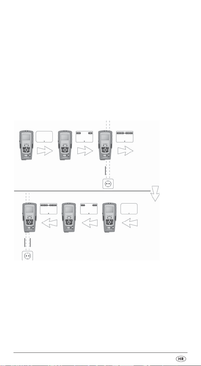
Measuring distances
1. Slide the function switch qto „DISTANCE“. The display 2switches itself on.
To switch between the metric and the Anglo-American units of measurement,
press and hold the button MODE 4. Then press the button READ 6and release
both buttons simultaneously. When you release the buttons, the measurement
units change.
Note:
Measurements start at the measurement point 1!
Should the measurement lie outside the measurement range, „Err“ or an illogical
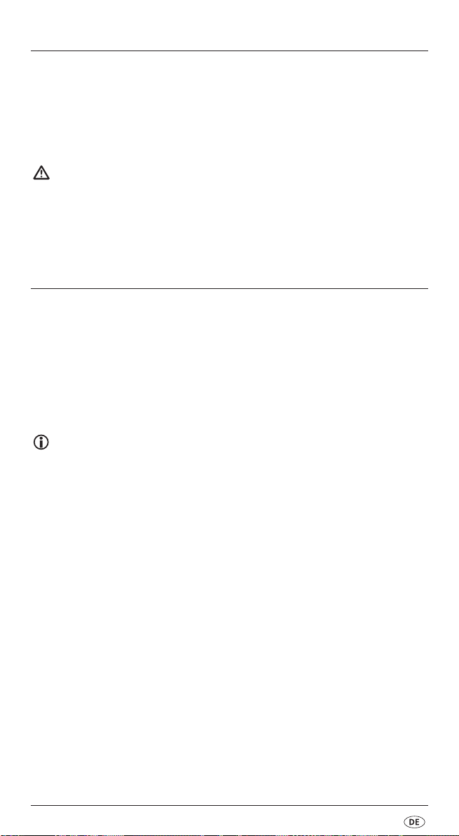
number appear in the display. The measurement range lies between 0,6 m (2’)
and 16 m (53’).
2. Hold the appliance upright towards the wall to which you wish to measure
the distance. The ultrasound sender/receiver
the wall. For this, use the spirit level: The bubble in the glass
between the marking lines (see Fig. 1).
3. Press the button READ
When you hold the button READ
appliance over the surface to be measured, the appliance continually
measures the distances. These are shown on the display
6
. The distance measured appears in the display 2.
6
pressed down and slowly move the
- 5 -
0
must be at a right-angle to
8
must stand
2
.
Page 9

Take note of the following illustrations:
Fig. 1 Fig. 2
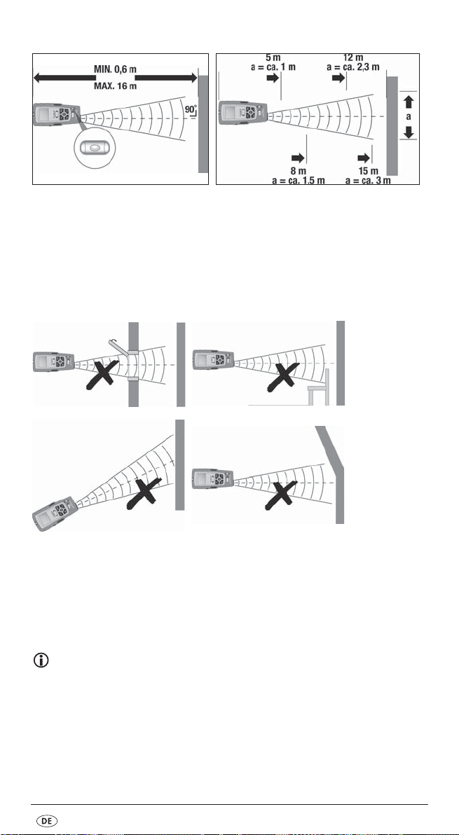
The further you are from the wall, the wider is the area (a) that the MultiMeasurement Detector must measure by ultrasound (Fig. 2). Therefore take care
that the Manifold Measurer is always directed at a right angle towards a level
surface (Fig. 1 and 3). Ensure that there are no objects positioned within the
measurement area.
False!
(Fig. 3)
The display illumination glows during the measurement. If a button is not pressed
within ca.15 seconds, the illumination extinguishes. After a further ca. 15 seconds
the diplay itself switches off. Press the button READ
the illumination.
6
, to reactivate the display and
Note:
Inaccurate measurements can also occur through a weak battery.
If the battery is too weak, the battery symbol appears in the display.
- 6 -
Page 10

Adding distances together
You can add the measured distances together:
1. Measure the first distance as described.
2. Press the button +/=
r
. In the display 2, „+“ appears and the distance
measured carries itself over to the lower line.
3. Measure the next distance. The newly measured distance is shown in the
upper line.
4. Once again, press the button +/=
r
. The new measurement is added
to the old measurement in the lower line.
5. Repeat steps 2 to 4 to add further measurements.
6. When you wish to leave the addition mode, press the button MODE
4
All values are erased.
Measuring areas
1. Slide the function switch qto „DISTANCE“.
The display
2. Press the button MODE
3. Press the button READ
the measured length appears and „W“ (Width) starts to flash.
4. Press the button READ
appears on the upper line and the result of the area calculation in the
lower line.
Adding areas together
1. Measure an area as described in the section „Measuring areas“.
2. Press the button M
The area measured is now saved.
3. Press the button MODE
measurement.
4. Measure the next area.
5. Press the button +/=
6. Press the button RM
lower line.
7. Press the button +/=
the result is shown in the lower line.
8. Repeat the steps 2 to 7 to add in further measurement values.
9. When you wish to leave the addition mode, press the button MODE
All values are erased.
2
switches itself on.
6
6
7
. „M+“ appears in the display 2.
r
. A „+“ appears in the display 2.
w
. The result of the first measurement is shown in the
r
4
once. In the display 2flashes „L“ (Length).
, to measure the length. In the upper line
to measure the width. The measured width
4
. The appliance is now ready for the second
. Both measurements are added together and
4
.
.
- 7 -
Page 11

Measuring volumes
1. Slide the function switch qto „DISTANCE“.
The display
2. Press the button MODE
3. Press the button READ
measured length appears and „W“ (Width) starts to flash.
4. Press the button READ
measured width appears and „H“ (Height) starts to flash.
5. Press the button READ
in the upper line. In the lower line appears the result of the volume calculation.
Adding volumes together
1. Measure a volume as described in the section „Measuring volumes“.
2. Press the button M
The volume measured is now saved.
3. Press the button MODE
measurement.
4. Measure the next volume.
5. Press the button +/=
6. Press the button RM
lower line.
7. Press the button +/=
the result is shown in the lower line.
8. Repeat the steps 2 to 7 to add in further measurement values.
9. When you wish to leave the addition mode, press the button MODE
All values are erased.
2
switches itself on.
4
6
6
6
7
. „M+“ appears in the display 2.
4
r
. A „+“ appears in the display 2.
w
. The result of the first measurement is shown in the
r
. Both measurements are added together and
twice. In the display 2flashes „L“ (Length).
, to measure the length. In the upper line the
to measure the width. In the upper line the
to measure the height. The measured height appears
. The appliance is now ready for the second
4
.
Locating concealed objects
Notice:
• Before using the appliance for this task, first test it by locating a pipeline
or electrical power cable at a known position.
• In cases of doubt, always ask a qualified building contractor.
Attention!
Should the appliance find a live wire carrying alternating current,
appears in the display. Under no circumstances should you drill at this
location! Danger of electric shock!
- 8 -
Page 12

The locating of concealed objects is the same in all three modes (STUD = wood,
AC WIRE = live electric power cables, METAL = metal).
1. Slide the function switch
2. Slide the material switch
q
to „DETECTOR“.
3
to STUD, AC WIRE or METAL.
3. First of all, the appliance must be calibrated. Place it flat against the wall
where you wish to search for concealed objects.
4. Press and hold the button PUSH
z
until the signal tone hums.
The appliance has now adjusted itself to the wall thickness.
Continue to keep the button PUSH
z
pressed down.
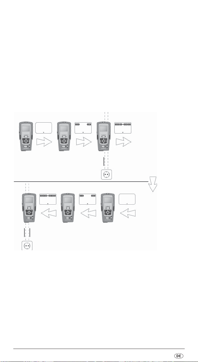
5. Move slowly along the wall with the appliance. As the arrows in the
display move closer to the centre of the display, you are getting closer
to the concealed object. When the arrows touch and a constant signal
tone is heard, mark this position (see Fig. 4).
Fig. 4
6. Now repeat the procedure, but this time approach the object from the other
side. As soon as the signal tone sounds, mark this position (see Fig. 4).
The concealed object runs between these two positions.
- 9 -
Page 13

Locating wood objects
1. Proceed with the search for wood objects as described in the section
„Locating concealed objects“.
2. When the Multi-Measurement Detector has found an object, mark it.
To be sure that the object is wood, slide the material switch
3. Now search in the same position for metal. Should the Multi-Measurement
Detector not find anything, then the object is wood. Should it find something,
then the object is metal.
In this case, search again at a different position in the mode „STUD“ and repeat
steps 1 to 3.
3
to METAL.
Laser marking
The appliance contains a Class 2 laser. NEVER direct the laser beam at
people or animals. NEVER look directly into the laser. The laser can cause
serious eye damage.
You can use laser marking for the exactly horizontal positioning of pictures,
shelves etc.
1. Place the function switch
q
to „LASER“. A laser line is projected.
Horizontal laser line
Attention!
Exercise caution with the holding pins. They are sharp and can cause injuries.
1. Hold the Manifold Measurer horizontally against the wall and align it with
the assistance of the spirit level 8. The air bubble must stand between the
two marking lines.
2. Push both of the holding pins (
The pins lightly bore themselves into the wall so that the appliance
does not fall to the floor. The laser throws a horizontal line onto the wall.
5 + e
) buttons firmly downwards.
Note:
The holding pins do not function on stone or metal walls.
The walls must have a soft upper surface.
- 10 -
Page 14

Vertical laser line
1. Secure a strong thread in the eyelet above the measurement point 1.
2. Hang the Multi-Measurement Detector on the wall at the position where
you want to project the vertical line. The Manifold Measurer hangs like
a plumbline, perpendicularly downwards. The laser throws a vertical
line onto the wall.
Battery display
A battery symbol appears in the display 2when the battery is weak resp. almost
discharged. Replace the battery as soon as possible (see section „Inserting the
battery“). If you do not, the measurements will be false.
Cleaning and storage
• Store the appliance at a dry and frost-free location.
• If you do not intend to use the appliance for an extended period,
remove the battery from the battery compartment.
• Clean the appliance with a soft, dry cloth.
• Do not use chemical or abrasive cleaning agents.
These could damage the housing.
Disposal
Do not dispose of the appliance in your normal domestic waste.
This product is subject to the European guideline 2012/19/EU.
Dispose of the appliance through an approved disposal centre or at your
community waste facility. Observe the currently applicable regulations.
In case of doubt, please contact your waste disposal centre.
Battery disposal!
Batteries may not be disposed of with normal domestic waste.
All consumers are statutorily obliged to dispose of batteries at
the collection point in their community/district or with the original supplier.
The purpose of this obligation is to ensure that batteries can be disposed of
in an environmentally friendly manner. Only dispose of batteries when they
are fully discharged.
Dispose of all packaging materials in an environmentally
friendly manner.
- 11 -
Page 15
Warranty & Service
The warranty for this appliance is for 3 years from the date of purchase. The appliance has been manufactured with care and meticulously examined before delivery. Please retain your receipt as proof of purchase. In the event of a warranty
claim, please make contact by telephone with our Service Department. Only in
this way can a post-free despatch for your goods be assured.
The warranty covers only claims for material and manufacturing defects, but not
for transport damage, for wearing parts or for damage to fragile components,
e.g. buttons or batteries. This product is for private use only and is not intended
for commercial use. The warranty is void in the case of abusive and improper
handling, use of force and internal tampering not carried out by our authorized
service branch. Your statutory rights are not restricted in any way by this warranty.
The warranty period will not be extended by repairs made under warranty. This
applies also to replaced and repaired parts. Any damage and defects extant on
purchase must be reported immediately after unpacking the appliance, at the latest, two days after the purchase date. Repairs made after the expiration of the
warranty period are subject to payment.
Service Great Britain
Tel.: 0871 5000 720 (£ 0.10/Min.)
E-Mail: kompernass@lidl.co.uk
IAN 107555
Service Cyprus
Tel.: 8009 4409
E-Mail: kompernass@lidl.com.cy
IAN 107555
Hotline availability:
Monday to Friday 08:00 - 20:00 (CET)
Importer
KOMPERNASS HANDELS GMBH
BURGSTRASSE 21
44867 BOCHUM, GERMANY
www.kompernass.com
- 12 -
Page 16

SADRŽAJ STRANA
Upotreba u skladu sa namjenom 14
Sigurnosne napomene 14
Tehnički podaci 16
Opis uređaja 16
Obim isporuke 16
Raspakiranje 16
Umetanje baterije 17
Mjerenje rastojanja 17
Mjerenje površina 19
Mjerenje zapremine 20
Pronalaženje prekrivenih objekata 20
Laserska oznaka 22
Baterijski prikaz 23
Čuvanje i čišćenje 23
Zbrinjavanje 23
Jamstvo & servis 24
Uvoznik 24
Upute za rukovanje prije prve upotrebe pažljivo pročitajte i sačuvajte ih za kasnije korištenje. Ukoliko uređaj dajete trećim osobama, priložite i ove upute.
- 13 -
Page 17
VIŠENAMJENSKI DETEKTOR
PMDL 5 A1
Upotreba u skladu sa namjenom
Mjerni detektor sa laserom je predviđen za pronalaženje električnih vodova,
metalnih i drvenih objekata, za projiciranje laserskih linija, za izračunavanje
površina i zapremina, te za mjerenje odstojanja. Ovaj uređaj je predviđen
samo za privatnu uporabu. Ne koristite ga u komercijalne svrhe. Svaki drugi ili
širi oblik korištenja smatra se nenamjenskim i može dovesti do oštećenja i ozljeda. Za štete uzrokovane manipulacijom laserskog uređaja, kao i odašiljača/
prijemnika ultrazvuka, te nepridržavanjem sigurnosnih napomena proizvođač
ne preuzima nikakvu odgovornost.
Sigurnosne napomene
Optimalan i siguran rad sa multidetektorom je moguć samo onda, kada u potpunosti pročitate i uvažite upute za uporabu i sigurnosne napomene i kada se strogo pridržavate svih naputaka sadržanih u njima.
Opasnost od ozljeđivanja!
• Uređaj ne upotrebljavajte na mjestima, na kojima postoji opasnost od
požara ili od eksplozije, na primjer u blizini zapaljivih plinova ili tekućina.
• Ovaj uređaj smiju koristiti djeca stare 8 godina ili više, kao i osobe sa smanjenim fizičkim, senzornim ili mentalnim sposobnostima ili pomanjkanjem iskustva i/ili znanja, ukoliko su pod nadzorom ili su primile poduku o sigurnom rukovanju ure?ajem te su razumjele opasnosti koje proizlaze iz
uporabe uređaja. Djeca se ne smiju igrati ure?ajem. Čišćenje i servisiranje
ne smiju obavljati djeca bez odgovarajućeg nadzora.
• Vrlo oprezno rukujte sa iglama za držanje. One su vrlo oštre i mogu
izazvati ozljede.
Upozorenje od oštećenja na uređaju!
• Uređaj ne izložite kiši. Ne koristite ga u vlažnom ili mokrom okruženju.
• Ne postavljajte posude napunjene vodom, primjerice vaze, na uređaj.
• Ne postavljajte otvorene izvore plamena, kao na primjer svijeće, na uređaj.
- 14 -
Page 18
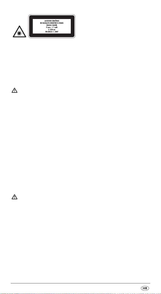
Uređaj sadrži laser klase 2. Laser nikada ne uperite u osobe ili životinje. Nikada
ne gledajte neposredno u laser. Laser može izazvati oštećenje oka.
• Laser ne uperite u snažno reflektirajuće metalne površine.
Opasnost uslijed reflektirajućeg svjetla.
• Ne koristite uređaj, da biste ustanovili naizmjeničnu struju u slobodnim,
odnosno neizoliranim vodovima.
• Uređaj ne koristite kao zamjenu za volt-metar.
Napomene u vezi sa netočnim mjernim rezultatima
Uređaj ne može uvijek prepoznati sve cijevi i vodove.
Slijedeći uvjeti mogu prouzrokovati neprecizne rezultate:
– vrlo debele zidne stijenke
– slabe baterije
– duboko postavljeni vodovi ili cijevi
– prekriveni kablovi
– debeli zidovi sa tankim cijevima ili vodovima
– zidovi obloženi metalom
– visok stupanj vlage u zraku
• Ovim uređajem ne možete pronaći vodove u strujnom krugu,
– koji su izolirani od mrežnog napona.
– kroz koje teče istosmjerna struja.
– koji se koriste za računalne ili telekomunikacijske sustave.
• Ovim uređajem ne možete ustanoviti cijevi od plastike i sličnog materijala,
samo metalne cijevi.
Rukovanje sa baterijama:
• Baterije, koje cure, mogu uzrokovati oštećenje uređaja. Kada uređaj ne
koristite duže vrijeme, izvadite baterije.
• Kod baterija koje su iscurile, stavite zaštitne rukavice i pretinac za baterije
očistite pomoću suhe krpe.
• Baterije ne smiju dospjeti u dječje ruke. Djeca bi baterije mogla staviti u usta
i progutati. Ukoliko dođe do gutanja baterije, odmah potražite liječničku pomoć.
- 15 -
Page 19

Tehnički podaci
Mjerač rastojanja pomoću ultrazvuka
Pronalaženje: Vodova električne energije,
metala, drveta
Klasa lasera: 2
Maks. Izlazna snaga
(P.maks): < 1mW
Valna dužina (λ): 650 nm
u skladu sa EN60825-1:2007
Napajanje: 9 V blok-baterija
Izjava o sukladnosti za ovaj proizvod dostupna je na internet stranici www.lidl.hr.
Opis uređaja
1
Mjerna točka
2
Display
3
Prekidač odabira materijala (STUD/AC WIRE/METAL)
4
Gumb MODE
5
Gumb za igle držaće
6
Gumb READ
7
Gumb M (Memory)
8
Libela
9
Izlazni otvor lasera
0
Ultrazvučni odašiljač/prijemnik
q
Funkcijski prekidač (LASER/DETECTOR/DISTANCE)
w
Gumb RM (Read Memory)
e
Gumb za igle držače
r
Gumb +/=
t
Pretinac za baterije
z
Gumb PUSH
Obim isporuke
• Višenamjenski detektor
• 9 V Blok-baterija
• Upute za uporabu
Raspakiranje
Izvadite mjerni detektor iz pakiranja. Uklonite sve transportne osigurače i sav
materijal ambalaže. Uklonite zaštitnu foliju sa displaya
- 16 -
2
.
Page 20

Umetanje baterije
1. Otvorite pretinac za baterije tna stražnjoj strani mjernog detektora.
2. Blok-bateriju od 9V stavite na odgovarajuće kontakte. Obratite pažnju
na ispravan polaritet.
3. Traku za vađenje baterije postavite ispod blok-baterije napona 9V,
pa bateriju utisnite u pretinac
t
.
Oprez!
Obratite pažnju na to, da ne dođe do gnječenja kabela.
U protivnom uređaj može biti nepopravljivo oštećen.
4. Zatvorite pretinac za baterije t. Poklopac pretinca mora čujno
uleći u ležište.
Mjerenje rastojanja
1. Gurnite funkcijski prekidač qu položaj „DISTANCE“. Display 2se uključuje.
Za prebacivanje između metričkih i angloameričkih mjernih jedinica pritisnite
i držite tipku MODE 4. Zatim pritisnite tipku READ 6i istovremeno pustite
obje tipke. Kada otpustite tipke, mjerne jedinice se mijenjaju.
Napomena:
Mjerenje započinje na mjernoj točci 1!
Ukoliko se mjerenje nalazi izvan mjernog područja, na displayu se pojavljuje dojava
„Err“ ili nelogičan broj. Mjerno područje se nalazi između 0,6m (2 ’) i16 m (53’).
2. Uređaj držite vodoravno pred zid, prema kojem želite izmjeriti odstojanje.
Ultrazvučni odašiljač/prijemnik 0mora pod pravim kutom biti usmjeren
prema zidu. U tu svrhu koristite vodenu vagu: Mjehur u libeli
pozicioniran između dvije crte (vidi sliku 1).
3. Pritisnite gumb READ
Ako gumb READ
površine koju želite izmjeriti, uređaj će kontinuirano mjeriti razdaljine.
Ove razdaljine će na displayu
6
. U displayu 2se pojavljuje izmjereno odstojanje.
6
držite pritisnut i uređajem polako prelazite preko
2
biti prikazane.
- 17 -
8
mora biti
Page 21
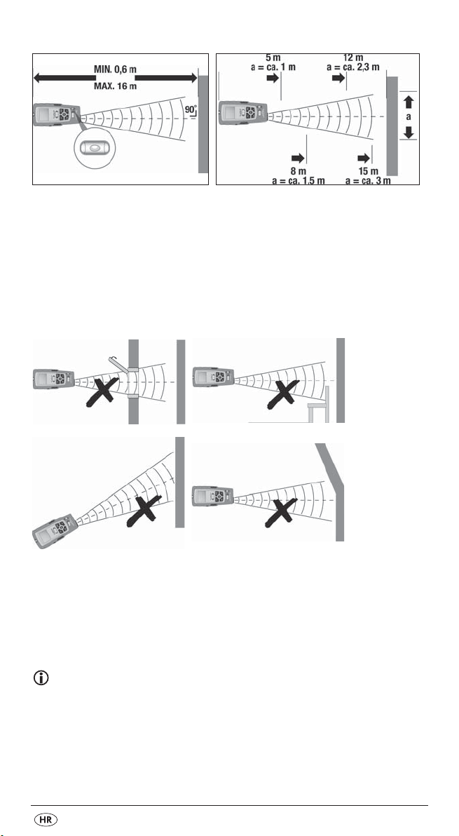
Obratite pažnju na slijedeće slike:
Slika1 Slika 2
Što se nalazite dalje od zida, to će šira biti površina (a), koju mjerni detektor
mjeri pomoću ultrazvuka (slika 2). Iz tog razloga uzmite u obzir, da mjerni
detektor uvijek treba biti usmjeren na ravnu površinu, i to pod kutom od
90 stupnja (slike 1 i 3). Molimo uzmite u obzir, da se ne smiju nikakvi
predmeti nalaziti u mjernom području.
Neispravno!
Slika 3
Za vrijeme mjerenja svijetli osvjetljenje u displayu. Nakon što prođe ca.15 sekundi
be da pritisnete ijedan gumb, osvjetljenje se gasi. Nakon daljnjih ca.15 sekundi
isključiti će se prikaz. Pritisnite gumb READ
i osvjetljenje.
6
, kako biste ponovo aktivirali prikaz
Napomena:
Netočni rezultati mjerenja nastaju uslijed uporabe preslabih baterija.
Ukoliko je baterija previše slaba, na displayu se pojavljuje simbol baterija.
- 18 -
Page 22

Zbrajanje razdaljina
Izmjerene razdaljine možete zbrojiti:
1. Izmjerite prvo rastojanje na gore opisani način.
2. Pritisnite gumb +/=
r
. U displayu 2se pojavljuje „+“, a izmjerena daljina
se prenosi na donji red.
3. Izmjerite slijedeće rastojanje. Novoizmjereno rastojanje biti će prikazano u
gornjem redu.
4. Ponovo pritisnite gumb +/=
r
. Nova mjerna vrijednost će biti pridodana
staroj mjernoj vrijednosti u donjem redu.
5. Ponovite korake 2 do 4, kako biste pribrojili daljnje mjerne vrijednosti.
6. Ako želite napustiti modus zbrajanja, pritisnite gumb MODE
4
.
Sve vrijednosti će biti izbrisane.
Mjerenje površina
1. Gurnite funkcijski prekidač qu položaj „DISTANCE“. Display 2se uključuje.
2. Pritisnite gumb MODE
(Length = dužina).
3. Pritisnite gumb READ
pojavljuje izmjerena dužina i „W“ (Width = širina) počinje treptati.
4. Pritisnite gumb READ
pojavljuje izmjerena širina, a u donjem redu rezultat izračunavanja površine.
Zbrajanje površina
1. Izmjerite povšinu na način opisan u poglavlju „Mjerenje površina“.
2. Pritisnite gumb M
Izmjerena površina ostaje pohranjena.
3. Pritisnite gumb MODE
4. Izmjerite slijedeću površinu.
5. Pritisnite gumb +/=
6. Pritisnite gumb RM
7. Pritisnite gumb +/=
u donjem redu.
8. Ponovite korake 2 do 7, ako želite pribrojiti još dodatne mjerne vrijednosti.
9. Ako želite napustiti modus zbrajanja, pritisnite gumb MODE
Sve vrijednosti se brišu.
4
jedanput. U displayu 2trepti „L“
6
, kako biste izmjerili dužinu. U gornjem redu se
6
, da biste izmjerili širinu. U gornjem redu se
7
. U displayu 2se pojavljuje „M+“.
4
. Uređaj je sada spreman za drugo mjerenje
r
. Oznaka „+“ se pojavljuje na displayu 2.
w
. U donjem redu se prikazuje rezultat prvog mjerenja.
r
. Dva mjerenja se zbrajaju, a rezultat će biti prikazan
4
.
- 19 -
Page 23
Mjerenje zapremine
1. Gurnite funkcijski gumb qu položaj „DISTANCE“. Display 2se uključuje.
2. Pritisnite gumb MODE
3. Pritisnite gumb READ
pojavljuje izmjerena dužina, i oznaka „W“ (Width = širina) počinje treptati.
4. Pritisnite gumb READ
ljuje izmjerena širina, a oznaka „H“ (Height = visina) počinje treptati.
5. Pritisnite gumb READ
izmjerena visina. U donjem redu se pojavljuje rezultat proračuna zapremine.
Zbrajanje zapremine
1. Izmjerite zapreminu na način opisan u poglavlju „Mjerenje zapremine“.
2. Pritisnite gumb M
Izmjerena zapremina je pohranjena.
3. Pritisnite gumb MODE
4. Izmjerite slijedeću zapreminu.
5. Pritisnite gumb +/=
6. Pritisnite gumb RM
7. Pritisnite gumb +/=
donjem redu.
8. Ponovite korake 2 do 7, da biste pribrojili daljnje mjerne vrijednosti.
9. Ako želite napustiti modus zbrajanja, pritisnite gumb MODE
Sve vrijednosti se brišu.
4
dva puta. U displayu 2trepti „L“ (Length = dužina).
6
, da biste izmjerili dužinu. U gornjem redu se
6
, da biste izmjerili širinu. U gornjem redu se pojav-
6
, da biste izmjerili visinu. U gornjem redu se pojavljuje
7
. U displayu 2se pojavljuje „M+“.
4
. Uređaj je sada spreman za drugo mjerenje.
r
. Oznaka „+“ se pojavljuje u displayu 2.
w
. U donjem redu će biti prikazan rezultat prvog mjerenja.
r
. Dva mjerenja se zbrajaju, a rezultat se pokazuje u
4
.
Pronalaženje prekrivenih objekata
Napomene:
• Prije uporabe uređaj ispitajte na taj način, što ćete pomoću njega
prepoznati poznatu cijev, odnosno poznat električni vod.
• U slučaju dvojbe uvijek upitajte kvalificiranog građevinskog poduzetnika.
Oprez!
Ukoliko uređaj pronađe vod, koji provodi naizmjeničnu struju, pojaviti će se u
displayu . Niukom slučaju ne bušite na tom mjestu! Opasnost od strujnog udara!
- 20 -
Page 24
Postupak pronalaženja prekrivenih objekata je u sva tri modusa (STUD = drvo,
AC WIRE = vodovi pod naponom, METAL = Metal) jednak.
1. Gurnite funkcijski gumb
2. Gurnite prekidač za podešavanje materijala
q
na položaj „DETECTOR“.
3
na položaj STUD,
AC WIRE ili METAL.
3. Prvo morate kalibrirati mjerni detektor. Postavite ga na zid, i to na mjestu
na kojem želite tražiti prekrivene objekte.
4. Pritisnite i držite pritisnut gumb PUSH
z
, sve dok se signalni zvuk ne ugasi.
Uređaj se sada prilagodio debljini zidne stijenke. I dalje držite pritisnut
gumb PUSH
z
.
5. Polako se sa mjernim detektorom krećite po zidu. Kada se strelice na
displayu približavaju točci, tada se približavate traženom objektu.
Kada su strelice kompletne, a uz to se čuje dugi signalni zvuk, označite
dostignuti položaj (vidi sliku 4).
Slika 4
6. Postupite na isti način, ali se sada objektu približite sa druge strane.
Čim se začuje signalni zvuk, markirajte dostignuti položaj (vidi sliku 4).
Traženi objekt se nalazi između ovih pozicija.
- 21 -
Page 25
Traženje drvenih objekata
1. Prilikom traženja drvenih objekata postupite na način opisan u poglavlju
„Pronalaženje prekrivenih objekata“.
2. Kada je mjerni detektor pronašao objekt, označite ga. Kako biste bili sigurni,
da se objekt sastoji od drveta, prekidač za odabir materijala prebacite u
3
položaj
3. Sada na istome mjestu potražite metal. Ukoliko mjerni detektor ništa ne
nađe, to znači da je objekt od drveta Ako mjerni detektor pronađe nešto,
traženi objekt se sastoji od metala.
U tom slučaju potražite na drugom mjestu u modusu „STUD“ i ponovite korake
1 do 3.
METAL.
Laserska oznaka
U sklopu ovog uređaja se nalazi laser kategorije 2.
Laser nikada ne smijete usmjeriti na osobe ili životinje.
Nikada ne gledajte direktno u laser. Laser može izazvati oštećenja oka.
Lasersko označavanje možete koristiti, da biste izravnali slike, ormare itd.
i postavili ih okomito odnosno vodoravno.
1. Postavite funkcijski prekidač
Projicirati će se laserska linija.
q
na položaj „LASER“.
Vodoravna laserska linija
Oprez!
Oprezno rukujte sa iglama držačima.
One su vrlo šiljate i mogu izazvati ozljede.
1. Mjerni detektor prislonite vodoravno na zid i izravnajte ga pomoću
8
libele
. Mjehur sa vodom se mora nalaziti između dvije oznake.
2. Gurnite dva gumba za igle držače (
se blago zabosti u zid, tako da mjerni detektor ne može pasti na pod.
Laser baca vodoravnu liniju na zid.
5 +e
) čvrsto prema dolje. Igle će
Napomena:
Igle držači ne mogu funkcionirati na zidovima od kamena ili metala.
Zidovi moraju imati mekanu površinu.
- 22 -
Page 26

Okomita laserska linija
1. Pričvrstite jedan konac na omči iznad mjerne točke 1.
2. Objesite mjerni detektor na zid, na kojem želite projicirati okomitu liniju.
Mjerni detektor će visiti vertikalno prema dolje, kao visak.
Laser projicira vertikalnu liniju na zidu.
Baterijski prikaz
U displayu 2se pojavljuje simbol baterije, kada baterija postane previše slaba.
U tom slučaju što prije trebate izvršiti zamjenu baterije (vidi poglavlje „Umetanje
baterije“). U protivnom rezultati mjerenja neće biti točni.
Čuvanje i čišćenje
• Uređaj čuvajte na suhom mjestu, na kojem nema mraza.
• Ako uređaj duže vrijeme ne koristite, bateriju izvadite iz pretinca za baterije.
• Čišćenje uređaja vršite pomoću suhe i meke krpe.
• Ne upotrebljavajte kemijska sredstva za čišćenje ili sredstva za ribanje.
Ova sredstva mogu oštetiti kućište.
Zbrinjavanje
Uređaj nikako ne bacajte u obično kućno smeće. Ovaj pzoizvod
spada u važnost uredbe evropske direktive 2012/19/EU.
Uređaj zbrinite preko autoriziranog poduzeća za zbrinjavanje otpada ili
preko Vašeg komunalnog poduzeća.
Obratite pažnju na aktualno važeće propise. U slučaju dvojbe se povežite sa svojim mjesnim poduzećem za zbrinjavanje otpada.
Zbrinjavanje baterija!
Baterije ne smiju biti zbrinute sa kućnim smećem. Svaki potrošač je zakonski
obavezan, baterije/akumulatore predati na sabirnom mjestu svoje općine,
dijela grada ili u trgovini.
Ova obaveza služi za to, da baterije mogu biti zbrinute na način neškodljiv
za okoliš. Baterije/akumulatore vratite isključivo u ispražnjenom stanju.
Sve materijale ambalaže zbrinite na način neškodljiv za okoliš.
- 23 -
Page 27
Jamstvo & servis
Na ovaj uređaj vrijedi jamstvo u trajanju od 3 godine od datuma kupovine.
Uređaj je pažljivo proizveden i prije isporuke brižljivo kontroliran. Molimo sačuvajte blagajnički račun kao dokaz o kupnji. Molimo da se u slučaju ostvarivanja
prava na jamstvo telefonski povežete sa Vašom servisnom ispostavom. Samo na
taj način vaša roba može biti besplatno uručena.
Jamstvo vrijedi samo za greške materijala i izrade, a ne za transportne štete, potrošne dijelove ili oštećenja lomljivih dijelova, na primjer prekidača ili baterija.
Proizvod je namijenjen isključivo za privatnu, a ne za gospodarstvenu uporabu.
U slučaju nestručnog rukovanja, rukovanja protivnog namjeni uređaja, primjene
sile i zahvata, koji nisu izvršeni od strane našeg ovlaštenog servisnog predstavništva, važenje jamstva prestaje. Vaša zakonska prava ovim jamstvom ostaju netaknuta.
Jamstveni rok se ne produžava uslijed ostvarivanja prava na jamstvo. To vrijedi i
za zamijenjene i popravljene dijelove. Eventualno već prilikom kupovine prisutna
oštećenja i nedostaci moraju biti javljena neposredno nakon raspakiranja, ali
najkasnije dva dana nakon datuma kupovine. Popravke vršene nakon isteka
jamstvenog roka podliježu obavezi plaćanja.
Servis Hrvatska
Tel.: 0800 777 999
E-Mail: kompernass@lidl.hr
IAN 107555
Dostupnost deÏurne telefonske linije:
Ponedjeljak do petak od 8:00 - 20:00 sati (SEV)
Uvoznik
Lidl Hrvatska d.o.o. k.d.,
p.p. 61
10020 Novi Zagreb
Proizvođač:
KOMPERNASS HANDELS GMBH
BURGSTRASSE 21
44867 BOCHUM
GERMANY
www.kompernass.com
- 24 -
Page 28

INHALTSVERZEICHNIS SEITE
Bestimmungsgemäßer Gebrauch 26
Sicherheitshinweise 26
Technische Daten 28
Gerätebeschreibung 28
Lieferumfang 28
Auspacken 28
Batterie einlegen 29
Messen von Entfernungen 29
Messen von Flächen 31
Messen von Volumen 32
Aufspüren von verdeckten Objekten 32
Lasermarkierung 34
Batterieanzeige 35
Aufbewahrung und Reinigung 35
Entsorgen 35
Garantie und Service 36
Importeur 36
Lesen Sie die Bedienungsanleitung vor der ersten Verwendung aufmerksam durch und
heben Sie diese für den späteren Gebrauch auf. Händigen Sie bei Weitergabe des
Gerätes an Dritte auch die Anleitung aus.
- 25 -
Page 29

MULTIFUNKTIONSDETEKTOR
PMDL 5 A1
Bestimmungsgemäßer Gebrauch
Der Multidetektor mit Laser ist zur Ortung von elektrischen Leitungen, von Metallund Holzobjekten, zum Projizieren von Laserlinien, zum Berechnen von Flächen
und Volumina, sowie zum Messen von Entfernungen konzipiert. Dieses Gerät ist
nur für private Zwecke bestimmt. Gebrauchen Sie es nicht gewerblich. Eine andere oder darüber hinausgehende Benutzung gilt als nicht bestimmungsgemäß und
kann zu Beschädigungen und Verletzungen führen. Für Schäden durch Manipulation an der Lasereinrichtung, sowie am Ultraschallsender/-empfänger und bei
Nichtbefolgen der Sicherheitshinweise wird keine Haftung übernommen.
Sicherheitshinweise
Optimales und sicheres Arbeiten mit dem Multidetektor ist nur möglich, wenn Sie
die Bedienungsanleitung und die Sicherheitshinweise vollständig lesen und die
darin enthaltenen Anweisungen strikt befolgen.
Verletzungsgefahr!
• Benutzen Sie das Gerät nicht an Orten, wo Feuergefahr oder Explosionsgefahr besteht, z. B. in der Nähe von brennbaren Flüssigkeiten oder Gasen.
• Dieses Gerät kann von Kindern ab 8 Jahren und darüber sowie von Personen mit verringerten physischen, sensorischen oder mentalen Fähigkeiten
oder Mangel an Erfahrung und Wissen benutzt werden, wenn sie beaufsichtigt oder bezüglich des sicheren Gebrauchs des Gerätes unterwiesen wurden und die daraus resultierenden Gefahren verstehen. Kinder dürfen nicht
mit dem Gerät spielen. Reinigung und Benutzer-Wartung dürfen nicht von
Kindern ohne Beaufsichtigung durchgeführt werden.
• Gehen Sie vorsichtig mit den Haltenadeln um. Diese sind sehr spitz und
können Verletzungen hervorrufen.
Warnung vor Schäden am Gerät!
• Setzen Sie das Gerät keinem Regen aus. Verwenden Sie das Gerät nicht
in feuchter oder nasser Umgebung.
• Stellen Sie keine mit Flüssigkeiten gefüllten Gefäße, wie z.B. Vasen
auf das Gerät.
• Stellen Sie keine offenen Brandquellen, wie z. B. Kerzen auf das Gerät.
- 26 -
Page 30

Das Gerät enthält einen Klasse-2-Laser. Richten Sie den Laser nie auf Personen
oder Tiere. Blicken Sie nie direkt in den Strahl. Der Laser kann Augenschäden
hervorrufen.
• Richten Sie den Laserstrahl nicht auf stark reflektierende Materialien.
Gefahr durch reflektierendes Licht.
• Verwenden Sie das Gerät nicht, um Wechselspannung in freiliegenden
bzw. nicht isolierten Leitungen festzustellen.
• Verwenden Sie das Gerät nicht als Ersatz für ein Voltmeter.
Hinweise zu ungenauen Messergebnissen
Das Gerät erkennt nicht immer alle Rohre und Leitungen.
Folgende Bedingungen können ungenaue Ergebnisse verursachen:
– sehr dicke Wände
– schwache Batterien
– tiefliegende Leitungen oder Rohre
– abgeschirmte Kabel
– dicke Wände mit dünnen Rohren oder Leitungen
– mit Metall verkleidete Wände
– sehr feuchte Bedingungen
• Mit diesem Gerät lassen sich keine Leitungen in Stromkreisen feststellen,
– die von der Netzspannungsversorgung isoliert sind.
– die von Gleichstrom durchflossen werden.
– die für Computer- oder Telekommunikationssysteme genutzt werden.
• Mit diesem Gerät lassen sich keine Rohre aus Plastik o.ä. feststellen,
nur Rohre aus Metall.
Hinweise zum Umgang mit Batterien
• Auslaufende Batterien können Beschädigungen am Gerät verursachen.
Wenn Sie das Gerät längere Zeit nicht benutzen, entnehmen Sie die Batterien.
• Bei ausgelaufenen Batterien, ziehen Sie Schutzhandschuhe an und reinigen
Sie das Batteriefach mit einem trockenen Tuch.
• Batterien dürfen nicht in die Hände von Kindern gelangen. Kinder könnten
Batterien in den Mund nehmen und verschlucken. Sollte eine Batterie
verschluckt worden sein, suchen Sie sofort einen Arzt auf.
- 27 -
Page 31

Technische Daten
Entfernungsmesser mittels Ultraschall
Aufspüren von: Stromleitungen, Metall, Holz
Laserklasse: 2
Ausgangsleistung (P.max): <1mW
Wellenlänge (λ): 650 nm
gemäß EN60825-1:2007
Spannungsversorgung: 9V-Blockbatterie
Gerätebeschreibung
1
Messpunkt
2
Display
3
Materialschalter (STUD/AC WIRE/METAL)
4
Taste MODE
5
Taste Haltenadel
6
Taste READ
7
Taste M (Memory)
8
Libelle
9
Laser-Austrittsöffnung
0
Ultraschallsender/-empfänger
q
Funktionsschalter (LASER/DETECTOR/DISTANCE)
w
Taste RM (Read Memory)
e
Taste Haltenadel
r
Taste +/=
t
Batteriefach
z
Taste PUSH
Lieferumfang
• Multifunktionsdetektor
• 9 V-Blockbatterie
• Diese Bedienungsanleitung
Auspacken
Entnehmen Sie den Multidetektor aus der Verpackung. Entfernen Sie alle Transportsicherungen und Verpackungsmaterialien. Entfernen Sie die Schutzfolie vom
2
Display
.
- 28 -
Page 32
Batterie einlegen
1. Öffnen Sie das Batteriefach tauf der Rückseite des Multidetektors.
2. Stecken Sie die 9V-Blockbatterie auf die Kontakte. Achten Sie auf die
richtige Polung.
3. Legen Sie das Band zum Herausholen der Batterie unter die 9 V-Blockbatterie und drücken Sie sie in das Batteriefach
t
.
Achtung!
Achten Sie darauf, dass die Kabel nicht eingeklemmt werden.
Das führt zu irreparablen Schäden am Gerät.
4. Schließen Sie das Batteriefach t. Der Batteriefachdeckel muss hörbar einrasten.
Messen von Entfernungen
1. Schieben Sie den Funktionsschalter qauf „DISTANCE“. Das Display
schaltet sich ein.
Um zwischen den metrischen und angloamerikanischen Maßeinheiten zu
wechseln, drücken und halten Sie die Taste MODE 4. Drücken Sie dann die
Taste READ
lösen, wechseln die Maßeinheiten.
6
und lösen Sie beide Tasten gleichzeitig. Wenn Sie die Tasten
2
Hinweis:
Die Messung startet am Messpunkt 1!
Befindet sich die Messung außerhalb des Messbereiches, erscheint im Display
„Err“ oder eine unlogische Zahl. Der Messbereich liegt zwischen 0,6 m (2’)
und 16m (53’).
2. Halten Sie das Gerät waagerecht vor die Wand, zu der Sie die Entfernung
messen wollen. Der Ultraschallsender/-empfänger
Winkel auf die Wand zeigen. Benutzen Sie hierfür die Wasserwaage:
Die Blase in der Libelle
(siehe Abb. 1).
3. Drücken Sie die Taste READ
Entfernung. Wenn Sie die Taste READ
langsam weiter über die zu messende Fläche bewegen, misst das Gerät kontinuierlich die Entfernungen. Diese werden auf dem Display
8
muss zwischen den Markierungsstrichen stehen
6
. Im Display 2erscheint die gemessene
6
gedrückt halten und das Gerät
0
muss im rechten
2
angezeigt.
- 29 -
Page 33
Beachten Sie folgende Abbildungen:
Abb. 1 Abb. 2
Je weiter Sie von der Wand entfernt stehen, umso breiter ist die Fläche (a), die der
Multidetektor mittels Ultraschall misst (Abb. 2). Beachten Sie daher, dass der Multidetektor immer auf eine ebene Fläche im rechten Winkel gerichtet ist (Abb.1 und 3).
Bitte beachten Sie, dass sich keine Gegenstände im Messbereich befinden.
Falsch!
Abb. 3
Während den Messungen leuchtet die Displaybeleuchtung.
Wird ca.15 Sekunden keine Taste gedrückt erlischt die Beleuchtung.
Nach weiteren ca.15 Sekunden erlischt die Anzeige. Drücken Sie die Taste
6
READ
, um die Anzeige und die Beleuchtung wieder zu aktivieren.
Hinweis:
Ungenaue Messergebnisse entstehen auch durch zu schwache Batterien.
Ist die Batterie zu schwach, erscheint das Batterie-Symbol auf dem Display.
- 30 -
Page 34

Addieren von Entfernungen
Sie können gemessene Entfernungen addieren:
1. Messen Sie die erste Entfernung wie beschrieben.
2. Drücken Sie die Taste +/=
r
. Im Display 2erscheint „+“ und die
gemessene Entfernung überträgt sich auf die untere Zeile.
3. Messen Sie die nächste Entfernung. Die neu gemessene Entfernung
wird in der oberen Zeile angezeigt.
4. Drücken Sie erneut die Taste +/=
r
. Der neue Messwert wird auf
den alten Messwert in der unteren Zeile addiert.
5. Wiederholen Sie die Schritte 2 bis 4, um weitere Messwerte zu addieren.
6. Wenn Sie den Additions-Modus verlassen wollen, drücken Sie die Taste
4
MODE
. Alle Werte werden gelöscht.
Messen von Flächen
1. Schieben Sie den Funktionsschalter qauf „DISTANCE“.
Das Display
2. Drücken Sie die Taste MODE
(Length = Länge).
3. Drücken Sie die Taste READ
In der oberen Zeile erscheint die gemessene Länge und „W“
(Width = Weite) fängt an zu blinken.
4. Drücken Sie die Taste READ
In der oberen Zeile erscheint die gemessene Breite und in der unteren Zeile
das Ergebnis der Flächenberechnung.
2
schaltet sich ein.
4
einmal. Im Display 2blinkt „L“
6
, um die Länge zu messen.
6
, um die Breite zu messen.
Addieren von Flächen
1. Messen Sie eine Fläche, wie im Kapitel „Messen von Flächen“ beschrieben.
2. Drücken Sie die Taste M
Fläche ist gespeichert.
3. Drücken Sie die Taste MODE
Messung.
4. Messen Sie die nächste Fläche.
5. Drücken Sie die Taste +/=
6. Drücken Sie die Taste RM
ersten Messung angezeigt.
7. Drücken Sie die Taste +/=
und das Ergebnis wird in der unteren Zeile angezeigt.
8. Wiederholen Sie die Schritte 2 bis 7, um weitere Messwerte zu addieren.
9. Wenn Sie den Additions-Modus verlassen wollen, drücken Sie die Taste
4
MODE
. Alle Werte werden gelöscht.
7
. Im Display 2erscheint „M+“. Die gemessene
4
. Das Gerät ist nun bereit für die zweite
r
. Ein „+“ erscheint auf dem Display 2.
w
. In der unteren Zeile wird das Ergebnis der
r
. Die beiden Messungen werden addiert
- 31 -
Page 35
Messen von Volumen
1. Schieben Sie den Funktionsschalter qauf „DISTANCE“.
Das Display
2. Drücken Sie die Taste MODE
(Length = Länge).
3. Drücken Sie die Taste READ
Zeile erscheint die gemessene Länge und „W“ (Width = Weite) fängt an
zu blinken.
4. Drücken Sie die Taste READ
Zeile erscheint die gemessene Breite und „H“ (Height = Höhe) fängt an zu
blinken.
5. Drücken Sie die Taste READ
erscheint die gemessene Höhe. In der unteren Zeile erscheint das Ergebnis
der Volumenberechnung.
Addieren von Volumina
1. Messen Sie ein Volumen, wie im Kapitel „Messen von Volumen“
beschrieben.
2. Drücken Sie die Taste M
Das gemessene Volumen ist gespeichert.
3. Drücken Sie die Taste MODE
Messung.
4. Messen Sie das nächste Volumen.
5. Drücken Sie die Taste +/=
6. Drücken Sie die Taste RM
ersten Messung angezeigt.
7. Drücken Sie die Taste +/=
das Ergebnis wird in der unteren Zeile angezeigt.
8. Wiederholen Sie die Schritte 2 bis 7, um weitere Messwerte zu addieren.
9. Wenn Sie den Additions-Modus verlassen wollen, drücken Sie die Taste
MODE
2
schaltet sich ein.
4
zweimal. Im Display 2blinkt „L“
6
, um die Länge zu Messen. In der oberen
6
, um die Breite zu Messen. In der oberen
6
, um die Höhe zu messen. In der oberen Zeile
7
. Im Display 2erscheint „M+“.
4
. Das Gerät ist nun bereit für die zweite
r
. Ein „+“ erscheint auf dem Display 2.
w
. In der unteren Zeile wird das Ergebnis der
r
. Die beiden Messungen werden addiert und
4
. Alle Werte werden gelöscht.
Aufspüren von verdeckten Objekten
Hinweise:
• Testen Sie das Gerät vor dem Gebrauch dadurch, dass Sie ein bekanntes
Rohr bzw. eine bekannte Stromleitung erkennen lassen.
• Fragen Sie in Zweifelsfällen immer einen qualifizierten Bauunternehmer.
Achtung!
Findet das Gerät eine wechselstromführende Leitung, erscheint im
Display . Bohren Sie auf keinen Fall an dieser Stelle! Gefahr durch
elektrischen Schlag!
- 32 -
Page 36
Das Aufspüren von verdeckten Objekten ist in allen drei Modi (STUD = Holz,
AC WIRE = Stromführende Leitungen, METAL = Metall) gleich.
1. Schieben Sie den Funktionsschalter
2. Schieben Sie den Materialschalter
q
auf „DETECTOR“.
3
auf STUD, AC WIRE oder METAL.
3. Zuerst müssen Sie den Multidetektor kalibrieren. Setzen Sie ihn flach auf
die Wand, wo Sie nach verdeckten Objekten suchen möchten.
4. Drücken und halten Sie die Taste PUSH
z
, bis der Signalton verstummt.
Das Gerät hat sich nun auf die Wandstärke eingestellt. Halten Sie die
Taste PUSH
z
weiterhin gedrückt.
5. Fahren Sie langsam mit dem Multidetektor an der Wand entlang.
Wenn sich die Pfeile auf dem Display auf den Punkt zubewegen,
nähern Sie sich dem gesuchten Objekt. Sind die Pfeile komplett und ein
anhaltender Signalton ertönt, markieren Sie diese Position (siehe Abb. 4).
Abb. 4
6. Verfahren Sie nun genauso, nur nähern Sie sich von der anderen Seite
an das Objekt. Sobald der Signalton ertönt, markieren Sie diese Position
(siehe Abb. 4).
Zwischen diesen Positionen verläuft das gesuchte Objekt.
- 33 -
Page 37
Suche nach Holzobjekten
1. Verfahren Sie bei der Suche nach Holzobjekten, wie im Kapitel
„Aufspüren von verdeckten Objekten“ beschrieben.
2. Wenn der Multidetektor ein Objekt gefunden hat, markieren Sie es. Um sicher zu gehen, dass das Objekt aus Holz besteht, schieben Sie den Materialschalter
3. Suchen Sie nun an der selben Stelle nach Metall. Findet der Multidetektor
nichts, so ist das Objekt aus Holz. Findet der Multidetektor etwas, besteht
das Objekt aus Metall.
Suchen Sie in diesem Fall an einer anderen Stelle im Modus „STUD“ und
wiederholen Sie die Schritte 1 bis 3.
3
auf METAL.
Lasermarkierung
Das Gerät enthält einen Klasse-2-Laser. Richten Sie den Laser nie auf
Personen oder Tiere. Blicken Sie nie direkt in den Strahl. Der Laser kann
Augenschäden hervorrufen.
Die Lasermarkierung können Sie benutzen, um Bilder, Schränke, o.ä.
senkrecht bzw. waagerecht auszurichten.
1. Stellen Sie den Funktionsschalter
Eine Laserlinie wird projiziert.
q
auf „LASER“.
Waagerechte Laserlinie
Achtung!
Gehen Sie vorsichtig mit den Haltenadeln um.
Diese sind sehr spitz und können Verletzungen hervorrufen.
1. Halten Sie den Multidetektor waagerecht an die Wand und richten
Sie ihn mit Hilfe der Libelle
Markierungen stehen.
2. Schieben Sie die beiden Tasten Haltenadeln (
Die Nadeln bohren sich leicht in die Wand, so dass der Multidetektor
nicht herunterfällt. Der Laser wirft eine waagerechte Linie an die Wand.
8
aus. Die Blase muss zwischen den beiden
5+e
) fest nach unten.
Hinweis:
Die Haltenadeln funktionieren nicht auf Stein- oder Metallwänden.
Die Wände müssen eine weiche Oberfläche haben.
- 34 -
Page 38
Senkrechte Laserlinie
1. Befestigen Sie einen Faden an der Öse am Messpunkt 1.
2. Hängen Sie den Multidetektor an die Wand, wo Sie die senkrechte Linie
projizieren wollen. Der Multidetektor hängt wie ein Lot senkrecht nach unten.
Der Laser wirft eine senkrechte Linie an die Wand.
Batterieanzeige
Im Display 2erscheint ein Batterie-Symbol, wenn die Batterie schwach wird.
Ersetzen Sie schnellstmöglich die Batterie (siehe Kapitel „Batterie einlegen“).
Ansonsten werden die Messergebnisse verfälscht.
Aufbewahrung und Reinigung
• Bewahren Sie das Gerät an einem trockenen und frostfreien Ort auf.
• Wenn Sie das Gerät für längere Zeit nicht benutzen, entfernen Sie die
Batterie aus dem Batteriefach.
• Reinigen Sie das Gerät mit einem trockenen, weichen Tuch.
• Benutzen Sie keine chemischen oder scheuernden Putzmittel.
Sie können das Gehäuse beschädigen.
Entsorgen
Werfen Sie das Gerät keinesfalls in den normalen Hausmüll.
Dieses Produkt unterliegt der europäischen Richtlinie
2012/19/EU.
Entsorgen Sie das Gerät über einen zugelassenen Entsorgungsbetrieb
oder über Ihre kommunale Entsorgungseinrichtung.
Beachten Sie die aktuell geltenden Vorschriften. Setzen Sie sich im Zweifelsfall mit
Ihrer Entsorgungseinrichtung in Verbindung.
Batterien entsorgen
Batterien dürfen nicht im Hausmüll entsorgt werden. Jeder Verbraucher ist
gesetzlich verpflichtet, Batterien/Akkus bei einer Sammelstelle seiner
Gemeinde/seines Stadtteils oder im Handel abzugeben.
Diese Verpflichtung dient dazu, dass Batterien einer umweltschonenden
Entsorgung zugeführt werden können. Geben Sie Batterien/Akkus nur im
entladenen Zustand zurück.
Führen Sie alle Verpackungsmaterialien einer umweltgerechten
Entsorgung zu.
- 35 -
Page 39
Garantie und Service
Sie erhalten auf dieses Gerät 3 Jahre Garantie ab Kaufdatum. Das Gerät wurde
sorgfältig produziert und vor Anlieferung gewissenhaft geprüft. Bitte bewahren
Sie den Kassenbon als Nachweis für den Kauf auf. Bitte setzen Sie sich im Garantiefall mit Ihrer Servicestelle telefonisch in Verbindung. Nur so kann eine kostenlose Einsendung Ihrer Ware gewährleistet werden. Die Garantieleistung gilt
nur für Material- oder Fabrikationsfehler, nicht aber für Transportschäden, Verschleißteile oder für Beschädigungen an zerbrechlichen Teilen, z. B. Schalter
oder Akkus. Das Produkt ist lediglich für den privaten und nicht für den gewerblichen Gebrauch bestimmt. Bei missbräuchlicher und unsachgemäßer Behandlung,
Gewaltanwendung und bei Eingriffen, die nicht von unserer autorisierten ServiceNiederlassung vorgenommen wurden, erlischt die Garantie. Ihre gesetzlichen
Rechte werden durch diese Garantie nicht eingeschränkt. Die Garantiezeit wird
durch die Gewährleistung nicht verlängert. Dies gilt auch für ersetzte und reparierte Teile. Eventuell schon beim Kauf vorhandene Schäden und Mängel müssen
sofort nach dem Auspacken gemeldet werden, spätestens aber zwei Tage nach
Kaufdatum. Nach Ablauf der Garantiezeit anfallende Reparaturen sind kostenpflichtig.
Service Deutschland
Tel.: 0800 5435 111
(Kostenfrei aus dem dt. Festnetz/Mobilfunknetz)
E-Mail: kompernass@lidl.de
IAN 107555
Service Österreich
Tel.: 0820 201 222 (0,15 EUR/Min.)
E-Mail: kompernass@lidl.at
IAN 107555
Service Schweiz
Tel.: 0842 665566 (0,08 CHF/Min.,
Mobilfunk max. 0,40 CHF/Min.)
E-Mail: kompernass@lidl.ch
IAN 107555
Erreichbarkeit Hotline:
Montag bis Freitag von 8:00 Uhr - 20:00 Uhr (MEZ)
Importeur
KOMPERNASS HANDELS GMBH
BURGSTRASSE 21
44867 BOCHUM, GERMANY
www.kompernass.com
- 36 -
Page 40
KOMPERNASS HANDELS GMBH
BURGSTRASSE 21
44867 BOCHUM
DEUTSCHLAND / GERMANY
www.kompernass.com
Last Information Update · Stanje informacija
Stand der Informationen: 01 / 2015
Ident.-No.: PMDL5A1-012015-2
IAN 107555
7
 Loading...