


 Loading...
Service
Manual
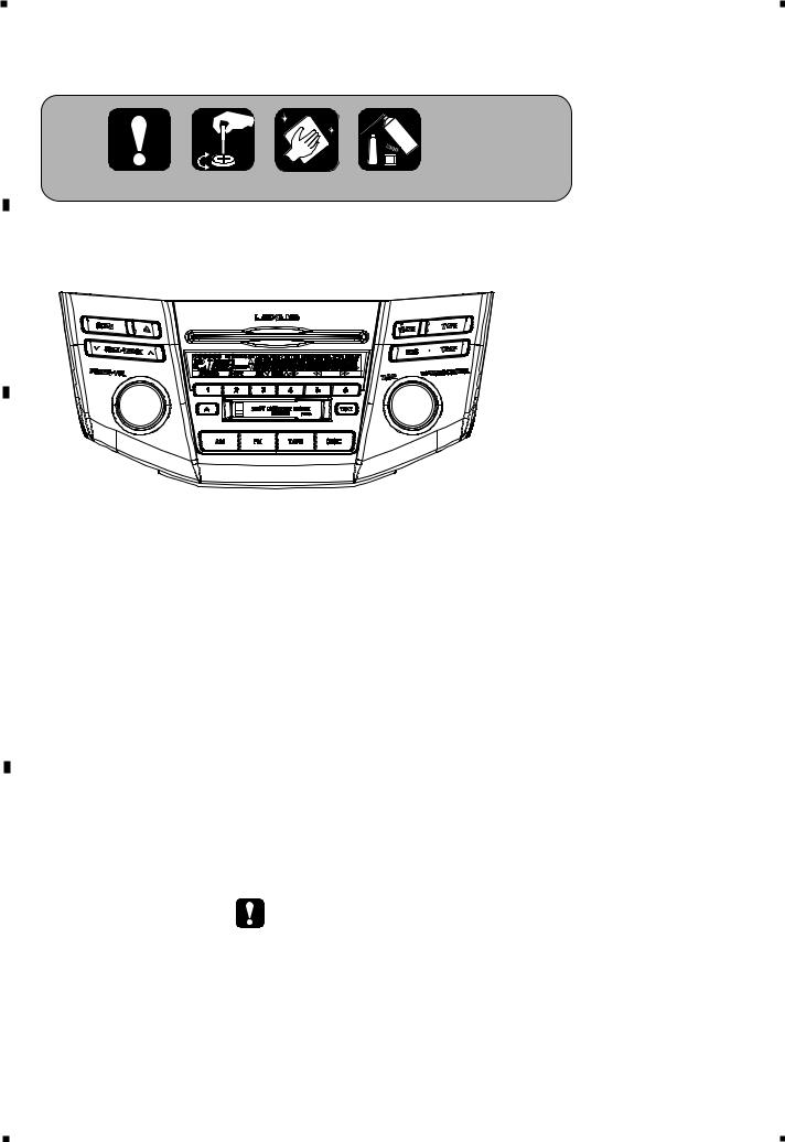
 RX330 AUDIO SYSTEM HEAD UNIT
ORDER NO.
CRT3000
VEHICLE |
DESTINATION |
PRODUCED AFTER |
TOYOTA PART No. |
ID No. |
PIONEER MODEL No. |
LEXUS RX330 |
U.S.A., CANADA |
February 2003 |
86120-48170 |
P6828 |
FX-M8427ZT/UC |
LEXUS RX330 |
U.S.A., CANADA |
February 2003 |
86120-48310 |
P6828 |
FX-M8427ZT-91/UC |
Manufactured for TOYOTA |
|
by PIONEER CORPORATION |
PUB. NO. CRT3000 |
1 |
|
2 |
|
3 |
|
4 |
|
|
|
A
For details, refer to "Important symbols for good services".
FX-M8472ZT/UC(P6828)
B
C
- This service manual should be used together with the following manual(s):
|
|
Model No. |
Order No. |
Mech. Module |
Remarks |
|
|
CX-977 |
CRT2624 |
S9 |
CD Mech. Module:Circuit Description, Mech.Description, Disassembly |
|
|
||||
|
|
||||
|
|
CX-1011 |
CRT2406 |
3L |
Cassette Mech. Module:Mech.Description, Disassembly |
|
|
- Dolby noise reduction manufactured under license from Dolby Laboratories Licensing Corporation. |
|||
D |
"Dolby" and the double-D symbol are trademarks of Dolby Laboratories Licensing Corporation. |
||||
SAFETY INFORMATION
This service manual is intended for qualified service technicians; it is not meant for the casual do-it-yourselfer. Qualified technicians have the necessary test equipment and tools, and have been trained to properly and safely repair complex products such as those covered by this manual.
Improperly performed repairs can adversely affect the safety and reliability of the product and may void the warranty. If you are not qualified to perform the repair of this product properly and safely, you should not risk trying to do so and refer the repair to a qualified service technician.
E
|
- CD section precaution |
|
|
||
|
1. Before disassembling the unit, be sure to turn off the |
2. To protect the pickup unit from electrostatic dis- |
|||
|
|
power. Unplugging and plugging the connectors dur- |
charge during servicing, take an appropriate treat- |
||
|
|
||||
|
|
ing power-on mode may damage the ICs inside the |
ment (shorting-solder) by referring to “the DISAS- |
||
|
|
unit. |
SEMBLY” on page 69. |
||
F |
|
|
3. After replacing the pickup unit, be sure to check the |
||
|
|
grating. (See p.59.) |
|||
|
|
|
|
||
2 |
|
|
|
|
|
|
FX-M8427ZT/UC |
|
|
||
|
|
|
|
|
|
1 |
|
2 |
|
3 |
|
4 |
|
|
|
||||
|
|
|
5 |
|
6 |
|
7 |
|
8 |
|
|
|
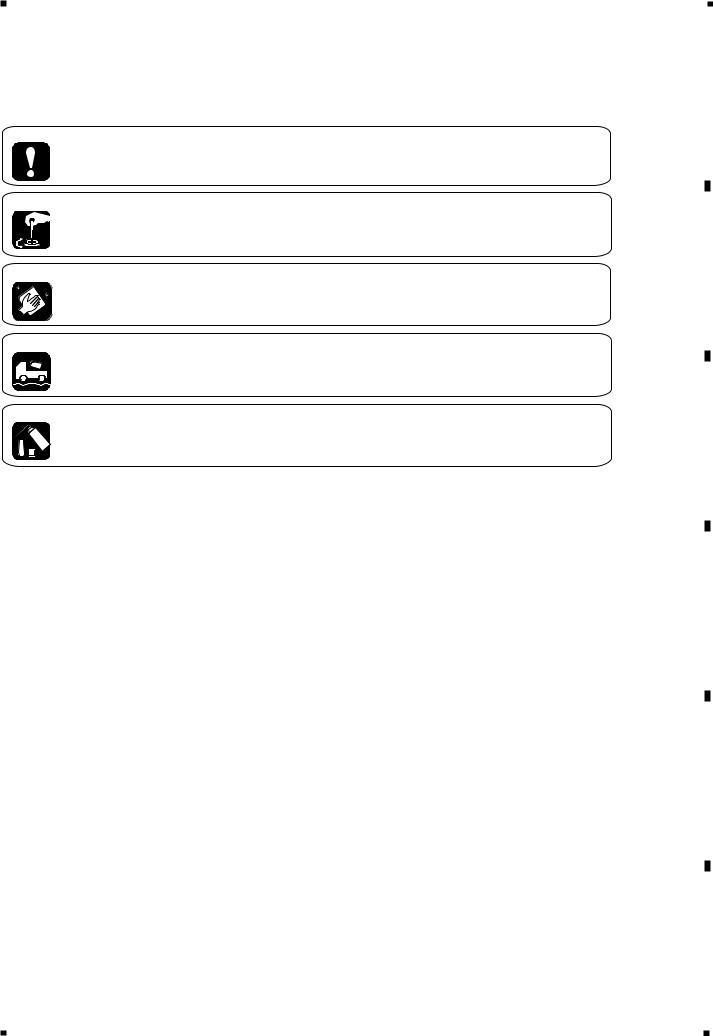
[ Important symbols for good services ]
In this manual, the symbols shown-below indicate that adjustments, settings or cleaning should be made securely. When you find the procedures bearing any of the symbols, be sure to fulfill them:
1. Product safety
You should conform to the regulations governing the product (safety, radio and noise, and other regulations), and should keep the safety during servicing by following the safety instructions described in this manual.
2. Adjustments
To keep the original performances of the product, optimum adjustments or specification confirmation is indispensable. In accordance with the procedures or instructions described in this manual, adjustments should be performed.
3. Cleaning
For optical pickups, tape-deck heads, lenses and mirrors used in projection monitors, and other parts requiring cleaning, proper cleaning should be performed to restore their performances.
4. Shipping mode and shipping screws
To protect the product from damages or failures that may be caused during transit, the shipping mode should be set or the shipping screws should be installed before shipping out in accordance with this manual, if necessary.
5. Lubricants, glues, and replacement parts
Appropriately applying grease or glue can maintain the product performances. But improper lubrication or applying
 glue may lead to failures or troubles in the product. By following the instructions in this manual, be sure to apply the
 prescribed grease or glue to proper portions by the appropriate amount.For replacement parts or tools, the prescribed ones should be used.
FX-M8427ZT/UC |
3 |
|
|
A
B
C
D
E
F
5 |
|
6 |
|
7 |
|
8 |
|
|
|
||||
|
|
|

1 |
|
2 |
|
3 |
|
4 |
|
|
|
A |
CONTENTS |
|
|
SAFETY INFORMATION....................................................................................... |
2 |
|
1. SPECIFICATIONS.................................................................................................. |
5 |
|
2. EXPLODED VIEWS AND PARTS LIST ................................................................. |
6 |
|
2.1 PACKING(FX-M8427ZT-91/UC) ...................................................................... |
6 |
|
2.2 EXTERIOR ....................................................................................................... |
8 |
|
2.3 CD MECHANISM MODULE ......................................................................... |
10 |
|
2.4 CASSETTE MECHANISM MODULE............................................................ |
12 |
|
3. BLOCK DIAGRAM AND SCHEMATIC DIAGRAM ............................................. |
14 |
|
3.1 BLOCK DIAGRAM......................................................................................... |
14 |
|
3.2 OVERALL CONNECTION DIAGRAM(GUIDE PAGE)................................... |
16 |
B |
|
|
|
3.3 KEYBOARD UNIT ......................................................................................... |
22 |
|
3.4 CD MECHANISM MODULE ......................................................................... |
24 |
|
3.5 CASSETTE MECHANISM MODULE............................................................ |
28 |
|
4. PCB CONNECTION DIAGRAM .......................................................................... |
30 |
|
4.1 MAIN UNIT ................................................................................................... |
30 |
|
4.2 KEYBOARD UNIT ......................................................................................... |
34 |
|
4.3 CD MECHANISM MODULE ......................................................................... |
38 |
|
4.4 CASSETTE MECHANISM MODULE............................................................ |
40 |
|
5. ELECTRICAL PARTS LIST .................................................................................. |
42 |
|
6. ADJUSTMENT.................................................................................................... |
50 |
|
6.1 CONNECTION DIAGRAM ............................................................................ |
50 |
C |
|
|
|
6.2 AUDIO, TUNER ADJUSTMENT................................................................... |
54 |
|
6.3 TEST MODE .................................................................................................. |
56 |
|
6.4 CD ADJUSTMENT........................................................................................ |
57 |
|
6.5 CHECKING THE GRATING AFTER CHANGING THE PICKUP UNIT .......... |
59 |
|
6.6 ERROR CODE................................................................................................ |
61 |
|
6.7 AVC-LAN DIAGNOSIS MODE...................................................................... |
65 |
|
7. GENERAL INFORMATION ................................................................................. |
69 |
|
7.1 DIAGNOSIS................................................................................................... |
69 |
|
7.1.1 DISASSEMBLY ........................................................................................ |
69 |
|
7.1.2 CONNECTOR FUNCTION DESCRIPTION .............................................. |
73 |
D |
7.2 PARTS ........................................................................................................... |
74 |
|
7.2.1 IC............................................................................................................... |
74 |
|
7.2.2 DISPLAY ................................................................................................... |
77 |
|
7.3 EXPLANATION ............................................................................................. |
78 |
|
7.3.1 SYSTEM BLOCK DIAGRAM.................................................................... |
78 |
|
7.3.2 OPERATIONAL FLOW CHART ................................................................ |
81 |
|
7.4 CLEANING .................................................................................................... |
82 |
|
8. OPERATIONS...................................................................................................... |
83 |
E |
|
|
F
4 |
FX-M8427ZT/UC |
|
|
1 |
|
2 |
|
3 |
|
4 |
|
|
|
||||
|
|
|

5 |
|
6 |
|
7 |
|
8 |
|
|
|
1. SPECIFICATIONS
General
Power source . . . . . . . . . . . . . . . . . . . . . . . . . . . . . . . . . . . . . . .13.2V(10.5V-16.0V allowable) DC Grounding system . . . . . . . . . . . . . . . . . . . . . . . . . . . . . . . . . . . . . . . . . . . . . . . . . . .Negative type Backup current . . . . . . . . . . . . . . . . . . . . . . . . . . . . . . . . . . . . . . . . . . . . . . . . . . . . . .0.3mA or less Dimensions . . . . . . . . . . . . . . . . . . . . . . . . . . . . . . . . . . . . . . . . . . . . .319(W) x144(H) x174(D)mm Weight . . . . . . . . . . . . . . . . . . . . . . . . . . . . . . . . . . . . . . . . . . . . . . . . . . . . . . . . . . . . . . . . . . . .2.3kg
Cassette player
Tape . . . . . . . . . . . . . . . . . . . . . . . . . . . . . . . . . . . . . . . . . . . . . . .Compact cassette tape(C30-C90) Tape speed . . . . . . . . . . . . . . . . . . . . . . . . . . . . . . . . . . .4.76cm/sec.(+0.14cm/sec., -0.05cm/sec.) Wow and flutter . . . . . . . . . . . . . . . . . . . . . . . . . . . . . . . . . . . . . . . . . . . . . . . .0.2% or less(WRMS) Crosstalk . . . . . . . . . . . . . . . . . . . . . . . . . . . . . . . . . . . . . . . . . . . . . . . . . . . . . . . . . . . .40dB or less Stereo Separation . . . . . . . . . . . . . . . . . . . . . . . . . . . . . . . . . . . . . . . . . . . . . . . . . . . .30dB or more S/N . . . . . . . . . . . . . . . . . . . . . . . . . . . . . . . . . . . . . . . . . . . . . . . . . . . . . . . . . . . . . . . .40dB or more Distortion . . . . . . . . . . . . . . . . . . . . . . . . . . . . . . . . . . . . . . . . . . . . . . . . . . . . . . . . . . . . .3% or less
CD player
System . . . . . . . . . . . . . . . . . . . . . . . . . . . . . . . . . . . . . . . . . . . . . . . . .Compact disc audio system Usable discs . . . . . . . . . . . . . . . . . . . . . . . . . . . . . . . . . . . . . . . . . . . . . . . . . . . . . . . .Compact disc Signal format . . . . . . . . . . . . . . . . . . . . . . . . . . . . . . . . . . . . . . . . . .Sampling frequency : 44.1kHz
. . . . . . . . . . . . . . . . . . . . . . . . . . . . . . . . . . . . . . . . . . . . . . . . .Number of quantization : 16; linear S/N . . . . . . . . . . . . . . . . . . . . . . . . . . . . . . . . . . . . . . . . . . . . . . . . . . . . . . . . . . . . . . . .65dB or more Distortion . . . . . . . . . . . . . . . . . . . . . . . . . . . . . . . . . . . . . . . . . . . . . . . . . . . . . . . . . . . .0.3% or less
FM tuner
Frequency range . . . . . . . . . . . . . . . . . . . . . . . . . . . . . . . . . . . . . . . . . . . . .87.75, 87.9− 107.9 MHz S/N . . . . . . . . . . . . . . . . . . . . . . . . . . . . . . . . . . . . . . . . . . . . . . . . . . . .46dB or more(54dBµ input) Distortion . . . . . . . . . . . . . . . . . . . . . . . . . . . . . . . . . . . . . . . . . . . . . . . . . . . . . . . . . . . .1.5% or less IF interference . . . . . . . . . . . . . . . . . . . . . . . . . . . . . . . . . . . . . . . . . . . . . . . . . . . . . . .80dB or more Image interference . . . . . . . . . . . . . . . . . . . . . . . . . . . . . . . . . . . . . . . . . . . . . . . . . . .35dB or more Stereo Separation . . . . . . . . . . . . . . . . . . . . . . . . . . . . . . . . . . . . . . . . . . . . . .25dB or more(1kHz)
AM tuner
Frequency range . . . . . . . . . . . . . . . . . . . . . . . . . . . . . . . . . . . . . . . . . . . . . . . . . . . . .530-1,710 kHz S/N 20dB usable sensibility . . . . . . . . . . . . . . . . . . . . . . . . . . . . . . . . . . . . . . . . . . . .34dBµ or less S/N . . . . . . . . . . . . . . . . . . . . . . . . . . . . . . . . . . . . . . . . . . . . . . . . . . . . . . . . . . . . . . . .42dB or more Distortion . . . . . . . . . . . . . . . . . . . . . . . . . . . . . . . . . . . . . . . . . . . . . . . . . . . . . . . . . . . .1.5% or less IF interference . . . . . . . . . . . . . . . . . . . . . . . . . . . . . . . . . . . . . . . . . . . . . . . . . . . . . . .55dB or more Image interference . . . . . . . . . . . . . . . . . . . . . . . . . . . . . . . . . . . . . . . . . . . . . . . . . . .45dB or more
A
B
C
D
E
F
FX-M8427ZT/UC |
5 |
|
|
5 |
|
6 |
|
7 |
|
8 |
|
|
|
||||
|
|
|
1 |
|
2 |
|
3 |
|
4 |
|
|
|
A
B
C
D
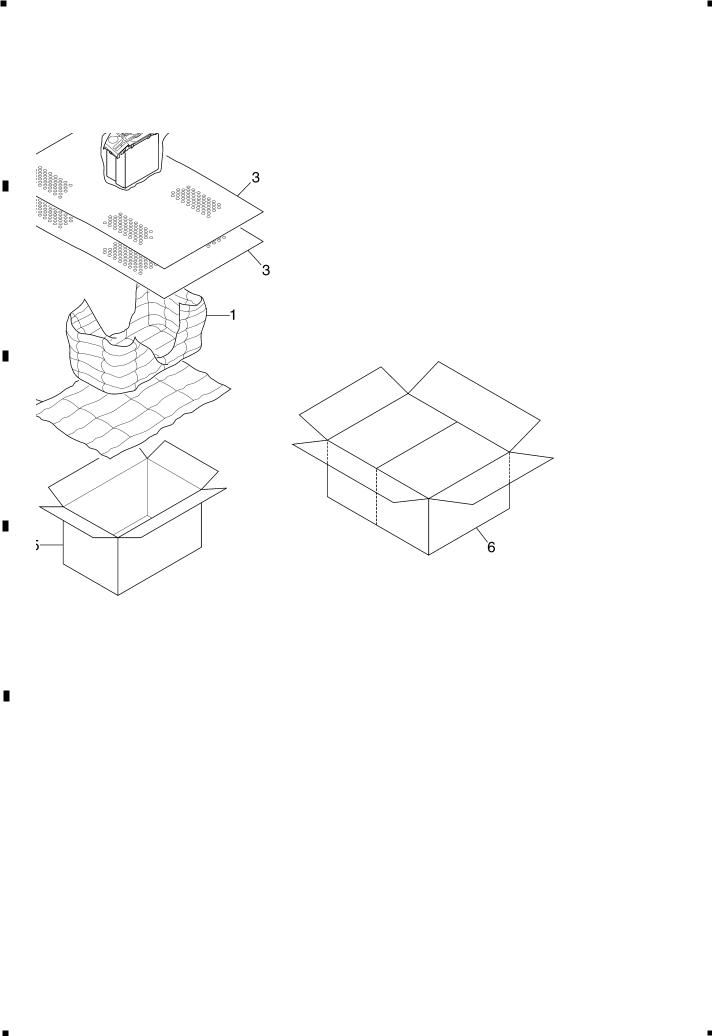
2. EXPLODED VIEWS AND PARTS LIST
2.1 PACKING(FX-M8427ZT-91/UC)
NOTE:
- Parts marked by “*” are generally unavailable because they are not in our Master Spare Parts List.
E |
- Screws adjacent to mark on the product are used for disassembly. |
|||||||
|
|
|||||||
|
|
- For the applying amount of lubricants or glue, follow the instructions in this manual. |
||||||
|
|
( In the case of no amount instructions, apply as you think it appropriate.) |
||||||
|
|
- PACKING(FX-M8427ZT-91/UC) SECTION PARTS LIST |
||||||
|
|
Mark No. Description |
Part No. |
|||||
|
|
|||||||
|
|
|||||||
|
|
|
|
|
|
|||
|
|
* |
1 Air Cap |
CHW1945 |
||||
|
|
* |
2 Air Cap |
CHW1948 |
||||
|
|
|
3 |
Cover |
CEG1045 |
|||
|
|
|
4 |
Polyethylene Bag |
CEG1174 |
|||
F |
|
5 |
Carton |
CHG4861 |
||||
|
|
|
|
|
|
|
||
|
|
|
6 |
Contain Box |
CHL4861 |
|||
|
|
6 |
|
|
|
|
|
|
|
|
|
|
|
FX-M8427ZT/UC |
|
||
|
|
|
|
|
|
|
|
|
1 |
|
2 |
|
3 |
|
4 |
|
|
|
||||
|
|
|

5 |
|
6 |
|
7 |
|
8 |
|
|
|
A
B
C
D
E
F
FX-M8427ZT/UC |
7 |
|
|
5 |
|
6 |
|
7 |
|
8 |
|
|
|
||||
|
|
|
1 |
|
2 |
|
3 |
|
4 |
|
|
|
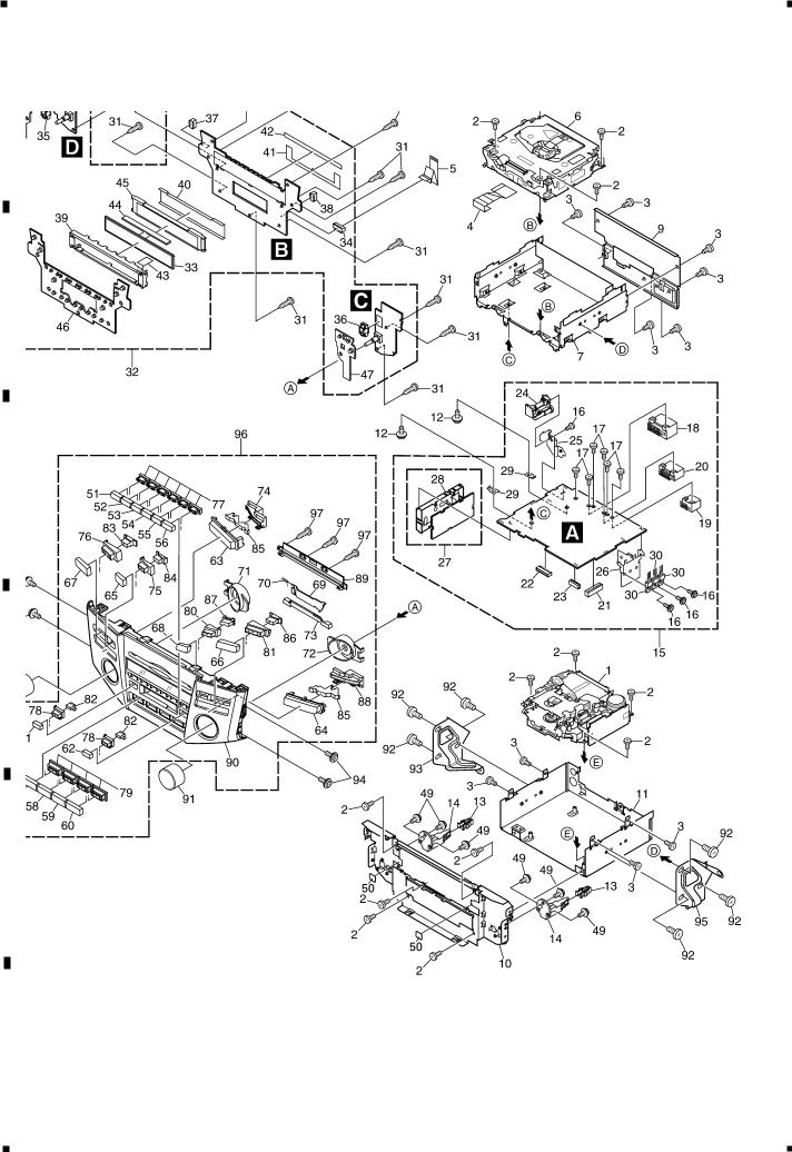
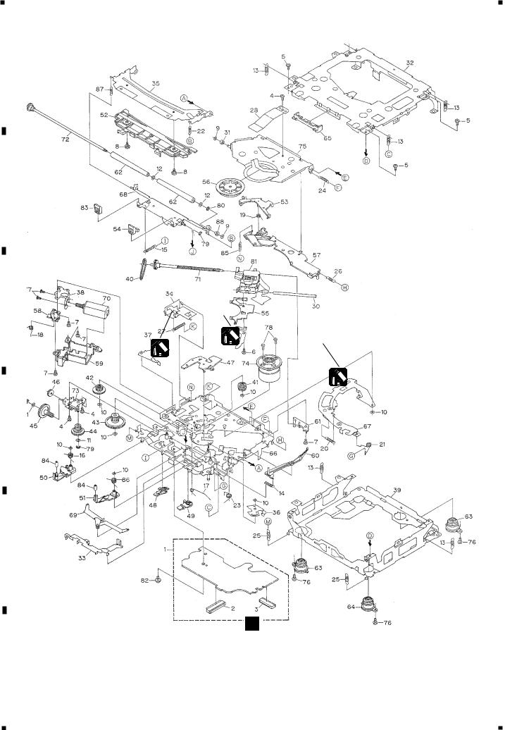
2.2 EXTERIOR
A
B
C
D
E
F
8 |
FX-M8427ZT/UC |
|
|
1 |
|
2 |
|
3 |
|
4 |
|
|
|
||||
|
|
|

5 |
|
6 |
|
7 |
|
8 |
|
|
|
- EXTERIOR SECTION PARTS LIST
Mark No. Description |
Part No. |
Mark No. Description |
Part No. |
|||
|
|
|
|
|
|
|
1 |
Cassette Mechanism Module EXK4295 |
51 |
Button(1) |
CAC7599 |
||
2 |
Screw |
BSZ26P060FTC |
52 |
Button(2) |
CAC7600 |
|
3 |
Screw |
BSZ30P060FTC |
53 |
Button(3) |
CAC7601 |
|
4 |
Connector |
CDE7248 |
54 |
Button(4) |
CAC7602 |
|
5 |
Connector |
CDE7260 |
55 |
Button(5) |
CAC7603 |
|
6 |
CD Mechanism Module(S9T)CXK5521 |
56 |
Button(6) |
CAC7604 |
||
7 |
Chassis |
CNA2466 |
57 |
Button(AM) |
CAC7605 |
|
8 |
Case |
CNB2880 |
58 |
Button(FM) |
CAC7606 |
|
9 |
Holder |
CND1792 |
59 |
Button(TAPE) |
CAC7607 |
|
10 |
Frame |
CND1789 |
60 |
Button(DISC) |
CAC7608 |
|
11 |
Chassis Unit |
CXC1820 |
61 |
Button(TAPE EJECT) |
CAC7609 |
|
12 |
Screw |
ISS26P060FTC |
62 |
Button(TEXT) |
CAC7610 |
|
13 |
90467-10203 |
CNV5641 |
63 |
Button(SEEK,TRACK) |
CAC7611 |
|
14 |
Guide |
CNV7306 |
64 |
Button(RDS,TRAF) |
CAC7612 |
|
15 |
Main Unit |
CWM8384 |
65 |
Button(CD EJECT) |
CAC7613 |
|
16 |
Screw |
BMZ30P060FTC |
66 |
Button(TYPE) |
CAC7615 |
|
17 |
Screw(M3x6) |
CBA1393 |
67 |
Button(SCAN) |
CAC7616 |
|
18 |
Connector(CN801) |
CKM1322 |
68 |
Button(MUTE) |
CAC7637 |
|
19 |
Connector(CN473) |
CKM1350 |
69 |
Door |
CAT2351 |
|
20 |
Connector(CN472) |
CKM1351 |
70 |
Spring |
CBH2663 |
|
21 |
Connector(CN353) |
CKS3568 |
71 |
Lighting Conductor |
CNV7251 |
|
22 |
Connector(CN351) |
CKS3835 |
72 |
Lighting Conductor |
CNV7252 |
|
23 |
Connector(CN804) |
CKS4361 |
73 |
Lighting Conductor |
CNV7253 |
|
24 |
Connector(CN501) |
CKX1064 |
74 |
Holder |
CNV7256 |
|
25 |
Holder |
CNC9591 |
75 |
Holder |
CNV7257 |
|
26 |
Holder |
CND1588 |
76 |
Holder |
CNV7258 |
|
27 |
FM/AM Tuner Unit |
CWE1630 |
77 |
Holder |
CNV7259 |
|
28 |
Holder |
CNC8855 |
78 |
Holder |
CNV7260 |
|
29 |
Terminal(CN802,CN803) |
VNF1084 |
79 |
Holder |
CNV7261 |
|
30 |
Transistor(Q809,811,812) |
2SB1185 |
80 |
Holder |
CNV7316 |
|
31 |
Screw |
BPZ20P080FTC |
81 |
Holder |
CNV7317 |
|
32 |
Keyboard Unit |
CWS1364 |
82 |
Lighting Conductor |
CNV7319 |
|
33 |
LCD |
CAW1722 |
83 |
Lighting Conductor |
CNV7320 |
|
34 |
Connector(CN901) |
CKS4361 |
84 |
Lighting Conductor |
CNV7321 |
|
35 |
Connector(CN904) |
CKS4591 |
85 |
Lighting Conductor |
CNV7330 |
|
36 |
Connector(CN905) |
CKS4591 |
86 |
Lighting Conductor |
CNV7467 |
|
37 |
Connector(CN902) |
CKS4592 |
87 |
Lighting Conductor |
CNV7469 |
|
38 |
Connector(CN903) |
CKS4592 |
88 |
Holder |
CNV7472 |
|
39 |
Holder |
CND1788 |
89 |
Holder Unit |
CXB8886 |
|
40 |
Sheet |
CNM7958 |
90 |
Grille Unit |
CXB9134 |
|
41 |
Seal |
CNM7970 |
91 |
Knob Unit |
CXB9458 |
|
42 |
Seal |
CNM7971 |
92 |
Screw |
BMZ50P080FTC |
|
43 |
Seal |
CNM8261 |
|
|
(FX-M8427ZT/UC) |
|
44 |
Connector |
CNV7249 |
93 |
86211-48030-A |
CND1247 |
|
45 |
Lighting Conductor |
CNV7250 |
|
|
(FX-M8427ZT/UC) |
|
46 |
Rubber |
CNV7323 |
94 |
Screw |
IMS26P060FTC |
|
47 |
Rubber |
CNV7324 |
95 |
86212-48030-A |
CND1248 |
|
48 |
Rubber |
CNV7325 |
|
|
(FX-M8427ZT/UC) |
|
49 |
Screw |
IMS26P060FTC |
96 |
Grille Assy |
CXC2064 |
|
50 |
Sheet |
CNM8435 |
97 |
Screw |
BPZ20P080FTC |
|
FX-M8427ZT/UC |
9 |
|
|
A
B
C
D
E
F
5 |
|
6 |
|
7 |
|
8 |
|
|
|
||||
|
|
|
1 |
|
2 |
|
3 |
|
4 |
|
|
|
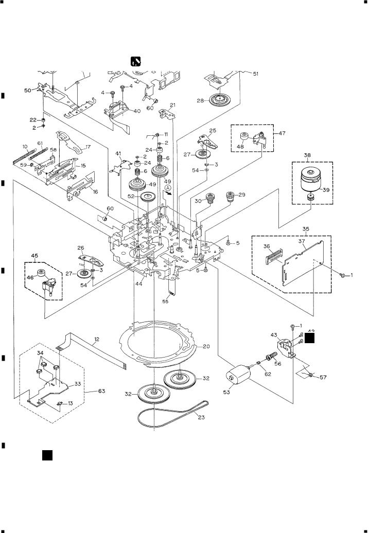
A 2.3 CD MECHANISM MODULE
B
C
UD321BR
GEM1035
GEM1035
D
E
CE
F
10 |
FX-M8427ZT/UC |
|
|
1 |
|
2 |
|
3 |
|
4 |
|
|
|
||||
|
|
|
5 |
|
6 |
|
7 |
|
8 |
|
|
|
- CD MECHANISM MODULE SECTION PARTS LIST
Mark No. Description |
Part No. |
Mark No. Description |
Part No. |
|||
1 |
Control Unit |
CWX2608 |
|
46 |
Gear |
CNV6320 |
2 |
Connector(CN701) |
CKS1959 |
47 |
Arm |
CNV6322 |
|
3 |
Connector(CN101) |
CKS3486 |
48 |
Arm |
CNV6323 |
|
4 |
Screw |
BMZ20P025FMC |
49 |
Arm |
CNV6324 |
|
5 |
Screw |
BSZ20P040FMC |
50 |
Arm |
CNV6888 |
|
6 |
Screw(M2x4) |
CBA1362 |
51 |
Arm |
CNV6889 |
|
7 |
Screw(M2x3) |
CBA1527 |
52 |
Guide |
CNV6327 |
|
8 |
Screw |
CBA1545 |
53 |
Arm |
CNV6924 |
|
9 |
Washer |
CBF1037 |
54 |
Guide |
CNV6921 |
|
10 |
Washer |
CBF1038 |
55 |
Rack |
CNV6923 |
|
11 |
Washer |
CBF1039 |
56 |
Clamper |
CNV6331 |
|
12 |
Washer |
CBF1060 |
57 |
Arm |
CNV6332 |
|
13 |
Spring |
CBH2378 |
58 |
Guide |
CNV6333 |
|
14 |
Spring |
CBH2379 |
59 |
Cover |
CNV6334 |
|
15 |
Spring |
CBH2514 |
60 |
Arm |
CNV6335 |
|
16 |
Spring |
CBH2533 |
61 |
Guide |
CNV6336 |
|
17 |
Spring |
CBH2382 |
62 |
Roller |
CNV6338 |
|
18 |
Spring |
CBH2383 |
63 |
Damper |
CNV6175 |
|
19 |
Spring |
CBH2384 |
64 |
Damper |
CNV6662 |
|
20 |
Spring |
CBH2527 |
65 |
Guide |
CNV6925 |
|
21 |
Spring |
CBH2386 |
66 |
Chassis Unit |
CXB7980 |
|
22 |
Spring |
CBH2537 |
|
* 67 Arm Unit |
CXB7983 |
|
23 |
Spring |
CBH2390 |
68 |
Arm Unit |
CXB7984 |
|
24 |
Spring |
CBH2391 |
69 |
Arm Unit |
CXB7985 |
|
25 |
Spring |
CBH2523 |
70 |
Motor Unit(M2) |
CXB8284 |
|
26 |
Spring |
CBH2426 |
71 |
Screw Unit |
CXB5904 |
|
27 |
Spring |
CBH2444 |
72 |
Gear Unit |
CXB8076 |
|
28 |
Spring |
CBL1561 |
73 |
Bracket Unit |
CXB7982 |
|
29 |
Spring |
CBL1553 |
74 |
Motor Unit(M1) |
CXB6007 |
|
30 |
Shaft |
CLA3845 |
75 |
Arm Unit |
CXB8504 |
|
31 |
Roller |
CLA3910 |
76 |
Screw(M2x5) |
EBA1028 |
|
32 |
Frame |
CNC9654 |
77 |
Screw |
JFZ20P020FMC |
|
33 |
Lever |
CNC9664 |
78 |
Screw |
JGZ17P020FZK |
|
34 |
Lever |
CNC8949 |
79 |
Washer |
YE15FUC |
|
35 |
Arm |
CNC9661 |
80 |
Washer |
YE20FUC |
|
36 |
Arm |
CNC9016 |
81 |
Pickup Unit(Service)(P9) |
CXX1482 |
|
37 |
Arm |
CNC9017 |
82 |
Screw |
IMS26P030FMC |
|
38 |
Bracket |
CNC9123 |
83 |
Guide |
CNV6922 |
|
39 |
Frame |
CNC8947 |
84 |
Roller |
CNV6887 |
|
40 |
Belt |
CNT1086 |
85 |
Spring |
CBH2509 |
|
41 |
Gear |
CNV6886 |
86 |
Spring |
CBH2512 |
|
42 |
Gear |
CNV6316 |
87 |
Spring |
CBH2536 |
|
43 |
Gear |
CNV6317 |
88 |
Collar |
CNV6906 |
|
44 |
Gear |
CNV6318 |
|
|
|
|
45 |
Gear |
CNV6319 |
|
|
|
|
FX-M8427ZT/UC |
11 |
|
|
A
B
C
D
E
F
5 |
|
6 |
|
7 |
|
8 |
|
|
|
||||
|
|
|
1 |
|
2 |
|
3 |
|
4 |
|
|
|
A 2.4 CASSETTE MECHANISM MODULE
For grease application, refer to the service manual for CX-1011 (CRT2406).
B
C
D
FD
E
GE
F
12 |
FX-M8427ZT/UC |
|
|
1 |
|
2 |
|
3 |
|
4 |
|
|
|
||||
|
|
|

5 |
|
6 |
|
7 |
|
8 |
|
|
|
- CASSETTE MECHANISM MODULE SECTION PARTS LIST
|
Mark No. Description |
Part No. |
|
Mark No. Description |
Part No. |
|
||
|
|
|
|
|
|
|
|
|
1 |
Screw |
BSZ20P040FMC |
46 |
Pinch Roller |
ENV1518 |
|
||
2 |
Washer |
CBF1037 |
47 |
Pinch Holder Unit |
EXA1607 |
|
||
3 |
Washer |
CBG1003 |
48 |
Pinch Roller |
ENV1518 |
|
||
4 |
Screw |
EBA1028 |
49 |
Reel Unit |
EXA1625 |
|
||
5 |
Screw |
CBA1037 |
50 |
Head Base Unit |
EXA1611 |
|
||
6 |
Spring |
EBH1653 |
51 |
Lever Unit |
EXA1587 |
|
||
7 |
Spring |
EBH1642 |
52 |
Gear Unit |
EXA1596 |
|
||
8 |
Spring |
EBH1641 |
53 |
Motor Unit(M2) |
EXA1623 |
|
||
9 |
Spring |
EBH1626 |
54 |
Washer |
HBF-179 |
|
||
10 |
Spring |
EBH1627 |
55 |
Spring |
EBH1537 |
|
||
11 |
Spring |
EBH1648 |
56 |
Worm Gear |
ENV1564 |
|
||
12 |
Cord |
EDD1024 |
57 |
Spring |
EBH1655 |
|
||
13 |
Photo-reflector(Q101) |
EGN1004 |
58 |
Lever |
ENC1548 |
|
||
14 |
Arm |
ENC1526 |
59 |
Washer |
YE15FUC |
|
||
15 |
Lever Unit |
EXA1610 |
60 |
Tube |
ENM1039 |
|
||
16 |
Lever |
ENC1543 |
61 |
Spring |
EBH1645 |
|
||
17 |
Arm |
ENC1532 |
62 |
Spring |
EBH1545 |
|
||
18 |
Frame |
ENC1533 |
63 |
Sensor Unit |
EWM1041 |
|
||
19 |
Holder |
ENC1547 |
|
|
|
|
|
|
20 |
Gear |
ENC1535 |
|
|
|
|
|
|
21 |
Arm |
ENC1550 |
|
|
|
|
|
|
22 |
Roller |
ENR1040 |
|
|
|
|
|
|
23 |
Belt |
ENT1027 |
|
|
|
|
|
|
24 |
Collar |
ENV1508 |
|
|
|
|
|
|
25 |
Arm |
ENV1539 |
|
|
|
|
|
|
26 |
Arm |
ENV1540 |
|
|
|
|
|
|
27 |
Gear |
ENV1569 |
|
|
|
|
|
|
28 |
Gear |
ENV1547 |
|
|
|
|
|
|
29 |
Gear |
ENR1044 |
|
|
|
|
|
|
30 |
Worm Wheel |
ENV1559 |
|
|
|
|
|
|
31 |
Lever |
ENV1551 |
|
|
|
|
|
|
32 |
Flywheel |
ENV1554 |
|
|
|
|
|
|
33 |
Gathering PCB |
ENX1073 |
|
|
|
|
|
|
34 |
Switch(S101,S102,S103) |
ESG1007 |
|
|
|
|
|
|
35 |
Deck Unit |
EWM1043 |
|
|
|
|
|
|
36 |
Plug(CN251) |
CKS3540 |
|
|
|
|
|
|
37 |
Gathering PCB |
ENX1076 |
|
|
|
|
|
|
38 |
Motor Unit(M1) |
EXA1618 |
|
|
|
|
|
|
39 |
Motor |
EXM1035 |
|
|
|
|
|
|
40 |
Head Assy(HD1) |
EXA1594 |
|
|
|
|
|
|
41 |
Arm |
ENC1537 |
|
|
|
|
|
|
42 |
Screw |
JGZ20P025FNI |
|
|
|
|
|
|
43 |
Bracket |
ENC1559 |
|
|
|
|
|
|
44 |
Chassis Unit |
EXA1636 |
|
|
|
|
|
|
45 |
Pinch Holder Unit |
EXA1608 |
|
|
|
|
|
|
|
|
|
|
|
|
|
|
|
FX-M8427ZT/UC |
13 |
|
|
A
B
C
D
E
F
5 |
|
6 |
|
7 |
|
8 |
|
|
|
||||
|
|
|
1 |
|
2 |
|
3 |
|
4 |
|
|
|
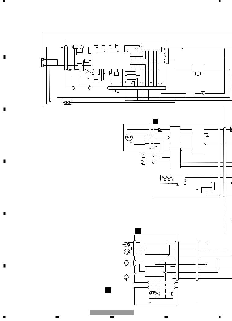
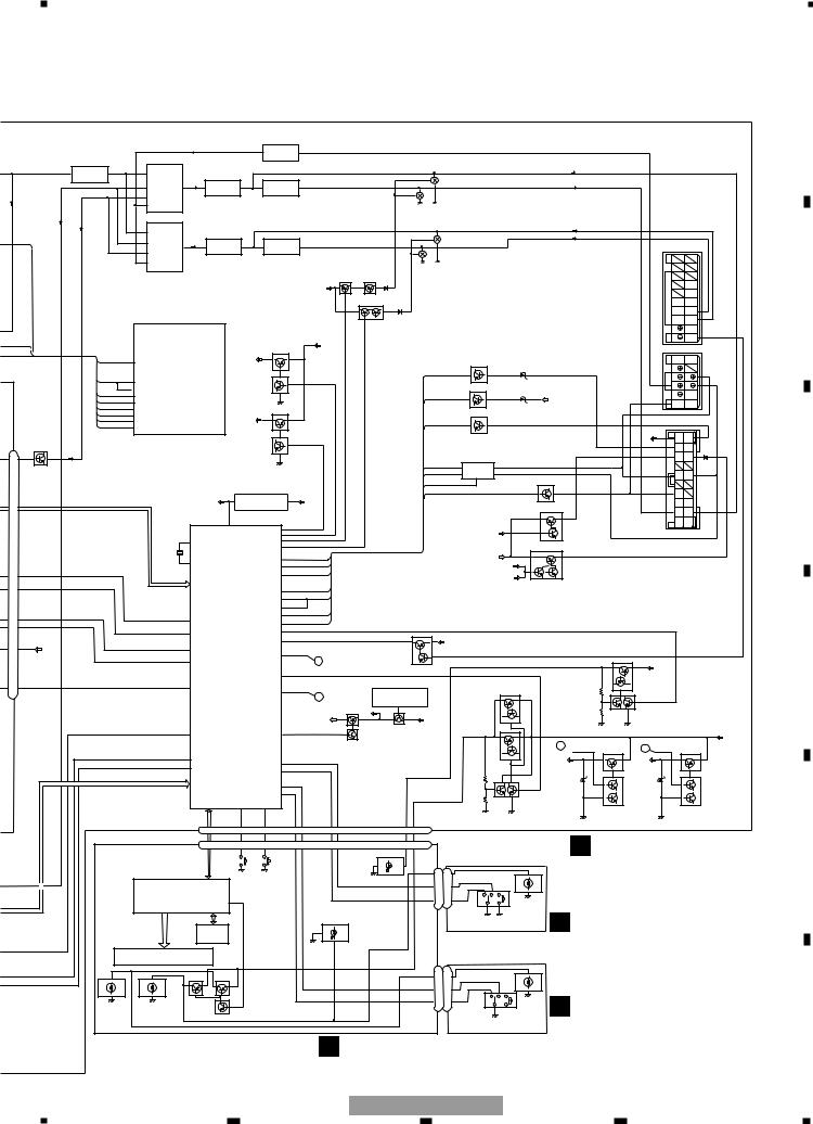
3. BLOCK DIAGRAM AND SCHEMATIC DIAGRAM
3.1 BLOCK DIAGRAM
A
FM/AM TUNER UNIT
|
|
FM/AM 1ST IF 10.7MHz |
MPXREF 41kHz |
|
|
|
|
|
|
||
|
|
AMRF |
T51 Q51 CF51 CF52 CF53 |
AMDET |
|
|
|
|
|
|
|
|
AMANT |
|
|
|
|
|
|
|
|
|
|
|
ATT |
|
|
|
|
|
|
|
|
|
|
|
28 |
|
|
IC 2 FM MPX |
L ch |
6 |
|
|
|
TUNL |
|
|
|
|
|
|
|
|
|
|
|
||
|
|
|
|
|
|
R ch |
5 |
|
|
|
|
|
|
|
|
|
|
|
|
|
|
|
|
|
|
|
|
|
|
AMIN |
20 |
|
|
|
|
CN501 |
|
|
|
|
|
|
|
|
|
|
|
|
ANT ADJ |
|
IC1 |
|
COMP 21 |
|
|
|
|
||
MAIN ANTENNA |
|
|
|
|
|
|
|
||||
|
|
|
MIXER, IF AMP, DET. |
|
LDET |
|
|
|
|
|
|
|
|
|
|
|
18 |
|
|
|
|
||
SUB ANTENNA |
FMANT |
ATT |
|
|
|
|
|
|
|
|
|
27 |
|
|
|
|
|
|
|
|
|
||
|
26 RFGND |
FMRF |
|
|
|
|
20 |
|
IC252 |
5 |
RDT |
|
|
|
|
CF202 |
|
|
RBDS |
PM4009A |
|
|
|
|
|
|
|
|
|
|
|
|
|
||
|
|
|
|
|
|
|
DECODER |
11 |
12 |
|
|
|
|
|
|
|
|
|
|
|
|
||
|
|
|
IMG ADJ |
AM 2ND IF X901 |
IC 3 |
|
|
|
X251 |
|
|
|
|
|
EEPROM |
|
|
|
|
|
|||
|
|
|
|
450kHz 10.25MHz |
|
|
|
|
|
|
|
B
C
D
RF ADJ
|
|
LOCH |
LOCL |
|
|
23 |
25 |
|
MFIX |
FMSD |
|
|
13 |
Q501 |
|
5 |
SUB IC 501 NIN 1 |
COMP |
|
6 |
LA1061M |
|
|
MAIN
DIVERSITY
WC AMPNS |
VCC |
VDD |
CREQ |
DI/DO |
FMLOCL |
DGND |
CE2 |
CK |
CE1 |
SDBW |
|
SL |
FMSD |
NL1 |
NL2 |
STIND |
AMDET |
|
|
|
|
|
|
|
|
|
|
|
|
|
7 |
17 |
22 |
10 |
19 |
14 |
24 |
11 |
12 |
15 |
16 |
|
8 |
13 |
2 |
3 |
4 |
1 |
9 |
|
|
|
|
|
|
|
|
|
|
|
|
AUDIO+B |
|
|
|
|
|
|
|
|
|
|
|
|
|
|
|
|
|
|
|
|
AM NOISE CANCELER Q561 |
|
|
|
|
|||||
|
SWVDD |
|
|
|
|
|
|
|
|
|
|
|
|
|
|
|
|
|
|
|
3 |
IC561 |
9 |
|
AM |
|
|
|
|
|
|
|
|
|
|
|
|
|
|
|
|
|
|
|
|
|
|
|
|
|
|
|
|
HA12181FP |
|
|
|
|
|
|
|
|
|
|
|
|
|
|
|
|
|
|
|
|
|
|
|
|
|
|
|
|
|
|
|
|
|
|
|
|
|
FMSD |
|
|
|
|
|
PU UNIT |
|
|
|
|
|
|
EC CONTROL UNIT |
|
|
|
|
|
|
|
|
||||||||||
|
|
|
|
|
SERVICE(P9) |
|
|
|
|
|
|
|
|
|
|
|
CN351 |
|||||||||||||
|
|
|
|
|
|
|
|
|
|
|
|
|
|
|
|
CN101 Q101 |
|
|
|
|
|
|
|
|
CN701 |
|
||||
|
|
|
|
|
LASER |
|
|
|
|
|
|
|
|
|
|
|
|
|
|
|
|
|
|
Q351 |
||||||
|
|
|
|
|
|
DIODE |
|
|
|
|
|
LD- |
|
15 |
|
|
|
9 LDO |
|
24 |
38 RFI |
|
LO 85 |
|
L-OUT 14 |
14 |
||||
|
|
|
|
|
|
|
|
|
|
|
|
|
MD |
|
|
|
|
|
|
RFRPIN |
16 |
43 FEI |
|
|
|
|
|
|
||
|
|
|
|
|
|
|
|
|
|
|
|
|
|
5 |
|
|
|
8 MDI |
FEO |
|
78 |
|
|
|
|
|||||
|
|
|
|
|
|
|
HOLOGRAM |
|
|
|
|
|
|
AC,BD |
|
|
TEO |
14 |
46 |
TEI |
|
79 |
|
|
|
|
||||
|
|
|
|
|
|
|
|
UNIT |
|
|
|
|
|
|
|
|
F,E |
|
RF-AMP |
|
|
SERVO |
|
|
|
|
||||
|
|
|
|
|
|
|
|
|
|
|
|
FO+ |
|
1 |
FOP |
|
|
|
|
|
|
CONTROL, |
|
|
|
|
||||
|
|
|
|
|
|
|
FOCUS ACT. |
|
|
|
|
|
|
|
|
|
DSP, |
|
|
|
|
|
||||||||
|
|
|
|
|
|
|
TRACKING ACT. |
TO+ |
|
4 |
TOP |
|
|
IC 101 |
|
|
LPF, DAC |
|
|
|
|
|||||||||
|
|
|
|
|
|
|
|
|
|
|
|
LD+ |
|
|
|
|
|
|
|
|
|
|
|
|
|
|
|
|||
|
|
|
|
|
MONITOR |
|
|
|
|
|
14 |
VDD |
|
TA2153FN |
|
|
|
|
|
|
|
|
|
|||||||
|
|
|
|
|
|
|
|
|
|
|
|
|
12 |
|
|
TD/FD |
|
|
|
|
|
|
|
|||||||
|
|
|
|
|
|
DIODE |
|
|
|
|
|
|
|
|
|
|
|
FOP |
|
|
|
IC 201 |
|
|
|
|
|
|||
|
|
|
|
|
|
|
|
|
|
|
|
|
|
|
|
|
|
|
14 |
TOP |
|
SD/MD |
TC9495FP |
|
|
|
|
|||
|
|
|
|
|
|
|
SPINDLE |
M |
|
|
|
|
|
|
|
|
|
|
|
|
|
|
|
|
|
|
|
|
||
|
|
|
|
|
|
|
MOTOR |
|
|
|
|
|
|
|
|
16 |
|
|
|
|
|
|
|
|
|
|
|
|||
|
|
|
|
|
|
|
|
|
|
|
|
|
|
|
|
SOP |
|
|
|
|
|
|
|
|
|
|
||||
|
|
|
|
|
|
|
|
|
|
|
|
|
|
|
|
|
|
|
|
|
|
|
|
|
|
|
|
|
||
|
|
|
|
|
|
|
|
|
|
|
|
|
|
|
|
|
|
|
15 |
SOM |
|
|
|
|
|
|
|
|
|
|
|
|
|
|
|
|
|
LOADING |
M |
|
|
|
|
|
|
|
|
17 |
LCOP |
|
|
|
|
|
|
|
LOEJ 10 |
|
|||
|
|
|
|
|
|
|
/CARRIAGE |
|
|
|
|
|
|
|
|
18 |
LCOM LOEJ |
22 |
|
|
|
|
|
10 |
||||||
|
|
|
|
|
|
|
MOTOR |
|
|
|
|
|
|
|
|
|
|
|
MUTE |
9 |
|
|
|
|
|
CONT 11 |
|
|||
|
|
|
|
|
|
|
|
|
|
|
|
|
|
|
|
|
|
|
|
|
|
|
|
|
|
11 |
||||
|
|
|
|
|
|
|
|
|
|
|
|
|
|
|
|
|
|
ACT |
|
IC 401 |
|
|
|
|
|
|
|
|
|
|
|
|
|
|
|
|
|
|
|
|
|
|
|
|
|
|
|
|
|
|
|
|
|
|
|
|
|
|
|
||
|
|
|
|
|
|
|
|
|
|
|
|
|
|
|
|
|
/MOTOR DRIVER BA5996FM |
|
|
|
|
|
|
|
|
|
||||
|
|
|
|
|
|
|
|
|
|
|
|
|
|
|
|
|
|
|
|
|
|
|
|
|
|
|
DSCSNS 17 |
17 |
||
|
|
|
|
|
|
|
|
|
|
|
|
|
|
|
|
|
|
|
|
|
|
|
|
|
|
|
|
HOME 16 |
11 |
|
|
|
|
|
|
|
|
|
|
|
|
|
|
|
|
|
|
|
|
|
|
S901 |
|
|
|
|
|
|
|
|
|
|
|
|
|
|
|
|
|
|
|
|
|
|
|
|
|
|
|
|
|
|
HOME |
|
|
|
VD |
VD |
2 |
2 |
||
|
|
|
|
|
|
|
|
|
|
|
|
|
|
|
|
|
|
|
|
|
|
|
|
|
|
|||||
|
|
|
|
|
|
|
|
|
|
|
|
|
|
|
|
|
|
12EJ |
DISC |
|
|
|
|
5V REGULATOR |
|
C |
||||
|
|
|
|
|
|
|
|
|
|
|
|
|
|
|
|
|
|
SENSE |
SENSE |
|
|
|
|
|
||||||
|
|
|
|
|
|
|
|
|
|
|
|
|
|
|
|
|
CLAMP |
8EJ |
|
|
|
|
4 |
IC 701 |
|
2 |
|
|
||
|
|
|
|
|
|
|
|
|
|
|
|
|
|
|
|
|
SENSE |
SENSE |
|
|
|
VDD |
|
|
|
|||||
|
|
|
|
|
|
|
|
|
|
|
|
|
|
|
|
|
|
|
|
|
|
|
|
|
|
BA05SFP |
|
|
|
|
|
|
|
|
|
|
|
|
|
|
|
|
|
|
|
|
|
|
|
|
|
|
|
|
|
|
1 |
CD5VON |
1 |
1 |
|
|
|
|
|
F DECK UNIT |
|
|
|
|
|
|
|||
E |
|
|
|
CN252 |
|
|
|
|
|
CN251 |
|
|
CN353 |
|
|
1 |
|
|
|
|
|
|
4 |
|
|
||
|
FWD |
|
|
|
EQ AMP |
16 |
TAPE+B |
4 |
AUDIO+B |
||||
|
|
|
|
|
|
|
|
||||||
|
L-ch |
|
|
37 |
|
|
|
|
|
|
|
|
|
|
|
|
|
|
IC251 |
|
|
|
|
|
|
||
|
|
|
5 |
38 |
|
|
|
6 |
3 |
3 |
CSL |
||
|
REV |
|
39 |
|
HA12216F |
|
Lch |
|
|||||
|
|
|
|
|
|
|
|
||||||
|
L-ch |
|
4 |
|
|
|
|
|
|
|
|
|
|
|
|
|
|
|
12 |
10 |
|
|
|
|
|
||
|
|
|
|
|
|
|
|
|
|
|
|
||
|
M2 |
|
|
CN254 |
|
|
|
|
|
MUTE |
9 |
|
|
|
M |
2 |
MECHANISM |
|
|
|
|
|
|
|
|||
|
SUB |
|
|
|
B.U 20 |
|
|
||||||
|
MOTOR |
1 |
DRIVER18 |
|
19 |
|
20 |
BU |
|||||
|
|
|
|
|
|
|
|
|
|
||||
|
|
|
|
5 |
|
IC351 |
|
|
17 |
STBY 19 |
19 |
|
|
|
|
|
|
2 |
|
|
|
|
|
|
|
|
|
|
|
|
|
1 |
PA2020A |
|
|
MTL |
|
|
|
||
|
M1 |
|
|
CN255 |
|
|
|
|
|
8 |
8 |
|
|
|
MAIN |
M |
|
|
7 |
10 |
|
|
LOAD |
|
|||
|
|
8 |
|
|
|
11 |
11 |
|
|||||
|
MOTOR |
|
|
CN253 |
|
|
|
|
|
|
|
|
|
|
|
|
|
3 |
1 |
5 |
|
4 |
6 |
|
|
|
|
|
|
|
|
|
|
|
|
|
|||||
|
G SENSOR UNIT |
|
CN256 |
3 |
1 |
5 |
|
4 |
6 |
|
|
|
|
F |
|
|
|
|
|
|
|
|
|
|
|||
|
Q101 |
|
|
|
|
|
|
|
|
|
|||
|
|
|
|
REEL |
|
|
|
|
|
|
|
|
|
|
|
|
|
SENSE |
|
|
|
|
|
|
|
|
|
|
|
|
|
|
|
|
S102 |
S103 |
S101 |
|
|
|
|
|
|
|
|
|
|
|
MODE |
70 s |
LOAD |
|
|
|
|
14 |
FX-M8427ZT/UC |
|
|
|
|
|
|
|
|
|
|
|
|
1 |
2 |
|
|
3 |
|
|
|
|
|
|
|
4 |
|
5 |
|
6 |
|
7 |
|
8 |
|
|
|
A
|
|
|
|
|
|
|
|
|
BALANCE TO UNBALANCE CONVERTER |
|
|
|
|
|
|
|
|
||||
|
|
|
|
|
LANL |
|
|
|
|
|
7 |
IC201 |
5 |
|
|
|
|
|
|
|
|
|
|
TUNER |
|
|
|
SELECTOR |
|
|
|
|
|
NJM2068MD |
|
|
|
|
|
|
|
|
|
|
|
MIXING AMP |
|
|
|
|
|
|
|
|
|
|
|
|
|
|
|
|
|
||
|
2 |
|
|
|
|
|
|
|
|
|
|
|
|
|
|
|
|
|
|
||
TUNL |
IC401 |
1 |
|
2 |
IC202 |
|
UNBALANCE TO BALANCE CONVERTER |
|
|
|
|
|
|
|
|
||||||
|
|
NJM2068MD |
|
|
|
|
|
|
|
|
|
|
|
|
|
|
|
|
|
||
|
|
|
|
TC4052BF |
|
|
|
|
|
|
|
|
Q204 |
|
|
|
|
|
|
||
|
|
|
|
|
1 |
3 |
6 |
IC203 |
7 |
6 |
IC204 |
7 |
|
|
|
|
|
|
|
||
|
|
|
|
|
|
|
|
|
|
|
|
|
|
||||||||
|
CSL |
|
|
|
4 |
|
|
|
NJM2068MD |
|
|
NJM2068MD |
|
|
|
|
|
|
|
|
|
|
|
|
|
|
|
|
|
|
|
|
|
|
|
|
|
|
|
|
|
|
|
|
|
CDL |
|
|
5 |
|
|
|
|
|
|
|
|
Q205 |
|
|
|
|
|
|
|
|
|
|
|
|
|
|
|
|
|
|
|
|
|
|
|
|
|
|
|
|
|
|
|
|
|
|
|
SELECTOR |
|
|
|
|
|
|
|
|
|
|
|
|
|
|
|
|
|
|
|
|
2 |
IC302 |
|
UNBALANCE TO BALANCE CONVERTER |
|
|
|
|
|
|
|
|
|||||
|
|
|
|
|
|
|
|
|
|
|
|
|
|
|
|
|
|
|
|
||
|
|
|
|
|
|
|
|
|
|
|
|
|
|
|
|
|
|
|
|
|
|
RDT |
|
|
|
|
1 |
TC4052BF |
3 |
6 |
IC303 |
7 |
6 |
IC304 |
7 |
|
Q304 |
|
|
|
CN472 |
|
|
|
|
|
|
|
4 |
|
|
|
|
|
|
|
|||||||||
|
|
|
|
|
|
|
|
NJM2068MD |
|
|
NJM2068MD |
|
|
|
|
|
|
|
|
|
|
|
|
|
|
|
5 |
|
|
|
|
|
|
|
|
|
|
|
|
|
|
|
|
|
|
|
|
|
|
|
|
|
|
|
|
|
|
Q305 |
|
|
|
|
|
|
|
|
|
|
|
|
|
|
|
|
|
|
|
|
Q864 |
Q866 |
|
|
|
|
|
SLD2 |
|
|
|
|
|
|
|
|
|
|
|
|
|
|
SWVDD |
|
|
|
|
|
|
|
|
|
|
|
|
|
|
|
|
|
|
|
|
|
|
|
|
|
|
|
|
B |
|
|
|
|
|
|
|
|
|
|
|
|
|
|
|
|
|
|
|
|
|
RSR+ |
|
|
|
|
|
|
|
|
|
|
|
|
|
|
|
Q865 Q867 |
|
|
|
|
GND2 |
RSR- |
|
|
|
|
|
|
|
|
|
|
|
|
|
|
|
|
|
|
|
|
SW1 |
RSL+ |
|
|
|
|
|
|
|
|
|
|
|
|
|
|
|
|
|
|
|
|
SW2 |
RSL- |
|
|
|
|
|
|
|
|
|
|
|
|
|
|
|
|
|
|
|
|
TX2 |
RMU |
|
|
|
|
|
|
|
|
|
|
|
|
|
|
|
|
|
|
|
|
TX2 |
ADIM |
|
FMSD |
|
|
|
|
|
|
|
|
|
|
|
|
AUDIO+B |
|
|
|
|
|
CN473 |
|
|
|
|
|
|
|
|
|
|
|
|
|
|
Q563(1/2) |
|
|
|
|
|
|
|||
|
|
|
|
|
|
SYSTEM |
|
|
|
|
|
|
|
|
|
|
|
||||
|
|
|
|
|
|
|
|
FMB |
|
|
|
|
|
|
|
|
|
|
|
||
|
|
|
FMSD |
1 |
FMSD |
CONTROLLER |
|
|
|
|
|
|
|
ISENS |
|
SLD1 |
GND1 |
|
|||
|
|
|
|
|
|
|
|
|
|
|
|
|
|
|
|
|
|||||
|
|
|
|
|
|
IC 601(1/2) |
|
|
|
Q564(1/2) |
|
isen |
|
Q805 |
|
R |
|
|
|||
|
|
|
|
|
|
PD5772A |
|
|
|
|
|
|
|
|
R |
|
|
||||
|
|
|
|
|
|
|
|
|
|
|
|
|
|
|
TX1 |
|
|||||
|
|
|
DI/DO |
32 |
|
|
|
|
|
|
|
|
|
|
|
|
|
||||
|
|
|
PDI |
|
|
|
|
|
|
|
|
|
|
|
|
|
|
|
|
||
|
|
|
|
31 |
|
|
|
|
|
|
|
|
|
|
|
|
|
L |
TX1 |
|
|
|
|
|
|
PDO |
|
|
|
|
|
|
|
|
|
|
BSENS |
|
|
||||
|
|
|
CE2 |
11 |
|
|
|
|
|
|
|
|
|
|
|
L |
|
|
|||
|
|
|
PCE2 |
|
|
|
|
|
|
|
|
bsens |
|
Q806 |
BU |
ACC |
|
||||
|
|
|
CK |
33 |
|
|
|
|
|
|
|
|
|
|
|
|
|||||
|
|
|
pck |
|
|
|
|
|
|
|
|
|
|
|
|
MUTE |
+B |
|
|||
|
|
|
CE1 |
34 |
|
|
|
|
|
|
|
|
|
|
|
|
|
|
|||
|
|
|
PCE1 |
|
|
|
|
|
|
Q563(2/2) |
|
|
|
|
|
|
|
|
|
||
|
|
|
SL |
93 |
|
|
|
|
|
|
|
|
|
ASENS |
|
|
|
|
|||
|
|
|
SL |
|
|
|
|
|
|
|
|
|
|
|
|
|
|
||||
|
|
|
RDT |
44 |
|
|
|
|
AMB |
|
|
|
|
|
|
|
|
|
|||
|
|
|
RDT |
|
|
|
|
|
|
|
asens |
|
|
Q807 |
|
|
|
|
|||
|
|
|
ST |
2 |
ST |
|
|
|
|
|
|
|
|
|
|
|
|
|
|
|
|
|
|
|
|
|
|
|
|
|
|
|
Q564(2/2) |
|
|
|
|
|
BU |
+B |
ACC |
|
|
CN351 |
|
|
|
|
|
|
|
|
|
|
|
|
|
|
|
|
|
|
|||
|
|
|
|
|
|
|
|
|
|
|
|
|
|
|
|
|
|
|
|
||
|
|
|
|
|
|
|
|
|
|
|
|
|
|
|
|
|
|
|
|
|
|
Q351 |
|
|
|
|
|
|
|
|
|
|
|
|
|
|
|
|
|
|
ILL+ |
ILL- |
|
14 |
|
|
|
|
|
|
|
|
|
|
|
|
|
|
AVC-LAN BUS DRIVER |
|
AMP |
ANT |
|
||
|
|
|
|
|
|
|
|
|
|
|
|
|
|
TX |
1 |
IC701 |
6 |
|
|
|
|
|
|
|
|
|
|
|
|
|
|
|
|
|
|
RX |
2 HA12187FP |
5 |
|
ATX+ ATX- |
C |
||
|
|
|
|
|
|
|
|
|
|
|
|
|
|
IPPW |
|
8 |
|
MUTE |
|
|
|
|
|
|
|
|
|
|
|
|
|
RESET |
|
MUTE |
|
|
|
Q801 |
|
|
|
||
|
|
|
|
|
|
|
|
|
|
|
|
|
|
|
MUTE |
|
|
||||
|
|
|
|
|
|
|
|
|
|
|
|
|
|
|
|
|
|
|
|
||
1 |
IC 602 |
2 |
|
R+ |
R- |
RESET |
S-80835CNUA-B8U |
VDD |
AMP+B Q882 |
||
|
|
|
|
||
|
|
|
L+ |
L- |
|
|
|
|
|
||
12 |
|
|
|
SLD |
GND |
|
|
reset |
AMPW |
42 |
|
|
|
CN801 |
|
|
41 |
|
SYSPWR |
Q884 |
|||
|
15 |
|
FMPW |
52 |
|
|
|
|
|
XIN |
SYSMUTE1 |
|
|
|
|
||
|
53 |
|
|
ANT+B Q451 |
|
|||
|
X601 |
|
sysmute@ |
|
|
|
|
|
|
|
|
75 |
|
BU |
|
|
|
|
13 |
XOUT |
bsens |
|
|
|
||
|
|
asens |
73 |
|
|
AMB |
|
|
|
|
|
65 |
|
|
|
||
10 |
|
|
isen |
|
|
Q452 |
|
|
|
|
|
|
|
|
FMB |
|
|
|
|
|
|
|
|
|
Q453 |
|
11 |
|
|
TX |
30 |
|
|
|
|
|
|
|
RX1 |
29 |
RX |
|
|
|
|
|
|
21 |
|
|
|
|
|
|
|
|
RX2 |
|
|
|
|
|
|
|
|
22 |
|
|
|
|
|
|
|
|
IPPW |
|
|
|
|
|
17 |
39 |
XOUTLOEJ |
56 |
|
|
|
|
|
AMPMUTE |
|
|
|
|
||||
11 |
40 |
CONT |
BLIGHT |
28 |
|
|
|
|
|
57 |
|
|
|
|
|||
|
|
SYSTEM |
ADIM |
|
SWVDD |
|
|
|
2 |
89 |
|
Q722 |
|
|
|||
DSCSNS CONTROLLER |
|
|
|
|
|
|
|
CD8R3V |
|
|
IC 601(2/2) |
VDCNT |
63 |
|
|
|
|
|
|
|
|
|
|
|
|
|
87 |
|
|
|
A |
|
|
|
|
|
|
|
|
|
D |
|||
|
|
home |
PD5772A |
|
|
|
|
|
|
|
|
|
|
|
|
|||
|
|
|
|
|
|
|
|
|
|
Q721 |
|
|
|
|
Q818 |
BU |
||
|
|
|
|
|
|
4 |
|
|
|
|
|
|
|
|
|
|
|
|
|
|
|
|
|
LAMP |
|
|
|
|
|
|
|
|
|
|
|
|
|
1 |
|
23 |
CD5VON |
|
|
43 |
|
|
|
VDD 5V REG. |
ILLB REGULATOR |
|
|
|
|
|
|
|
|
|
|
|
|
SYSPWR |
|
|
B |
|
IC870 |
|
Q811 |
|
|
|
Q819 |
|
|
|
|
|
|
|
|
|
|
|
S-812C56AUA-C3K |
|
|
|
|
|
|
|
||
|
|
|
|
|
|
|
|
|
|
|
|
|
|
|
|
|
||
|
|
|
|
|
|
|
|
|
VDD |
3 |
|
|
|
|
Q820 |
|
|
|
|
|
|
|
|
|
|
|
|
|
|
|
|
|
|
|
|||
|
|
|
|
|
|
|
|
SWVDD |
Q645 |
|
BU |
|
|
|
|
LCDBL REGULATOR |
||
|
|
|
|
|
|
|
|
|
Q870 |
|
Q813 |
|
|
|
||||
|
|
|
|
|
|
|
|
|
|
|
|
|
|
|
|
|||
|
|
80 stby |
|
SWVDD |
55 |
|
|
Q644 |
|
|
Q812 |
|
|
|
|
|
|
|
|
|
|
|
|
|
|
|
|
|
|
|
|
BU |
|||||
|
|
|
|
|
|
|
|
|
|
|
|
|
|
|
|
|
|
|
|
|
|
|
|
|
|
|
|
|
|
|
|
A |
VDCONT |
Q809 |
B |
SYSPWR |
Q808 |
|
|
|
|
|
|
|
|
|
|
|
|
|
|
|||||
|
|
69 |
metal |
|
|
83 |
|
|
|
|
|
Q814 |
CD8R3V |
|
AUDIO+B |
|
|
|
|
|
71 |
CSLOAD |
|
ENC1- |
|
|
|
|
|
|
|
|
|
||||
|
|
|
|
ENC1+ |
82 |
|
|
|
|
|
|
|
|
|
|
|
|
|
|
|
|
|
|
|
|
|
|
|
|
|
|
|
|
|
|
||
|
|
|
|
|
ENC2- |
85 |
|
|
|
|
|
|
|
|
|
|
|
|
|
|
|
|
|
ENC2+ |
84 |
|
|
|
|
|
|
|
|
|
|
|
|
|
|
|
|
|
|
|
|
|
|
|
|
Q822 |
|
|
|
|
|
|
|
|
|
|
cdej |
csej |
|
ENC2M |
ENC1P ENC1M |
|
|
|
|
|
|
Q815 |
|
|
Q802 |
|
|
|
|
20 |
74 |
ENC2P |
|
LCDBL |
|
|
|
|
|
|
||||
|
|
|
|
|
|
|
|
|
|
|
|
|
||||||
|
|
CN804 |
|
|
|
ILLB |
|
|
CD 8.3V REGULATOR |
AUDIO +B REGULATOR |
||||||||
|
|
|
|
17 |
23 |
21 22 |
19 20 |
|
14,15 |
9-13 |
|
|
A MAIN UNIT |
|
|
|||
|
|
CN901 |
17 |
23 |
21 22 |
19 20 |
|
14,15 |
9-13 |
|
|
|
E |
|||||
|
|
|
|
CDEJ |
CSEJ |
|
|
|
|
|
1 |
1 |
|
|
|
|
|
|
|
|
IC 901 |
|
3 |
|
|
|
|
|
|
7 |
7 |
|
|
|
|
|
|
|
|
LC75804W |
4 |
|
|
|
|
|
|
|
|
|
|
|
|
|||
|
|
|
|
|
|
|
|
6 |
|
|
|
|
|
|
|
|||
|
|
KEY CONTROLLER |
1 ILLCONT |
|
|
|
|
|
|
6 |
|
|
|
|
|
|
||
|
|
LCD DRIVER |
|
|
|
|
|
|
|
|
CN904 |
D LEFT PCB |
|
|
|
|||
|
|
|
KEY |
|
|
|
|
|
|
|
CN902 |
|
|
|
||||
|
|
|
|
|
|
|
|
|
|
PWR•VOL |
|
|
|
|||||
|
|
|
|
|
|
|
|
|
|
|
VR901 |
|
|
|
|
|
|
|
|
|
|
MATRIX |
|
|
|
|
|
|
|
|
|
|
|
|
|
|
|
|
|
LCD901 |
|
|
|
|
|
|
|
|
|
|
|
|
|
|
|
|
|
|
|
Q903 |
Q901 |
|
|
|
|
|
|
1 |
1 |
|
|
|
|
|
|
|
|
|
|
|
|
|
|
|
|
|
7 |
7 |
C RIGHT PCB |
|
|
|
||
|
|
|
|
|
|
|
|
|
|
|
6 |
6 |
|
|
|
|||
|
|
|
|
Q902 |
|
|
|
|
|
|
CN903 |
CN905 |
|
|
|
|||
|
|
|
|
|
|
|
|
|
|
|
|
VR902 |
|
|
|
|
|
|
|
|
|
|
|
|
|
|
|
|
|
|
AUDIO•TUNE |
|
|
|
|
|
F |
|
|
|
|
|
|
|
|
B KEYBOARD PCB |
|
|
|
|
|
|
||||
|
|
|
|
|
|
|
|
|
|
|
|
|
|
|
||||
|
|
|
|
|
|
|
|
|
|
FX-M8427ZT/UC |
|
|
|
|
|
15 |
||
|
|
5 |
|
|
|
|
|
6 |
|
|
|
7 |
|
|
|
|
|
8 |
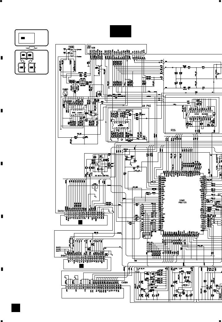
1 |
|
2 |
|
3 |
|
4 |
|
|
|
3.2 OVERALL CONNECTION DIAGRAM(GUIDE PAGE)
Note: When ordering service parts, be sure to refer to " EXPLODED VIEWS AND PARTS LIST" or "ELECTRICAL PARTS LIST".
A |
|
|
|
|
Large size |
A-a |
|
|
|
|
|
||
|
|
|
|
|
SCH diagram |
|
|
A-a |
|
A-b |
|
||
|
|
|
|
|
|
|
FM/AM TUNER UNIT FM(400Hz, 30%MOD):-24.2dBs
AM(400Hz, 30%MOD):-12.0dBs
A-a |
A-b |
Guide page |
A-a |
A-b |
Detailed page |
B
FM DIVERSITY
C
D
SYSTEM
CONTROLLER
E CN701 CD(1kHz):+4.0dBs
E
TAPE(1kHz):-7.4dBs F CN251
F |
B |
CN901 |
A
16 |
FX-M8427ZT/UC |
|
|
1 |
|
2 |
|
3 |
|
4 |
|
|
|
||||
|
|
|
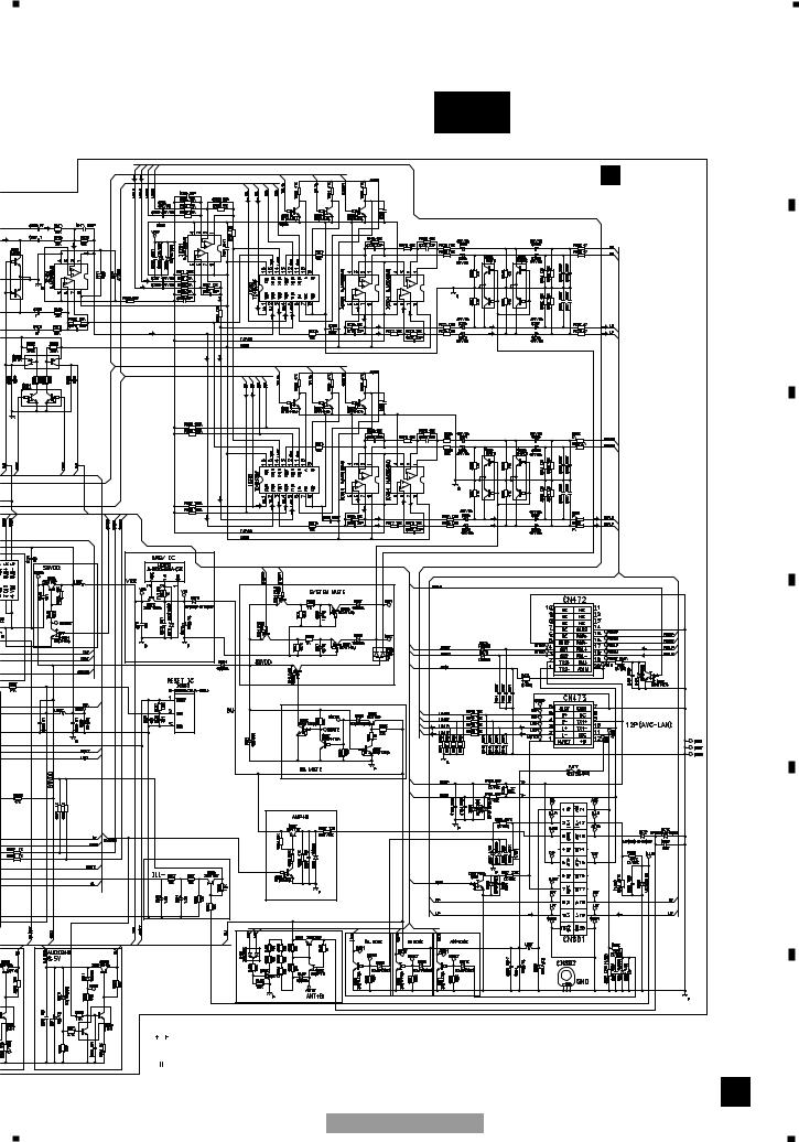
5 |
|
6 |
|
7 |
|
8 |
|
|
|
A-b
A
A MAIN UNIT
B
FM:-14.4dBs TAPE:-7.4dBs
AM:-11.4dBs CDCH:-2.2dBs
CD:-1.6dBs
C
D
CDCH(1kHz):+8.3dBs
>
E
FM:-4.6dBs
AM:-1.6dBs
CD:+8.3dBs
TAPE:+2.4dBs
CDCH:+7.8dBs
350 H
NOTE : |
|
|
||||
|
|
|
|
Symbol indicates a resistor. |
Decimal points for resistor |
|
|
|
|
||||
|
|
|
|
No differentiation is made between chip resistors and |
||
|
|
|
|
and capacitor fixed values |
||
|
|
|
|
discrete resistors. |
||
|
|
|
|
are expressed as : |
||
|
|
|
|
Symbol indicates a capacitor. |
2.2 ← |
2R2 |
|
|
|
|
|||
|
|
|
|
No differentiation is made between chip capacitors and |
0.022 |
←R022 |
|
|
|
|
discrete capacitors. |
|
|
FX-M8427ZT/UC
The > mark found on some component parts indicates the importance of the safety factor of the part. Therefore, when replacing, be sure to use parts of identical designation.
F
A
17
5 |
|
6 |
|
7 |
|
8 |
|
|
|
||||
|
|
|
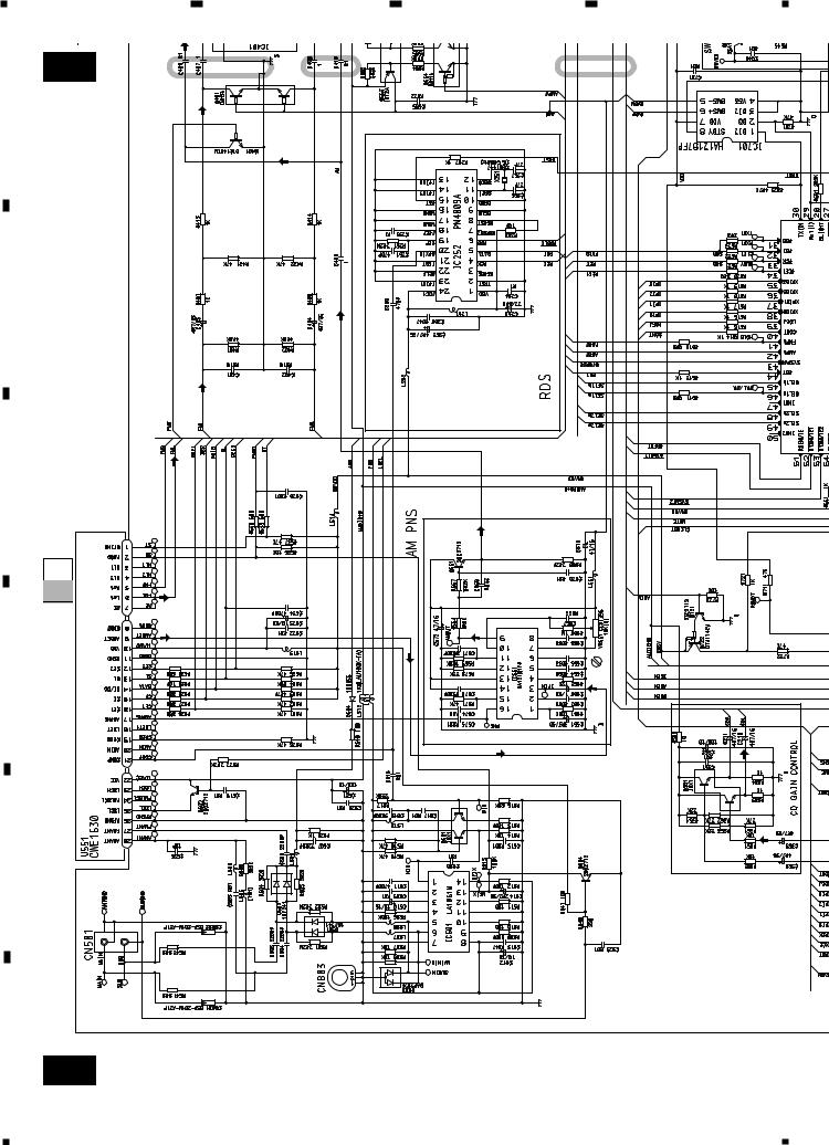
1 2 3 4
A-b |
1 |
2 |
3 |
A
B
C
D
E
A-a A-b |
30%MOD):-24.2dBs |
30%MOD):-12.0dBs |
|
FM(400Hz, |
AM(400Hz, |
|
FM/AM TUNER UNIT |
|
FM DIVERSITY
F
A-a
18 |
FX-M8427ZT/UC |
|
|
1 |
|
2 |
|
3 |
|
4 |
|
|
|
||||
|
|
|

5 6 7
4 5 6
SYSTEM |
CONTROLLER |
CD(1kHz):+4.0dBs
CN701 |
CN251 |
E |
F |
|
TAPE(1kHz):-7.4dBs |
FX-M8427ZT/UC
B CN901
8
A-b
A
B
C
A-a A-b
D
E
F
A-a
19
5 |
|
6 |
|
7 |
|
8 |
|
|
|
||||
|
|
|

A
1 2 3 4
MAIN UNIT
A
B
C
A-a A-b
D
TAPE:-7.4dBs |
CDCH:-2.2dBs |
FM:-14.4dBs |
AM:-11.4dBs CD:-1.6dBs |
E
F
A-b |
1 |
2 |
3 |
20 |
|
|
FX-M8427ZT/UC |
1 |
2 |
3 |
4 |
5 |
4 |
5
6
M8427ZT/UC-FX |
6 |
7
8
21 |
b-A |
CDCH(1kHz):+8.3dBs
>
FM:-4.6dBs
AM:-1.6dBs
CD:+8.3dBs
TAPE:+2.4dBs
CDCH:+7.8dBs
350 H
NOTE :
Symbol indicates a resistor.
No differentiation is made between chip resistors and discrete resistors.
Symbol indicates a capacitor.
No differentiation is made between chip capacitors and discrete capacitors.
Decimal points for resistor and capacitor fixed values are expressed as :
2.2 |
← |
2R2 |
||
|
||||
0.022 |
|
← |
R022 |
|
|
|
|||
A-a |
A-b |
|
|
|
The > mark found on some component parts indicates the importance of the safety factor of the part. Therefore, when replacing, be sure to use parts of identical designation.
5
6
7
8
F |
|
E |
|
D |
|
C |
|
B |
|
A |
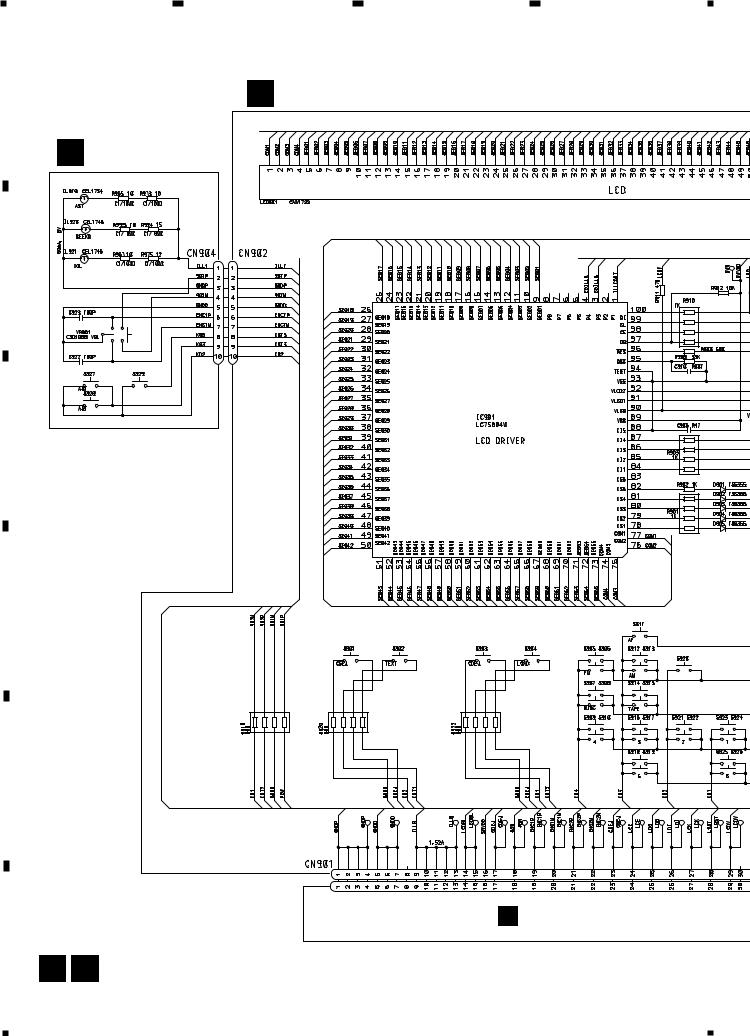
1 2 3 4
|
3.3 KEYBOARD UNIT |
A |
B KEYBOARD PCB |
|
D LEFT PCB |
B
SEEK•TRACK DOWN
C
D
SEEK•TRACK UP
E
A CN804
F
B D
22 |
FX-M8427ZT/UC |
|
|
1 |
|
2 |
|
3 |
|
4 |
|
|
|
||||
|
|
|
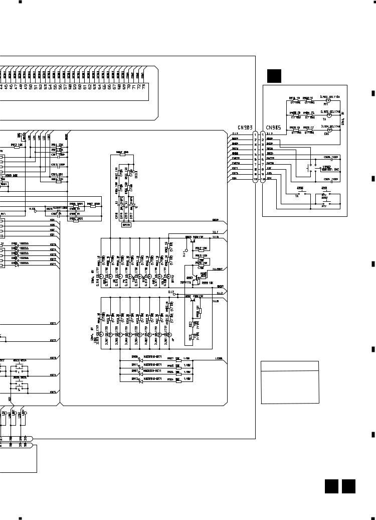
5 |
|
6 |
|
7 |
|
8 |
|
|
|
A
C RIGHT PCB
B
C
D
RACK UP
KEYBOARD UNIT
Consists of
KEYBOARD PCB
RIGHT PCB
LEFT PCB
B C
FX-M8427ZT/UC |
23 |
|
|
E
F
5 |
|
6 |
|
7 |
|
8 |
|
|
|
||||
|
|
|
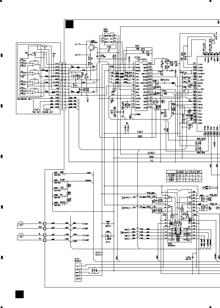
1 |
|
2 |
|
3 |
|
4 |
|
|
|
|
3.4 CD MECHANISM MODULE |
|
A |
E CONTROL UNIT |
|
|
|
|
|
PICKUP UNIT |
|
|
(SERVICE)(P9) |
RF AMP |
|
|
|
|
CN101 |
|
B |
|
91K |
|
91K |
C
D
ACT/MOTOR DRIVER
|
SPINDLE |
|
M1 CXB6007 |
E |
LOADING/CARRIAGE |
|
M2 CXB8284 |
F
5V REGULATOR
E
24 |
FX-M8427ZT/UC |
|
|
1 |
|
2 |
|
3 |
|
4 |
|
|
|
||||
|
|
|
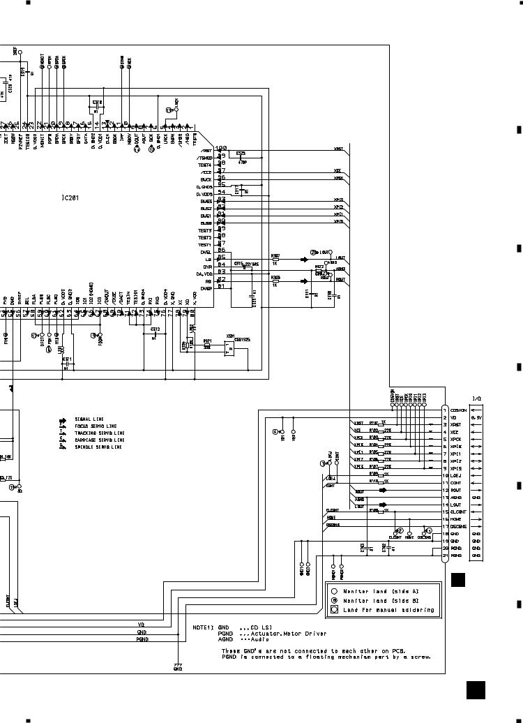
5 |
|
6 |
|
7 |
|
8 |
|
|
|
A
SERVO CONTROL/DSP/DAC/LPF
B
TC9495FP
C
16.934MHz
D
SWITCHES:
CONTROL UNIT
S901 : HOME SWITCH.....ON-OFF
S902 : CLAMP SWITCH....ON-OFF
S903 : DSCSNS SWITCH....ON-OFF
S904 : 12EJ SWITCH....ON-OFF
S905 : 8EJ SWITCH....ON-OFF
The underlined indicates the switch position.
E
CN701
A
CN351
F
E
FX-M8427ZT/UC |
25 |
|
|
5 |
|
6 |
|
7 |
|
8 |
|
|
|
||||
|
|
|
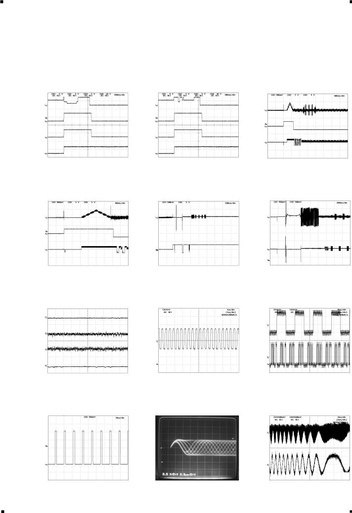
1 |
|
2 |
|
3 |
|
4 |
|
|
|
Note:1. The encircled numbers denote measuring pointes in the circuit diagram.
2.Reference voltage VREF:2.1V
A |
- Waveforms |
|
|
|
|
|
|
|
|
|
|
|
|
|
|
|
|
|
|
||||||
|
|
|
|
|
|
|
|
|
|
|
|
|
|
|
|
|
|
|
|
|
|
|
|
||
|
|
|
|
|
|
|
|
|
|
|
|
|
|
|
|
|
|
|
|
|
|
|
|||
|
|
|
|
1 CH1:DSCSNS |
5V/div. |
|
|
1 CH1:DSCSNS |
5V/div. |
|
|
|
5 CH1:FD |
500mV/div. |
|
|
|||||||||
|
|
|
|
2 CH2:CLCONT |
5V/div. |
500ms/div. |
2 CH2:CLCONT |
5V/div. |
500ms/div. |
6 CH2:FOK |
5V/div. |
500ms/div. |
|||||||||||||
|
|
|
|
3 CH3:LOEJ |
|
5V/div. |
3 CH3:LOEJ |
|
5V/div. |
7 CH3:MD |
5V/div. |
|
|
||||||||||||
|
|
|
|
4 CH4:VD |
|
10V/div. |
|
|
4 CH4:VD |
|
10V/div. |
|
|
|
When setting up "Source On" |
||||||||||
|
|
|
|
When loading (12 cm CD) |
|
When loading (8 cm CD) |
|||||||||||||||||||
|
|
|
|
Ref. : |
|
|
|
|
|
|
Ref. : |
|
|
|
|
|
Ref. : |
|
|
|
|||||
|
|
|
|
|
|
|
|
|
|
|
|
|
|
|
|
|
|
||||||||
|
|
|
|
GND |
|
|
|
|
|
|
GND |
|
|
|
|
|
VREF |
|
|
|
|||||
|
|
|
|
Mode : |
|
|
|
|
|
|
Mode : |
|
|
|
|
|
Mode : |
|
|
|
|||||
B |
|
|
Normal |
|
|
|
|
|
|
Normal |
|
|
|
|
|
Normal |
|
|
|
||||||
|
|
|
|
|
|
|
|
|
|
|
|
|
|
|
|
|
|
|
|
|
|
|
|
||
|
|
|
|
|
|
|
|
|
|
|
|
|
|
|
|
|
|
|
|
|
|
|
|||
|
|
|
|
|
|
|
|
|
|
|
|
|
|
|
|
|
|
|
|
|
|
|
|
|
|
|
|
|
|
5 CH1:FD |
500mV/div. |
|
|
8 CH1:FE |
500mV/div. |
500ms/div. |
0 CH1:TE |
500mV/div. |
200ms/div. |
||||||||||||
|
|
|
|
6 CH2:FOK |
5V/div. |
100ms/div. |
9 CH2:FOON |
5V/div. |
8 CH2:FE |
500mV/div. |
|||||||||||||||
|
|
||||||||||||||||||||||||
|
|
|
|
7 CH3:MD |
5V/div. |
|
|
|
When setting up "Source On" |
When setting up "Source On" |
|||||||||||||||
|
|
|
|
Magnified drawing for "time" |
|
||||||||||||||||||||
|
|
|
|
|
|
|
|
|
|
|
|
|
|
|
|
|
|
||||||||
|
|
|
|
|
|
|
|
|
|
|
|
|
|
|
|
|
|
|
|
|
|
|
|||
C |
|
|
Ref. : |
|
|
|
|
|
Ref. : |
|
|
|
|
|
|
Ref. : |
|
|
|
|
|||||
|
|
VREF |
|
|
|
|
|
VREF |
|
|
|
|
|
|
VREF |
|
|
|
|
||||||
|
|
|
|
|
|
|
|
|
|
|
|
|
|
|
|
|
|
|
|||||||
|
|
|
|
Mode : |
|
|
|
|
|
Mode : |
|
|
|
|
|
|
Mode : |
|
|
|
|
||||
|
|
|
|
Normal |
|
|
|
|
|
Normal |
|
|
|
|
|
|
Normal |
|
|
|
|
||||
|
|
|
|
|
|
|
|
|
|
|
|
|
|
|
|
|
|
|
|
|
|
|
|
||
|
|
|
|
|
|
|
|
|
|
|
|
|
|
|
|
|
|
|
|
|
|
|
|
||
|
|
|
|
|
|
|
|
|
|
|
|
|
|
|
|
|
|
|
|
|
|
|
|||
|
|
|
|
|
|
|
|
|
|
|
|
|
|
|
|
|
|
|
|
|
|
|
|
|
|
|
|
|
|
8 CH1:FE |
500mV/div. |
|
|
@ CH1:BCK |
2V/div. |
|
1µs/div. |
# CH1:LRCK |
2V/div. |
10µs/div. |
|||||||||||
|
|
|
|
5 CH2:FD |
500mV/div. |
|
|
|
|
|
|
|
|
|
|
$ CH2:DOUT |
2V/div. |
||||||||
|
|
|
|
1ms/div. |
|
|
|
|
|
|
|
|
|
|
|||||||||||
|
|
|
|
0 CH3:TE |
500mV/div. |
|
During "Play" |
|
|
|
|
|
|
|
|
|
|
||||||||
|
|
|
|
|
|
|
|
|
|
|
|
|
|
|
|
|
|||||||||
D |
|
|
! CH4:TD |
500mV/div. |
|
|
|
|
|
|
|
|
|
|
During "Play" |
|
|
||||||||
|
|
During "Play" |
|
|
|
|
|
|
|
|
|
|
|
|
|
|
|
|
|
||||||
|
|
|
|
Ref. : |
|
|
|
|
|
Ref. : |
|
|
|
|
|
Ref. : |
|
|
|
|
|||||
|
|
|
|
VREF |
|
|
|
|
|
VREF |
|
|
|
|
|
VREF |
|
|
|
|
|||||
|
|
|
|
Mode : |
|
|
|
|
|
Mode : |
|
|
|
|
|
Mode : |
|
|
|
|
|||||
|
|
|
|
Normal |
|
|
|
|
|
Normal |
|
|
|
|
|
Normal |
|
|
|
|
|||||
|
|
|
|
|
|
|
|
|
|
|
|
|
|
||||||||||||
|
|
|
|
|
|
|
|
|
|
|
|
|
|
|
|
|
|
|
|
|
|
|
|||
|
|
|
|
|
|
|
|
|
|
|
|
|
|
|
|
|
|
|
|
|
|
|
|
|
|
E |
|
|
7 CH1:MD |
500mV/div. |
10µs/div. |
% CH1:RFO |
500mV/div. |
|
0.5µs/div. |
% CH1:RFO |
500mV/div. |
2ms/div. |
|||||||||||||
|
|
|
|
|
|
|
|
|
|
|
|
|
|
|
|
|
|
0 CH2:TE |
500mV/div. |
||||||
|
|
|
|
|
|
|
|
|
|
|
|
|
|
|
|
|
|
|
|
||||||
|
|
|
|
During "Play" |
|
|
|
|
During "Play" |
|
|
|
|
|
|
|
|
|
|
||||||
|
|
|
|
|
|
|
|
|
|
|
|
|
|
|
|
|
|
|
|
During "Tracking Open" |
|
|
|||
|
|
|
|
Ref. : |
|
|
|
|
|
Ref. : |
|
|
|
|
|
|
Ref. : |
|
|
|
|
|
|||
|
|
|
|
|
|
|
|
|
|
|
|
|
|
|
|
|
|
|
|
||||||
|
|
|
|
|
|
|
|
|
|
|
|
|
|
|
|
|
|
|
|||||||
|
|
|
|
|
|
|
|
|
|
|
|
|
|
||||||||||||
|
|
|
|
VREF |
|
|
|
|
|
VREF |
|
|
|
|
|
|
VREF |
|
|
|
|
||||
|
|
|
|
Mode : |
|
|
|
|
|
Mode : |
|
|
|
|
|
|
Mode : |
|
|
|
|
||||
|
|
|
|
Normal |
|
|
|
|
|
Normal |
|
|
|
|
|
|
Test |
|
|
|
|
||||
F |
|
|
|
|
|
|
|
|
|
|
|
|
|
|
|
|
|
|
|
|
|
|
|
|
|
|
|
|
|
|
|
|
|
|
|
|
|
|
|
|
|
|
|
|
|
|
|
|
|||
|
|
|
|
|
|
|
|
|
|
|
|
|
|
|
|
|
|
|
|
|
|
|
|
|
|
|
|
26 |
|
|
|
|
|
|
|
|
|
|
|
|
|
|
|
|
|
|
|
|
|
||
|
|
|
|
|
|
|
|
FX-M8427ZT/UC |
|
|
|
|
|
|
|
|
|
||||||||
|
|
|
|
|
|
|
|
|
|
|
|
|
|
|
|
|
|
|
|
|
|
|
|
|
|
1 |
|
2 |
|
3 |
|
4 |
|
|
|
||||
|
|
|
Loading...