


PLASMA DISPLAY
ECRAN PLASMA
PLASMA DISPLAY
SCHERNO AL PLASMA
PLASMA DISPLAY
PLASMA DISPLAY
PDP-V402EA
Operating Instructions
Mode d’emploi
Bedienungsanleitung
Istruzioni per l’uso
Gebruiksaanwijzing
Manual de instrucciones
SAFETY PRECAUTIONS PRECAUTIONS DE SECURITE SICHERHEITSMASSNAHMEN
If you would like to view a video signal with this unit, please make the necessary connections to the optional video card, PDA-4004.
About the installation of this product:
The Plasma Display is to be installed by a professional with sufficient technical skill. Please have a company specializing in equipment installation or the dealer where you bought your Plasma Display to install it.
Our company is not responsible for any damage that may occur as a result of defective installation, wrong use or remodeling of your Plasma Display. This includes damage caused by natural disasters or the like.
To the dealer:
After completing the installation of the Plasma Display, hand these “OPERATING INSTRUCTIONS” to your customer and explain how to use the unit.
Thank you very much for purchasing this PIONEER product.
Before using your Plasma Display, please carefully read the “Safety Precautions” and these “Operating Instructions” so you will know how to operate the Plasma Display properly. Keep this manual in a safe place. You will find it useful in the future.
WARNING: THE APPARATUS IS
NOT WATERPROOFS, TO PREVENT FIRE OR SHOCK HAZARD, DO NOT EXPOSE THIS APPLIANCE TO RAIN OR MOISTURE AND DO NOT PUT ANY WATER SOURCE NEAR THIS APPARATUS, SUCH AS VASE, FLOWER POT, COSMETICS CONTAINER AND MEDICINE BOTTLE ETC.
SI vous souhaitez voir un signal vidéo avec cet appareil, veuillez réaliser les connexions nécessaires à la carte vidéo optionnele PDA-4004.
Installation de ce produit:
L’écran à plasma doit être installé par un professionnel possédant les compétences techniques suffisantes.
Il est vivement recommandé de faire installer l’écran à plasma par une société spécialisée dans l’installation d’équipements de ce type ou par le revendeur auprès duquel vous avez acheté ce matériel.
Notre société ne peut être tenue responsable pour tous les dommages éventuels qui pourraient se produire à la suite d’une installation défectueuse, d’une utilisation inappropriée ou d’une rénovation de l’écran à plasma que vous avez acquis. Ceci inclut les dommages entraînés par des désastres naturels ou autres événements analogues.
Pour le revendeur :
Après avoir terminé l’installation de l’écran à plasma, vous êtes priés de remettre cette “Mode d’emploi” à votre client et de l’informer sur l’utilisation du matériel.
Nous vous remercions vivement d’avoir fait l’acquisition de ce produit PIONEER.
Avant d’utiliser votre écran à plasma, veuillez lire attentivement les “Précautions de Sécurité” ainsi que la présente“Moded’emploi”demanière à utiliser l’écran à plasma correctement.
Conservez ce manuel dans un endroit sûr. Il vous sera sûrement utile dans les mois ou les années qui suivent.
ATTENTION: CET APPAREIL
N'EST PAS IMPERMEABLE, AFIN DE PREVENIR TOUT RISQUE DE CHOC ELECTRIQUE OU DE DEBUT D'ENCENDIE, NE PAS EXPOSER CET APPAREIL A L'HUMIDITE OU A LA PLUIE ET NE PLACER AUPRES DE LUI AUCUNE SOURCE D'EAU, TELS QUE VASES, POTS DE FLEUR, COSMETIQUES, FLACONS DE MEDICAMENTS, ETC.
Wenn Sie mit diesem Gerät ein Videosignal empfangen möchten, müssen vorher die erforderlichen Anschlüsse an der als Sonderausstattung erhältlichen Videokarte PDA-4004 vorgenommen werden.
Zur Installation dieses Gerätes:
Lassen Sie dieses Gerät nur von einem Fachmann installieren. PIONEER haftet nicht für Schäden, die durch mangelhafte Installation, unsachgemäßenGebrauchoderdurch Eingriff oder Umbau Ihres Displays entstehen. Dies beinhaltet auch Schäden durch Naturkatastrophen.
Für den Fachhändler:
Händigen Sie diese Bedienungsanleitung bitte Ihrem Kunden aus und erklären Sie ihm den Umgang mit dem Plasma-Display, nachdem Sie das Gerät installiert haben.
Herzlichen Dank, daß Sie sich für den Kauf dieses PIONEER Produktes entschieden haben.
Bevor Sie Ihr Plasma-Display benutzen, lesen Sie bitte sorgfältig die Sicherheitsmaßnahmen und diese Bedienungsanleitung, um sich über den ordnungsgemäßen Umgang mit Ihrem Plasma-Display zu informieren. Bewahren Sie diese Anleitung an einem sicheren Ort auf. Sie wird Ihnen in Zukunft nützliche Dienste leisten.
WARNUNG: DIESES GERÄT IST
NICHT WASSERUNDURCHLÄSSIG. UM EINEN BRAND ODER STROMSCHLAG ZUVERMEIDEN, DIESES GERÄT NICHT REGEN ODER FEUCHTIGKEIT AUSSETZEN UND KEINEN BEHÄLTER MIT WASSER, WIE VASEN, BLUMENTÖPFE, KOSMETIKBEHÄLTER UND MEDIZINFLASCHEN, IN DER NÄHE DIESES GERÄTS STELLEN.
IMPORTANT
The lightning flash with arrowhead symbol, within an equilateral triangle, is intended to alert the user to the presence of uninsulated “dangerous voltage” within the product’s enclosure that may be of sufficient magnitude to constitute a risk of electric shock to persons.
CAUTION
RISK OF ELECTRIC SHOCK
DO NOT OPEN
CAUTION:
TO PREVENT THE RISK OF ELECTRIC SHOCK, DO NOT REMOVE COVER (OR BACK). NO USERSERVICEABLE PARTS INSIDE. REFER SERVICING TO QUALIFIED SERVICE PERSONNEL.
The exclamation point within an equilateral triangle is intended to alert the user to the presence of important operating and maintenance (servicing) instructions in the literature accompanying the appliance.
2
<ARE1356>
En/Fr/Ge

SAFETY PRECAUTIONS PRECAUTIONS DE SECURITE SICHERHEITSMASSNAHMEN
This product complies with the Low Voltage Directive (73/23/EEC, amended by 93/68/EEC), EMC Directives (89/336/EEC, amended by 92/31/ EEC and 93/68/EEC).
The following symbols are found on labels attached to the product. They alert the operators and service personnel of this equipment to any potentially dangerous conditions.
 WARNING
This symbol refers to a hazard or unsafe practice which can result in severe personal injury or death.
 CAUTION
This symbol refers to a hazard or unsafe practice which can result in personal injury or property damage.
WARNING:
THIS APPARATUS MUST BE EARTHED.
CAUTION:
WHEN POSITIONING THIS EQUIPMENT ENSURE THAT THE MAINS PLUG AND SOCKET IS EASILY ACCESSIBLE.
WARNING:
This is a Class A product. In a domestic environment this product may cause radio interference in which cause the user may be required to take adequate measures.
To ensure proper heat radiation, distance the unit slightly from other equipment, walls, etc. (normally more than 10 cm). Avoid the following installations which will block vents and cause heat to build up inside, resulting in fire hazards.
•Do not attempt to fit the unit inside narrow spaces where ventilation is poor
•Do not place on carpet
•Do not cover with cloth, etc.
•Do not place on its side
•Do not place it upside down
•If planning special installation such as fitting close to the wall, placing it horizontally, etc., be sure to consult your Pioneer dealer first.
Ce produit est conforme à la directive relative aux appareils basse tension (73/23/CEE), à la directive CE relative à la compatibilité electromagnétique (89/336/CEE, amendements 92/31/CEE et 93/68/CEE).
Les symboles qui suivent se trouvent sur les étiquettes apposées sur le produit. Ils alertent les utilisateurs de ce matériel ainsi que le personnel du service aprèsvente sur toutes les situations qui présentent un danger potentiel.
 DANGER
Ce symbole concerne un risque ou une pratique dangereuse qui peut entraîner des blessures graves ou la mort.
 ATTENTION
Ce symbole concerne un risque ou une pratique dangereuse qui peut entraîner des blessures ou des dégâts matériels.
Avertissement:
Cet appareil doit être mis à la terre.
AVERTISSEMENT:
EN POSITIONNANT L’EQUIPEMENT, S’ASSURER QUE LA FICHE ET LA PRISE DE RACCORDEMENT DE L’ALIMENTATION SONT FACILEMENT ACCESSIBLES.
AVERTISSEMENT:
Il s’agit d’un produit de classe A. Dans un environnement domestique, ce produit risque de provoquer des interférences radio; dans ce cas, l’utilisateur est prié d’engager des mesures adéquates.
Pour garantir un rayonnement thermique adéquat, placer l’unité à une certaine distance des autres équipements, murs, etc. (normalement à une distance supérieure à 10 cm). Eviter les modes d’installation décrits ciaprès qui entraînent l’obstruction des orifices et provoquent une accumulation de chaleur interne, d’où un risque d’incendie.
•Ne pas essayer de placer l’unité dans des espaces réduits et mal ventilés
•Ne pas la placer sur un tapis
•Ne pas la recouvrir d’un tissu etc.
•Ne pas la placer sur le côté
•Ne pas la renverser
•Si une installation spéciale est envisagée, comme un montage à proximité immédiate du mur, un placement horizontal, consulter d’abord le revendeur Pioneer de votre région.
Dieses produkt entspricht den Niederspannungsrichtlinien(73/23/EEC, geändert durch 93/68/EEC), den EMVRichtlinien (89/336/EEC, geändert durch 92/31/EEC und 93/68/EEC).
Die nachstehenden Symbole befinden sich auf an dem Gerät angebrachten Aufklebern. Sie machen den Benutzer und das Wartungspersonal auf mögliche Gefahren aufmerksam.
 Warnung
Dieses Symbol weist auf eine gefährliche oder unsichere Handlung hin, die zu schweren Personenschäden oder Tod führen kann.
 Vorsicht
Dieses Symbol weist auf eine gefährliche oder unsichere Handlung hin, die zu Personenoder Sachschäden führen kann.
WARNUNG:
Dieses Gerät muß geerdet werden.
VORSICHT:
Bei der Aufstellung dieses Geräts ist darauf zu achten, daß Netzsteckdose und Netzstecker leicht zugänglich sind.
Warnung: Dieses produkt
entspricht dem EMV-Standard der Klasse A. Produkte dieser Klasse sind nur für den industriellen Einsatz geeignet und dürfen in Wohnund Gewerbegebieten nicht ohne ausreichende E n t s t ö r u n g s m a ß n a h m e n betrieben werden.
Um eine ausreichende Lüftung zu gewährleisten, sollte das Gerät im Mindestabstand von etwas mehr als 10 cm von anderen Geräten, Wänden usw. aufgestellt werden. Vermeiden Sie die nachstehenden Installationsarten, die die Ventilationsschlitze blockieren könnten. Dadurch könnte im Inneren des Gerätes ein Wärmestau entstehen, der wiederum Feuer auslösen könnte.
•Stellen Sie das Gerät nicht in engen Räumen mit unzureichender Lüftung auf.
•Stellen Sie das Gerät nicht auf Teppich bzw. Teppichboden auf.
•Decken Sie das Gerät nicht mit Decken o. ä. ab.
•Legen Sie das Gerät nicht auf die Seite.
•Stellen Sie das Gerät nicht auf den Kopf. Wenn Sie eine spezielle Installation beabsichtigen, z.B. unmittelbar an einer Wand, in
horizontaler Position usw., lassen Sie sich vorher von Ihrem Pioneer-
Fachhändler beraten. |
3 |
|
<ARE1356> |
|
En/Fr/Ge |

CONTENTS
SOMMAIRE
INHALT
SAFETY PRECAUTIONS................................. |
2 |
BEFORE USING YOUR PLASMA DISPLAY |
|
SUPPLIED ACCESSORIES ............................. |
6 |
PANEL FEATURES AND FUNCTIONS ........... |
7 |
Remote Control Unit .................................... |
7 |
Control and Rear Panels .............................. |
8 |
Putting Batteries in the Remote |
|
Control Unit ................................................ |
10 |
Remote Control Operation Range ............ |
11 |
OPERATIONS |
|
VIEWING IMAGES ON YOUR |
|
PLASMA DISPLAY ........................................ |
12 |
HOW TO ADJUST PICTURE QUALITY ........ |
14 |
RGB-1 (BNC) or RGB-2 (MINI D-SUB) Input .. |
14 |
INSTALLATION AND CONNECTIONS |
|
INSTALLATION ............................................. |
18 |
Using the Display with Stands .................. |
18 |
Installing the Display on a Wall or |
|
Other Flat Surfaces .................................... |
19 |
CONNECTIONS............................................. |
20 |
Diagram of Equipment connected ............ |
20 |
Connecting a Personal Computer |
|
to the Display ............................................. |
21 |
Connecting the Power Cord ...................... |
27 |
OTHERS......................................................... |
28 |
Maintenance ............................................... |
28 |
Troubleshooting ......................................... |
30 |
Specifications ............................................. |
37 |
4
<ARE1356> En

PRECAUTIONS DE SECURITE ....................... |
2 |
AVANT D’UTILISER VOTRE ECRAN A PLASMA |
|
ACCESSOIRES FOURNIS ............................... |
6 |
CARACTERISTIQUES ET FONCTIONS |
|
DES PANNEAUX............................................. |
7 |
Commande à distance ................................. |
7 |
Panneau de commande et panneau arrière .... |
8 |
Installation des piles dans la |
|
commande à distance................................ |
10 |
Portée de la commande à distance .......... |
11 |
OPERATIONS |
|
VISUALISATION DES IMAGES |
|
SUR L’ECRAN A PLASMA ............................ |
12 |
COMMENT REGLER LA QUALITE |
|
DE L’IMAGE ................................................... |
14 |
Entrée RGB-1 (BNC) ou |
|
RGB-2 (MINI D-SUB) ................................... |
15 |
INSTALLATION ET RACCORDEMENTS |
|
INSTALLATION ............................................. |
18 |
Utilisation de l’écran avec supports ......... |
18 |
Installation de l’écran sur un mur ou |
|
d’autres surfaces plates ............................. |
19 |
CONNEXIONS............................................... |
20 |
Schéma de l’équipement connecté .......... |
20 |
Connexion d’un ordinateur personnel |
|
à l’écran ....................................................... |
21 |
Connexion du cordon d’alimentation....... |
27 |
AUTRES......................................................... |
28 |
Maintenance ............................................... |
28 |
Dépannage.................................................. |
32 |
Spécifications ............................................. |
38 |
CONTENTS
SOMMAIRE
INHALT
SICHERHEITSMASSNAHMEN....................... |
2 |
VOR DER INBETRIEBNAHME IHRES PLASMADISPLAYS
MITGELIEFERTES ZUBEHÖR ....................... |
6 |
TASTEN, EINSTELLUNGEN |
|
UND FUNKTIONEN ....................................... |
7 |
Fernbedienung ........................................... |
7 |
Anschlüsse und Bedienungstasten .......... |
8 |
Batterien in die Fernbedienung einlegen .... |
10 |
Empfangsbereich der Fernbedienung .... |
11 |
BEDIENUNG |
|
BILDWIEDERGABE AUF IHREM |
|
PLASMA-DISPLAY ...................................... |
12 |
EINSTELLEN DER BILDQUALITÄT ............ |
14 |
RGB-1 (BNC) oder |
|
RGB-2 (MINI D-SUB) Eingang ................. |
15 |
MONTAGE UND ANSCHLÜSSE |
|
MONTAGE................................................... |
18 |
Benutzung des Displays auf Sockeln ...... |
18 |
Montage des Displays an einer |
|
Wand oder an anderen Flächen .............. |
19 |
ANSCHLÜSSE ............................................ |
20 |
Übersicht der Anschlußmöglichkeiten ... |
20 |
Anschluß eines Personal Computers |
|
an das Display .......................................... |
21 |
Anschluß des Netzkabels ........................ |
27 |
VERSCHIEDENES ....................................... |
28 |
Wartung .................................................... |
28 |
Fehlerbeseitigung .................................... |
34 |
Spezifikationen ......................................... |
39 |
5
<ARE1356>
Fr/Ge
SUPPLIED ACCESSORIES
ACCESSOIRES FOURNIS
MITGELIEFERTES ZUBEHÖR
1 |
2 |
|
STANDBY/ON |
VIDEO |
Y/C RGB 1 |
RGB 2
INPUT
SELECT
 MENU
MENU
SET


 Î
Î
3 |
4 |
5 |
Tick 

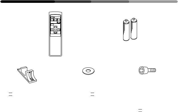
 the box of accessories to confirm they have been properly provided.
1 Remote control unit &
2 Two AA batteries &
3 Two stands &
4 Two washers &
5 Two bolts &
6 Operating Instructions &
Cocher la case 

 en face des accessoires afin de confirmer que ceux-ci sont bien présents.
1 Télécommande &
2 Deux piles AA &
3 Deux supports &
4 Deux rondelles &
5 Deux boulons &
6 Mode d'emploi &
Zur Überprüfung, ob alle angegebenen Zubehörteile ordnungsgemäß geliefert wurden, kreuzen Sie jeweils das betreffende Kästchen 

 an.
an.
1 Fernbedienung &
2 Zwei AA-Batterien &
3 2 Sockel &
4 2 Unterlegscheiben &
5 2 Schrauben &
6 Bedienungsanleitung &
6
<ARE1356>
En/Fr/Ge
PANEL FEATURES AND FUNCTIONS CARACTERISTIQUES ET FONCTIONS DES PANNEAUX TASTEN, EINSTELLUNGEN UND FUNKTIONEN
Remote Control Unit Commande à distance Fernbedienung
1
 STANDBY/ON
VIDEO Y/C RGB 1
2
RGB 2
INPUT
SELECT
3 MENU
MENU
SET
4


 Î
Î
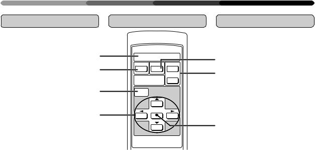
1 STANDBY/ON button:
Turns on/shuts off the power.
2VIDEO button:
Applicable only when the optional video card is used.
3MENU button:
Switches between the menu and ordinary screens.
4ADJUST button:
Use to adjust the picture quality.
5Y/C button:
Applicable only when the op-
tional video card is used.
6RGB-1 & 2 buttons:
Select RGB-1 (BNC terminal) and RGB-2 (MINI D-SUB termi-
nal) respectively as the input functions.
7SET button:
Use to finalize menu selections when adjusting picture quality.
1Bouton STANDBY/ON (= alimentation):
Pour la mise sous tension/hors tension
2Bouton VIDEO:
Uniquement applicable si la carte vidéo en option est utilisée.
3Bouton MENU:
Commutation entre les écrans
de menu et les écrans ordinaires
4Bouton ADJUST (= réglage):
Réglage de la qualité de l’image
5 Bouton Y/C:
Uniquement applicable si la carte vidéo en option est utilisée.
6Boutons RGB-1 & 2:
Sélection de RGB-1 (borne BNC) et de RGB-2 (borne MINI D-SUB) en tant que fonction d’entrée
7Bouton SET (= sélection):
Finalisation des sélections de menu lors du réglage de la qualité de l’image
5
6
7
1STANDBY/ON-Taste:
Schaltet die Netzspannung ein/ aus.
2VIDEO-Taste:
Alleen van toepassing bij gebruik van de optionele
videokarte.
3 MENU-Taste:
Schaltet die Menüoberfläche ein und aus.
4 ADJUST-Taste:
Funktionstasten, um die Einstellungen vorzunehmen.
5Y/C-Taste:
Alleen van toepassing bij
gebruik van de optionele videokarte.
6 RGB-1 & 2-Tasten:
Aktiviert RGB Eingang 1 (BNCRGBS) und RGB Eingang 2 (D- SUB).
7SET-Taste:
Aktiviert und bestätigt die Einstellungen.
7
<ARE1356>
En/Fr/Ge
PANEL FEATURES AND FUNCTIONS
CARACTERISTIQUES ET FONCTIONS DES PANNEAUX
TASTEN, EINSTELLUNGEN UND FUNKTIONEN
Control and Rear |
Panneau de |
Anschlüsse und |
Panels |
commande et |
Bedienungstasten |
|
panneau arrière |
|
STANDBY /ON
INPUT
MENU
ADJUST
SET
<Control Panel>
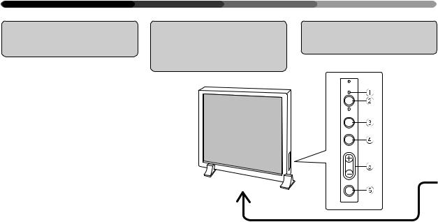
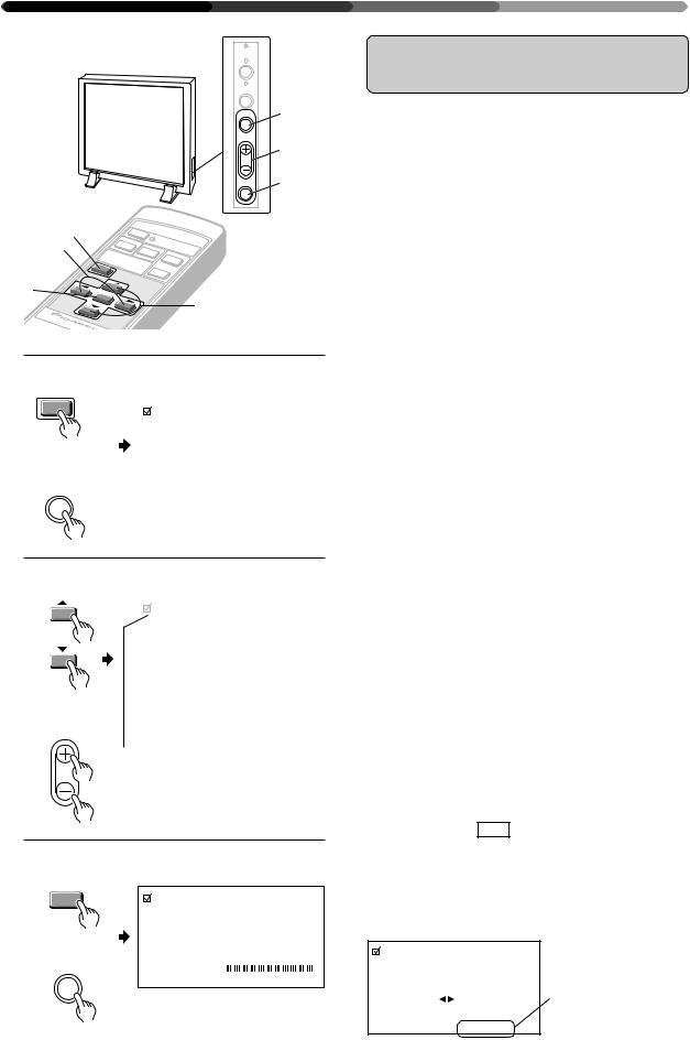
1STANDBY/ON indicator
The indicator is red when in standby mode and turns green when the power to the display is turned on. If the optional video card (PDA-4004) is not installed properly, the STANDBY indicator blinks as described below to inform the use of abnormality.
•Blinking twice
Only the terminals are installed: Install the video card.
•Blinking three times
Only the video card is installed:
Install the terminals.
2STANDBY/ON button
Press to turn the power to the
display on and off.
3INPUT button
Press to switch the various in-
put functions.
4 MENU button
Press to enter the menu screen and exit from it.
5ADJUST button
Use the +/– buttons to adjust picture quality.
6SET button
Press to finalize menu selections when adjusting picture quality.
<Panneau de commande>
1Témoin STANDBY/ON (= en attente/marche)
Ce témoin est rouge lorsqu’il est dans le mode en attente et devient vert lorsque l’écran est mis sous tension. Si la carte vidéo en option (PDA-4004)n'estpascorrectement installée, le témoin STANDBY clignote comme il est dit cidessous pour signaler cette anomalie.
•Deux clignotements
Seuls les bornes sont installées: Installer la carte vidéo.
•Trois clignotements
Seule la carte vidéo est installée:
Installer les bornes.
2Bouton STANDBY/ON (= Alimentation)
Appuyersurceboutonpourmettre
l’écransoustensionethorstension.
3Bouton INPUT (= entrée)
Appuyer sur ce bouton pour la commande des différentes
fonctions d’entrée.
4 Bouton MENU
Appuyersurceboutonpourentrer dans l’écran menu et en sortir.
5Bouton ADJUST (= réglage)
Utiliser les boutons +/– pour ajuster la qualité de l’image
6Bouton SET (= sélection)
Appuyer sur ce bouton pour finaliserlessélectionsdemenulors du réglage delaqualité de l’image.
<Control Panel> <Panneau de commande> <Seitliche Tasten>
<Bedienungstasten>
1STANDBY/ON-Leuchtdiode
Die Leuchtdiode leuchtet rot auf, wenn die Bereitsschaftsschaltung an ist, und wechselt zu grün, wenn das Display eingeschaltet ist. Falls die optionale Videokarte (PDA4004) nicht richtig eingesetzt ist, blinkt die STANDBY-Leuchtdiode gemäß folgender Beschreibung, um den Benutzer vor einer ungewöhnlichen Bedingung zu warnen.
•Blinkt zweimal
Nur die Klemmen sind eingebaut:
Bauen Sie die Videokarte ein.
•Blinkt dreimal
NurdieVideokarteisteingebaut: Bauen Sie die Klemmen ein.
2POWER-Taste
Mit dieser Taste wird das Gerät einund ausgeschaltet.
3INPUT-Taste
Mit dieser Taste werden die Eingänge umgeschaltet.
4MENU-Taste
Mit dieser Taste wird die Menüoberfläche aktiviert.
5ADJUST-Taste
Mit den +/– Tasten werden die Einstellungen vorgenommen.
6SET-Taste
Mit dieser Taste werden die Einstellungen aktiviert und bestätigt.
8
<ARE1356>
En/Fr/Ge
PANEL FEATURES AND FUNCTIONS
CARACTERISTIQUES ET FONCTIONS DES PANNEAUX
TASTEN, EINSTELLUNGEN UND FUNKTIONEN
7 8 90 - = ~ ! @ |
# |
$ |
% ^ |
OFF ON |
|
OFF ON |
75 (Ω) 2.2k |
VD |
HD |
B |
G |
R |
REMOTE |
RGB-2 |
G ON SYNC |
SYNC |
|
(H/V SYNC) |
RGB-1 |
(ON SYNC) |
RS-232C |
<Rear Panel Terminal/Connections to Power Source>
<Bornes du panneau arrière/Connexions à la source d’alimentation> <Hintere Anschlußleiste / Netzanschluß>
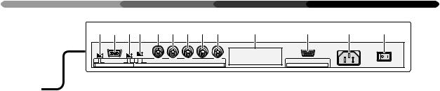
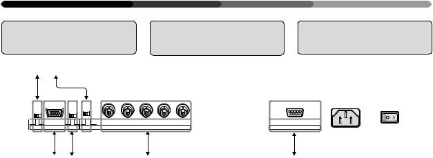
<Rear Panel Terminals/Connections to Power Source>
RGB-2 input terminals
7Remote control out switch (ON/OFF)
This switch will output remote control commands from the RGB-2 (D-SUB 15-pin) terminal to control external peripheral devices planned for future sales release. Normally be sure to use set to OFF. When this switch is set to ON, the optional downconverter (PDA-4003) can be remote controlled through the remote sensor on the main
unit.
8 MINI D-SUB 15-pin terminal
9G on Sync mode selection switch (ON/OFF)
If the images become greenish when an external device is connected to the RGB-2 input terminal, turn ON the G on SYNC
mode. Normally set to OFF.
RGB-1 input terminals
0Sync Signal Input Impedance switch (75 Ω/2,2 kΩ)
-Vertical Sync Signal Input terminal: (75 Ω/2,2 kΩ, switchable with the Sync Signal Input Im-
pedance switch)
=Horizontal or Composite Sync Signal Input terminal: (75 Ω/ 2,2 kΩ, switchable with the
Sync Signal Input Impedance
switch)
~ Blue Signal Input terminal: 75 Ω
!Green or Green with Sync Sig-
nal Input terminal (ON SYNC): 75 Ω
@ Red Signal Input terminal: 75 Ω
#Protection cover for installation hole of input terminals of optional video card. (Do not open this except when using the op-
tional video card (PDA-4004).) $ Control Signal Input terminal
(RS-232C compliance) % AC inlet
^ MAIN POWER switch
<Bornes du panneau arrière/ Connexions à la source d’alimentation>
Bornes d’entrée RGB-2
7Contacteur d’émission de commandes à distance (ON/OFF = MARCHE/ARRET)
Ce contacteur émet les commandes à distance en provenance de la borne RGB-2 (D-SUB 15 broches) vers les périphériques externes qui seront vendus à l’avenir.S’assurerqueleréglageest sur OFF. Lorsque ce contacteur est sur la position marche, le convertisseur informatique en option (PDA-4003) peut être commandé à distance par l'intermédiaire du capteur de télécommandedel'unitéprincipale.
8 Borne 15 broches MINI D-SUB
9 G sur bouton de sélection du mode Sync (ON/OFF = MARCHE/ ARRET)
Silesimagesdeviennentverdâtres lorsqu’un dispositif extérieur est raccordéauterminald’entréeRGB- 2, amener G sur le mode SYNC. Normalement,celui-ciestréglésur OFF (= arrêt).
Bornes d’entrée RGB-1
0Commutateur d’impédance
d’entrée du signal de synchronisation (75 Ω/2,2 kΩ)
-Borne d’entrée du signal de synchronisation vertical (75 Ω/2,2 kΩ, commutable avec le commutateur d’impédance
d’entrée du signal de synchronisation)
=Borne d’entrée du signal de
synchronisation horizontal ou composite:(75Ω/2,2kΩ,commutable avec l’interrupteur
d’impédanced’entréedusignalde synchronisation)
~Borne d’entrée du signal bleu : 75 Ω
!Borne d’entrée du signal vert ou
vert avec signal de synchronisation (ON SYNC): 75 Ω.
@Borne d’entrée du signal rouge: 75 Ω
#Couvercle de protection pour l’orifice d’installation des bornes d’entrèe de la carte vidèo en option. (Ne pas ouvrir ce couvercle, à moinsquel'onutiliselacartevidéo en option (PDA-4004).)
$ Borne d’entrée du signal de commande (Conforme au standard RS-232C)
% Prise c.a.
^ Interrupteur général POWER
<Anschlußleiste>
RGB 2-Eingang
7EIN-/AUS-Schalter der Fernbedienung (ON/OFF)
Mit diesem Schalter können Fernbedienungsbefehle über den Anschluß RGB-2 (D-SUB, 15-Pin- Buchse) ausgegeben werden, um zukünftiges Zubehör zu steuern.
Für den Normalbetrieb unbedingt auf OFF stellen. Wenn dieser Schalter auf ON gestellt ist, kann der optionale Downconverter (PDA-4003) über den Fernbedienungssensor des Hauptgerätes fernbedient werden.
8 MINI D-SUB 15-Pin-Eingang
9G an Sync-Moduswählschalter (ON/OFF)
Wird der Bildschirm grünlich, sobald ein externes Gerät an der Input-Schnittstelle von RGB - 2 - angeschlossen wird, schalten Sie G am Sync-Moduswählschalter auf ON (EIN), während es
normalerweise auf OFF (AUS) steht.
RGB 1-Eingang
0 Synchronsignal-Eingangs- Impedanz-Schalter (75Ω/2,2 kΩ).
-Vertikaler SynchronsignalEingang (75 Ω/2,2 kΩ, einstellbar mit dem Synchronsignal-
Eingangs-Impedanz-Schalter).
=Horizontaler oder kombinierter Synchroneingang: (75 Ω/2,2 kΩ, einstellbar mit dem Synchronsignal-Eingangs- Impedanz-Schalter).
~ Blaues Signal: 75 Ω
! Grünes Signal oder Grün mit
Synchronsignal-Eingang (ON SYNC): 75 Ω
@ Rotes Signal: 75 Ω
#Afdekplaat voor installatieopening van ingangsaansluitingen van optionele videokaart. (Nicht öffnen, ausgenommen bei
Verwendung der optionalen Videokarte (PDA-4004).)
$Kontrollsignal-Eingang (RS232C kompatibel)
% Netzanschluß
^ Netzschalter (MAIN POWER)
9
<ARE1356>
En/Fr/Ge
PANEL FEATURES AND FUNCTIONS
CARACTERISTIQUES ET FONCTIONS DES PANNEAUX
TASTEN, EINSTELLUNGEN UND FUNKTIONEN
Putting Batteries in |
Installation des piles |
Batterien in die |
the Remote Control |
dans la commande à |
Fernbedienung |
Unit |
distance |
einlegen |
|
1 |
2 |
|
9 |
3 |
|
( |
( |
|
|
|
|
|
9 |
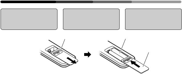
1To add or change the batteries, slide the cover of the battery compartment on the back of the remote control unit towards you while pushing down on it.
2Replace or add two AA batteries.
3Close the cover of the battery case.
1Pour ajouter ou remplacer des piles, faire coulisser le couvercle du compartiment à piles qui se trouve au dos de la commande à distance vers soi tout en pous-
sant vers le bas.
2Remplacement ou mise en place de deux piles AA
3Refermer le couvercle du compartiment a piles.
How to care for the remote control |
|
|
unit: |
Précautions à prendre pour la com- |
|
• |
Do not drop the remote control |
mande à distance: |
|
unit. |
• Ne pas laisser tomber la com- |
• Do not get the remote control unit |
mande à distance |
|
|
wet. |
• Protéger la commande à distance |
• |
Do not use or store the remote |
contre l'humidité |
|
control unit in the following loca- |
• Ne pas utiliser ni ranger la com- |
|
tions: |
mande à distance: |
|
In a place subject to direct sun- |
dans un endroit soumis au |
|
light |
rayonnement solaire direct |
|
In a place subject to heat radiated |
dans un endroit soumis à la |
|
by a heating system |
chaleur irradiée par un système |
|
In a humid place |
de chauffage |
|
|
dans un endroit humide. |
 CAUTION
•Never mix new and used batteries.
•Do not use different brands of batteries. Batteries of the same size may have different voltage.
•When the unit will not be used for a long time (more than one month), remove the batteries to prevent liquid leakage occurs, wipe up the liquid from the case and replace the batteries with new ones.
•Do not charge, short-circuit, break down or expose the batteries provided with the display to flames.
•When disposing of used batteries, please comply with governmental regulations or environmental public instruction’s rules that apply in your country or area.
10
<ARE1356>
En/Fr/Ge
 ATTENTION
•Ne jamais mélanger des piles neuves et usagées.
•Ne pas utiliser des marques de piles différentes. Des piles de même dimensionpeuventavoirdestensions différentes.
•Sil'unitédoitresterinactivependant une durée prolongée (plus d'un mois),enleverlespilesafindeprévenir les fuites de liquide à l'intérieur du compartiment à piles. En cas de fuite, essuyer le liquide qui s'écoule du compartiment et remplacer les pilesanciennespardespilesneuves.
•Nepascharger,court-circuiter,provo- quer la défaillance des piles fournies avecl'écrannilesexposeràlaflamme.
•Lorsque vous diposez de piles/batteries usées, veuillez vous conformer aux normes gouvernementales ou environnementales en vigueur dans votre pays ou région.
1Um Batterien einzulegen oder auszuwechseln, schieben Sie die Abdeckplatte des Batteriefaches auf der Rückseite der Fernbedienung in Ihre Richtung während Sie sie gleichzeitig ein-
drücken.
2 Legen Sie zwei AA-Batterien ein.
3Schließen Sie den Batteriefachdeckel.
Umgang mit der Fernbedienung:
•Lassen Sie die Fernbedienung nicht fallen.
•Lassen Sie die Fernbedienung nicht naß werden.
•Benutzen Sie oder lagern Sie die Fernbedienung nicht an den nachstehenden Orten:
An Orten, die der direkten Sonneneinstrahlung ausgesetzt sind.
An Orten, die der Wärmeeinstrahlung durch Heizkörper ausgesetzt sind.
An feuchten Orten.
 Vorsicht
•Benutzen Sie niemals gebrauchte und neue Batterien gleichzeitig.
•Benutzen Sie keine Batterien verschiedenerMarken.Batteriengleicher Größe können unterschiedliche Spannung haben.
•Wenn das Gerät über längere Zeit nicht benutzt wird (länger als einen Monat),solltenSiedieBatterienherausnehmen, um ein Auslaufen zu vermeiden. Läuft die Batterie dennochaus,wischenSiedieFlüssigkeit vorsichtig (Säure!) ab und ersetzen die Batterien durch neue.
•Die mit dem Display gelieferten Batterien dürfen nicht aufgeladen, kurzgeschlossen, auseinandergenommen oder offener Flamme ausgesetzt werden.
•Zur Entsorgung von verbrauchten Batterien beachten Sie bitte diegesetzlichen Vorschriften bzw. Umweltschutzbestimmungen Ihres Landes.
PANEL FEATURES AND FUNCTIONS
CARACTERISTIQUES ET FONCTIONS DES PANNEAUX
TASTEN, EINSTELLUNGEN UND FUNKTIONEN
Remote Control |
Portée de la |
Empfangsbereich |
Operation Range |
commande à |
der Fernbedienung |
|
distance |
|
Remote sensor
 Capteur de télédétection 7 m Sensorfenster
30 °
30 °
•If there is an obstacle between the remote control unit and the display, the unit may not operate with the remote control unit.
In this case, move the obstacle or change your position.
•As the battery power is weakens, the remote control operation range becomes shorter. If the operation range becomes too short, replace the batteries.
NOTES:
•The Plasma Display discharges weak infrared rays from the screen. When devices operated by infrared remote control units such as VCRs are installed near the Plasma Display, it may be difficult for the devices to receive signals from the remote control unit, or they may not be able to receive the signals at all.
•Depending on the installation environment, the Plasma Display may not be able to receive signals from the remote control unit or the operating distance of the remote control unit may shorten due to effects of the infrared rays discharged from the Plasma Display.
•The intensity of the infrared rays discharged from the screen changes according to the image displayed.
•Si un obstacle est présent entre la commande à distance et l'écran, l'unité peut ne pas fonctionner avec la commande à distance.
Dans ce cas, déplacer l'obstacle ou changer de position.
•Au fur et à mesure de l'épuisement de la pile, la portée de la commande à distance se réduit. Lorsque cette portée devient trop faible, remplacer les piles.
NOTES:
•L’écran à plasma émet des rayons infrarouges de faible intensité. Lorsque des dispositifs
commandés par des commandes à distance par infrarouge, comme des VCR, sont installés à proximité de l’écran à plasma, il peut être difficile pour les dispositifs de recevoir des signaux depuis la commande à distance. Il arrive parfois aussi qu’ils ne reçoivent aucun signal.
•En fonction de l’environnement d’installation, il est possible que l’écran à plasma ne soit pas en mesure de recevoir des signaux de la commande à distance ou bien que la distance de fonctionnement de la commande à distance soit raccourcie en
raison des effets des rayons infrarouges émis par l’écran à plasma.
•L’intensité des rayons infrarouges émis par l’écran varie en fonction de l’image affichée.
•Wenn sich zwischen der Fernbedienung und dem Display ein Hindernis befindet, kann es sein, daß das Gerät nicht mit der Fernbedienung betrieben werden kann. In diesem Fall entfernen Sie das Hindernis oder wechseln Sie Ihre Position.
•Wenn die Batteriespannung nachläßt, verringert sich der Empfangsbereich der Fernbedienung. Wenn der Empfangsbereich zu klein wird, müssen die Batterien ersetzt werden.
Anmerkungen:
•Das Plasma-Display sendet schwache Infrarotstrahlen aus. Wenn sich in der Nähe des Plasma-Displays Geräte oder Vorrichtungen befinden, die durch Infrarotfernsteuerungen betrieben werden, wie beispielsweise VCRs, kann es sich für die Geräte als schwierig oder gar unmöglich erweisen, Signale von der Fernsteuerung zu empfangen.
•Je nach Installationsumgebung kann das Plasma-Display eventuell nicht in der Lage sein, Signale von der Fernsteuerung zu empfangen, oder aber der Betriebsabstand der Fernsteuerung verkürzt sich aufgrund der Wirkung der vom Plasma-Display ausgesandten Infrarotstrahlen.
•Die Intensität der vom Schirm ausgesandten Infrarotstrahlen schwankt je nach angezeigtem Bild.
11
<ARE1356>
En/Fr/Ge

VIEWING IMAGES ON YOUR PLASMA DISPLAY VISUALISATION DES IMAGES SUR L’ECRAN A PLASMA BILDWIEDERGABE AUF IHREM PLASMA-DISPLAY
/ON |
2, 4 |
STANDBY |
|
INPUT |
3 |
MENU |
|
ADJUST |
|
SET |
|
RS-232C
2, 4
VIDEO
INPUT
SELECT
MENU
1
1, 4
|
S |
|
|
|
|
TA |
|
|
|
|
|
ND |
|
|
Y/C |
|
BY |
/ON |
|
|
RGB |
|
||
|
|
|
|
|
|
|
1 |
|
|
RGB |
2 |
|
3 |
|
STANDBY /ON
2 |
|
Main unit |
|
|
|
|
Unité principale |
|
|
Remote control |
Hauptgerät |
|
||
|
|
|||
Commande à distance |
STANDBY |
STANDBY |
||
Fernbedienung |
||||
/ON |
||||
|
|
/ON |
|
|
|
STANDBY/ON |
|
|
|
3 Remote control |
|
|
||
|
Commande à distance |
|
|
|
|
Fernbedienung |
|
|
|
|
RGB 1 |
|
RGB 1 |
|
|
|
|
||
|
Main unit |
|
|
|
|
Unité principale |
|
|
|
|
Hauptgerät |
|
|
|
|
INPUT |
|
|
|
4 |
Remote control |
Main unit |
|
|
1 |
|
|||
Commande à distance |
Unité principale |
|
||
|
Fernbedienung |
Hauptgerät |
|
|
1 Input the power to the main unit.
The standby indicator will flash in red for about 4 seconds. The display then enters standby state and the indicator remains lit.
NOTE:
The buttons on the main unit and remote control unit, and the external control commands are not accepted by the display unit while the standby indicator is flashing in red.
If the optional video card (PDA-4004) is not installed properly, the STANDBY indicator blinks as described below to inform the use of abnormality.
•Blinking twice
Only the terminals are installed: Install the video card.
•Blinking three times
Only the video card is installed: Install the terminals.
2 Turn on the Display.
The STANDBY indicator turns green.
3 Select an input source.
•Press the INPUT button on the main unit. Each time press changes the input source as follows:
RGB 1
RGB 2
•To choose an input source with the remote control, press the INPUT SELECT button.
•The function cannot be switched at the MENU screen.
“NO SYNC!” is displayed if no signal is being input . “OUT OF RANGE!” is displayed if the signal being input cannot be processed on this set.
4 After use, turn off the power.
1 Turn off the power.
The standby indicator flashes in red for about 4 seconds, then remains lit (standby state).
2 Turn off the MAIN POWER switch on the main unit.
The STANDBY/ON indicator will dim and the power to the unit will be turned off.
STANDBY/ON |
STANDBY |
STANDBY |
|
/ON |
/ON |
|
|
2
STANDBY /ON
NOTES:
•The buttons on the main unit and remote control unit, and the external control commands are not accepted by the display while the standby indicator is flashing in red.
•Do not display the same image (still images, etc.) for a long time as the image may stick onto the screen.
12
<ARE1356>
En/Fr/Ge
VIEWING IMAGES ON YOUR PLASMA DISPLAY VISUALISATION DES IMAGES SUR L’ECRAN A PLASMA BILDWIEDERGABE AUF IHREM PLASMA-DISPLAY
1 Alimentation de l’écran en énergie
Le témoin en attente rouge clignote pendant 4 secondes environ. Ensuite, l’écran passe en mode attente et ce témoin reste allumé.
NOTE:
Les boutons de l’unité principale et de la commande à distance, ainsi que les instructions de commande extérieures ne sont pas acceptés par l’écran tant que le témoin en attente rouge clignote.
Si la carte vidéo en option (PDA-4004) n'est pas correctement installée, le témoin STANDBY clignote comme il est dit ci-dessous pour signaler cette anomalie.
•Deux clignotements
Seuls les bornes sont installées: Installer la carte vidéo.
•Trois clignotements
Seule la carte vidéo est installée: Installer les bornes.
1 Schalten Sie den Hauptschalter ein.
Die Bereitschafts-Leuchtdiode blinkt etwa 4 Sekunden lang rot. Dann wechselt das Gerät in den Bereitschaftszustand, und die BereitschaftsLeuchtdiode leuchtet.
Anmerkung:
Solange die Bereitschafts-LED rot blinkt, reagiert das Display weder auf die Tasten des Hauptgerätes oder der Fernbedienung, noch auf externe Befehle.
Falls die optionale Videokarte (PDA-4004) nicht richtig eingesetzt ist, blinkt die STANDBY-Leuchtdiode gemäß folgender Beschreibung, um den Benutzer vor einer ungewöhnlichen Bedingung zu warnen.
•Blinkt zweimal
Nur die Klemmen sind eingebaut: Bauen Sie die Videokarte ein.
•Blinkt dreimal
Nur die Videokarte ist eingebaut: Bauen Sie die Klemmen ein.
2 Allumage de l’écran
Le témoin STANDBY (en attente) devient vert.
3 Sélection d’une source d’entrée
•Pousser sur le bouton de commutation INPUT (entrée) de l’unité principale.
Chaque pression modifie la source d’entrée comme
suit :
RGB 1
RGB 2
•Pour sélectionner une source d’entrée avec la commande à distance, appuyer sur le bouton INPUT SELECT (= sélection d’entrée)
•La fonction ne peut pas être commutée à l’écran MENU.
«NO SYNC !» s’affiche en l’absence de réception d’un signal à la sélection de RGB-1 ou de RGB-2.
«OUT OF RANGE!» s’affiche si le signal reçu ne peut pas être traité par cet appareil.
4Après utilisation, mettre hors tension
1 Mise hors tension
Le témoin en attente rouge clignote pendant environ 4 secondes, puis reste allumé (état en attente).
2 Eteindre l’interrupteur MAIN POWER (= sur l’unité principale
Le témoin STANDBY/ON diminue d’intensité et l’alimentation de l’unité est coupé.
NOTES:
•Les boutons de l’unité principale et de la commande à distance, ainsi que les instructions de commande extérieures ne sont pas acceptées par l’écran tant que le témoin en attente rouge continue à clignoter.
•Ne pas afficher la même image (images immobiles, etc.) pendant une durée prolongée étant donné que l’image peut alors rester collée à l’écran.
2 Schalten Sie das Display ein.
Die Bereitschafts-STANDBY wird grün.
3 Wählen Sie die Eingangsquelle.
•Drücken Sie die Eingangstaste am Hauptgerät. Bei jedem Tastendruck wechselt die Eingangsquelle
wie folgt:
RGB 1
RGB 2
•Wenn Sie per Fernbedienung eine Eingangsquelle wählen möchten, drücken Sie bitte eine INPUT SELECT-Taste.
•Diese Funktion kann nicht mit der MENUOberfläche eingestellt werden.
Falls bei Wahl von RGB-1 oder RGB-2 kein Signal anliegt, wird „NO SYNC!“ angezeigt.
Falls ein Signal anliegt, das nicht verarbeitet werden kann, erscheint „OUT OF RANGE!“.
4Nach dem Gebrauch schalten Sie den Netzschalter aus.
1 Schalten Sie den Strom aus.
Die Bereitschafts-LED blinkt etwa 4 Sekunden lang rot, und leuchtet dann kontinuierlich (Bereitschaftsstatus).
2Schalten Sie den Netzschalter am Hauptgerät aus.
Die Bereitschafts-STANDBY/ON erlischt, und die Stromzufuhr zum Gerät ist ausgeschaltet.
Anmerkungen:
•Solange die Bereitschafts-STANDBY rot blinkt, reagiert das Display weder auf die Tasten des Hauptgerätes oder der Fernbedienung, noch auf externe Befehle.
•Zeigen Sie nicht dasselbe Bild (stillstehende Bilder usw.) über einen längeren Zeitraum an, da dieses
auf dem Schirm “festkleben“ kann. |
13 |
|
<ARE1356> |
|
En/Fr/Ge |
HOW TO ADJUST PICTURE QUALITY COMMENT REGLER LA QUALITE DE L’IMAGE EINSTELLEN DER BILDQUALITÄT
STANDBY /ON
INPUT
MENU |
1, 5 |
ADJUST |
2, 4 |
|
|
SET |
3 |
1, 5 |
|
|
V |
|
|
|
|
|
|
|
4 |
|
|
|
IDE |
|
|
STAN |
|
||
|
|
|
|
|
O |
Y |
/C |
DBY/ON |
||
|
S |
INP |
U |
|
|
|
RGB 1 |
|||
|
|
EL |
|
T |
|
|
|
|
||
|
|
|
EC |
|
R |
|
||||
|
|
|
|
|
T |
|
|
|||
|
|
|
|
|
|
|
|
|
GB |
|
|
|
ME |
|
|
|
|
2 |
|
||
|
|
|
|
|
|
|
|
|||
|
|
|
|
N |
|
|
|
|
|
|
3 |
|
|
|
|
U |
|
|
|
|
|
SE |
T |
|
|
|
|
|
|
|
|
|
2
1 Remote control Commande à distance Fernbedienung
MENU
Main unit
Unité principale
Hauptgerät
MENU
PICTURE PARAMETER |
|
|
|
|
|
|
|
||||||||||||||
CONTRAST |
|
|
|
|
|
|
|
|
|
|
|
|
|
|
|
|
|
|
|
|
|
|
|
|
|
|
|
|
|
|
|
|
|
|
|
|
|
|
|
|
|
|
|
BRIGHT. |
|
|
|
|
|
|
|
|
|
|
|
|
|
|
|
|
|
|
|
|
|
|
|
|
|
|
|
|
|
|
|
|
|
|
|
|
|
|
|
|
|
|
|
CLK. FRQ. |
+ 1 0 |
|
|
|
|||||||||||||||||
CLK. PHS. |
|
|
|
|
|
|
|
|
|
|
|
|
|
– |
5 |
|
|
|
|||
HOR. POS. |
+ |
0 |
|
|
|
||||||||||||||||
VER. POS. |
8 |
|
|
|
|||||||||||||||||
INIT. |
|
|
|
|
|
|
|
|
|
|
|
|
|
|
|
|
|
|
|
|
|
SET : SEL. |
|
|
|
MENU : EXIT |
|||||||||||||||||
2
Remote control Commande à distance Fernbedienung
Main unit
Unité principale
Hauptgerät
ADJUST
PICTURE PARAMETER |
|
|
|
|
|
|
|
||||||||||||||
CONTRAST |
|
|
|
|
|
|
|
|
|
|
|
|
|
|
|
|
|
|
|
|
|
|
|
|
|
|
|
|
|
|
|
|
|
|
|
|
|
|
|
|
|
|
|
BRIGHT. |
|
|
|
|
|
|
|
|
|
|
|
|
|
|
|
|
|
|
|
|
|
|
|
|
|
|
|
|
|
|
|
|
|
|
|
|
|
|
|
|
|
|
|
CLK. FRQ. |
+ 1 0 |
|
|
|
|||||||||||||||||
CLK. PHS. |
|
|
|
|
|
|
|
|
|
|
|
|
|
– |
5 |
|
|
|
|||
HOR. POS. |
+ |
0 |
|
|
|
||||||||||||||||
VER. POS. |
8 |
|
|
|
|||||||||||||||||
INIT. |
|
|
|
|
|
|
|
|
|
|
|
|
|
|
|
|
|
|
|
|
|
SET : SEL. |
|
|
|
MENU : EXIT |
|||||||||||||||||
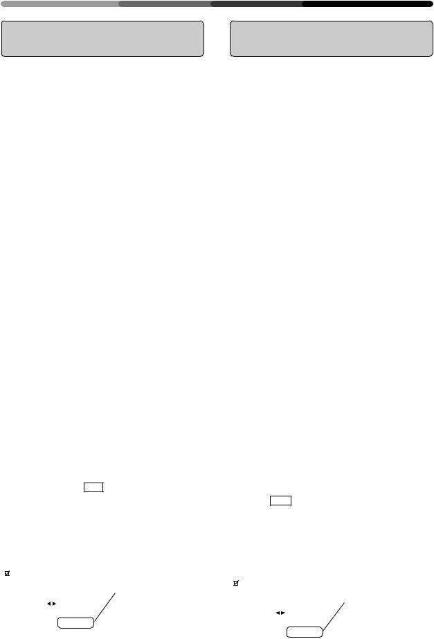
The currently selected item will be displayed in purple.
L’option sélectionnée apparaît en pourpre.
Das gewählte Item wird purpurfarbig wiedergegeben.
3 Remote control Commande à distance Fernbedienung
SET |
|
|
PICTURE PARAMETER |
Main unit |
|
Unité principale |
|
Hauptgerät |
CONTRAST |
SET |


 : ADJ. SET : EXIT
RGB-1 (BNC) or RGB-2 (MINI D- SUB) Input
Adjust the picture quality for each input: the RGB-1 (BNC), the RGB-2 (MINI D-SUB).
* Refer to page 37 for the sources.
1Switch to the MENU screen.
2Choose the item to be adjusted.
3Finalize your choice.
Make adjustment concerning each item as follows:
CONTRAST .. Adjusts the contrast of the picture according to the brightness of the environment so that you can watch the picture easier.
BRIGHT ......... Adjusts the brightness of the picture so that you can watch the darker parts of the picture easier.
CLK.FRQ. ...... When part of the letters in the picture (–32 to +32) is missing, or if the displayed image
is distorted as a rainbow-like noise, use this function. This function is to adjust the frequency of the internal clock signal for the video signal input.
NOTE:
HOR.POS may need to be adjusted in some cases if CLK.FRQ has been adjusted.
CLK.PHS. ...... When some letters in the picture (–128 to +127) flicker and the color becomes distorted, use this function. Adjust it to minimize the flicker and the color distortion. This function is to adjust the phase of the internal clock signal, which is adjusted with the CLK. FRQ
function.
HOR.POS. ..... Adjust the horizontal position of the (–32 to +32) picture.
VER.POS....... Adjust the vertical position of the pic- (–32 to +32) ture.
INIT. .............. Returns the above picture settings to their center values. *1
*1
When you select INIT. , the message on the right is displayed. Select “YES” or “NO” by using the 2 or 3button.
Selecting “YES” and pressing the SET button sets back all picture quality settings to their default values. When “NO” is selected, all settings will remain as they are.
PICTURE PARAMETER |
If “NO” has been selected, |
|
SET:EXIT will be displayed |
||
|
||
|
here. |
|
I N I T I AL I ZE? |
If “YES” has been selected, |
|
SET:INIT will be displayed. |
||
YES NO |
||
|
SET : EX I T
14
<ARE1356>
En/Fr/Ge
Entrée RGB-1 (BNC) ou RGB-2 (MINI D-SUB)
Régler la qualité de l’image pour chaque entrée : RGB- 1 (BNC), RGB-2 (MINI D-SUB).
* Référez-vous à la page 38 pour les sources.
1Passage à l’écran MENU
2Sélectionner l’option à régler
3Finalisation de la sélection
Opérer les réglages pour chaque option comme suit :
CONTRAST ... Règle le contraste de l’image en fonction de la luminosité de l’environnement de manière à pouvoir visionner l’image avec un plus grand confort.
BRIGHT ......... Règle la luminosité de l’image de manière à pouvoir visionner les parties plus sombres de l’image avec un plus grand confort.
CLK.FRQ ....... Utiliser cette fonction. Si une partie des (–32 à +32) lettres de l’image est absente, ou si
l’image affichée est déformée en tant que bruit iridescent.
Cette fonction sert à régler la fréquence du signal d’horloge interne pour l’entrée du signal vidéo.
NOTE :
HOR.POS devra être réglé dans certains cas si CLK.FRQ a été réglé.
CLK.PHS ....... Utiliser cette fonction. Lorsque certaines (–128 à +127) lettres de l’image scintillent et que la
couleur s’altère.
Régler pour minimiser le scintillement et la distorsion des couleurs. Cette fonction a pour but de régler la phase du signal d’horloge interne qui est réglée avec la fonction CLK.FRQ.
HOR.POS ...... Régler la position horizontale de (–32 à +32) l’image projetée
VER.POS ....... Règle la position verticale de l’image. (–32 à +32)
INIT. ............... Ramène les sélections d’image supérieures à leurs valeurs centrales. *1
*1
Si vous sélectionnez INIT. , le message à droite est affiché. Sélectionner “YES” ou “NO” en utilisant le bouton 2ou 3.
La sélection “YES” et l’enfoncement du bouton SET réinitialise tous les réglages de qualité de l’image à leurs valeurs par défaut.
Si “NO” est sélectionné, toutes les sélections restent comme elles sont.
PICTURE PARAMETER |
Si “NO” a été sélectionné, |
|
SET:EXIT sera affiché ici. |
||
|
||
|
Si “YES” a été sélectionné, |
|
I N I T I AL I ZE? |
SET:INIT sera affiché. |
|
|
||
YES NO |
|
|
SET : EX I T |
|
HOW TO ADJUST PICTURE QUALITY COMMENT REGLER LA QUALITE DE L’IMAGE EINSTELLEN DER BILDQUALITÄT
RGB-1 (BNC) oder RGB-2 (MINI D-SUB) Eingang
Für jeden Eingang sollte die Bildqualität eingestellt werden: für RGB-1 (BNC), RGB-2 (D-SUB).
*Die verschiedenen Quellen finden Sie auf Seite 39 dieser Bedienungsanleitung.
1Wechseln Sie zur MENU-Oberfläche.
2Wählen Sie die Funktion, die Sie einstellen möchten.
3Bestätigen Sie Ihre Wahl.
Jede einzelne Funktion beinhaltet die nachstehenden Einstellmöglichkeiten:
CONTRAST ... Regelt den Bildkontrast gemäß der Helligkeit der Umgebung, zur besseren Bilderkennung.
BRIGHT ......... RegeltdieHelligkeitdesBildes,zurbesseren Erkennung der dunklen Bildstellen.
CLK-FRQ ........ Wenn ein Teil der Buchstaben im Bild fe- (–32 bis +32) hlt oder die dargestellte Abbildung als regenbogenartiges und rauschendes Bild wiedergegeben wird, können Sie diese Funktion benutzen, um die Frequenz des internen Taktsignals für den Videosignal-
Eingang einzustellen.
Anmerkung:
Nach einer Änderung von CLK.FRQ muß in manchen Fällen HOR.POS neu eingestellt werden.
CLK.PHS ........ Wenn manche Buchstaben im Bild flim- (–128 bis +127) mern und die Farben gestört sind, können Sie diese Funktion benutzen. Stellen Sie sie so ein, daß Flimmern und Farbstörung so weit wie möglich reduziert werden.MitdieserFunktionstellenSiedie Phase des internen Taktsignals, das mit der CLK.FRQ-Funktion geregelt wird, ein.
HOR.POS ....... Regelt die waagerechte Bildposition. (–32 bis +32)
VER.POS........ Regelt die senkrechte Bildposition. (–32 bis +32)
INIT. ............... Setzt die obengenannten Bildeinstellungen auf ihren Mittelwert zurück. *1
*1
Wenn Sie INIT. wählen, wird die rechts dargestellte Meldung angezeigt. Wählen Sie “YES“ oder “NO“, indem Sie die Taste 2 oder 3 drücken.
Wenn Sie “YES“ wählen und die SET-Taste drücken, werden alle Bild-Einstellmöglichkeiten auf die Standardwerte zurückgesetzt.
Wenn Sie “NO“ wählen, bleiben alle Einstellungen unverändert.
PICTURE PARAMETER |
Wenn “NO“ gewählt wurde, |
|
wird hier SET:EXIT angezeigt. |
||
|
||
|
Wenn “YES“ gewählt wurde, |
|
I N I T I AL I ZE? |
wird hier SET:INIT angezeigt. |
|
|
||
YES NO |
|
|
SET : EX I T |
|
15
<ARE1356>
En/Fr/Ge
HOW TO ADJUST PICTURE QUALITY COMMENT REGLER LA QUALITE DE L’IMAGE EINSTELLEN DER BILDQUALITÄT
4 |
1 |
|
|
Remote control |
PICTURE PARAMETER |
||
Commande à distance |
|||
Fernbedienung |
|
|
|
|
|
CONTRAST |
|
Main unit |
|
: ADJ. |
SET : EXIT |
|
|
|
|
Unité principale |
2 |
|
|
Hauptgerät |
PICTURE PARAMETER |
||
ADJUST |
|
||
|
|
|
|
|
|
CLK. FRQ. |
+ 1 0 |
|
|
: ADJ. |
SET : EXIT |
5 |
|
|
|
Remote control |
|
|
|
Commande à distance |
|
|
|
Fernbedienung |
|
|
|
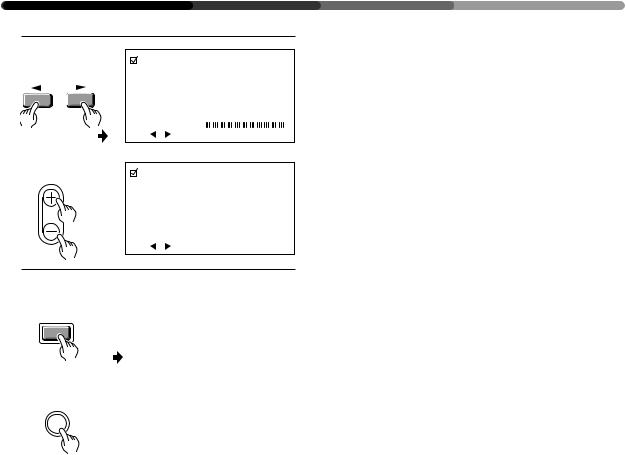
MENU |
|
Return to the normal screen. |
|
|
|
||
|
|
Ë Retour à l’écran normal. |
|
Main unit |
|
Zurück zur normalen Maske. |
|
Unité principale |
|
|
|
Hauptgerät |
|
|
|
MENU
16
<ARE1356>
En/Fr/Ge
4Adjust the picture quality concerning the selected item.
1 In case of CONTRAST and BRIGHT:
2In case of CLK.FRQ., CLK PHS., HOR.POS. and VER.POS.:
To return to the step-2 screen, press the SET button. Repeat steps 2 through 4 to adjust the other items.
5When you have completed the setting, return to the normal screen.

4Réglage de la qualité de l’image concernant l’option sélectionnée
1 En cas de CONTRAST et de BRIGHT
2En cas de CLK.FRQ, CLK.PHS, HOR.POS et VER.POS
Pour retourner à l’écran phase-2, appuyer sur le bouton SET.
Répéter les étapes 2 à 4 pour régler les autres options.
5Une fois la sélection terminée, revenir à l’écran normal.
HOW TO ADJUST PICTURE QUALITY COMMENT REGLER LA QUALITE DE L’IMAGE EINSTELLEN DER BILDQUALITÄT
4Stellen Sie die Bildqualität der gewählten Funktion ein.
1 Für CONTRAST und BRIGHT
2 Für CLK.FRQ, CLK.PHS., HOR.POS und VER.POS
Um zur Oberfläche von Schritt 2 zurückzukehren, drücken Sie die SET-Taste.
Wiederholen Sie Schritte 2 bis 4, um auch die anderen Funktionen einzustellen.
5 Wenn Sie die Bildeinstellung abgeschlossen haben, kehren Sie zur normalen Oberfläche zurück.
17
<ARE1356>
En/Fr/Ge
INSTALLATION
INSTALLATION
MONTAGE
Using the Display |
Utilisation de l’écran |
Benutzung des |
|
with Stands |
avec supports |
Displays auf Sockeln |
|
1 |
Front |
3 |
|
Avant |
|
||
|
Vorderseite |
|
|
|
590 |
|
|
Back Arrière
Rückseite 100
Unit: mm
100 Unité: mm Einheit mm
2 |
4 |
|
|
Use a hexagonal wrench. (6 mm) |
A |
A' ’ |
Utiliser une clé hexagonale (6 mm) |
Verwenden Sie einen Sechskantschlüssel (6 mm). |
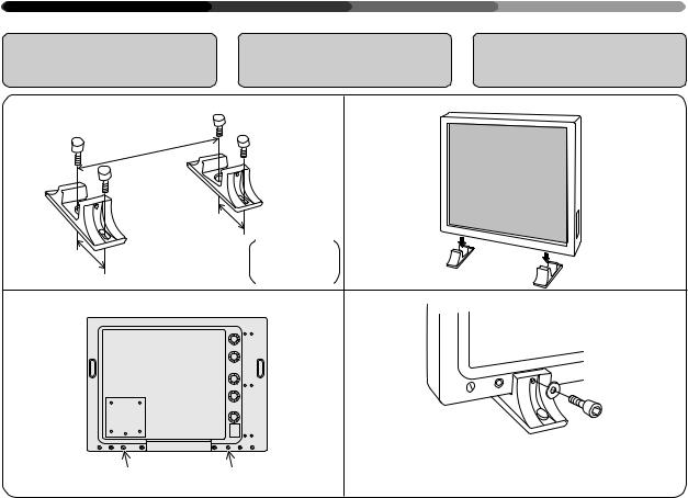
Always be sure to have your display installed by a trained professional or by your dealer.
To use the stands provided with the main unit, fit the main unit with them in accordance with the following procedure:
1.Use four bolts to fix the stands provided with the display on the display stand.
2.Use a coin to remove hole rivets A and A’.
3.Insert the main unit into the stands.
4.Fix the main unit with the washers and bolts.
 CAUTION
Because this display has an extremely small footprint for its heavy weight of 30.6 kilograms, it is very unstable. Always be sure to work together with another person when unpacking, carrying, or installing the display.
Toujours faire installer l’écran par un professionnel compétent ou par le revendeur attitré.
Pour utiliser les supports prévus avec l’unité principale, monter ces supports selon la procédure ciaprès.
1.Utiliser quatre boulons pour fixer les supports fournis avec l’écran.
2.Utiliser une pièce de monnaie pour enlever les rivets A et A’.
3.Introduire l’unité principale dans les supports.
4.Fixer l’unité principale avec les rondelles et les boulons.
 ATTENTION
Etant donné que cet écran se caractérise par un contact au sol extrêmement réduit pour un poids élevé (30,6 kg), il se révèle très instable. Toujours travailler avec une autre personne lors du déballage, du transport ou de l’installation de l’écran.
Lassen Sie Ihr Display immer von einem Fachmann oder von Ihrem Fachhändler montieren.
Wenn Sie die mit dem Hauptgerät gelieferten Sockel verwenden möchten, montieren Sie das Display bitte wie nachfolgend beschrieben:
1.Befestigen Sie die mit dem Gerät gelieferten Sockel mit vier Schrauben auf der Unterlage.
2.Entfernen Sie die Abdeckplättchen Aund A’ mit Hilfe einer Münze.
3.Stellen Sie das Display auf die Sockel.
4.Befestigen Sie das Display mit den Unterlegscheiben und den Schrauben.
 Vorsicht
Da das Gerät gemessen an seinem Gewicht von 30,6 kg ein extrem kleines Gehäuse hat, ist es besonders instabil. Lassen Sie sich deshalb beim Auspacken, Tragen oder Montieren immer von einer zweiten Person helfen.
18
<ARE1356>
En/Fr/Ge
Installing the Display on a wall or Other Flat Surfaces
Installation de l’écran sur un mur ou d’autres surfaces plates
INSTALLATION
INSTALLATION
MONTAGE
Montage des Displays an einer Wand oder an anderen Flächen
1 |
2 |
1313to-20mm
13 à 20 mm
13 bis 20 mm
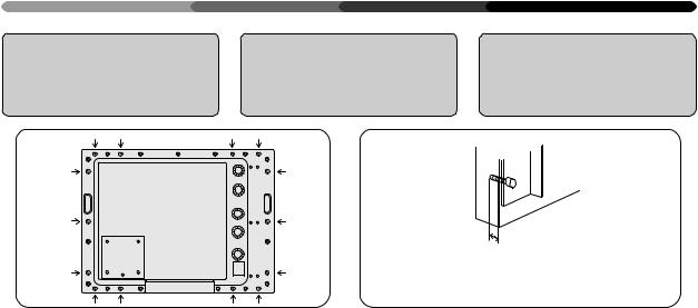
The display comes with bolt holes |
L’écran est fourni avec des trous de |
for attaching to a wall or other flat |
boulon qui permettent sa fixation à |
surface. |
un mur ou une autre surface plane. |
1. To use metal fittings for installation
Remove the hole rivets (indicated by arrows in the diagram above) and attach the metal fittings.
When installing fittings or installing the display, always be sure to have the work done by a trained professional or by your dealer.
2.Precautions on use of metal fittings for instal-
lation
Use bolts (M8) which is to be left by 13 to 20 mm inside the unit when fastened.
For installation positions, contact your nearest Pioneer authorized service station.
Note that Pioneer bears no responsibility whatsoever for any problems in installation/attachment nor for any accidents or damages caused by natural disasters, etc.
 WARNING
Use bolts which are less than 20 mm long inside the unit when fastened. Use of longer bolts will lead to damage of the internal circuit, electrical hazards, fire hazards, etc.
1.Utilisation de raccordements métalliques pour
l’installation
Enlever les rivets des orifices (c-à-d ceux indiqués par une flèche sur le schéma ci-dessus) et fixer les accessoires métalliques.
Lors de l’installation des accessoires ou de l’installation de l’écran, toujours faire réaliser ce travail par un professionnel compétent ou par le revendeur attitré.
2.Précautions d’utilisation de raccordements métalliques pour
l’installation
Utiliser les boulons (M8) qui doivent laisser un espace libre de 13 à 20 mm à l’intérieur de l’écran lorsqu’ils sont fixés.
Pour les positions d’installation, prendre contact avec votre service après-vente PIONEER agréé le plus proche.
Il est à noter que Pioneer n’est aucunement responsable de tous problèmes d’installation/de raccordement, ni d’accidents ou d’endommagements provoqués par des catastrophes naturelles, etc.
 AVERTISSEMENT
Utiliser des boulons d’une longueur inférieure à 20 mm à l’intérieur de l’unité lors de sa fixation. L’utilisation de boulons plus longs peut endommager le circuit interne, entraîner des risques électriques, un danger d’incendie etc.
Das Display ist mit Schraublöchern für die Befestigung an einer Wand oder an sonstigen Flächen versehen.
1.Verwendung von MetallBefestigungsteilen für
die Montage
Entfernen Sie die Abdeckplättchen von den Löchern (in der obenstehenden Skizze mit Pfeilen gekennzeichnet) und befestigen Sie die Metall-Befestigungsteile.
Die Montage der Befestigungsteile oder des Displays sollte immer von einem Fachmann oder von Ihrem Fachhändler ausgeführt werden.
2.Vorsichtsmaßnahmen bei der Montage mit Metall-
Befestigungsteilen
Verwenden Sie Schrauben (M8), die nach dem Festschrauben noch 13 bis 20 mm tief im Gerät verbleiben. Lassen Sie sich von Ihrem zuständigen PioneerVertragshändler die für die Montage geeigneten Stellen aufzeigen.
Bitte beachten Sie, daß Pioneer weder für Probleme, die bei der Montage/Befestigung auftreten, noch für Unfälle oder Schäden, die durch Naturkatastrophen usw. entstehen, eine Haftung übernimmt.
 Warnung:
Verwenden Sie Schrauben, die nach dem Festschrauben weniger als 20 mm in das Gerät hineinragen. Die Verwendung längerer Schrauben führt zu Beschädigungen im Geräteinneren und damit eventuell zu elektrischen Störungen, Feuer
usw.
19
<ARE1356>
En/Fr/Ge
CONNECTIONS
CONNEXIONS
ANSCHLÜSSE
Diagram of Equip- |
Schéma de |
Übersicht der |
ment connected |
l’équipement connecté |
Anschlußmöglichkeiten |
1 2 |
|
|
OFF ON |
OFF ON |
75 (Ω) 2.2k |
REMOTE |
RGB-2 G ON SYNC |
SYNC |
VD |
HD |
B |
G |
R |
|
(H/V SYNC) |
RGB-1 |
(ON SYNC) |
RS-232C |
3 4 |
5 |
6 |
1This switch will output remote control commands from the RGB-2 (D-SUB 15-pin) terminal to control external peripheral devices planned for future sales
release. Normally be sure to use set to OFF.
2Switch this according to the output impedance of the sync signal of the device connected
when inputting to RGB1.
Set to 2.2 kΩ when the output impedance of the sync signal of
the device is other than 75 Ω. 3 To: Personal computers
4If the images become greenish when an external device is connected to the RGB-2 input ter-
minal, turn ON the G on SYNC mode. Normally set to OFF.
5To: Personal computers, external RGB decoders, or other devices with RGB output ports
6To: Personal computers, when controlling the Plasma Display with the personal computer.
*In case of a 25-pin RS-232C connecter, use a conversion connector available on your local market.
*Refer to page 37 for the sources.
1Ce contacteur émet les commandes à distance en provenance de la borne RGB-2 (D- SUB 15 broches) vers les périphériques externes qui seront vendus à l’avenir.
S’assurer que le réglage est sur OFF.
2Actionnerceboutonenfonctionde l’impédance de sortie du signal sync du dispositif connecté lors de
l’entrée dans RGB1.
Régler sur 2,2 KΩ lorsque l’impédance de sortie du signal
sync du dispositif est différente de 75Ω.
3 Vers : Ordinateurs personnels
4Silesimagesdeviennentverdâtres lorsqu’un dispositif extérieur est raccordéauterminald’entréeRGB- 2, amener G sur le mode SYNC. Normalement,celui-ciestréglésur
OFF (=arrêt).
5Vers : Ordinateurs personnels, décodeurs RGB extérieurs ou
autres dispositifs avec ports de sortie RGB
6Vers : Ordinateurs personnels en cas de commande de l’écran à plasma par un ordinateur personnel
*En cas d’utilisation d’un connecteur RS-
232Cà25broches,utiliserunconnecteur de conversion vendu localement.
*Référez-vous à la page 38 pour les sources.
1Mit diesem Schalter können Fernbedienungsbefehle über den Anschluß RGB-2 (D-SUB, 15-Pin-Buchse) ausgegeben werden, um zukünftiges Zubehör zu steuern.
Für den Normalbetrieb
unbedingt auf OFF stellen.
2Schalten Sie dies gemäß der Ausgangsimpedanz des Synchronisierungssignals des angeschlossenenGerätesbeiInput
nach RGB1.
Stellen Sie auf 2.2 kΩ ein, wenn die Ausgangsimpedanz des Synchronisierungssignals einen
anderen Wert als 75 Ω aufweist. 3 An: Personal Computer
4Werden die Bilder grünlich, sobald ein externes Gerät an der InputSchnittstelle von RGB-2- angeschlossen wird, schalten Sie G am SYNC-Moduswählschalter auf ON (EIN), während es normalerweise auf OFF (AUS) steht.
5 An: Personal Computer, externe RGB-Decoder oder sonstige Geräte mit RGB-Ausgang;
6An: Personal Computer, wenn das Plasma-Display über einen PC bedient wird.
*Wenn Sie einen 25-Pin RS-232C
Anschluß benutzen, sollten Sie einen Übergangsstecker verwenden, der bei Ihrem Händler erhältlich ist.
*Die Quellen finden Sie auf Seite 39 dieser Bedienungsanleitung.
20
<ARE1356>
En/Fr/Ge
|
|
CONNECTIONS |
|
|
CONNEXIONS |
|
|
ANSCHLÜSSE |
Connecting a Per- |
Connexion d’un |
Anschluß eines |
sonal Computer to |
ordinateur personnel |
Personal Computers |
the Display |
à l’écran |
an das Display |
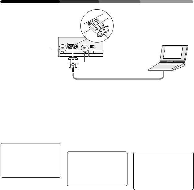
•Desk-top type
•Type de bureau
•Desktop
Normally be sure to use set |
|
|
|
|
to OFF. |
OFF ON |
OFF ON |
75 (Ω) 2.2k |
|
En temps normal, assurez- |
REMOTE RGB-2 |
G ON SYNC |
SYNC |
|
|
|
|
|
|
vous d’être en position OFF. |
|
1 |
|
|
Für den Normalbetrieb |
|
|
|
|
|
|
|
|
|
unbedingt auf OFF stellen. |
|
|
2 |
3 |
|
|
|
The method of connecting a personal computer to the unit varies with the type of computer. Before connecting the computer, read the instruction manual for the computer also.
La méthode de connexion d’un ordinateur personnel à l’écran varie en fonction du type d’ordinateur. Avant de raccorder l’ordinateur, lire également le manuel d’utilisation de l’ordinateur.
Das Verfahren beim Anschließen eines Personal Computers an das Gerät hängt vom jeweiligen Computermodell ab. Lesen Sie deshalb auch die Bedienungsanleitung des Computers.
7In case of an IBM personal computer or A/T
compatible machines :
You can use your Plasma Display together with the computer only in the VGA mode.
(640 dots × 480 lines / Horizontal scanning frequency: 31.47 kHz / Vertical scanning frequency: 59.94 Hz) (640 dots × 480 lines / Horizontal scanning frequency: 37.9 kHz / Vertical scanning frequency: 72.8 Hz) (640 dots × 480 lines / Horizontal scanning frequency: 37.5 kHz / Vertical scanning frequency: 75 Hz)
1G on Sync mode selection switch
If the images become greenish when an external device is connected to the RGB-2 input terminal, turn ON the G on SYNC mode. Normally set to OFF.
2Computer connecting cable (available on your local market)
3Connect to the monitor output terminal
7Dans le cas d’un ordinateur personnel IBM ou
de compatibles A/T :
Vous pouvez utiliser votre écran à plasma avec un ordinateur en mode VGA uniquement (640 points × 480 lignes/fréquence de balayage horizontal : 31,47 kHz/fréquence de balayage verticale : 59,94 Hz).
(640 points × 480 lignes/fréquence de balayage horizontal : 37,9 kHz/ fréquence de balayage verticale : 72,8 Hz).
(640 points × 480 lignes/fréquence de balayage horizontal : 37,5 kHz/ fréquence de balayage verticale : 75 Hz).
1G sur bouton de sélection du mode Sync
Si les images deviennent verdâtres lorsqu’un dispositif extérieur est raccordé au terminal d’entrée RGB-2, amener G sur le mode SYNC. Normalement, celui-ci est réglé sur OFF (=arrêt).
2Câble de connexion pour ordinateur
(disponible localement)
3Connexion au terminal de sortie du moniteur
7 IBM Computer oder A/
T-kompatible Geräte
Das Plasma-Display kann nur im VGA-Betrieb zusammen mit dem Computer verwendet werden. (640 Punkte x 480 Zeilen)/ Horizontale Frequenz: 31,47 kHz/ Vertikale Frequenz: 59,94 Hz).
(640 Punkte x 480 Zeilen)/ Horizontale Frequenz: 37,9 kHz/ Vertikale Frequenz: 72,8 Hz).
(640 Punkte x 480 Zeilen)/ Horizontale Frequenz: 37,5 kHz/ Vertikale Frequenz: 75 Hz).
1G am SynchronisierungsModuswählschalter
Werden die Bilder grünlich, sobald ein externes Gerät an der InputSchnittstelle von RGB-2- angeschlossen wird, schalten Sie G am SYNC-Moduswählschalter auf ON (EIN), während es normalerweise auf OFF (AUS) steht.
2C o m p u t e r a n s c h l u ß k a b e l (erhältlich bei ihrem Fachhändler)
3Anschließen an den Ausgang des Monitors.
21
<ARE1356>
En/Fr/Ge
CONNECTIONS CONNEXIONS ANSCHLÜSSE
•Notebook type
•Type bloc-notes
•Notebook
Normally be sure to use set to OFF.
En temps normal, assurezvous d’être en position OFF. Für den Normalbetrieb unbedingt auf OFF stellen.
OFF |
ON |
RGB-2 |
OFF |
ON |
75 (Ω) 2.2k |
REMOTE |
G ON SYNC |
SYNC |
|||
1
2
1G on Sync mode selection switch
If the images become greenish when an external device is connected to the RGB-2 input terminal, turn ON the G on SYNC mode. Normally set to
OFF.
2Computer connecting cable (available on your local market)
When inserting the cable, be sure to confirm the shape of the signal input terminal of the Display and that of the connecting cable connector. After inserting the cable, fix it securely by fastening the side screws.
NOTES:
•Notebook-type personal computers with a built-in LCD panel of VGA display type may have an external RGB output which is non-VGA. In this case, images are not reproduced on the main unit. The external RGB output should be set to the VGA mode.
•Depending on the model of the computer to be connected, a conversion connector and an analog RGB output adapter, etc., which are attached to the computer or sold separately, are needed to connect the cord to the computer. For details, refer to your nearest dealer.
1G sur bouton de sélection du mode Sync
Si les images deviennent verdâtres lorsqu’un dispositif extérieur est raccordé au terminal d’entrée RGB-2, amener G sur le mode SYNC.
Normalement, celui-ci est réglé sur OFF (=arrêt).
2Câble de connexion pour ordinateur
(disponible localement)
Lors de l’insertion du câble, ne pas oublier de confirmer la forme de la borne d’entrée du signal de l’écran et celle du connecteur du câble de connexion. Après l’insertion du câble, fixer celui-ci en serrant les vis latérales.
NOTES:
•Les ordinateurs personnels du type bloc-notes avec panneau LCD incorporé pour type d’écran VGA peuvent posséder une sortie RGB extérieure qui est non-VGA. Dans ce cas, les images ne seront pas reproduites sur l’écran principal. La sortie RGB extérieure devra être amenée en mode VGA.
•En fonction du modèle d’ordinateur à raccorder, un connecteur de conversion et un adaptateur de sortie RGB analogique etc., qui sont raccordés
à l’ordinateur ou bien vendus séparément, sont nécessaires pour raccorder le cordon à l’ordinateur. Pour tous détails, consulter le revendeur le plus proche.
1G am SynchronisierungsModuswählschalter
Werden die Bilder grünlich, sobald ein externes Gerät an der InputSchnittstelle von RGB-2- angeschlossen wird, schalten Sie G am SYNC-Moduswählschalter auf ON (EIN), während es normalerweise auf OFF (AUS)
steht.
2C o m p u t e r a n s c h l u ß k a b e l (erhältlich bei ihrem Fachhändler)
Wenn Sie das Kabel einstecken, sollten Sie immer die Form des Signal-EingangsdesDisplaysmitder Form des Anschlußkabelsteckers vergleichen. Wenn Sie das Kabel eingesteckt haben, befestigen Sie es sorgfältig mit den zwei seitlichen Schrauben.
Anmerkungen:
•Notebook-Computer mit eingebautem LCD-Bildschirm des VGA-Modells haben manchmal einen externen RGB-Ausgang, der kein VGA-Modell ist. In dem Fall werden am Hauptgerät keine Bilder wiedergegeben. Der externe RGBAusgang sollte auf VGA-Betrieb eingestellt werden.
•Je nach Computermodell ist es erforderlich, einen Übergangsstecker und einen Adapter für die analoge RGBSchnittstelle usw. zu benutzen, um das Kabel mit dem Computer zu verbinden. Diese Teile werden entweder mit dem Computer geliefert oder sind im Handel erhältlich. Informieren Sie sich bei Ihrem zuständigen Fachhändler.
22
<ARE1356>
En/Fr/Ge
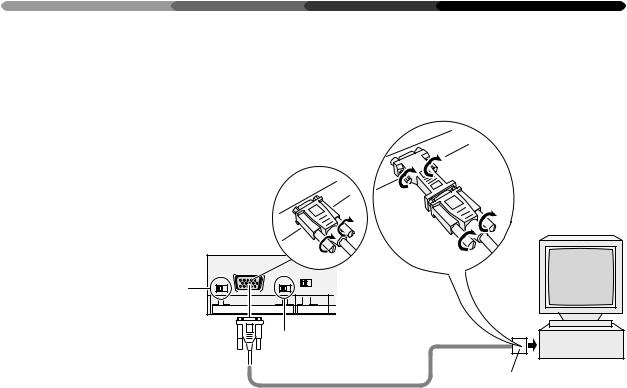
7 In case of a Macintosh, a |
7 Dans le cas d’un ordina- |
computer from the NEC |
teur Macintosh, un ordi- |
PC-9800 series, or a ma- |
nateurdelasérieNECPC- |
chine compatible with |
9800 ou une machine |
one of these computers: |
compatible avec l’un des |
|
ordinateurs suivants: |
•Desk-top type
•Type de bureau
• Desktop
CONNECTIONS
CONNEXIONS
ANSCHLÜSSE
7Macintosh-Computer der NEC PC-9800-Serie oder Geräte, die mit einem dieser Computer kompatibel sind:
Normally be sure to use set to OFF.
En temps normal, assurezvous d’être en position OFF. Für den Normalbetrieb unbedingt auf OFF stellen.
OFF ON |
RGB-2 |
OFF ON |
75 (Ω) 2.2k |
REMOTE |
G ON SYNC |
SYNC |
|
|
|
1 |
|
23
Macintosh:
You can use your Plasma Display together with the computer in the 13-inch mode.
(640 dots × 480 lines / Horizontal scanning frequency: 35.00 kHz / Vertical scanning frequency: 66.67 Hz)
PC-9800:
Normal Mode:
(640 dots × 400 lines/horizontal scanning frequency 24.83 kHz/ vertical scanning frequency 56.42 Hz, or 640 dots × 400 lines/ horizontal scanning frequency 31.5 kHz/vertical scanning frequency 70 Hz)
DOS/V or Windows VGA mode: (640 dots × 480 lines/horizontal scanning frequency 31.47 kHz/ vertical scanning frequency
59.94 Hz)
•This may not be applicable for some models. Refer to the instructionmanualforthecomputerused for details.
1 G on Sync mode selection switch If the images become greenish when an external device is connected to the RGB-2 input terminal, turn ON the G on SYNC mode. Normally set to OFF.
2Computer connecting cable (available on your local market)
3A conversion adapter (available on your lacal market)
Macintosh:
Vous pouvez utiliser votre écran plasma avec l’ordinateur en mode 13 pouces (640 points × 480 lignes/fréquence de balayage horizontale : 35,00 kHz/ fréquence de balayage verticale: 66,67 Hz).
PC-9800:
Mode normal :
(640 points × 400 lignes/ fréquence de balayage horizontal 24,83 kHz/fréquence de balayage vertical 56,42 Hz ou 640 × 400 lignes/fréquence de balayage horizontal 31,5 kHz/ fréquence de balayage vertical (70 Hz).
Mode DOS/V ou Windows VGA: (640 points × 480 lignes/ fréquence de balayage horizontal 31,47 kHz/fréquence de balayage vertical 59,94 kHz).
•Ceci peut ne pas s’appliquer à certains modèles. Se reporter au manuel d’utilisation de l’ordinateur utilisé pour plus de détails.
1 Gsurboutondesélectiondumode Sync
Silesimagesdeviennentverdâtres lorsqu’un dispositif extérieur est raccordéauterminald’entréeRGB- 2, amener G sur le mode SYNC. Normalement,celui-ciestréglésur
OFF (=arrêt).
2 Câble de raccordement à l’ordinateur
(disponible localement)
3Adaptateur de conversion (disponible localement)
Macintosh:
Ihr Plasma-Display kann im 13- Zoll-Betrieb zusammen mit diesem Computer verwendet werden (640 Punkte × 480 Zeilen) / Horizontale Frequenz: 35,00 kHz / Vertikale Frequenz: 66,67 Hz).
PC-9800:
Normalmodus:
(640 Punkte × 400 Zeilen/ horizontale Abtastfrequenz 24,83 kHz/vertikale Abtastfrequenz 56,42 Hz oder 640 Punkte × 400 Z e i l e n / h o r i z o n t a l e Abtastfrequenz 31,5 kHz/vertikale Abtastfrequenz 70 Hz)
DOS/V oder Windows VGAModus:
(640 Punkte × 480 Zeilen/ horizontale Abtastfrequenz 31,47 kHz/vertikale Abtastfrequenz 59,94 Hz)
•Auf einige Modelle mag dies nicht zutreffen. Einzelheiten darüber entnehmen Sie bitte der Bedienungsanweisung des verwendeten Computers.
1 G am SynchronisierungsModuswählschalter
Werden die Bilder grünlich, sobald ein externes Gerät an der InputSchnittstelle von RGB-2- angeschlossen wird, schalten Sie G
am SYNC-Moduswählschalter auf ON (EIN), während es normalerweiseaufOFF(AUS)steht.
2Computeranschlußkabel (erhältlich bei Ihrem Fachhändler)
3Übergangsstecker
(erhältlich bei Ihrem Fachhändler)
23
<ARE1356>
En/Fr/Ge
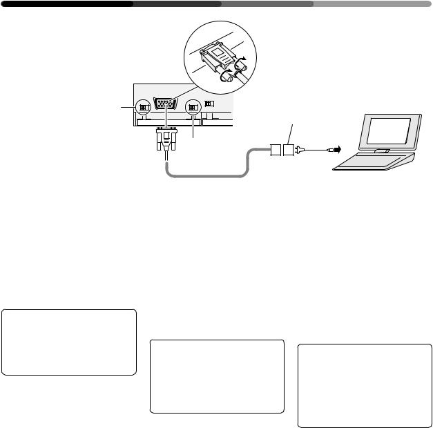
CONNECTIONS CONNEXIONS ANSCHLÜSSE
•Notebook type
•Type bloc-notes
•Notebook
Normally be sure to use set to OFF.
En temps normal, assurezvous d’être en position OFF. Für den Normalbetrieb unbedingt auf OFF stellen.
OFF ON |
RGB-2 |
OFF ON |
75 (Ω) 2.2k |
3 |
REMOTE |
G ON SYNC |
SYNC |
1
2
1G on Sync mode selection switch If the images become greenish when an external device is connected to the RGB-2 input terminal, turn ON the G on SYNC
mode. Normally set to OFF.
2Computer connecting cable (available on your local market)
3A conversion adapter provided with the notebook-type computer. Or available on your local market.
When inserting the cable, be sure to confirm the shape of the signal input terminal of the Display and that of theconnectingcableconnector.After inserting the cable, fix it securely by fastening the side screws.
NOTES:
•Notebook-type personal computers with a built-in LCD panel of VGA display type may have an external RGB output which is non-VGA. In thiscase,imagesarenotreproduced on the main unit. The external RGB output should be set to the VGA mode.
•The computer manufacturers, product names, etc. appearing in this manual are the trademarks or registered trademarks of the respective companies.
•Some Macintosh models output boththeG-on-SYNCand composite SYNC signals, which causes the screen to become greenish. In this case, turn ON the G on SYNC mode switch. Normally be sure to use set to OFF.
24
<ARE1356>
En/Fr/Ge
1Gsurboutondesélectiondumode Sync
Silesimagesdeviennentverdâtres lorsqu’un dispositif extérieur est raccordéauterminald’entréeRGB- 2, amener G sur le mode SYNC. Normalement,celui-ciestréglésur OFF (=arrêt).
2Câble de raccordement à l’ordinateur
(disponible localement)
3Adaptateur de conversion (fourni avec l’ordinateur de type blocnotes, ou disponible localement).
Lors de l’insertion du câble, ne pas oublier de confirmer la forme de la borne d’entrée du signal de l’écran et celle du connecteur du câble de connexion.Aprèsl’insertionducâble, fixer celui-ci en serrant les vis latérales.
NOTES:
•Les ordinateurs personnels du type bloc-notes avec panneau LCD incorporé pour type d’écran VGA peuvent posséder une sortie RGB extérieure qui est non-VGA. Dans ce cas, les images ne seront pas reproduites sur l’écran principal. La sortie RGB extérieure devra être amenée en mode VGA.
•Les constructeurs d’ordinateurs, les noms de produits etc. figurant dans ce manuel sont des marques de commerce ou des marques de commercedéposéesdessociétésen question.
•Certains modèles Macintosh sortent à la fois les signaux G-on- SYNC et SYNC composites, ce qui provoque le verdissement de l”écran. Dans ce cas, actionner G sur l’interrupteur du mode SYNC. Bien s’assurer que la position normale est OFF (=arrêt).
1G am SynchronisierungsModuswählschalter
Werden die Bilder grünlich, sobald ein externes Gerät an der InputSchnittstelle von RGB-2- angeschlossen wird, schalten Sie G am SYNC-Moduswählschalter auf ON (EIN), während es normalerweise auf OFF (AUS)
steht.
2Computeranschlußkabel (erhältlich bei Ihrem Fachhändler)
3Übergangsstecker, zusammen mit dem Notebook-Computer geliefert.SonsterhältlichbeiIhrem Fachhändler.
Wenn Sie das Kabel einstecken, sollten Sie immer die Form des Signal-Eingangskabels des Displays mit der Form des Anschlußkabelsteckers vergleichen. Wenn Sie das Kabel eingesteckt haben, befestigen Sie es sorgfältig mit den zwei seitlichen Schrauben.
Anmerkungen:
•Notebook-Computer mit eingebautem LCD-Bildschirm des VGA-Modells haben manchmal einen externen RGB-Ausgang, der kein VGA-Modell ist. In diesem Fall werden am Hauptgerät keine Bilder wiedergegeben. Der externe RGBAusgang sollte auf VGA-Betrieb eingestellt werden.
•Die in dieser Bedienungsanleitung genannten Computerhersteller, Produktnamen usw. sind Markennamen oder eingetragene Schutzmarken der jeweiligen Unternehmen.
•Einige Macintosh‚-Modelle geben sowohl G-on-SYNC als auch Frequenzgemische (zusammengesetzte Signale) aus, was den Schirm grünlich werden läßt. Schalten Sie in diesem Fall G am SYNC-Moduswählschalter auf ON (EIN), während es normalerweise auf OFF (AUS) stehen muß.
 Loading...