


PDP-V401
Pioneer PDP-V401, PDP-V401E, PDK-4001, PDK-4006, PDK-4002 Technical Manual
...
Plasma Display:
PDP-V401/V401E
Ceiling-suspension metal fixture for plasma display:
PDK-4001 PDK-4006
PDK-4002 PDA-4001
PDK-4003 PDA-4002
PDK-4004 PDP-S01-LR
PDK-4005
[Installation]
¶ We sell this equipment on the assumption that it
will be installed by a specialist with adequate training.
The equipment must be installed by trained vendors
or by your dealer.
¶ We are not responsible for injuries or damage
resulting from choice of unsuitable installation sites,
problems in assembly and installation, improper
installation, or natural disasters.
Note:
• We are not responsible for damage caused by defective
parts supplied by third parties.
• The performance of the equipment is guaranteed only
when assembly and adjustment are performed as
described herein.
• The specifications and descriptions given in this
technical manual are subject to change without notice.
For safety
In this manual, this symbol indicates important
precautions. Read these precautions carefully.
This manual gives precautions, general information, and examples for installation and handling of the plasma display
and its metal fixtures.
Carefully examine the structure, material, strength, and environmental conditions for the site at which the display is to
be installed before selecting an installation method. If the site is unsatisfactory, venders should not sell or install the
equipment.
TECHNICAL MANUAL (ver.2.1)

2
<Ver. 2.1>
Contents
Features ................................................................................................................................................................. 4
Specifications ......................................................................................................................................................... 6
2.1 List of specifications ................................................................................................................................... 6
2.2 Outline drawing ........................................................................................................................................... 7
2.3 Part names .................................................................................................................................................. 8
2.4 Remote control ........................................................................................................................................... 9
Installation ............................................................................................................................................................ 10
3.1 Installation environment ............................................................................................................................ 10
3.2 Installation conditions ............................................................................................................................... 12
3.2.1 Radiation ............................................................................................................................................ 12
3.2.2 Calculating calorific values ................................................................................................................. 12
3.2.3 Installation position ............................................................................................................................ 13
3.2.4 Strain on surface where equipment is installed................................................................................. 15
3.3 Installation procedure ................................................................................................................................ 16
3.3.1 Precautions for transportation ........................................................................................................... 16
3.3.2 Unpacking .......................................................................................................................................... 16
3.3.3 Wiring ................................................................................................................................................ 18
3.4 Special installations ................................................................................................................................... 20
3.4.1 Fixing on a structure .......................................................................................................................... 20
3.4.2 Wall hanging ...................................................................................................................................... 22
3.4.3 Wall embedding ................................................................................................................................. 24
3.4.4 Ceiling suspension (using wires) ....................................................................................................... 28
3.4.5 Installation with the screen downward.............................................................................................. 30
3.4.6 Ceiling embedding ............................................................................................................................. 32
3.4.7 Installation on the floor ...................................................................................................................... 36
3.4.8 Installation under the floor ................................................................................................................. 38
3.4.9 Installation under the floor (using the PDM-4001) ............................................................................. 42
3.4.10 Wall hanging (vertically wall-hanging equipment) .............................................................................. 44
3.4.11 Wall embedding (vertically wall-embedding equipment) ................................................................... 46
3.4.12 Horizontal connections ...................................................................................................................... 50
3.4.13 Vertical connections........................................................................................................................... 54
Mounting standard metal fixtures ..................................................................................................................... 56
4.1 Functions and features of standard metal fixtures ................................................................................... 56
4.2 Handling standard metal fixtures .............................................................................................................. 57
4.2.1 Precautions on handling metal fixtures.............................................................................................. 57
4.2.2 Precautions for vendors performing the installation .......................................................................... 57
4.3 Stand (an accessory to PDP-V401 <PDP-V401E>) .................................................................................... 58
4.3.1 Installing the stand............................................................................................................................. 58
4.3.2 Outer-dimentions diagram ................................................................................................................. 59
4.4 Tilting stand: PDK-4001 ............................................................................................................................. 60
4.4.1 Specifications..................................................................................................................................... 60
4.4.2 Assembling and installing the metal fixture and mounting the plasma display ................................. 61
4.5 One-sided, ceiling-suspension metal fixture for the plasma display: PDK-4002 ....................................... 64
4.5.1 Specifications..................................................................................................................................... 64
4.5.2 Assembling and installing the metal fixture and mounting the plasma display ................................. 66
4.6 Double-sided, ceiling-suspension metal fixture for the plasma display: PDK-4003 .................................. 70
4.6.1 Specifications..................................................................................................................................... 70
4.6.2 Assembling and installing the metal fixture and mounting the plasma display ................................. 71
4.7 Ceiling-suspension metal fixture for the plasma display (head screw type): PDK-4004 ........................... 72
4.7.1 Specifications..................................................................................................................................... 72
4.7.2 Assembling and installing the metal fixture and mounting the plasma display ................................. 73
4.8 PDP bracket: PDK-4005 ............................................................................................................................ 76
4.8.1 Specifications..................................................................................................................................... 76
4.8.2 Assembling and installing the metal fixture and mounting the plasma display ................................. 77
4.9 Wall hanging metal fixture for the plasma display: PDK-4006 ..................................................................82
4.9.1 Specifications..................................................................................................................................... 82
4.9.2 Assembling and installing the metal fixture and mounting the plasma display ................................. 83
3
<Ver. 2.1>
Warning
• To prevent damage or injury, carefully read and follow this manual and all labels provided on the main display
body before undertaking assembly, installation, movement, or adjustment.
• To prevent fire and electric shock resulting from moisture infiltration, never use this system outdoors.
• To prevent injury, take care when handling the system's sharp edges.
• When installing the system at a height, create an off-limits zone to prevent injury or secondary damage in case of
falling equipment.
• To prevent fire and electric shock, never place foreign objects within or make modifications to the equipment.
• Always observe the following operating environmental conditions:
Temperature : 0 °C to 40 °C
Humidity : Relative humidity 20% to 80%
• Make sure the site is well-ventilated, and take care to maintain adequate ventilation following installation.
4.10Infrared reduction filter: PDA-4001, protective filter: PDA-4002 .............................................................. 90
4.10.1 Specifications and features (infrared reduction filter: PDA-4001) ...................................................... 90
4.10.2 Specifications and features (protective filter: PDA-4002) .................................................................. 91
4.10.3 Assembling and installing the metal fixture and mounting the plasma display ................................. 92
4.10.4 White balance .................................................................................................................................... 95
4.10.5 Mounting the PDP bracket: PDK-4005, with PDA-4001 and PDA-4002 mounted ............................. 95
4.
11
Speaker system: PDP-S01-LR ................................................................................................................ 96
4.11.1 Before operation ................................................................................................................................ 96
4.11.2 Specifications ..................................................................................................................................... 96
4.11.3 Assembling and installing the metal fixture and mounting the plasma display ................................. 97
4.11.4 Precautions for mounting different metal fixtures after the optional speakers are attached
to the plasma display main body ..................................................................................................... 100
Adjustment ......................................................................................................................................................... 106
5.1 Before making adjustments ................................................................................................................... 106
5.1.1 Operation mode ............................................................................................................................... 106
5.1.2 Picture quality and white-balance adjustment memory ................................................................... 110
5.1.3 Phase-adjustment memory.............................................................................................................. 111
5.1.4 Using the plasma display main body and the remote control together with the personal control ....... 111
5.1.5 Last memory.................................................................................................................................... 112
5.1.6 Aging................................................................................................................................................ 113
5.2 Performing adjustments on the plasma display operation panel and remote control ............................ 114
5.2.1 Menu mode ..................................................................................................................................... 114
5.2.2 Integrator mode ............................................................................................................................... 118
5.2.3 Precautions ...................................................................................................................................... 125
5.3 Outer control by RS232C........................................................................................................................ 126
5.3.1 Precautions ...................................................................................................................................... 126
5.3.2 Interface........................................................................................................................................... 127
5.3.3 RS232C commands table ................................................................................................................ 128
5.3.4 List of GET commands .................................................................................................................... 130
Precautions for functions and operation ......................................................................................................... 132
6.1 KEY LOCK/UNLOCK ............................................................................................................................... 132
6.1.1 Functions ......................................................................................................................................... 132
6.1.2 Setting method ................................................................................................................................ 132
6.2 Mask color select/off when NTSC is input ............................................................................................. 133
6.2.1 Functions ......................................................................................................................................... 133
6.2.2 Setting method ................................................................................................................................ 133
6.2.3 Precautions ...................................................................................................................................... 133
6.3 Mask color select when PC-9800
®
is input ............................................................................................ 134
6.3.1 Functions ......................................................................................................................................... 134
6.3.2 Setting method ................................................................................................................................ 134
6.3.3 Precautions ...................................................................................................................................... 134
6.4 Pseudo-contour ...................................................................................................................................... 134
6.5 Precautions ............................................................................................................................................. 135
Maintenance ...................................................................................................................................................... 136
Contents

4
<Ver. 2.1>
Features
Features and functions of the plasma display (PDP-V401/V401E)
¶ Materialization of high luminance (400 cd/m2)
Industry-leading luminance, equal to that of 30-inch class CRTs, is achieved by optimizing panel cell-structure.
¶ Sharp picture quality
Eight-bit (256-color) and full-color (16,770,000 colors) display, with Pioneer's unique pseudo-contour-reducing
technology that reduces plasma display noise.
¶ Thin and lightweight: 88 mm in depth and 30.8 kg in weight
Industry-leading compactness, 88 mm deep and 30.8 kg <31.6 kg> in weight, permits installation in places inappropriate
for ordinary displays.
< > shows the PDP-V401E.
¶ Best display for industrial and public purposes
Our plasma display (PDP-V401/V401E) is specifically designed for use as an industrial display. It has been designed
to provide the following features:
• An aspect ratio of 4:3 optimal for use as a public display
• A versatile mounting structure and metal fixtures permitting wall or vertical installation
• Integrator mode that enables fine adjustment
• Equipped with an RS232C serial connection port as an external control interface
• Other functions, including color temperature setting to allow retakes and a key lock to prevent tampering
Our plasma display has been designed for durability and reliability, features required in industrial displays. Its features
and quality allow use in a wide range of applications and locations.

5
<Ver. 2.1>
Features

6
<Ver. 2.1>
List of specifications
Applicable sources
1 Video system: NTSC <PAL/NTSC Dual>
2 Computer system
1.Resolution
AT-compatible: VGA (640 dots × 480 lines)
Macintosh
®
: 13-inch mode (640 dots × 480 line)
PC-9800
®
: Normal mode (640 dots × 400 line)
2.Synchronizing frequency:
AT-compatible: 31.5 kHz (horizontal), 60 Hz (vertical)
Macintosh
®
: 35 kHz (horizontal), 67 Hz (vertical)
PC-9800
®
: 24.8 kHz (horizontal), 56 Hz (vertical)
31.5 kHz (horizontal), 70 Hz (vertical)
Does not accommodate the interlaced mode of the computer.
Some types of computer have multiple indication modes.
However, some modes cannot be displayed even if the computer
meets the specifications. Please contact your dealer for further
information.
Power source ...................... 100 to 120 V AC, 50/60 Hz
<220 to 240 V AC , 50/60 Hz>
Inrush ................................ 70 A or less <30 A or less>
Power factor ............................................ 0.95 or more
Power consumption .............. 350 W (in standby: 2 W)
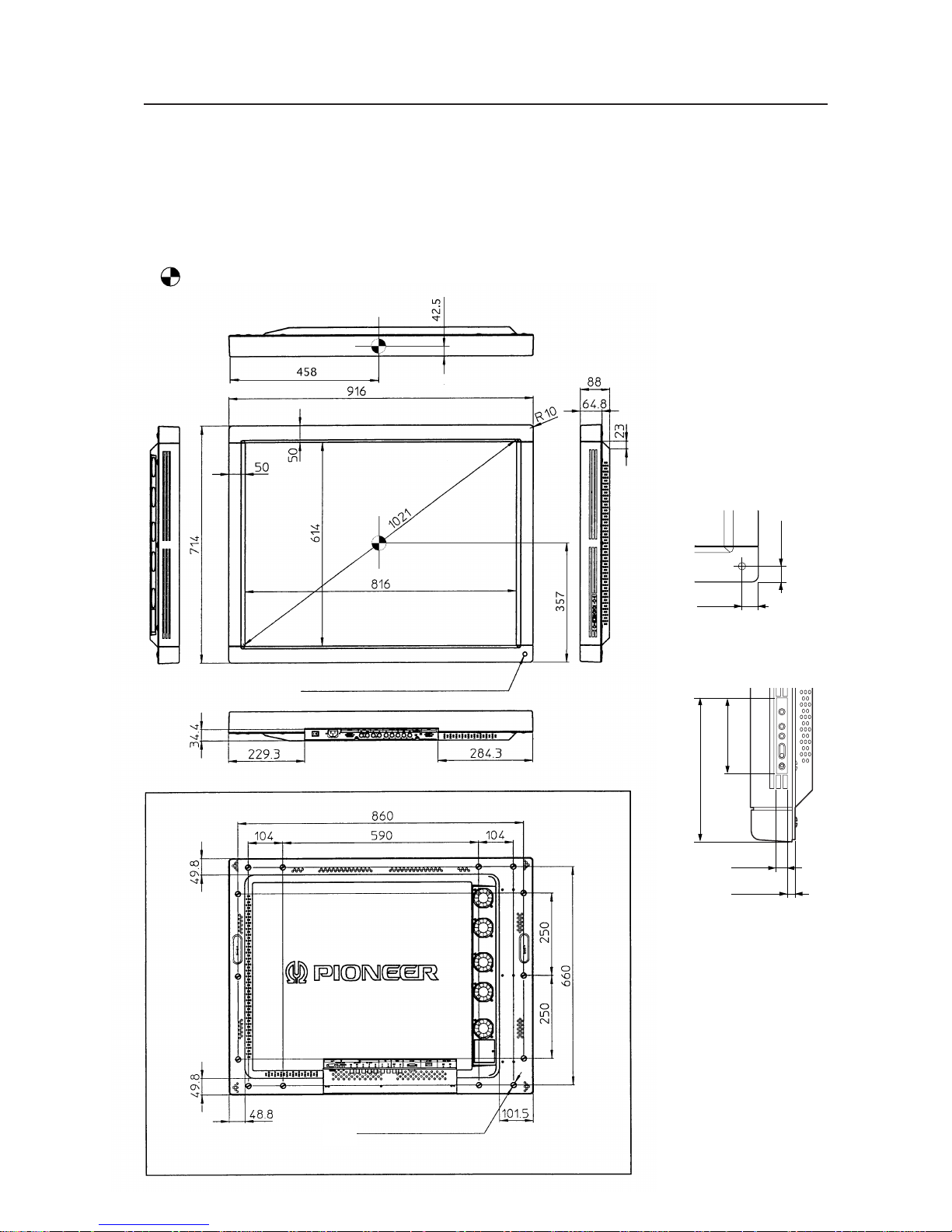
Outer dimensions........ 916 (W) × 714 (H) × 88 (D) mm
Weight .............................................. 30.8 kg <31.6 kg>
Operating environment temperature range
..................................................................... 0 to 40 °C
Operating environment humidity range
.................................... Relative humidity 20% to 80%
Operating environment air pressure range
.................................... 0.8 - 1.1 atmospheric pressure
Storage conditions (Package state)
Storage environment temperature range
............................................................ –10 to 45 °C
Storage environment humidity range
............................... Relative humidity 20% to 90%
Storage stack limit ............................ maximum of 10
Accessory
Power cord (PDP-V401 only) ........................................ 1
Remote control ............................................................ 1
AA battery .................................................................... 2
Stand ............................................................................ 2
Bolt ............................................................................... 2
Washer ......................................................................... 2
Cable clamp.................................................................. 3
Operating Instructions.................................................. 1
• Specifications and appearance are subject to change
without notice.
• < > shows the PDP-V401E.
2.1 List of specifications
Light emission panel...... 40-inch plasma display panel
Aspect ratio ............................................................. 4:3
No. of pixels ................... 640 × 480 (adaptable to VGA)
Pixel pitch
........... 1.26 (horizontal, RGB trio) × 1.26 (vertical) mm
No. of gradations ................................ 256 gradations/
16,770,000-color full color
Luminance ............................... 400 cd/m
2
(panel alone)
View angle ............................ Horizontal : 160° or more
Vertical : 160° or more
Input/output terminals
RGB Input
1 BNC Terminal R, G, B (fixed to 75 Ω input)
HD (H/V SYNC), VD (switching between 75 Ω /2.2 kΩ
input)
Switch VD according to the sync output impedance
of the connector. Switch VD to 2.2 kΩ except when
the sync output impedance is 75 Ω. (The terminal is
factory-set to 75 Ω.)
2 Mini Dsub 15P
Analog RGB, 0.7 Vp-p, 75 Ω input, G-on Sync input
(Sync 0 - 3 Vp-p)
Synchronization:
HD, VD 2.2 kΩ input, 2.0 - 5.0 Vp-p (Positive/Negative),
G-on Sync switch (G-on Sync ON/OFF Change over)
Turn the switch on only if images become greenish
(when the G-on Sync signal is applied) at RGB2 input.
Under normal circumstances, the switch is left off.
(The switch is factory-set to G-on Sync OFF.)
Video input ...... Single-system BNC terminal 75 Ω input
Composite 1 Vp-p
Y/C input .......... Double-system BNC terminal 75 Ω input
Control input.... Dsub 9P (RS232C control)
Video output .... Single-system BNC terminal 75 Ω output
(Note: Up to four units, including the unit
to which the signal is first input, may be
connected when the equipment is
connected in series using this output
terminal. However, increasing the
number of connected units may increase
the noise.)
7
<Ver. 2.1>
Outline drawing
φ12
(the opening for infrared remote control signals)
14-M8 (with φ16-hole rivet)
Rear View
2.2 Outline drawing
Plasma display main body weight : 30.8 kg <31.6 kg>
Material : Front - Plastic, Back - plate
Treatment : Front - Leather satin gray paint, Back - Semi-matte black paint
Packing specifications - See “3.3.2 Unpacking”
• < > shows the PDP-V401E.
: Location of center of gravity
<Light-accepting section
of the remote controller>
<Operation panel
of the main body>
24
24
202.5
107
14
14.8
8
<Ver. 2.1>
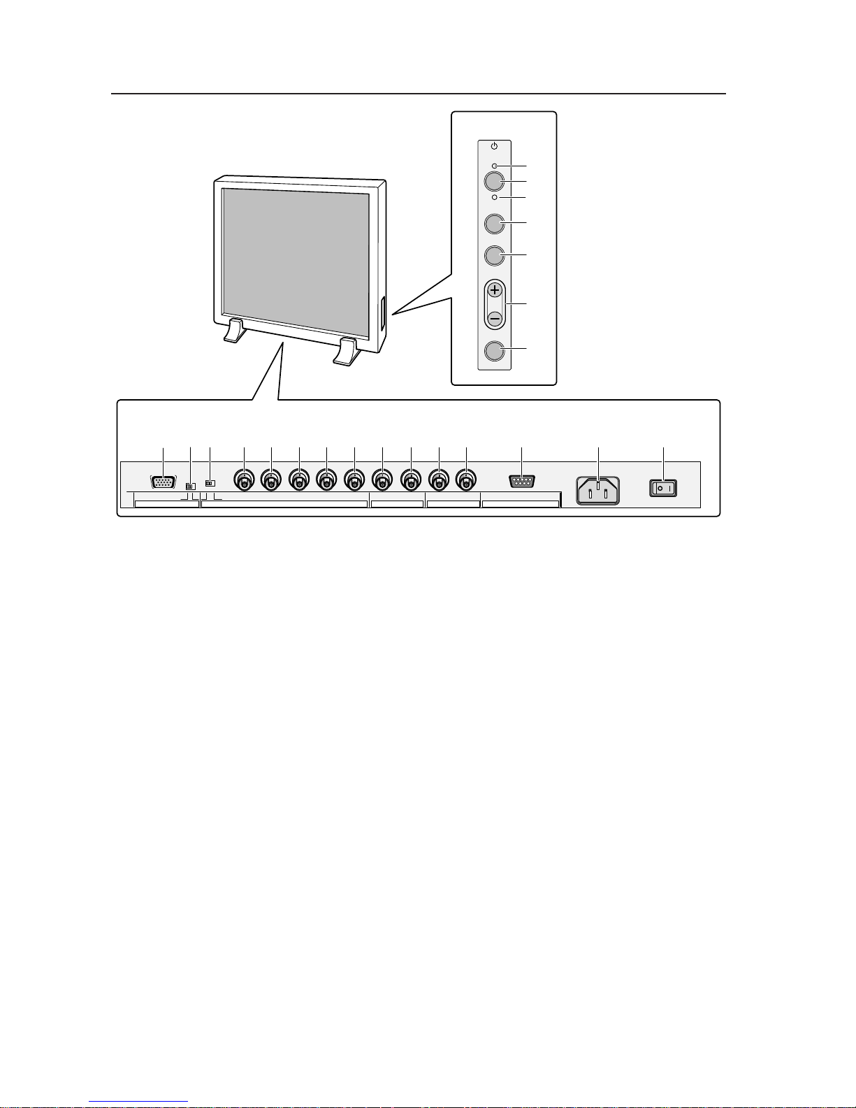
2.3 Part names
Part names
<Operation panel>
1 STANDBY/ON indicator
The switch lights in RED for STANDBY and GREEN for
ON mode.
2 Power button
Turns power on or off.
3 INPUT select button
Selects input.
4 MENU button
Used to switch the menu screen and normal screen.
5 ADJUST button
Used for picture adjustment.
6 SET button
Used to select a selected adjustment item during
picture adjustment.
<Terminals and power supply section>
RGB-2 input terminals
7 Mini D-SUB15 pin terminal
8 G-on SYNC mode select switch (ON/OFF)
If pictures take on a greenish cast when other
external equipment is connected to the RGB-2 input
terminal, turn on the G-on SYNC mode. Normally,
this switch is left off.
RGB-1 input terminals
9 Synchronizing signal input impedance select switch
(75 Ω /2.2 kΩ)
0 Vertical synchronizing signal input terminal:
Switching between 75 Ω /2.2 kΩ)
- Horizontal or composite synchronizing signal input
terminal: Switching between 75 Ω /2.2 kΩ
= Blue signal input terminal: 75 Ω
~ Green signal or synchronizing (ON SYNC) green
signal input terminal: 75 Ω
! Red signal input terminal: 75 Ω
Y/C input terminal
@ Color signal input terminal: 75 Ω
# Luminance signal input terminal: 75 Ω
VIDEO input/output terminal
$ Video output terminal: 75 Ω
(Note: Up to four units including the unit to which
the signal is first input may be connected when the
equipment is connected in series using this output
terminal. However, increasing the number of
connected units may increase noise.)
% Video input terminal: 75 Ω
^ Control signal input terminal (RS232C)
& AC INLET
* Main power switch
( KEY LOCK/UNLOCK button (hidden switch)
Use this button to disable or enable control through
the operation panel or by remote control.
STANDBY
/ON
INPUT
MENU
ADJUST
SET
VD HD B G R C Y OUT IN
75 2.2k
OFF ON
(Ω)
(H/V SYNC) RGB-1 (ON SYNC) Y/C
SYNCG ON SYNC
VIDEO RS-232CRGB-2
1
2
3
4
5
6
7
809-=~!@#$%^ *&
˚(
<Operation Panel>
<Terminals and power supply section>
(The terminals and power supply section are located at the back of the plasma display main body.)
9
<Ver. 2.1>
Y/C button
Sets Input Function to Y/C input.
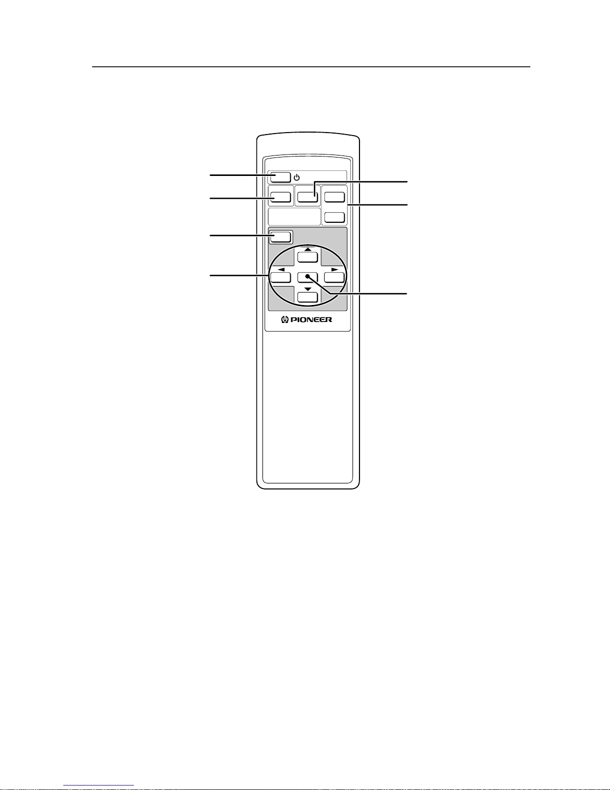
2.4 Remote control
Remote control
SET button
This button used to select an
adjustment item for picture
adjustment.
STANDBY/ON
VIDEO Y/C
SET
MENU
RGB 1
RGB 2
INPUT
SELECT
Î
CU-V153
RGB 1 and 2 buttons
These buttons set Input
Functions to RGB 1 (BNC
terminal) and RGB 2 (Mini DSUB terminal), respectively.
ADJUST button
Used to adjust images.
MENU button
Used to switch the menu
screen and normal screen.
VIDEO button
Sets Input Function to VIDEO
Input.
Power button
Turns power on or off.
10
<Ver. 2.1>
3.1 Installation environment
The plasma display and special metal fixture must be installed after careful discussion with the building owner and
manager of the building. Never undertake installation without careful consideration of the consequences. In addition,
contact the contractor responsible for building construction and interior structure design and confirm the structure and
safety of the building.
: Safety precautions
1) Structure of installation site
Be sure to use an appropriate installation method, after fully understanding the structure of the installation site.
There are many types of building structures and materials, and appropriate installation methods will vary accordingly.
When using a special metal mounting fixture, consult your dealer or the maker of the fixture.
Before drilling holes, always consider the location of wiring and piping within the building.
2) Load resistance of the installation site
Select an installation site capable of supporting the combined weight of the metal fixture and display.
“Sufficient strength to withstand” means sufficient strength to withstand a weight four times that of the
main body including the metal fixture.
3) Horizontal plane
Select a level, sturdy, installation site with sufficient load-bearing capacity.
When using suspension bolts, take care to distribute load evenly on the ceiling on the floor of the installation site.
4) Securing installation space
Select an installation site with adequate space for working. This work requires two or more people.
Remember to leave adequate space for future maintenance.
5) Peripheral equipment
Installation sites close to air conditioner outlets or light bulbs may be unsuitable due to potential damage from
dust, temperature, humidity, or condensation.
6) Dangerous location sites
Do not install the display at locations where it may be leaned against or grasped. Similarly, avoid installing at sites
subject to excessive vibration or physical shock.
7) Lighting
• For more visible display, avoid installation in very bright locations. Before choosing the location site and
method,carefully consider the location of lighting fixtures and direction and strength of sunlight.
• In bright locations, images may appear dark even if the luminance is increased. Adjusting picture brightness to
excessively high levels to compensate for extremely bright ambient lighting may reduce the service life of the
display panel.
8) Semi-outdoor installation
This machine is designed for indoor use. Installed semi-outdoors, the display will be subject to problems resulting
involving the following factors:
• Water, dust, etc.
• Changing temperature and humidity
• Air-borne salt
To ensure that pictures appear normal, avoid installation in locations subject to direct sunlight.
Installation environment

11
<Ver. 2.1>
9) Temperature and humidity
The installation site should conform to the following temperature and humidity conditions:
• Operating temperature range: 0 to 40 °C (Depending somewhat on installation conditions, see descriptions of
special installations and methods for installation of the standard metal fixture.)
• Operating humidity range: relative humidity 20% to 80%
• Storage temperature (Packege state): –10 to 45 °C
• Storage humidity (Packege state): relative humidity 20% to 90%
• Operating environment air pressure: 0.8 - 1.1 atmospheres
We recommend against installing electronic equipment, including this display, in high-humidity environments. If
the display must be installed at a site subject to humid conditions, observe the following:
• Never install the machine in environments having humidity falling outside the specification range.
• Ground the equipment.
• Do not allow condensation to form on any display surface.
10) Condensation
One common problem encountered during winter is condensation, drops of water that form on display surfaces
when the ambient temperature rises suddenly. Such moisture may adversely affect the performance of the display.
If condensation is observed, turn off the machine for one hour before attempting to use it again. Another solution
is to raise the ambient temperature gradually, if possible.
11) Power requirements
The voltage range required to ensure specified performance is ±10% of the rated voltage. Keep in mind that high-
impedance power distributing wires will produce an effect equivalent to a voltage drop. Watch for the following
cases, and recheck power distribution.
• The voltage drop between the switchboard and the plasma display is significant.
• When the power to the machine is turned on and off, voltage fluctuations are large.
Estimate the power consumption of this machine as 400 VA plus a safety margin.
The inrush current when the machine is turned on is approximately 70 A <30 A>.
< > shows the PDP-V401E.
12) Coverage of the remote control
The display communicates with the remote control through weak infrared signals, which typically reflect off display
surroundings. The operating range of the remote is affected by the reflective characteristics of surrounding objects.
If the range of coverage appears to be unusually short, check the following:
• Do the walls and platform for the display have a mirror or white finish?
• Are there objects near the infrared-accepting section?
• Are the remote control batteries weak or dead?
Other devices using infrared remote control and wireless systems may not work properly if located close to the
infrared-emission source of the display. Consult your dealer before using such equipment near the display.
Installation environment
12
<Ver. 2.1>
Installation conditions
3.2.2 Calculating calorific values
Estimate the maximum power consumption per device as 400 W plus a safety margin. Most of the power consumed
is converted to heat, so power consumption is roughly equivalent to generated heat.
1) Conversion to calories
[W] × 0.86 = [kcal/h]
Calorific value per display
400 × 0.86 = 344 [kcal/h]
2) Conversion to British thermal unit (BTU)
[W] × 3.41 = [B.t.u./h]
Calorific value per display
400 × 3.41 = 1256 [B.t.u./h]
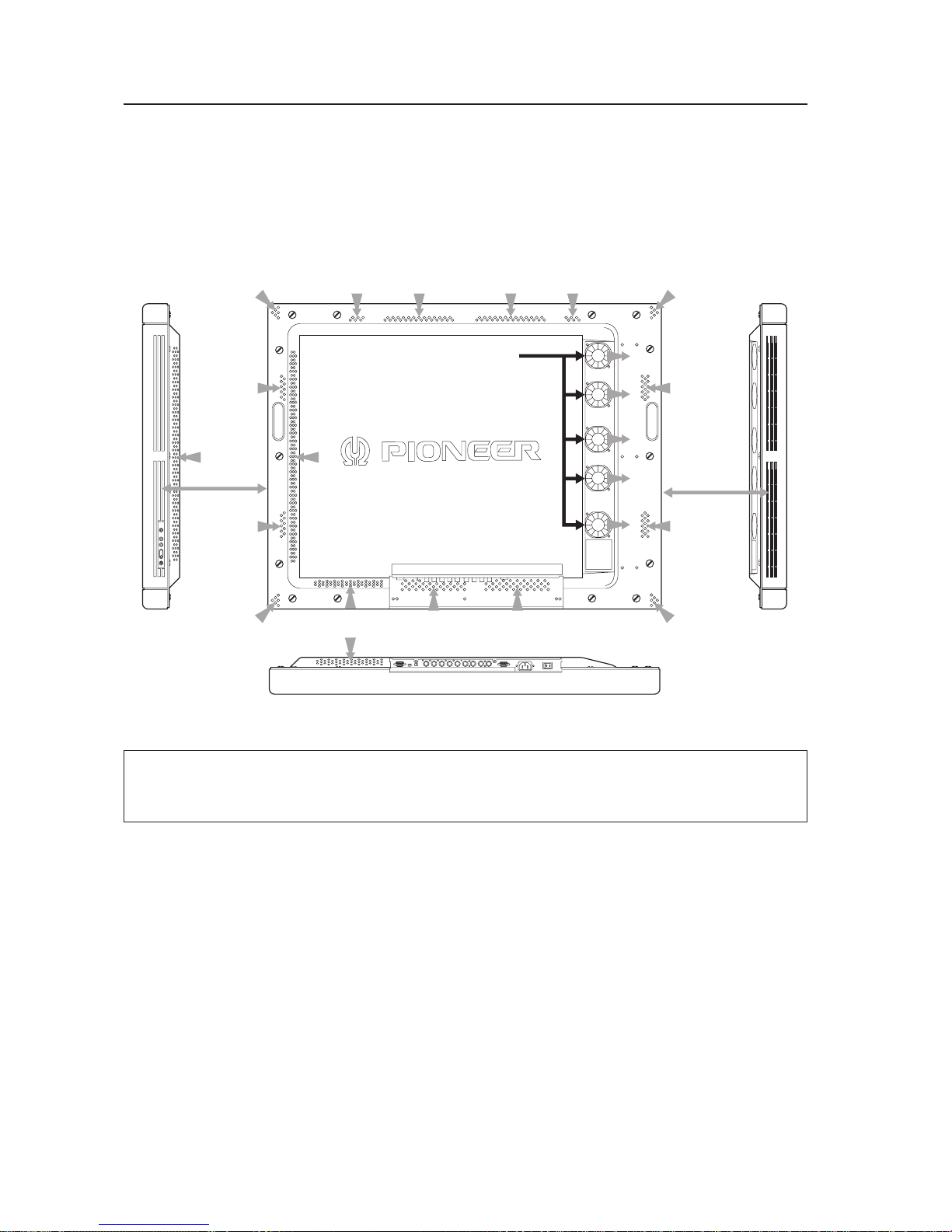
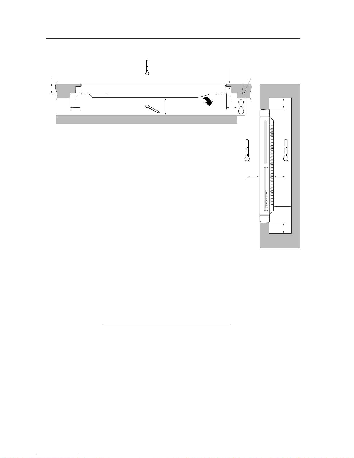
Air flows out through five of the ventilation holes and flows in through the other holes. For special installations, such
as wall-hanging or embedding, additional restrictions apply concerning operating temperature. See “3.4 Special
installations”.
3.2 Installation conditions
3.2.1 Radiation
This display comes with multiple ventilation holes for efficient radiation of heat. Avoid blocking any of these holes.
Ventilation holes are indicated by arrows in the following drawing.
Five fans
Side slits
Side slits
13
<Ver. 2.1>
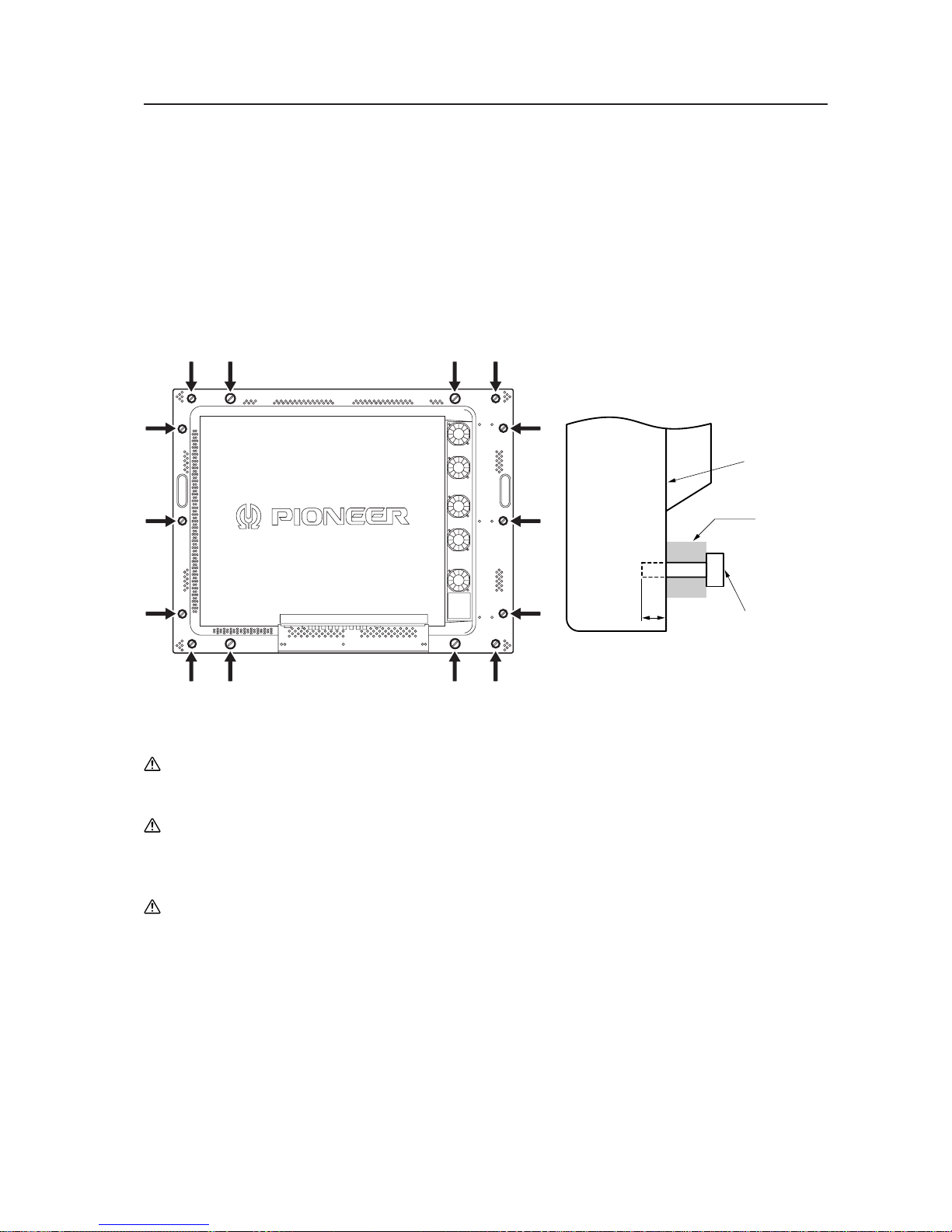
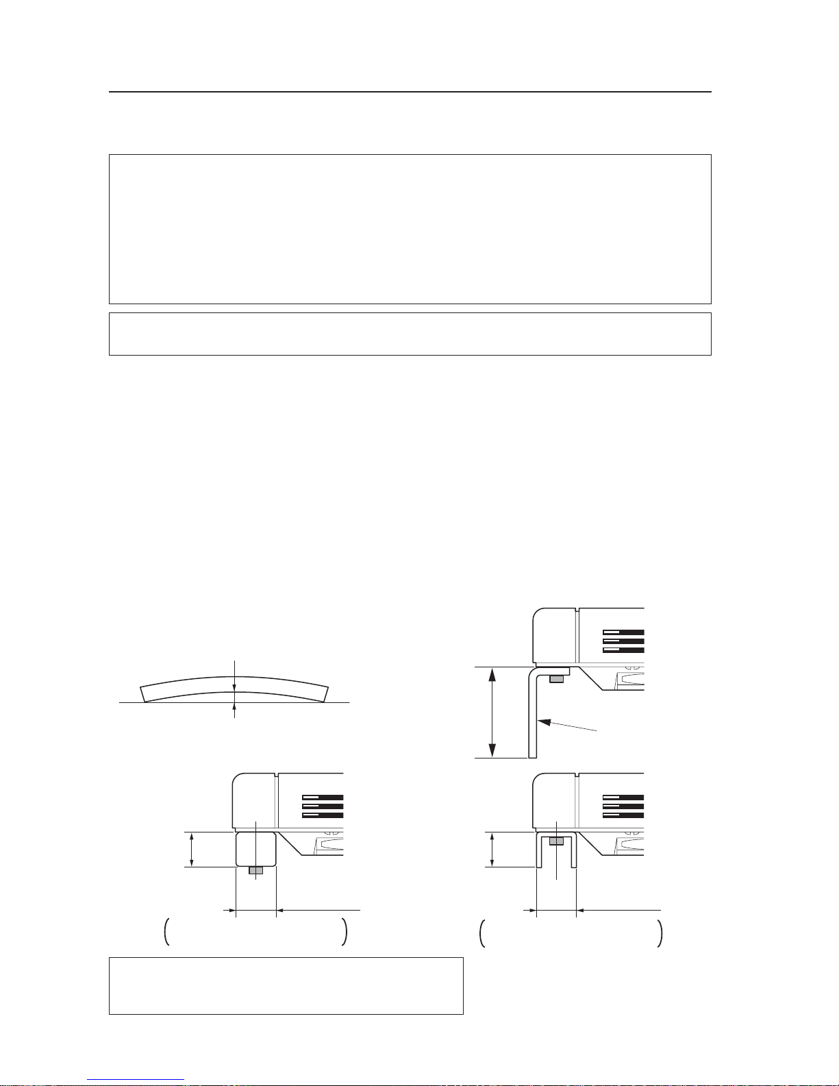
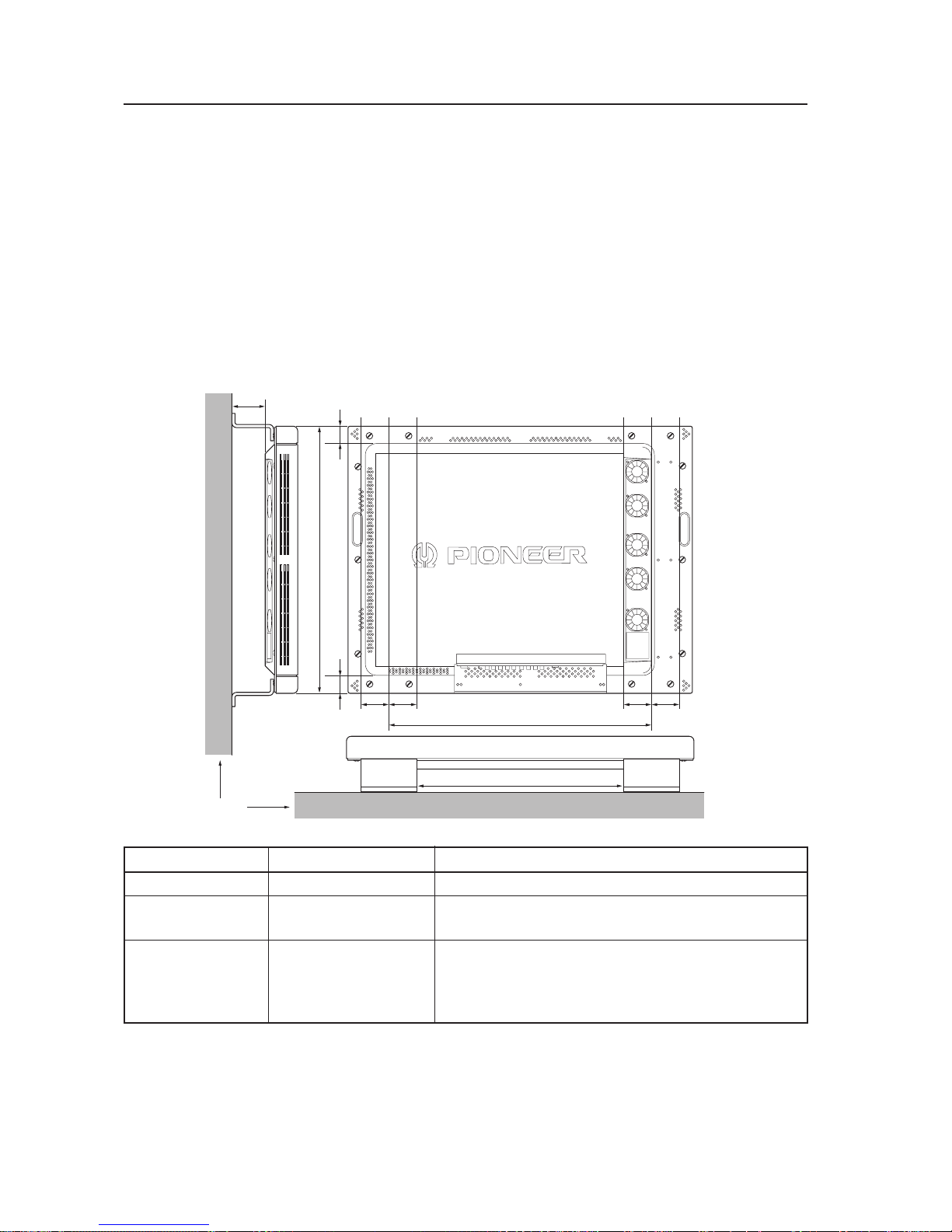
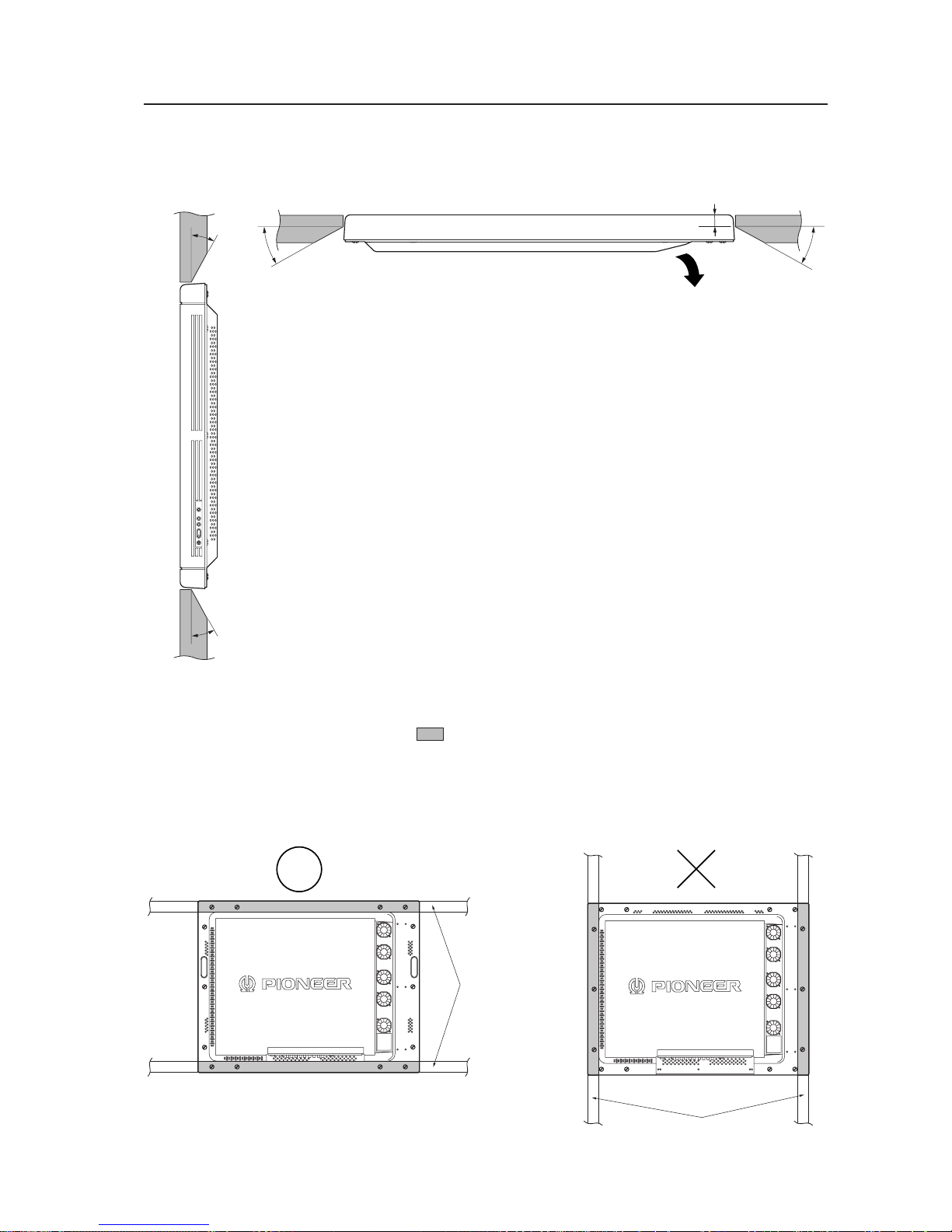
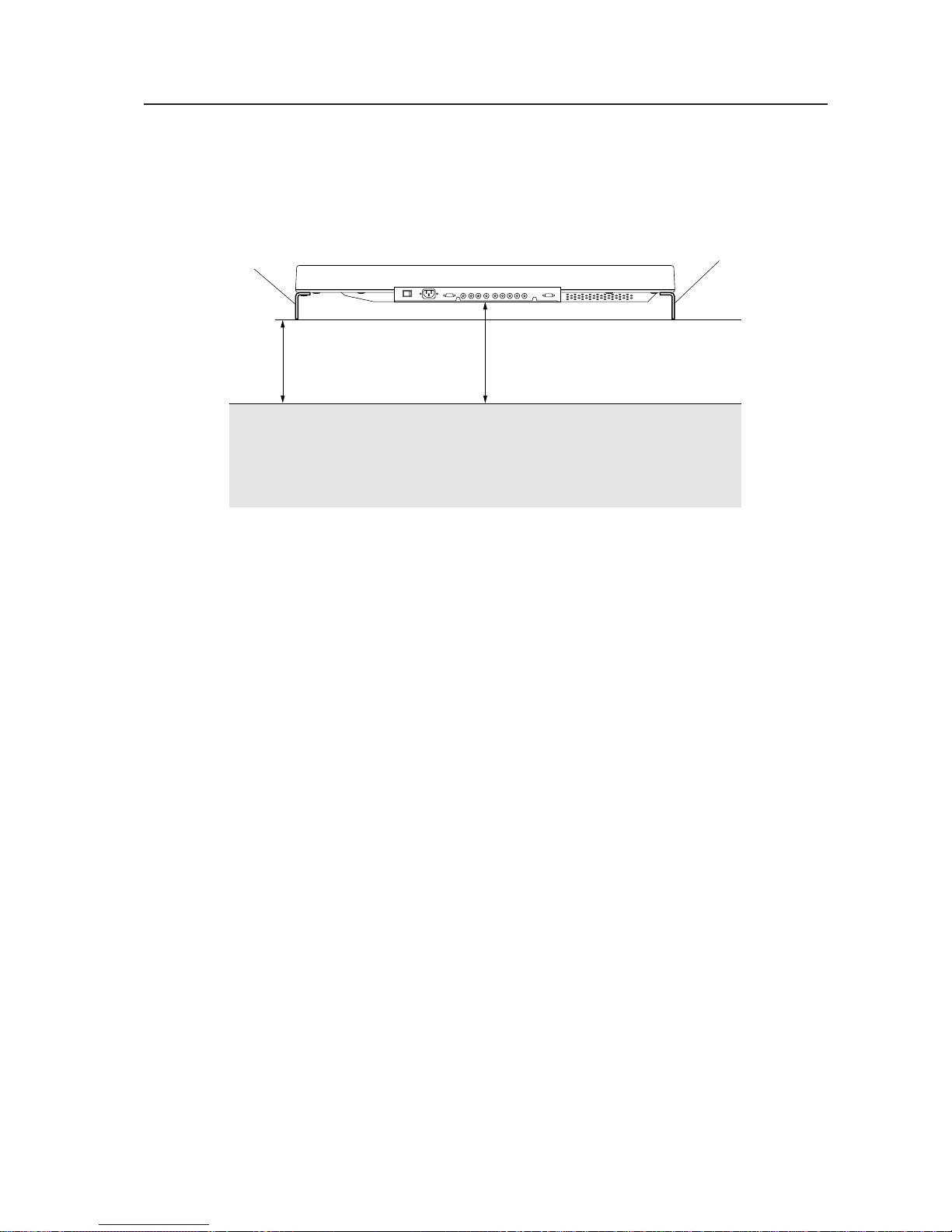
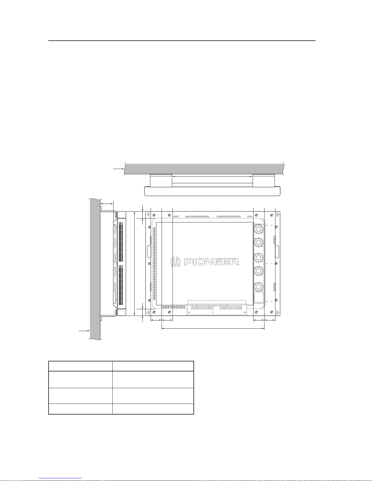
3.2.3 Installation position
We recommend using the metal installation fixture made by Pioneer. When using a different fixture, use the M8 bolt
hole provided on this display to mount the fixture to the display. Remove the hole rivets on the back of the plasma
display, if necessary for the particular fixture. Tighten bolts with a force of 60 kg.cm or less. Overtightening may
damage the blind nuts.
• The following figure indicates mounting holes that can be used. (Use a coin or similar object to turn the cap to
remove it.)
Installation conditions
Use bolts that do not penetrate more than 13 to 20 mm from the mounting surface of the machine (see the above
side view). If the bolts used are longer than the above, they may damage the inside of the machine.
Do not block ventilating holes or blowholes in the rear of the machine.
Hot air is emitted from the ventilating holes.
Care must be taken not to weaken or soil the wall at the back of the machine with the hot air from the holes.
Glass is used in this machine. It must always be mounted on the straight face.
Mounting surface
Metal fixture
13 to 20 mm
Bolt

14
<Ver. 2.1>
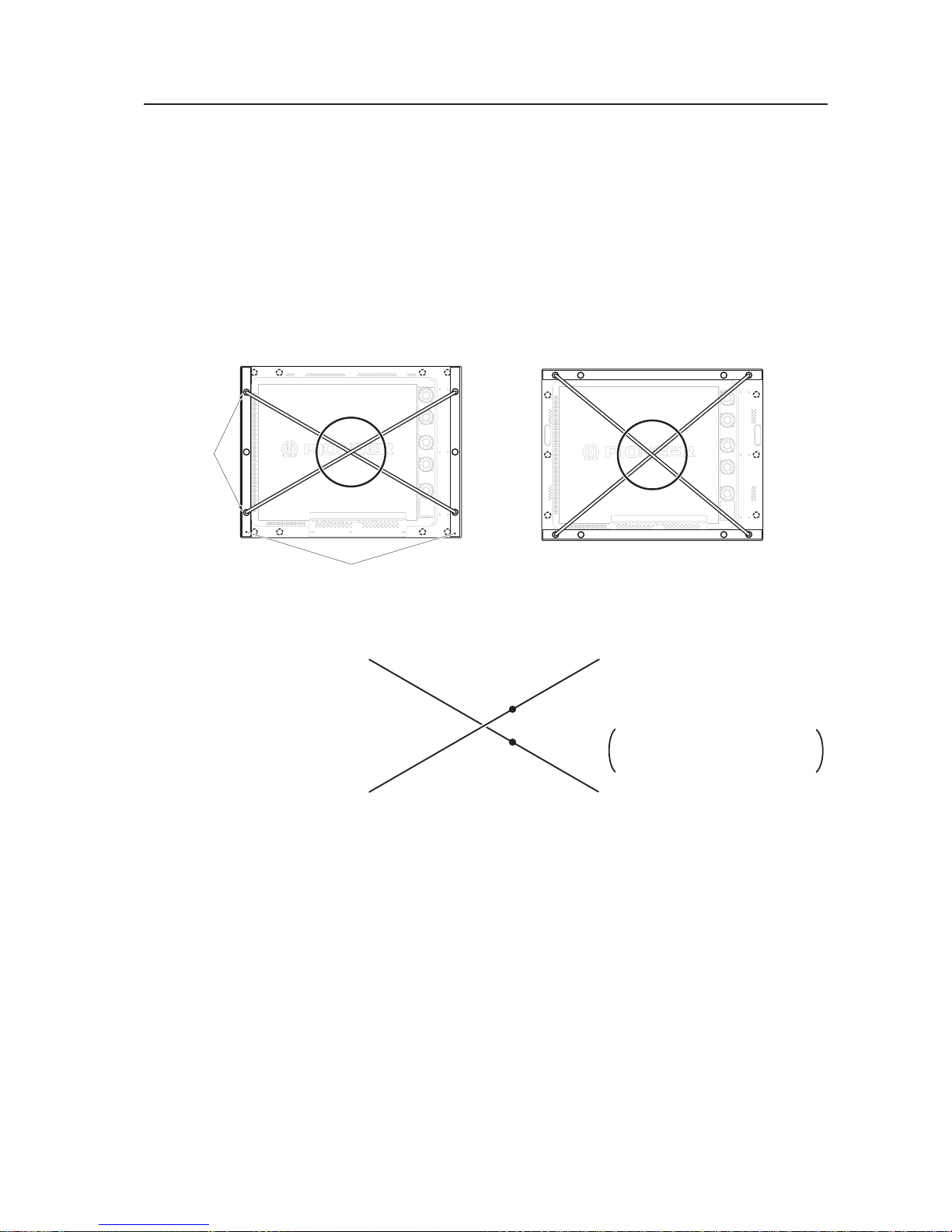
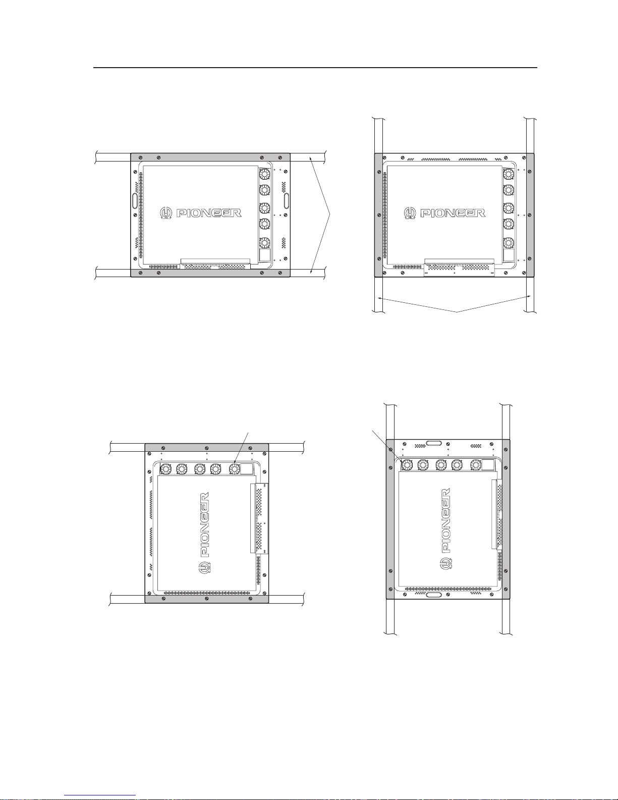
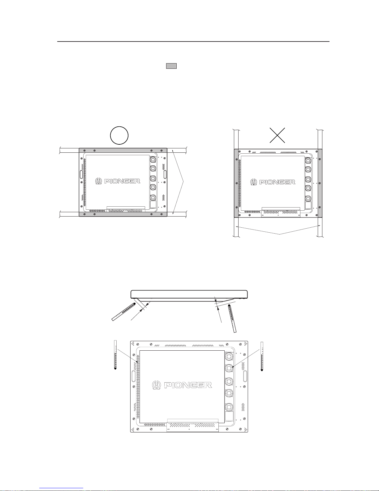
We recommend mounting at a minimum of 4 points, and at 6 or 8 points as shown below if possible. Avoid mounting
the display with the particular 4-point scheme shown below.
Mounting method — bad example
Mounting method — good example
A. 8-point mounting B. 6-point mounting
C. 4-point mounting (Metal fixture is mounted vertically.)
(Do not block ventilation holes.)
Installation conditions
(Do not block ventilation holes.) (Do not block the fan.)
D. 4-point mounting (Metal fixture is mounted horizontally.)
(Take care to avoid pinching power cord, signal cable, etc.)
15
<Ver. 2.1>
A
Installation conditions
3.2.4 Strain on surface where equipment is installed
1 This display uses glass in its display section. When using a third-party metal fixture, check that strain is 1 mm or
less by the following method.
2 Tightly fit a thread using a force of φ 0.1psi or less diagonally through the mounting bolt openings on the mounting
surface, as shown in the drawing.
3 Measure distance L of the intersection of the strings in the center section.
The relationship between strain and L is given by Strain = L × 2.
4 If L is 0, interchange the front and rear positions of two strings and check the distance again. If the value of L is not
0, it is the true value of L. If L is 0 after the position is changed, strain is approximately 0.
Holes for
mounting
bolts
Plasma display-mounting surface
(mounting metal fixture)
Enlarged drawing of the intersectional part A
(showing the part obliquely)
Thread
Right angle
A
ad
cb
a
c
d
b
a
d
e
f
cb
Point e is the center of the thread a-b.
Point f is the center of the thread c-d.
Distance between e and f = L
Points e and f are indicated in an en-
larged figure for more detailed under-
standing.
Thread
16
<Ver. 2.1>
3.3 Installation procedure
3.3.1 Precautions for transportation
1 Use two workers to move packages. Do not grasp the PP band during transportation. The band may snap and
result in injury.
2 For transportation and storage, keep the package horizontal. Do not stack packages longitudinally or laterally. If
packages are transported or stored while longitudinally stacked or laterally stacked, the company is guarantee will
be invalidated.
3 For transportation and storage, never stack more than ten packages, as indicated on the upper carton.
4 For transportation and storage, observe the conditions detailed on the upper carton.
5 To protect the glass surface of the display, avoid stepping on the package, placing heavy items on top, or sticking
sharp objects into the top.
* If the plasma display and fixture needs to be packed and transported again, follow the packing method and
precautions given below:
• Pack goods by reversing the procedure for unpacking given in “3.3.2 Unpacking”. Take care when replacing the
mirror mat to place the smooth face facing out, with the soft surface toward the product.
• Replace the remote control and the stand in the specified positions. If they are placed in the center of the upper
pad, the panel may be damaged during transportation.
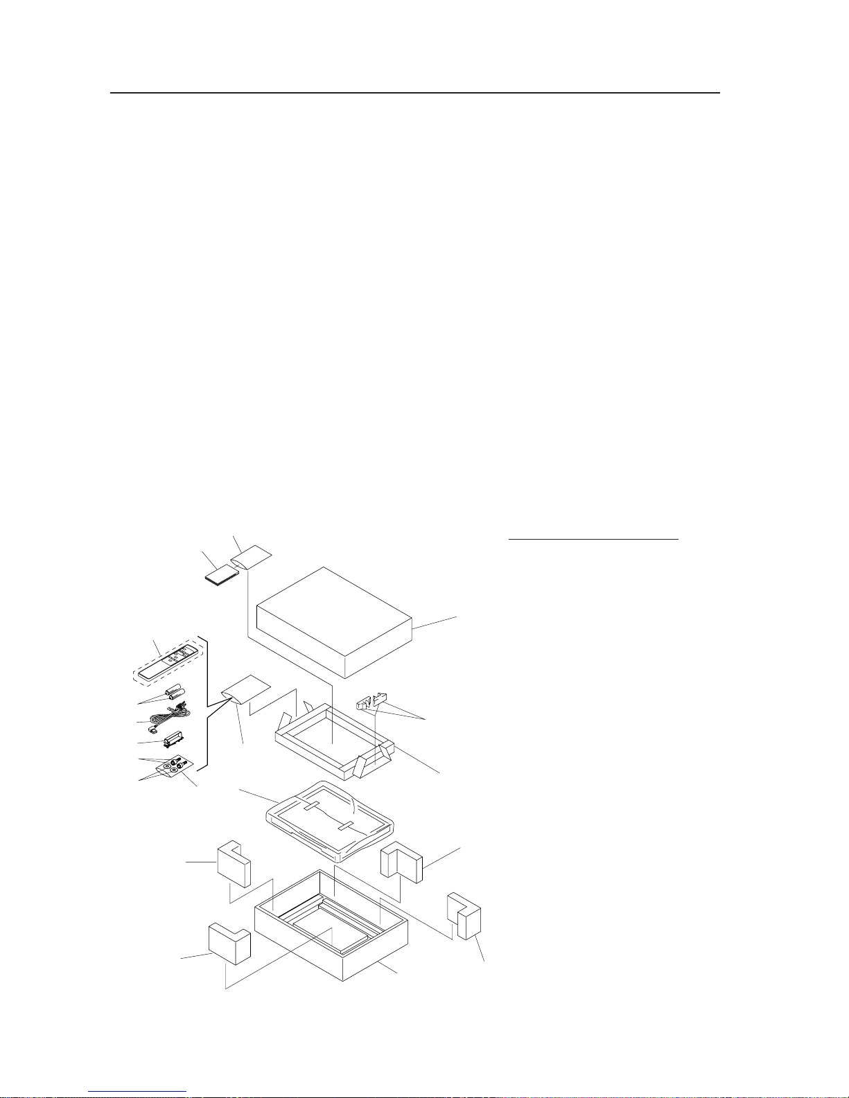
3.3.2 Unpacking
1) Packing specifications: 1130 (W) × 295 (H) × 852 (D) 39.5 kg <40.4 kg>
< > shows the PDP-V401E.
Installation procedure
No. Name
1. Upper carton
2. Stand
3. Upper pad
4. Mirror mat
5. Protector A
6. Under carton
7. Catalogue bag
8. Operating Instructions
9. Wrapping bag
10. Remote control (CU-V153)
11. Power cord (PDP-V401 only)
12. Cable clamp
13. 2P AA manganese dry cell, R6P
14. Plastic bag
15. Hexagonal-socket head bolt
16. Flat washer
1
2
5
5
6
5
5
4
3
16
14
15
12
11
13
10
9
7
8

17
<Ver. 2.1>
Installation procedure
2) Procedure for unpacking
1 Remove the PP band.
2 Slowly lift and remove the upper carton.
3 Remove the instruction manual (7 and 8), accessories (9), and stand (2), affixed to the upper pad with tape.
Caution: If the upper pad (3) is removed before first removing these items, the items may fall and damage the
product.
4 Remove the upper pad (3).
5 Remove the corner pad (5).
6 Remove the mirror mat (4).
7 Remove the product. (Requires two workers to remove the set.)
3) Movement after unpacking
Moving the product after unpacking requires two workers.
• Never drag the product on the floor.
• The display screen (front protective panel) is fragile. Move it slowly, and take care to avoid striking it or scraping
objects against it.
• Remove the protective film applied to the front protective panel only after construction and work are finished
and dust has settled.
18
<Ver. 2.1>
Installation procedure
3.3.3 Wiring
1) Power source connection
• Refer to Power cord connection on page 24 <36, 82> of the instruction manual.
• For power source capacity, see the description given in “3.1 Installation environment, 11) Power requirements”
in this manual.
2) Signal cable connection
(1) Connecting to a PC
• See the description given in Connecting to a PC , on pp. 19 to 20 <26 to 29, 72 to 75> of the instruction
manual.
(2) Connecting to a video cassette recorder
• See the description given in Connection to a video cassette recorder , on pp. 21 to 23 <30 to 35, 76 to
81> of the instruction manual.
(3) Precautions
• Use coaxial cables. For video signals, use the 3C-2V for lengths of 15 m or less, and the 5C-2V for lengths of
30 m or less. Since data signals are more easily degraded than video signals, use a thick cable (e.g. a 5C-2V
cable) for data communications, even for lengths of 15 m or less. Try to minimize the distance between the
signal transmission device and the plasma display unit.
• If a video cable is wired close to a dimmer, neon tube, air conditioner, or other device, or if it is wired in
parallel to a cable television cable, display performance may be affected.
< > shows the PDP-V401E.
3) Treatment of wires
• For long-term or permanent installations, rather than short-term installations for specific events, use wires of
the proper length, carefully considering the placement of all other wires.
• Place wires so that no load or force is applied to the connecting terminals. For short-term use, wires may be
bundled with string. For long-term installations, form wire bunches using cable clamps.
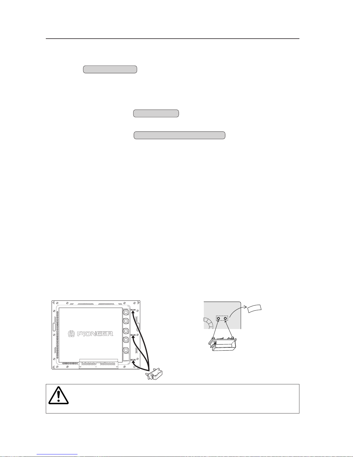
4) Mounting cable clamp
Use a cable clamp to form cable bunches in the upward direction, as shown in the drawing.
Cable clamps are supplied for bundling connection cables.
Follow these steps when using cable clamps:
Caution
Peel off the label covering the mounting holes before attaching the cable clamps.
When cables are inserted in a cable clamp, keep the clamp at least 10 cm from the wall to allow
ventilation.
<Back>
Peel off the paper at the back and insert the supplied
cable clamp into the mounting holes until it clicks.

19
<Ver. 2.1>
Installation procedure
20
<Ver. 2.1>
Special installations (Fixing on a structure)
3.4 Special installations
This display may be installed in several different positions, including wall-hanging and wall-embedding. Conditions,
including temperature, may restrict the use of certain positions or installation methods.
Consider installation methods and conditions, and see the description given in “3.1 to 3.3” in this chapter.
All the measurement conditions in this manual are set in conformity with the following:
• 100% white light is applied.
• After sufficient aging
All measurements should be performed under the same conditions. The aging time needed for measurement
depends on the size of the installation space, but the standard time is approximately 2.5 hours.
“Sufficient strength to withstand” means sufficient strength to withstand a weight four times that of the main body
including the metal fixture.
3.4.1 Fixing on a structure
To fix the machine on a structure, observe the following conditions:
1 Before fixing on a structure, make sure that the space around the structure is open.
2 After fixing on a structure, the distortion of the unit must be within 1 mm.
3 Do not block holes other than those shown blocked in the fixing figure on the next page.
4 Use a structure 20 mm or less in thickness.
(In the case of the fixing examples 1 and 4 on the next page, the thickness of the structure is not limited.)
5 If an L-shaped structure is used, the thickness of the structure must be 100 mm or less.
6 Use a structure with sufficient strength.
7 Care must be taken not to apply stress to the power cable.
* The descriptions in 2 - 7 indicate the common precautions for fixing the machine on the structure in “wall-hanging”
and “wall-embedding.”
✩ Operating temperature requirements
• Ambient temperature requirement: 0 to 40°C (Examples 1 and 2)
• Ambient temperature requirement: 0 to 35°C (Examples 3 and 4)
20 mm or less
in thickness
36 mm or less in width
The thickness of the examples 1 and
4 on the next page is not limited.
The thickness of the examples 1 and
4 on the next page is not limited.
20 mm or less
in thickness
36 mm or less in width
Distortion of the unit is 1mm max.
1mm MAX.
100 mm
or less
L-shaped structure
21
<Ver. 2.1>
Special installations (Fixing on a structure)
Example 1:
Beams
Beams
Ambient temperature requirement: 0 to 40°C
Example 2:
Ambient temperature requirement: 0 to 40°C
Ambient temperature requirement: 0 to 35°C
Ambient temperature requirement: 0 to 35°C
Example 3: Example 4:
Mount the display with the fans on the upper side.
22
<Ver. 2.1>
Special installations (Wall hanging)
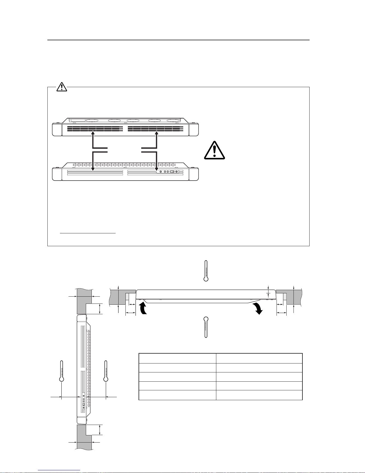
3.4.2 Wall hanging
This display may be wall-mounted. Since this form of mounting affects ventilation patterns inside, observe the following
requirements:
1 When mounting plate metal, avoid blocking any ventilation holes. Use plate metal of the size indicated in the
following drawing.
2 Provide space for adequate ventilation between the wall and the display.
3 Use plate metal having sufficient strength (with a safety factor of approximately four), and attach at four points (4-
point mounting) as shown below. Since wall installations involve certain hazards, always follow double-safety
procedures.
4 The following table lists proper operating temperatures. Use the display within the listed range of outside air
temperature.
5 Keep deformation of the display to 1 mm, including twisting and bending.
Clearance A to the wall
100 mm or more
50 mm or more
Less than 100 mm
0 to less than 50 mm
Operating temperatures
0 to 40 °C
0 to 40 °C (Animation)
0 to 35 °C (Still)
0 to 30 °C
Remarks
When this display is used with its back surface close to the
wall, interior temperatures will rise. The inner sensor is
activated at approximately 30 °C. Luminance decreases by 30%
and fan speed increases.
Do not block this area at either the top or bottom.
40mm
Do not block this area at either the left or right.
40mm
A
75mm 75mm
Wall
694 mm (center indicated)
75mm 75mm
23
<Ver. 2.1>
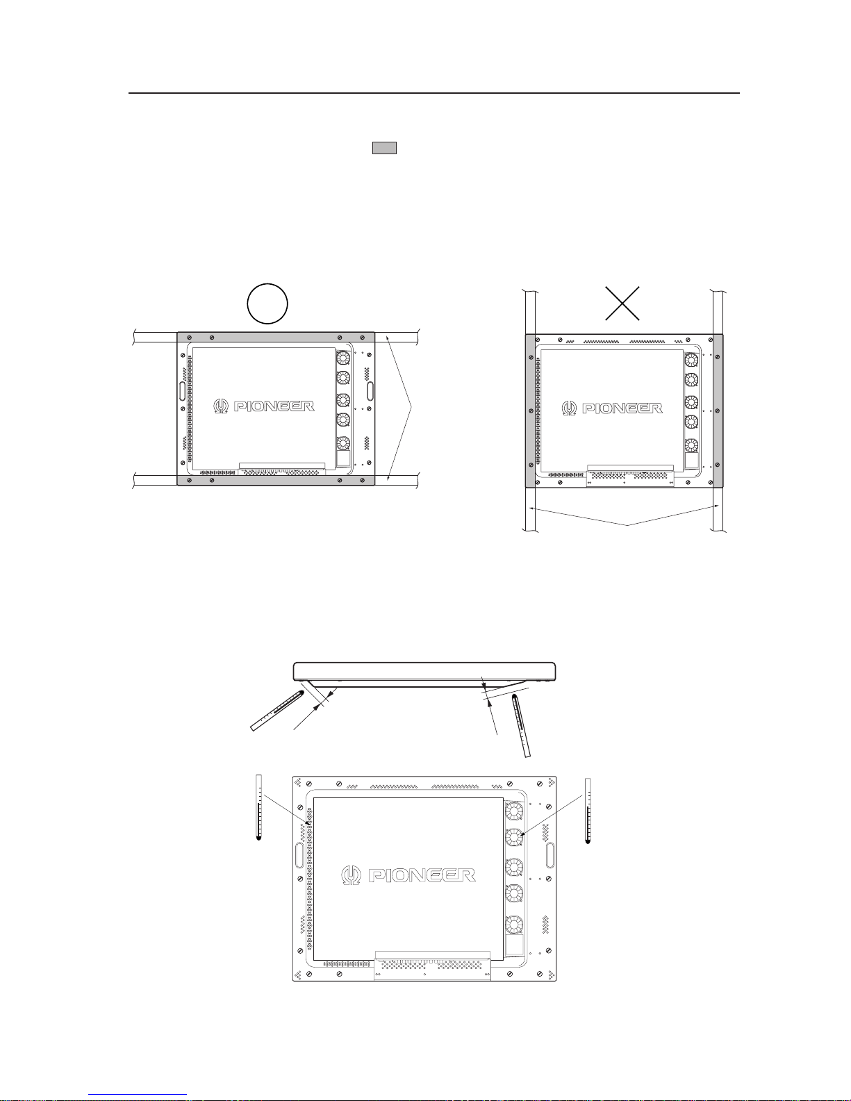
Special installations (Wall hanging)
Securing method: Basically, the unit is secured as indicated below. Keep open all areas other than the shaded parts.
The fixing method marked
cannot be used for the unit.
When the unit is fixed on a structure, select a structure of the proper thickness and height. Care
must also be taken regarding the number of fixing bolts to be used (see “3.4.1 Fixing on a structure”).
<Reference> After installation, measure the temperatures in the area shown in the figure below to make sure
that the values are within the specified range.
Bad example of blocking exhaust
<Incorrect><Correct>
Beams
Exhaust side
(temperature of the
exhaust from FAN)
Room temperate
+ 15 °C or less
Intake side
Room temperature
+ 5 °C or less
Beams
10 mm
10 mm
24
<Ver. 2.1>
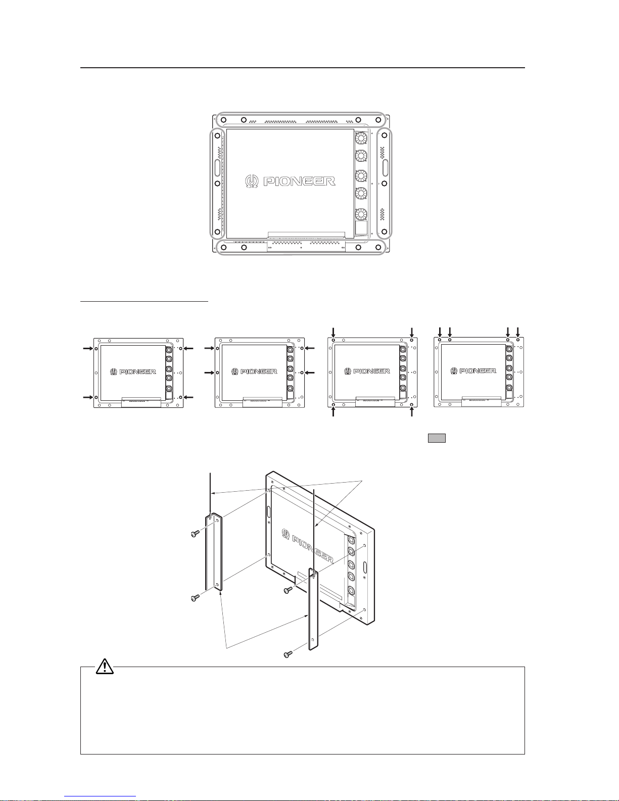
3.4.3 Wall embedding
This display is designed to accommodate embedding in a wall. Note that the allowable range of outside-air temperature
depends on the installation conditions. Please observe the following requirements:
1 If the unit must be embedded in the wall, you must not block the side slots of the unit.
Avoid blocking the ventilating holes in the rear as much as possible.
2 Use a metal mounting fixture that does not block the side slits or the back ventilation holes, and attach at a
minimum of four points. To avoid breaking the PDP panel, limit any twisting or bending stress applied to the
display to 1 mm or less.
3 Do not use cable clamps for this installation method. Cable clamps can interfere with proper ventilation and
result in device failure.
4 Installation conditions and ambient operating temperatures:
(1) If the back of the display will be unobstructed:
Never block the side slots. Avoid
blocking the ventilating holes of the
unit as much as possible.
Side slits
Special installations (Wall embedding)
A ≥ 100 mm, B ≤ 150 mm
A ≥ 100 mm, B ≥ 150 mm
A ≤ 100 mm, B ≤ 80 mm
A ≤ 100 mm, B ≥ 80 mm
X, Y space upper temperature limits
40 °C
40 °C (Animation), 35 °C (Still)
40 °C
35 °C
C
B
A
B
A
B
C
B
X
Y
Intake
MAX 20 mm
Exhaust
Take C to be 30 mm or more.
A
A
100 mm100 mm
Caution
25
<Ver. 2.1>
(2) When there is open space behind the wall and the angle (shape) as shown in the figure can be maintained on
the wall back:
If the back of the wall is tilted at 30 °C or less, the X, Y space temperature
may be set to a limit of 40 °C, regardless of wall thickness.
Special installations (Wall embedding)
MAX 20 mm
X
Y
30°
30°
30°
30°
Exhaust
Beams
Beams
Securing method: Basically, the unit is secured as indicated below. Keep open all areas other than the shaded parts.
The fixing method marked
cannot be used for the unit.
When the unit is fixed on a structure, select a structure of the proper thickness and height. Care
must also be taken regarding the number of fixing bolts to be used (see “3.4.1 Fixing on a structure”).
Bad example of blocking exhaust
<Incorrect><Correct>
26
<Ver. 2.1>
Special installations (Wall embedding)
A
\\
X
Y
A
B
A
C
Exhaust
B
(3) When the back of the wall is in a closed space:
Operating this display in confined spaces is not recommended.
• If the display is to be used in confined spaces, observe the following conditions shown in the drawing above:
A ≥ 150 mm
B ≥ 250 mm
C ≥ 30 mm
• Keep the temperature in the closed space “Y” and the open space “X” at 40 °C or less. In particular,
the space “Y” should be ventilated sufficiently by the air conditioner or fan so that hot air is not
trapped in the space.
Thus, everywhere in “Y” must be kept at 40°C or less. If hot air remains in the
closed space, the temperature may rise, causing a malfunction or fire. As a precaution in case of accidents,
the inner wall should have sufficient heat resistance or fire resistance. Direct air from the air conditioner in the
direction of the arrow (from where no fan is installed to where a fan is provided).
70 mm or less (on both left and right) MAX. 20 mm (on both left and right)
Flow of air from the
air conditioner
Exhaust fan (air flow rate:
2 m3/min or more)
Intake port
A
C
100 mm100 mm
27
<Ver. 2.1>
Special installations (Wall embedding)
<Reference> After installation, measure the temperatures in the area shown in the figure below to make sure
that the values are within the specified range.
Beams
Exhaust side
(temperature of the
exhaust from FAN)
Room temperate
+ 15 °C or less
Intake side
Room temperature
+ 5 °C or less
Beams
10 mm
10 mm
Securing method: Basically, the unit is secured as indicated below. Keep open all areas other than the shaded parts.
The fixing method marked
cannot be used for the unit.
When the unit is fixed on a structure, select a structure of the proper thickness and height. Care
must also be taken regarding the number of fixing bolts to be used (see “3.4.1 Fixing on a structure”).
Bad example of blocking exhaust
<Incorrect><Correct>
28
<Ver. 2.1>
Special installation (Ceiling suspension (using wires))
3.4.4 Ceiling suspension (using wires)
When suspending the display by wires, use a combination of two mounting rows, as shown in the diagram above (rows
A - B or C - D, from rows A - D). This is done to safeguard against subjecting the display to twisting forces. Use a
minimum of four mounting points.
Use the following metal fixture to keep load from centering on the two mounting points at the top. As discussed in
3.4.1 Fixing on a struc, avoid blocking any ventilation holes other than those in the shaded (
).
When attaching cables to the ceiling, install two cables at two independent points for safety.
‡‡
‡
×
Good example Bad example
AB
C
D
Wire
Metal fixture
If the display is
suspended close to a
wall, provide at least
300 mm clearance
between that wall
and the display.
Use mounting screws with minimum strength equal to that of mild steel cable, or stronger screws with hexagonal
socket heads.
The cable must be capable of supporting a load four times as heavy as the total weight of the display (30.8 kg
<31.6 kg>) plus the weight of the metal fixture, if one is used.
Provide auxiliary back-up cables to safeguard against breakage of main cables due to earthquakes etc..
< > shows the PDP-V401E.
29
<Ver. 2.1>
Special installation (Ceiling suspension (using wires))
Should the distance between the wall face and the unit be 300 mm or less, treat the clearance in the rear cover of the
pop or that of the fixture nearer to the wall as the clearance A and apply the wall hanging conditions in 3.4.2.
wall hanging.
A or more
Wall
Metal fixture Metal fixture
A
PDP
30
<Ver. 2.1>
Special installation (Installation with the screen downward)
3.4.5 Installation with the screen downward
This display is designed to be installed with the screen downward, but certain uses can interfere with proper ventilation.
Please observe the following conditions:
1 Use plate metal that keeps all single holes clear and has dimensions no larger than those given in the following
table.
2 Leave adequate ventilation space between the display and the ceiling.
3 Use plate metal having sufficient strength (incorporating a safety factor of approximately four), and secure at the
four points indicated in the following drawing (four-point mounting). Mounting plate metal on a ceiling involves
certain hazards. Make sure you provide adequate back-up safety measures.
4 Recommended ambient operating temperatures are given in the following table. Operate the display within this
range of temperatures.
5 The ceiling should closely approximate a perfectly flat plane. Keep deformation pressures applied to the display,
such as twisting and bending, at or below 1 mm.
Clearance A to the ceiling
100 mm or more
50 mm or more
Less than 100 mm
Less than 50 mm
Ambient operating temperatures
0 to 35 °C (Animation)
0 to 30 °C (Still)
0 to 30 °C
Cannot be used.
Ceiling
Do not block this area on either the top or the bottom.
Do not block this area on either the top or the bottom.
75mm
40mm
40mm
A
75mm
694 mm (center indicated)
75mm 75mm
Ceiling
 Loading...