


This file was downloaded and provided FREE OF CHARGE from the ManualDirectory community.
You can find many free to download Service Manuals & Schematics at
http://www.manualdirectory.co.uk

Service
Manual
FORD
GM-2077ZF/X1R/UC
ORDER NO.
CRT2823
AMPLIFIER |
|
|
|
|
|
|
GM-2077ZF |
X1R/UC |
|||||
GM-217 7ZF |
X1R/UC |
|
||||
|
|
|
|
|
|
|
|
VEHICLE |
PRODUCED AFTER |
FORD PART No. |
|
ID No. |
PIONEER MODEL No. |
|
FORD RANGER |
2002 |
2L54-18C808-AA |
− |
GM-2077ZF/X1R/UC |
|
|
FORD SPRT TRUCK |
2002 |
2L54-18C808-BA |
− |
GM-2177ZF/X1R/UC |
|
CONTENTS
1. |
SAFETY INFORMATION............................................ |
2 |
6. |
ADJUSTMENT ......................................................... |
19 |
2. |
EXPLODED VIEWS AND PARTS LIST ...................... |
3 |
7. |
GENERAL INFORMATION....................................... |
20 |
3. |
SCHEMATIC DIAGRAM............................................. |
6 |
|
7.1 DIAGNOSIS ....................................................... |
20 |
4. |
PCB CONNECTION DIAGRAM................................ |
12 |
|
7.1.1 DISASSEMBLY ............................................. |
20 |
5. |
ELECTRICAL PARTS LIST........................................ |
16 |
|
7.1.2 CONNECTOR FUNCTION DESCRIPTION ... |
21 |
|
|
|
8. |
SPECIFICATIONS ..................................................... |
21 |
For details, refer to "Important symbols for good services" .
PIONEER CORPORATION |
4-1, Meguro |
1-Chome, Meguro-ku, Tokyo 153-8654, Japan |
PIONEER ELECTRONICS (USA) INC. |
P.O.Box 1760, Long Beach, CA 90801-1760 U.S.A. |
|
PIONEER EUROPE NV Haven 1087 |
Keetberglaan 1, |
9120 Melsele, Belgium |
PIONEER ELECTRONICS ASIACENTRE PTE.LTD. 253 Alexandra Road, #04-01, Singapore 159936
C PIONEER CORPORATION 2001 |
K-ZZU. DEC. 2001 Printed in Japan |
|

GM-2077ZF,2177ZF
[ Important symbols for good services ]
In this manual, the symbols shown-below indicate that adjustments, settings or cleaning should be made securely. When you find the procedures bearing any of the symbols, be sure to fulfill them:
1. Product safety
You should conform to the regulations governing the product (safety, radio and noise, and other regulations), and should keep the safety during servicing by following the safety instructions described in this manual.
2. Adjustments
 To keep the original performances of the product, optimum adjustments or specification confirmation is indispensable. In accordance with the procedures or instructions described in this manual, adjustments should be performed.
3. Cleaning
For optical pickups, tape-deck heads, lenses and mirrors used in projection monitors, and other parts requiring cleaning, proper cleaning should be performed to restore their performances.
4. Shipping mode and shipping screws
To protect the product from damages or failures that may be caused during transit, the shipping mode should be set or the shipping screws should be installed before shipping out in accordance with this manual, if necessary.
5. Lubricants, glues, and replacement parts
Appropriately applying grease or glue can maintain the product performances. But improper lubrication or applying
 glue may lead to failures or troubles in the product. By following the instructions in this manual, be sure to apply the
 prescribed grease or glue to proper portions by the appropriate amount.For replacement parts or tools, the prescribed ones should be used.
CAUTION
This service manual is intended for qualified service technicians; it is not meant for the casual do-it-yourselfer. Qualified technicians have the necessary test equipment and tools, and have been trained to properly and safely repair complex products such as those covered by this manual.
Improperly performed repairs can adversely affect the safety and reliability of the product and may void the warranty. If you are not qualified to perform the repair of this product properly and safely, you should not risk trying to do so and refer the repair to a qualified service technician.
WARNING
This product contains lead in solder and certain electrical parts contain chemicals which are known to the state of California to cause cancer, birth defects or other reproductive harm.
Health & Safety Code Section 25249.6 - Proposition 65
2
GM-2077ZF,2177ZF
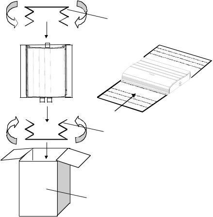
2. EXPLODED VIEWS AND PARTS LIST
2.1 PACKING
NOTE:
-Parts marked by “*” are generally unavailable because they are not in our Master Spare Parts List.
-Screws adjacent to mark on the product are used for disassembly.
-For the applying amount of lubricants or glue, follow the instructions in this manual. ( In the case of no amount instructions, apply as you think it appropriate.)
2
3
2
1
- PARTS LIST
Mark No. |
Description |
Part No. |
1 |
Contain Box |
HHL0317 |
2 |
Protector |
HHP0133 |
3 |
Protector |
HHP0134 |
3

GM-2077ZF,2177ZF
2.2 EXTERIOR
4
GM-2077ZF,2177ZF
- EXTERIOR SECTION PARTS LIST
Mark No. Description |
Part No. |
|
Mark No. Description |
Part No. |
||
1 |
Screw |
BBZ30P050FUC |
19 |
Connector(CN301) |
HKM0002 |
|
2 |
Screw |
BBZ30P060FMC |
20 |
Connector(CN851) |
HKM0003 |
|
3 |
Screw |
BBZ30P080FMC |
21 |
Holder |
HNC0082 |
|
4 |
Screw |
BSZ30P050FZK |
22 |
Holder |
HNC0117 |
|
5 |
Screw(M3x12) |
CBA1323 |
23 |
Screw(GM-2177ZF) |
BSZ50P120FZK |
|
6 |
Fuse(20A) |
HEK0020 |
24 |
Holder(GM-2177ZF) |
HNC0122 |
|
7 |
Screw |
PRZ30P060FSN |
25 |
Holder(GM-2177ZF) |
HNC0124 |
|
8 |
Screw(M3x5) |
HBA0006 |
|
|
|
|
9 |
Screw(M3x8) |
HBA0011 |
|
|
|
|
10 |
Case |
HNB0134 |
|
|
|
|
11 |
Panel |
HNB0154 |
|
|
|
|
12 |
Panel |
HNB0155 |
|
|
|
|
13 |
Holder |
HNC0080 |
|
|
|
|
14 |
Heat Sink(GM-2077ZF) |
HNR0209 |
|
|
|
|
|
Heat Sink(GM-2177ZF) |
HNR0216 |
|
|
|
|
15 |
Spacer |
HNV0016 |
|
|
|
|
16 |
Amp Unit(GM-2077ZF) |
HWH0181 |
|
|
|
|
|
Amp Unit(GM-2177ZF) |
HWH0185 |
|
|
|
|
17 |
Terminal(CN604) |
CKF1059 |
|
|
|
|
18 |
Connector(CN801) |
HKM0001 |
|
|
|
|
5
1 |
|
2 |
|
3 |
|
4 |
|
|
|
GM-2077ZF,2177ZF
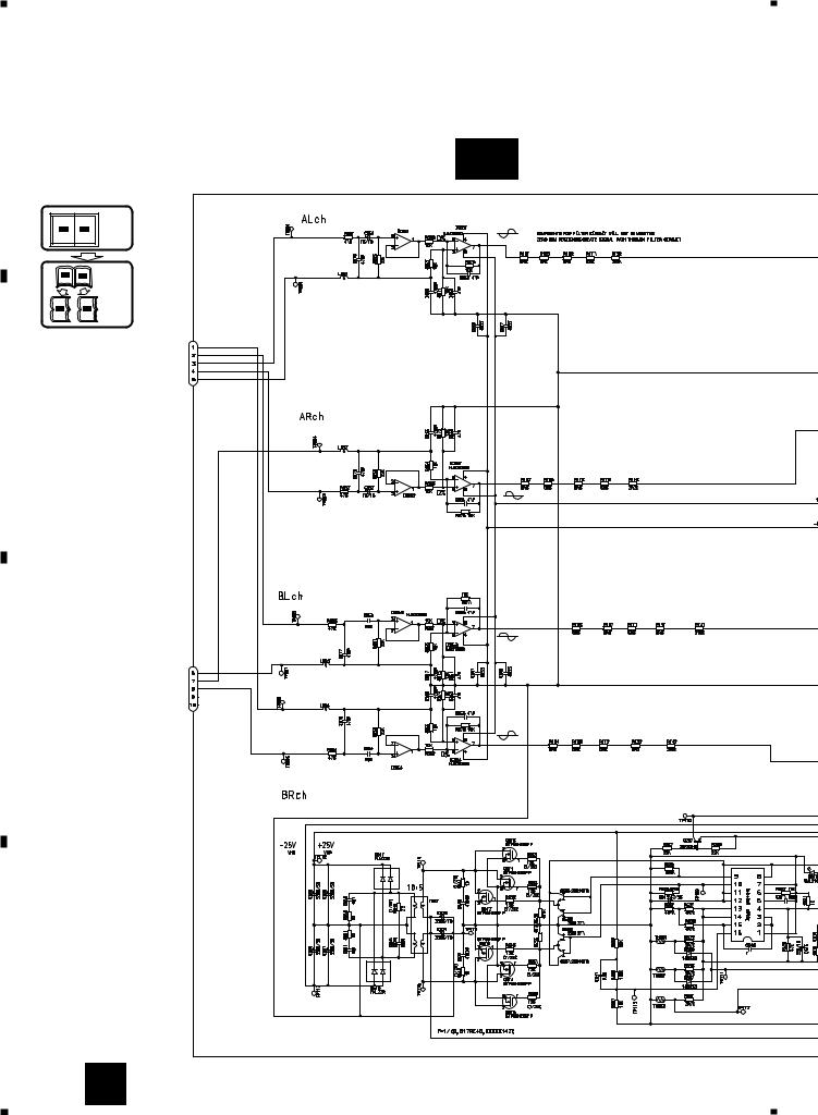
3. SCHEMATIC DIAGRAM
3.1 OVERALL CONNECTION DIAGRAM(GUIDE PAGE)
Note: When ordering service parts, be sure to refer to “EXPLODED VIEWS AND PARTS LIST” or “ELECTRICAL PARTS
A |
LIST”. |
A-a |
|
|
|||
|
|
|
|
|
|
Large size |
|
A-a |
A-b |
SCH diagram |
|
|
|
||
A-a |
A-b |
Guide page |
|
A-a |
A-b |
Detailed page |
|
|
|
|
ISOLATOR |
|
|
|
1-CN851 |
B |
|
|
|
|
|
|
ISOLATOR |
|
|
|
ISOLATOR |
C |
|
|
2-CN851 |
|
|
|
|
|
|
|
ISOLATOR |
|
|
|
REGULATOR |
D |
|
|
|
DC/CD CONVERTER
6 A
1 |
|
2 |
|
3 |
|
4 |
|
|
|
||||
|
|
|
 Loading...