

Page 1

INSTALLATION MANUAL
MANUEL D’INSTALLATION
NAVIGATION AV SYSTEM
SISTEMA DE NAVEGACIÓN AV
NAVIGATIONS-/AV-SYSTEM
SYSTEME DE NAVIGATION AV
SISTEMA DI NAVIGAZIONE AV
AV NAVIGATIESYSTEEM
AVIC-F20BT
AVIC-F920BT
English NederlandsItalianoFrançaisDeutschEspañol
Page 2

Contents
IMPORTANT INFORMATION
ABOUT YOUR NEW NAVIGATION SYSTEM
AND THIS MANUAL 3
IMPORTANT SAFEGUARDS
PLEASE READ ALL OF THESE
INSTRUCTIONS REGARDING YOUR
NAVIGATION SYSTEM AND RETAIN THEM
FOR FUTURE REFERENCE 4
Connecting the System
Precautions before connecting the
system 5
Before installing this product 5
To prevent damage 6
– Notice for the blue/white lead 6
Parts supplied 7
– AVIC-F20BT 7
– AVIC-F920BT 7
Connecting the system 8
Connecting the power cord (1) 10
Connecting the power cord (2) 12
When connecting to separately sold power
amp 14
When connecting a rear view camera 16
When connecting the external video
component 17
– Using “AV1 Input” (AV1) 17
– Using “AV2 Input” (AV2) 18
When connecting the rear display 18
– When using a rear display connected to
rear video output 18
When connecting the external unit featuring
video source 19
– For AVIC-F20BT users 21
Installing this navigation system 21
– Installation notes 21
– Parts supplied 22
– Before installing this navigation
unit 23
– Installation with the holder and side
bracket 23
– Installation using the screw holes on
the side of the navigation unit 24
Installing the GPS aerial 25
– Installation notes 25
– Parts supplied 25
– When installing the aerial inside the
vehicle (on the dashboard or rear
shelf) 26
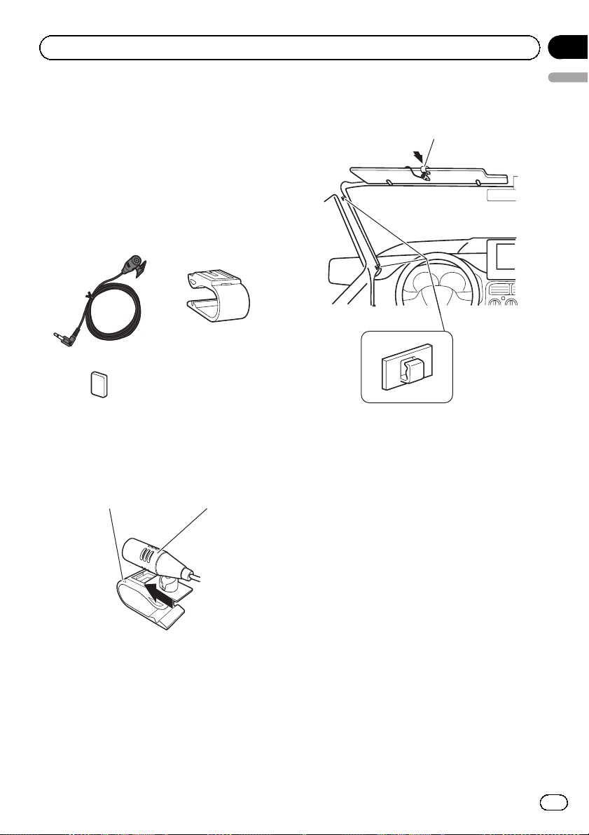
Installing the microphone 27
– Parts supplied 27
– Mounting on the sun visor 27
– Installation on the steering column 28
– Adjusting the microphone angle 28
Installation
Precautions before installation 20
To guard against electromagnetic
interference 20
Before installing 20
2
Engb
Page 3

IMPORTANT INFORMATION
ABOUT YOUR NEW
NAVIGATION SYSTEM AND
THIS MANUAL
! The navigation features of this product
(and rear view camera option if purchased)
are intended solely to aid you in the operation of your vehicle. It is not a substitute for
your attentiveness, judgement and care
when driving.
! Never use this navigation system to route
to hospitals, police stations, or similar facilities in an emergency. Please call the appropriate emergency number.
! Do not operate this navigation system (or
the rear view camera option if purchased) if
doing so will divert your attention in any
way from the safe operation of your vehicle.
Always observe safe driving rules and follow all existing traffic regulations. If you experience difficulty in operating the system
or reading the display, park your vehicle in
a safe location and apply the handbrake before making the necessary adjustments.
! This manual explains how to install this na-
vigation system in your vehicle. Operation
of this navigation system is explained in
the separate manuals for the navigation
system.
! Do not install this product where it may (i)
obstruct the driver’s vision, (ii) impair the
performance of any of the vehicle’s operating systems of safety features, including
airbags, hazard lamp buttons or (iii) impair
the driver’s ability to safely operate the vehicle. In some cases, it may not be possible
to install this product because of the vehicle type or the shape of the vehicle interior.
Section
01
English
Engb
3
Page 4

Section
02
IMPORTANT SAFEGUARDS
WARNING
Pioneer does not recommend that you install
your navigation system yourself. We recommend that only authorised Pioneer service
personnel, who have special training and experience in mobile electronics, set up and install this product. NEVER SERVICE THIS
PRODUCT YOURSELF. Installing or servicing this product and its connecting cables
may expose you to the risk of electric shock
or other hazards, and can cause damage to
the navigation system that is not covered by
warranty.
PLEASE READ ALL OF THESE
INSTRUCTIONS REGARDING
YOUR NAVIGATION SYSTEM
AND RETAIN THEM FOR
FUTURE REFERENCE
1 Read this manual fully and carefully before in-
stalling your navigation system.
2 Keep this manual handy for future reference.
3 Pay close attention to all warnings in this
manual and follow the instructions carefully.
4 This navigation system may in certain circum-
stances display erroneous information regard-
ing the position of your vehicle, the distance
of objects shown on the screen, and compass
directions. In addition, the system has certain
limitations, including the inability to identify
one-way streets, temporary traffic restrictions
and potentially unsafe driving areas. Please
exercise your own judgement in the light of
actual driving conditions.
5 As with any accessory in your vehicle’s inter-
ior, the navigation system should not divert
your attention from the safe operation of your
vehicle. If you experience difficulty in operat-
ing the system or reading the display, please
make adjustments while safely parked.
6 Please remember to wear your seat belt at all
times while operating your vehicle. If you are
ever in an accident, your injuries can be con-
siderably more severe if your seat belt is not
properly fastened.
7 Certain country and government laws may
prohibit or restrict the placement and use of
this system in your vehicle. Please comply
with all applicable laws and regulations regarding the use, installation and operation of
your navigation system.
4
Engb
Page 5
Connecting the System
Section
03
Precautions before
connecting the system
CAUTION
! If you decide to perform the installation
yourself, and have special training and experience in the mobile electronics installations, please carefully follow all of the
steps in the installation manual.
! Secure all wiring with cable clamps or
electrical tape. Do not allow any bare wiring to remain exposed.
! Do not directly connect the yellow lead of
this product to the vehicle battery. If the
lead is directly connected to the battery,
engine vibration may eventually cause
the insulation to fail at the point where
the wire passes from the passenger compartment into the engine compartment. If
the yellow lead’s insulation tears as a result of contact with metal parts, short-circuiting can occur, resulting in
considerable danger.
! It is extremely dangerous to allow the
cables to become wound around the steering column or gearstick. Be sure to install
this product, its cables, and wiring away
in such a way that they will not obstruct
or hinder driving.
! Make sure that the cables and wires are
routed and secured so they will not interfere with or become caught in any of the
vehicle’s moving parts, especially the
steering wheel, gearstick, handbrake, sliding seat tracks, doors, or any of the vehicle’s controls.
! Do not route wires where they will be ex-
posed to high temperatures. If the insulation heats up, wires may become
damaged, resulting in a short circuit or
malfunction and permanent damage to
the product.
! Do not cut the GPS aerial cable to shorten
it or use an extension to make it longer.
Altering the aerial cable could result in a
short circuit or malfunction.
! Do not shorten any leads. If you do, the
English
protection circuit (fuse holder, fuse resistor or filter, etc.) may fail to work properly.
! Never feed power to other electronic pro-
ducts by cutting the insulation of the
power supply lead of the navigation system and tapping into the lead. The current
capacity of the lead will be exceeded,
causing overheating.
Before installing this product
! Use this unit with a 12-volt battery and ne-
gative earthing only. Failure to do so may
result in a fire or malfunction.
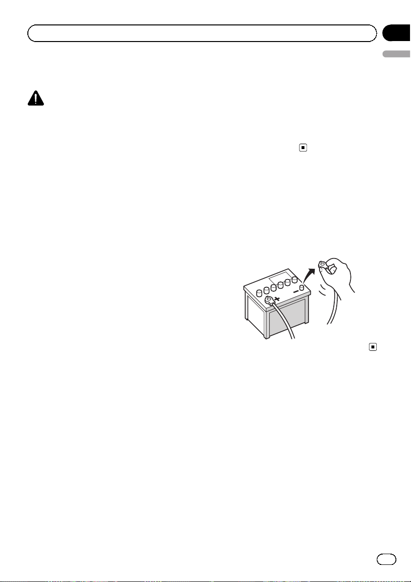
! To avoid shorts in the electrical system, be
sure to disconnect the (–) battery cable before beginning installation.
Engb
5
Page 6
Section
03
Connecting the System
To prevent damage
WARNING
! Use speakers over 50 W (output value)
and between 4 W to 8 W (impedance value).
Do not use 1 W to 3W speakers for this
unit.
! The black lead is earth. Please earth this
lead separately from the earth of high-cur-
rent products such as power amps. Do not
earth more than one product together
with the earth from another product. For
example, you must separately earth any
amp unit away from the earth of this navi-
gation system. Connecting earths to-
gether can cause a fire and/or damage the
products if their earths became detached.
! When replacing the fuse, be sure to only
use a fuse of the rating prescribed on this
product.
! When disconnecting a connector, pull the
connector itself. Do not pull the lead, as
you may pull it out of the connector.
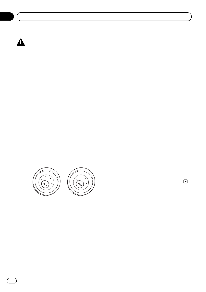
! This product cannot be installed in a vehi-
cle without ACC (accessory) position on
the ignition switch.
C
C
A
O
F
N
F
O
S
T
A
R
T
O
F
N
F
O
S
T
A
R
T
! Since a unique BPTL circuit is employed,
do not directly earth the * side of the
speaker lead or connect the * sides of the
speaker leads together. Be sure to connect
the * side of the speaker lead to the *
side of the speaker lead on this navigation
system.
! If the RCA pin jack on this product will not
be used, do not remove the caps attached
to the end of the connector.
Notice for the blue/white lead
! When the ignition switch is turned on (ACC
ON), a control signal is output through the
blue/white lead. Connect to an external
power amp’s system remote control terminal, the auto-aerial relay control terminal,
or the aerial booster power control terminal
(max. 300mA 12 V DC). The control signal
is output through the blue/white lead, even
if the audio source is switched off.
! Be sure not to use this lead as the power
supply lead for the external power amps.
Such connection could cause excessive
current drain and malfunction.
! Be sure not to use this lead as the power
supply lead for the auto-aerial or aerial
booster. Such connection could cause excessive current drain and malfunction.
ACC position No ACC position
! To avoid short-circuiting, cover the discon-
nected lead with insulating tape. It is espe-
cially important to insulate all unused
speaker leads, which if left uncovered may
cause a short circuit.
! Attach the connectors of the same colour
to the corresponding coloured port, i.e.,
blue connector to the blue port, black to
black, etc.
! Refer to the owner’s manual for details on
connecting the power amp and other units,
then make connections accordingly.
6
Engb
Page 7
Connecting the System
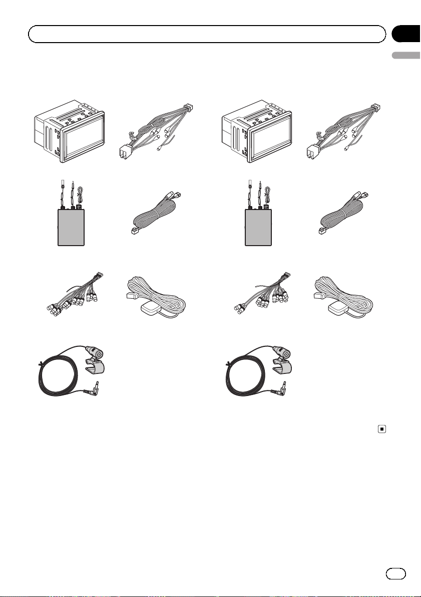
Parts supplied
AVIC-F20BT
Section
03
English
AVIC-F920BT
The navigation unit Power cord
RDS-TMC tuner USB and mini-jack
connector
RCA connector GPS aerial
Microphone
The navigation unit Power cord
RDS-TMC tuner USB and mini-jack
connector
RCA connector GPS aerial
Microphone
Engb
7
Page 8
Section
03
Connecting the System
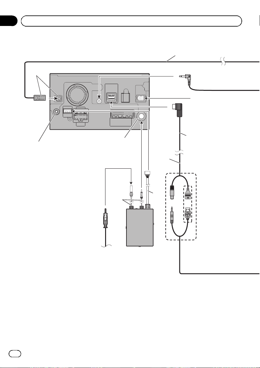
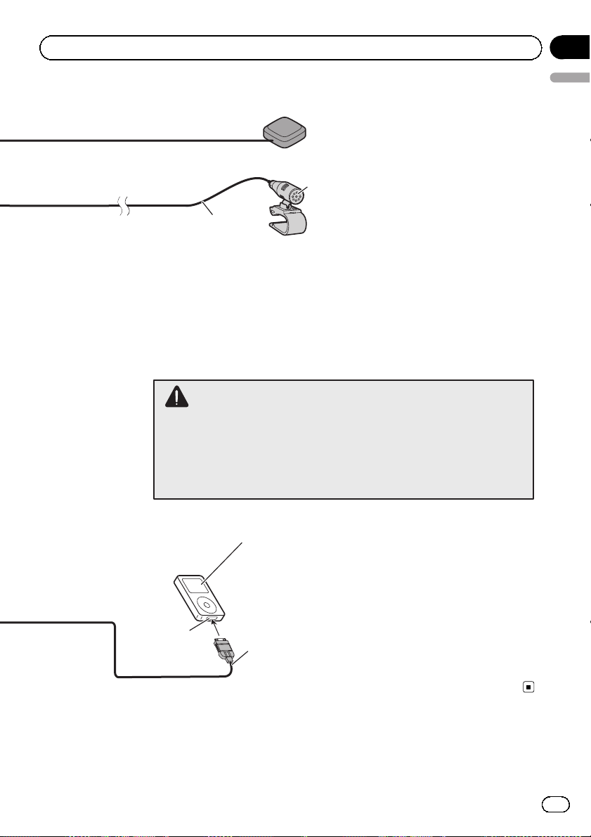
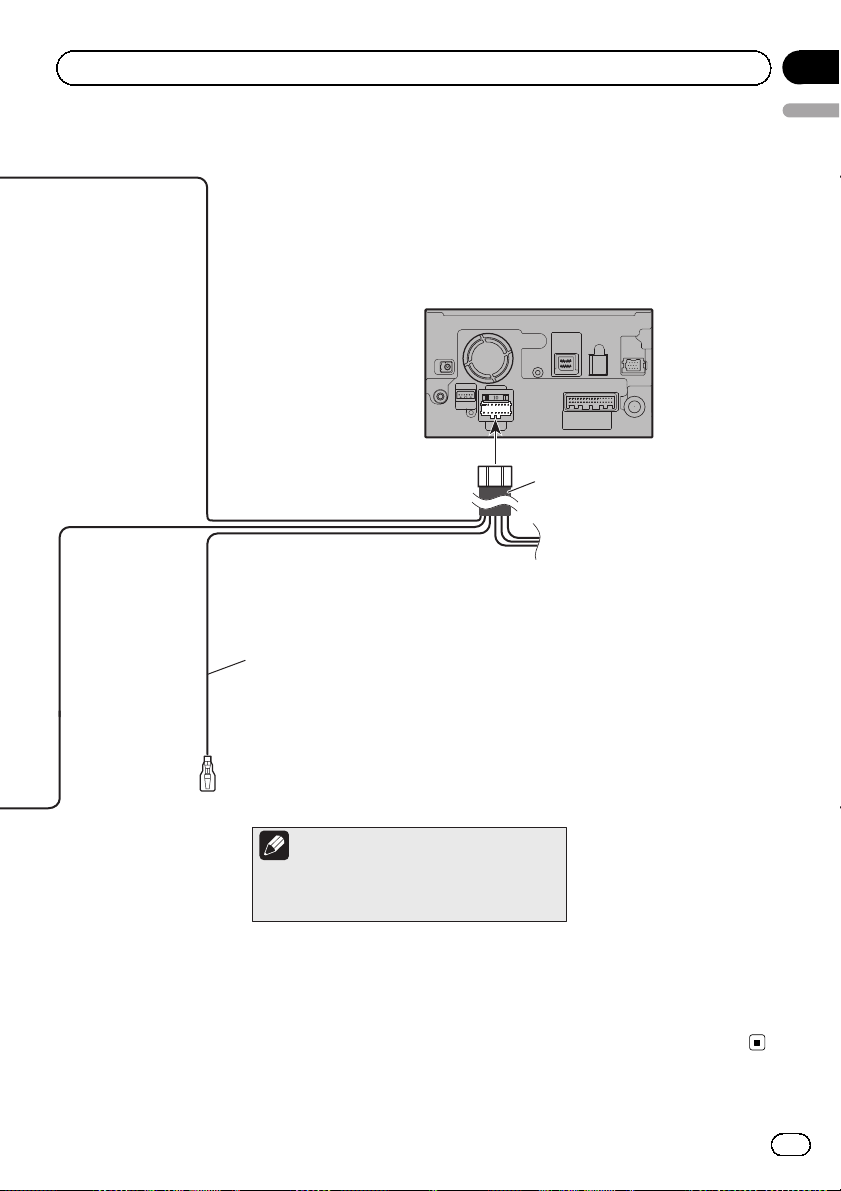
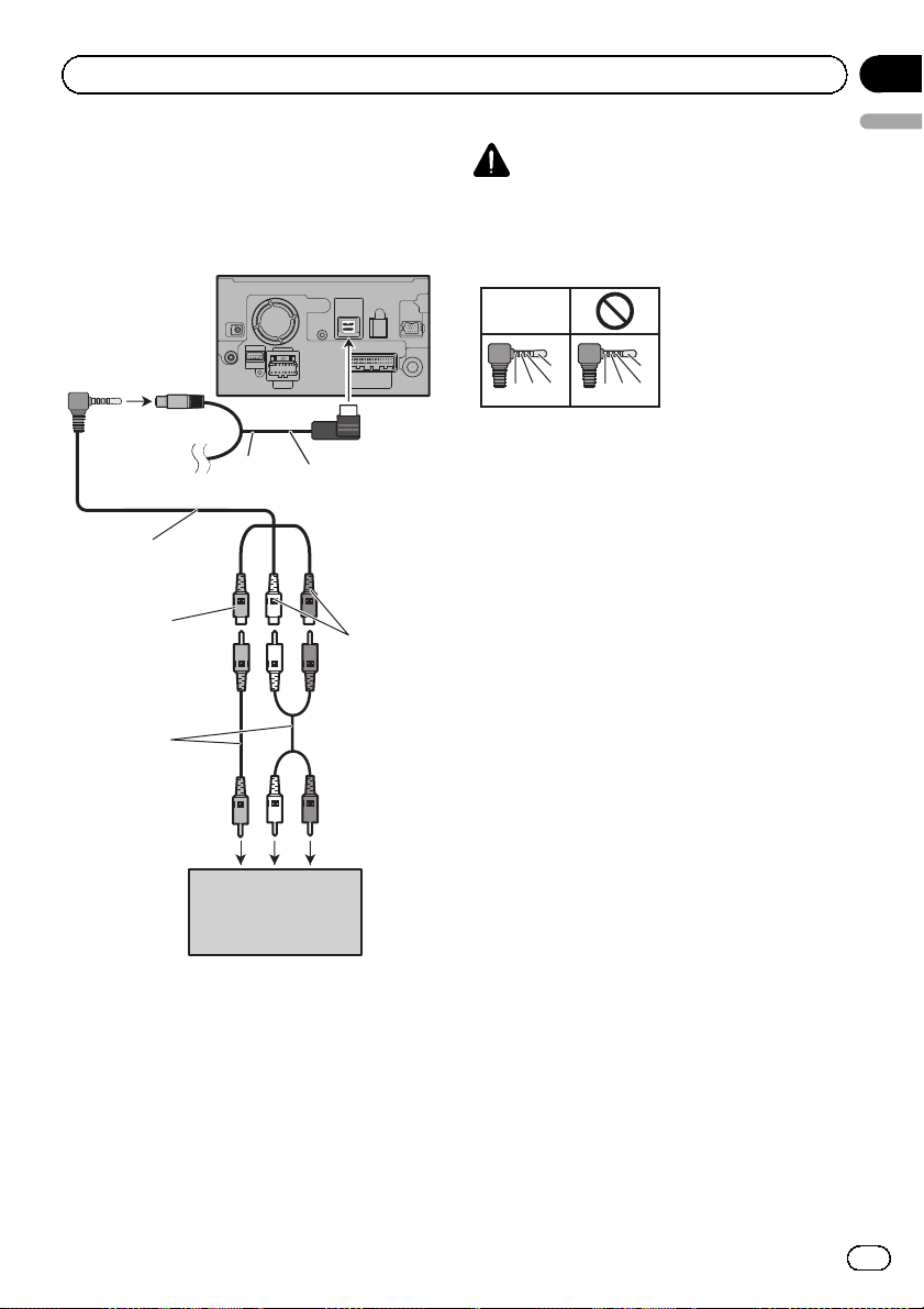
Connecting the system
3.55 m
Green
WIRED REMOTE INPUT
Please see the Instruction
Manual for the Wired Remote
Control Adapters (sold separately).
The navigation unit
Vehicle
aerial
Aerial
jack
30 cm
RDS-TMC tuner
1 m
IP-BUS connector
(IP-BUS connector is
available for AVIC-F20BT.)
USB and mini-jack
connector
2 m
(*1)
Connect either the
USB Interface Cable
for iPod or an
appropriate USB
storage device.
(*1)
(*2)
(*2)
— When connecting your iPod, both connections are necessary.
— It is necessary to set “AV1 Input” in “AV System Settings” to “iPod”
when connecting the iPod. (For details, refer to Operation Manual.)
8
Engb
Page 9
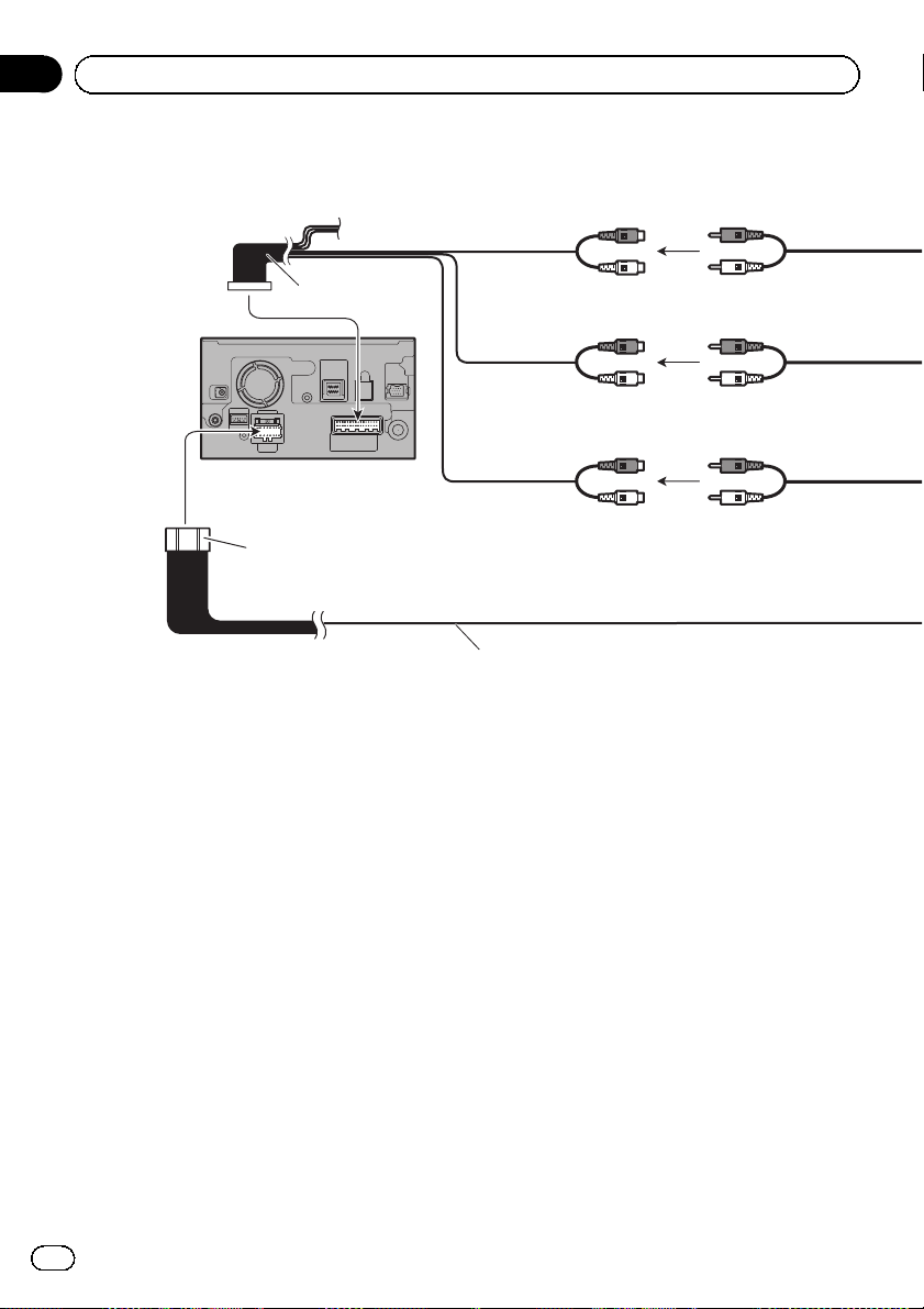
Connecting the System
4 m
WARNING
· To avoid the risk of accident and the potential violation of applicable laws, this
product should never be used while the vehicle is being driven except for
navigation purposes. And, also Rear Displays should not be in a location where it
is a visible distraction to the driver.
· In some countries, the viewing of images on a display inside a vehicle even by
persons other than the driver may be illegal. Where such regulations apply they
must be obeyed and this product’s video source should not be used.
Section
03
English
GPS aerial
Microphone
Dock
connector
port
iPod with
Dock Connector(*3)
(*3)
For details concerning
operations and compatibility ,
refer to Operation Manual.
USB Interface Cable for iPod
(CD-IU50V) (sold separately)
Engb
9
Page 10
Section
03
Connecting the System
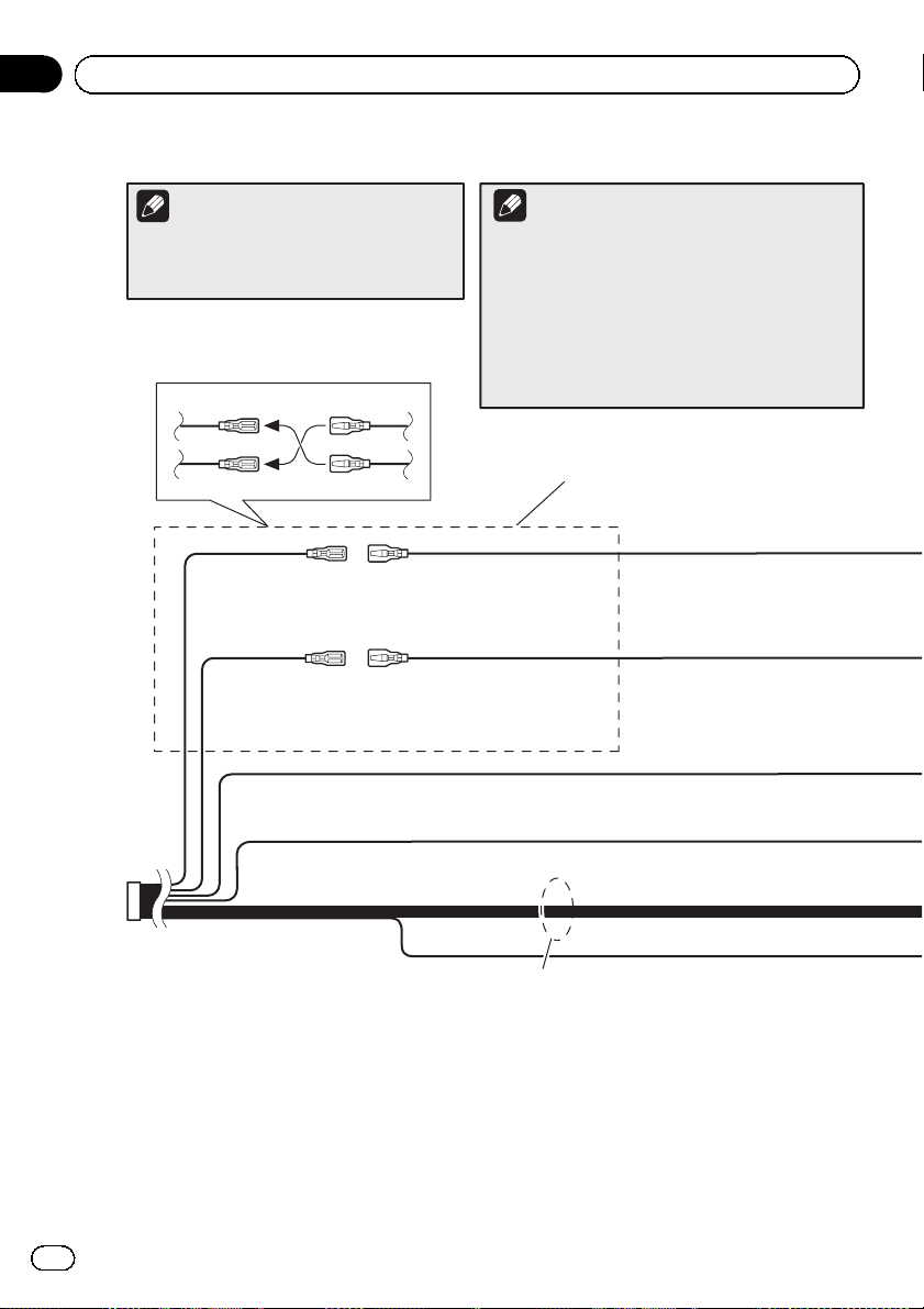
Connecting the power cord (1)
Note
Depending on the kind of vehicle, the function
of *2 and *4 may be different. In this case, be
sure to connect *1 to *4 and *3 to *2.
*2
*4
Yellow (*2)
Back-up
(or accessory)
Red (*4)
Accessory
(or back-up)
*1
*3
Yellow (*1)
To terminal always supplied
with power regardless of
ignition switch position.
Red (*3)
To electric terminal controlled by
ignition switch (12 V DC) ON/OFF.
Orange/white
To lighting switch terminal.
Notes
· When a subwoofer (*5) is connected to this
navigation system instead of a rear speaker, change
the rear output setting in the Initial Setting. (Refer to
Operation Manual.) The subwoofer output of this
navigation system is monaural.
· When using a subwoofer of 70 W (2 Ω), be sure to
connect with violet and violet/black leads of this
navigation system. Do not connect anything with
green and green/black leads.
Connect leads of the
same colour to each other.
10
Black (earth)
To vehicle (metal) body.
ISO connector
Speaker leads
White: Front left
White/black: Front left
Grey: Front right
Grey/black: Front right
Green: Rear left or Subwoofer (*5)
Green/black: Rear left or Subwoofer (*5)
Violet: Rear right or Subwoofer (*5)
Violet/black: Rear right or Subwoofer (*5)
Engb
Page 11
Connecting the System
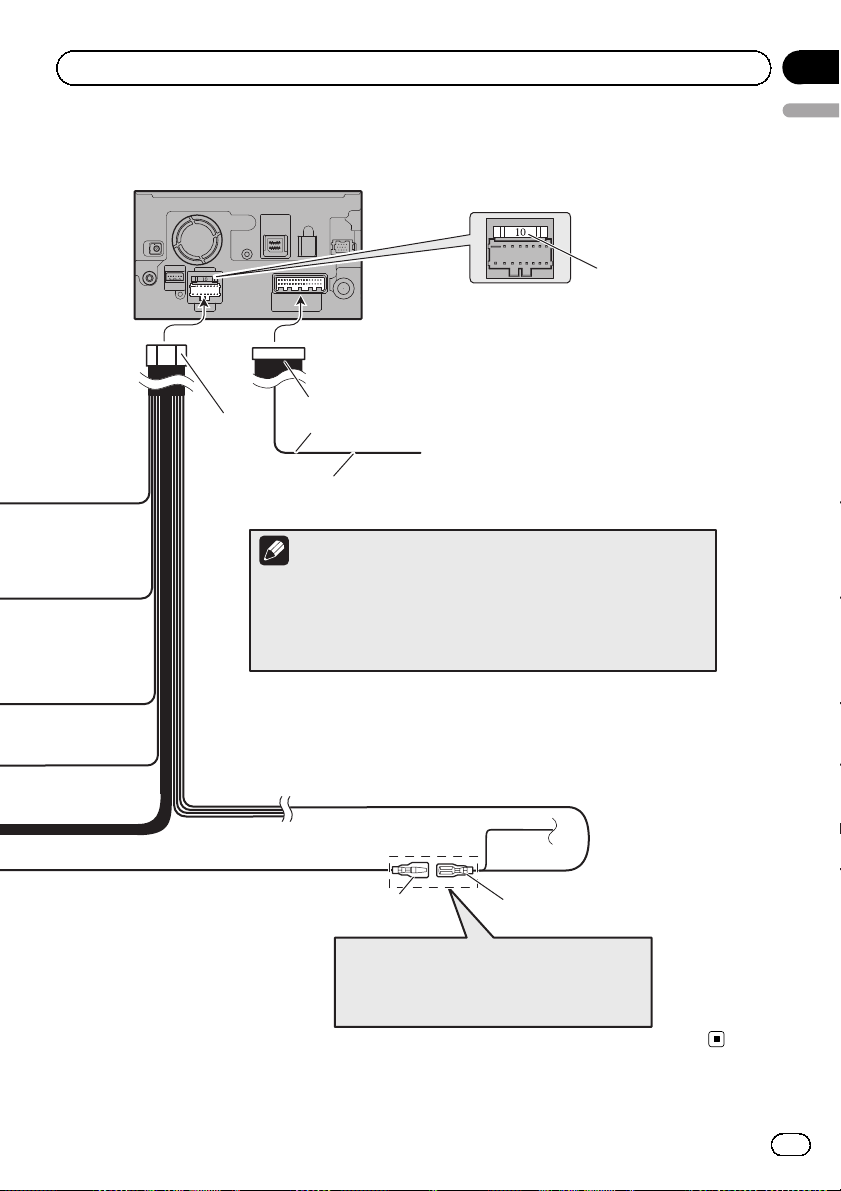
The navigation unit
RCA connector
Power cord
Yellow/black
If you use an equipment with mute function, connect that equipment to the
Audio Mute lead. If not, keep this lead free of any connections.
15 cm
Note
Audio source will be set to mute or attenuate, while the following sounds
will not be muted or attenuated. For details, see Operation Manual.
— voice guidance of the navigation
— incoming ringtone and incoming voice of the mobile phone that is
connected to this navigation system via Bluetooth wireless technology
Section
03
English
Fuse (10 A)
Blue/white (*6)
The pin position of the ISO connector will differ
depending on the type of vehicle. Connect *6 and
*7 when Pin 5 is an aerial control type. In other
types of vehicle, never connect *6 and *7.
Blue/white (*7)
To auto-aerial relay control
terminal (max. 300 mA 12 V DC).
Engb
11
Page 12
Section
03
Connecting the System
Connecting the power cord (2)
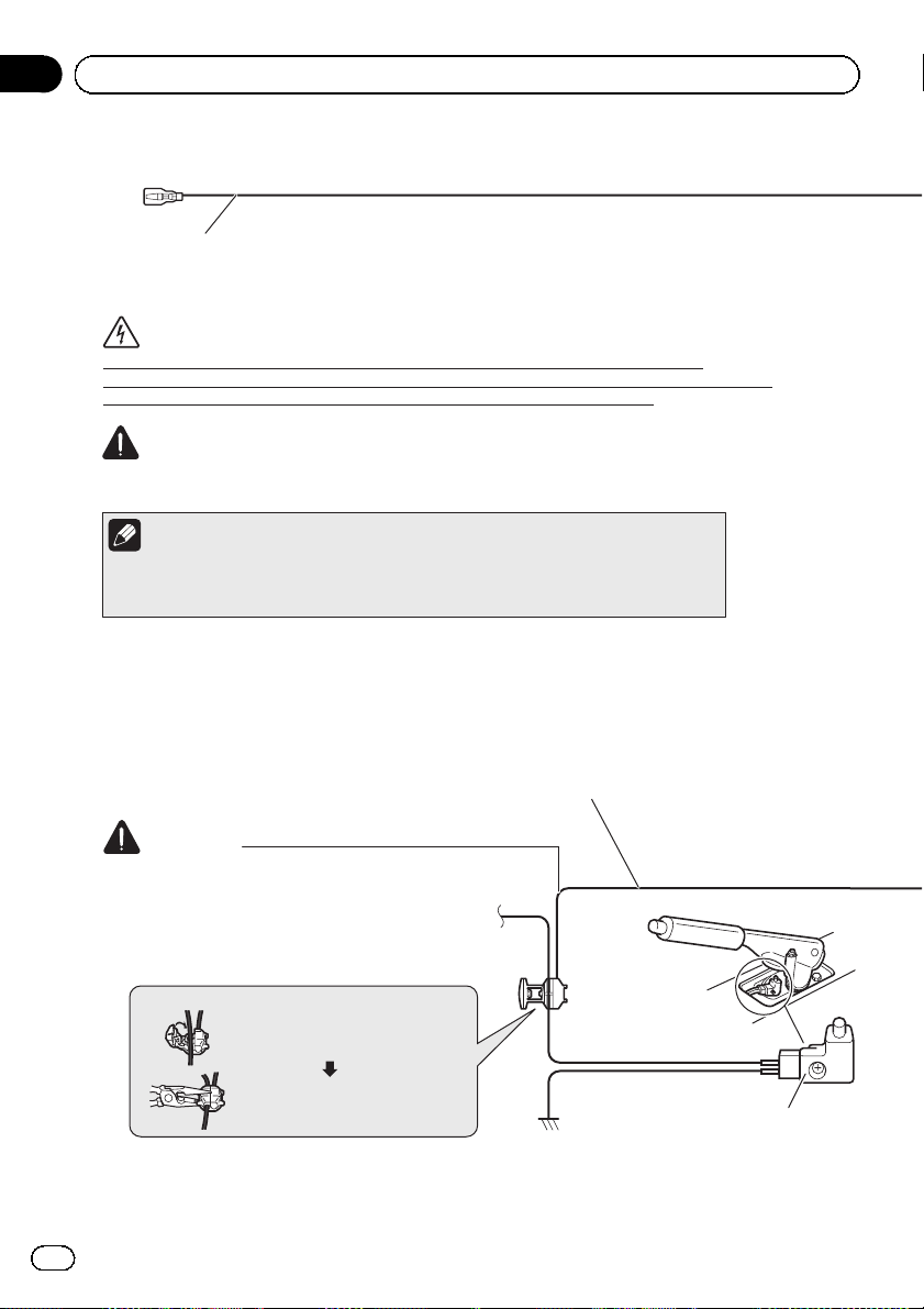
Pink (CAR SPEED SIGNAL INPUT)
The mobile navigation system is connected here to detect the distance the vehicle travels. Always
connect the vehicle’s speed detection circuit. Failure to make this connection will increase errors in
the location display.
WARNING
IMPROPER CONNECTION MAY RESULT IN SERIOUS DAMAGE OR INJURY INCLUDING
ELECTRICAL SHOCK, AND INTERFERENCE WITH THE OPERATION OF THE VEHICLE´S ANTILOCK
BRAKING SYSTEM, AUTOMATIC GEARBOX AND SPEEDOMETER INDICATION.
CAUTION
It is strongly suggested that the speed pulse wire be connected for accuracy of navigation
and better performance.
Note
The position of the speed detection circuit and the position of the handbrake switch vary
depending on the vehicle model. For details, consult your authorised Pioneer dealer or an
installation professional.
Light green (PARKING BRAKE)
Used to detect the ON/OFF status of the handbrake. This lead must be connected to the power supply side
of the handbrake switch.
If this connection is made incorrectly or omitted, certain functions of your navigation system will be
unusable.
WARNING
LIGHT GREEN LEAD AT POWER CONNECTOR IS
DESIGNED TO DETECT PARKED STATUS AND MUST
BE CONNECTED TO THE POWER SUPPLY SIDE OF THE
HANDBRAKE SWITCH. IMPROPER CONNECTION OR
USE OF THIS LEAD MAY VIOLATE APPLICABLE LAW
AND MAY RESULT IN SERIOUS INJURY OR DAMAGE.
Connection method
12
Engb
Clamp the handbrake switch
power supply side lead.
Clamp firmly with needle-nosed
pliers.
Power supply side
Earth side
Handbrake switch
Page 13
Connecting the System
Section
03
English
The navigation unit
Power cord
Violet/white (REVERSE GEAR SIGNAL INPUT)
This is connected so that the navigation system can detect
whether the vehicle is moving forwards or backwards.
Connect the violet/white lead to the lead whose voltage
changes when the reverse gear is engaged. Unless
connected, the sensor may not detect your vehicle
travelling forward/backward properly, and thus the position
of your vehicle detected by the sensor may be misaligned
from the actual position.
Note
When you use a rear view camera, please make
sure to connect this lead. Otherwise you cannot
switch to rear view camera picture.
Engb
13
Page 14
Section
03
Connecting the System
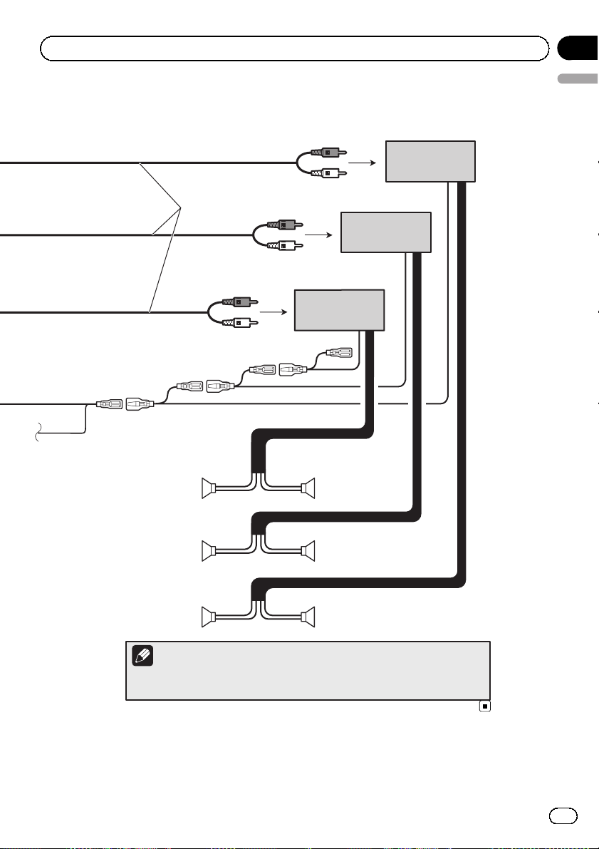
When connecting to separately sold power amp
Subwoofer output
(SUBWOOFER OUTPUT)
25 cm (*1)
RCA connector
The navigation unit
Power cord
31 cm (*2)
Rear output
(REAR OUTPUT)
30 cm (*1)
15 cm (*2)
Front output
(FRONT OUTPUT)
30 cm (*1)
15 cm (*2)
(*1)
AVIC-F20BT
Blue/white
To system control terminal of the power amp
(max. 300 mA 12 V DC).
(*2)
AVIC-F920BT
14
Engb
Page 15
Connecting the System
RCA cables
(sold separately)
System remote control
Section
03
English
Powe r amp
(sold separately)
Power amp
(sold separately)
Power amp
(sold separately)
Left Right
Front speaker
Rear speaker
Subwoofer
Front speaker
Rear speaker
Subwoofer
Note
You can change the RCA output of the subwoofer depending on your subwoofer
system. (Refer to Operation Manual.)
Engb
15
Page 16
Section
03
Connecting the System
When connecting a rear
view camera
When this product is used with a rear view
camera, it is possible to automatically switch
from the video to rear view image when the
gearstick is moved to REVERSE (R). Rear
View mode also allows you to check what is
behind you while driving.
WARNING
USE INPUT ONLY FOR REVERSE OR MIRROR
IMAGE REAR VIEW CAMERA. OTHER USE MAY
RESULT IN INJURY OR DAMAGE.
CAUTION
! The screen image may appear reversed.
! The rear view camera function is to use this
product as an aid to keep an eye on trailers, or
backing into a tight parking spot. Do not use
this function for entertainment purposes.
! The object in rear view may appear closer or
more distant than in reality.
! Please note that the edges of the rear view
camera images may differ slightly according
to whether full screen images are displayed
when backing, and whether the images are
used for checking the rear when the vehicle is
moving forward.
Rear view camera
(e.g. ND-BC4)
(sold separately)
(*1)
AVIC-F20BT
(*2)
AVIC-F920BT
Power cord
Violet/white
(REVERSE GEAR SIGNAL INPUT)
For more details about the wiring, refer to Connecting
the power cord (2) on page 12.
To video output
Brown
(REAR VIEW CAMERA IN)
RCA connector
The navigation unit
RCA cable
20 cm (*1)
23 cm (*2)
16
Notes
! It is necessar y to set “Camera” in “Back
Camera Settings” to “On” when connect-
ing the rear view camera. (For details, refer
to Operation Manual.)
! Connect to the rear view camera. Do not
connect to any other equipment.
Engb
Page 17
Connecting the System
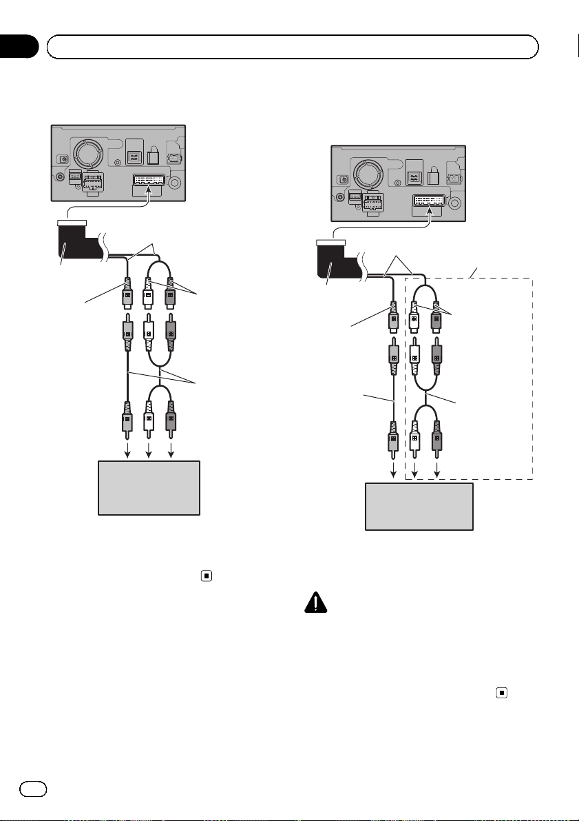
When connecting the
external video component
Using “AV1 Input” (AV1)
The navigation unit
2 m
USB and
mini-jack connector
CD-RM10
(sold separately)
Yellow
Red, white
CAUTION
Be sure to use a CD-RM10 (sold separately) for
wiring. If you use other cables, there is a case
where wiring position differs, images and sounds
may be disturbed.
OK
L : Left audio (White)
L
GVR
R : Right audio (Red)
L
V : Video (Yellow)
GRV
G : Earth
Section
03
English
RCA cables
(sold separately)
To video output
External video
component
(sold separately)
To audio outputs
! It is necessary to set “AV1 Input” in “AV
Settings” to “Video” when connecting the
external video component. (For details,
refer to Operation Manual.)
Engb
17
Page 18
Section
03
Connecting the System
Using “AV2 Input” (AV2)
The navigation unit
(*1)
20 cm (*1)
23 cm (*2)
RCA connector
Yel low
(VIDEO INPUT)
To video output
External video
component
(sold separately)
! It is necessary to set “AV2 Input” in “AV
Settings” to “Video” when connecting the
external video component. (For details,
refer to Operation Manual.)
AVIC-F20BT
(*2)
AVIC-F920BT
Red, white
(AUDIO INPUT)
RCA cables
(sold separately)
To audio outputs
When connecting the rear
display
The navigation unit
This connection
15 cm
RCA connector
Yel low
(REAR MONITOR
OUTPUT)
RCA cables
(sold separately)
To video input
Rear display with
RCA input jacks
When using a rear display
connected to rear video output
is available for
AVIC-F20BT.
Red, white
(REAR MONITOR
OUTPUT)
RCA cables
(sold separately)
To audio inputs
18
WARNING
NEVER install the rear display in a location
that enables the driver to watch the video
source while driving.
This navigation system’s rear video output is for
connection of a display to enable passengers in
the rear seats to watch the video source.
Engb
Page 19
Connecting the System
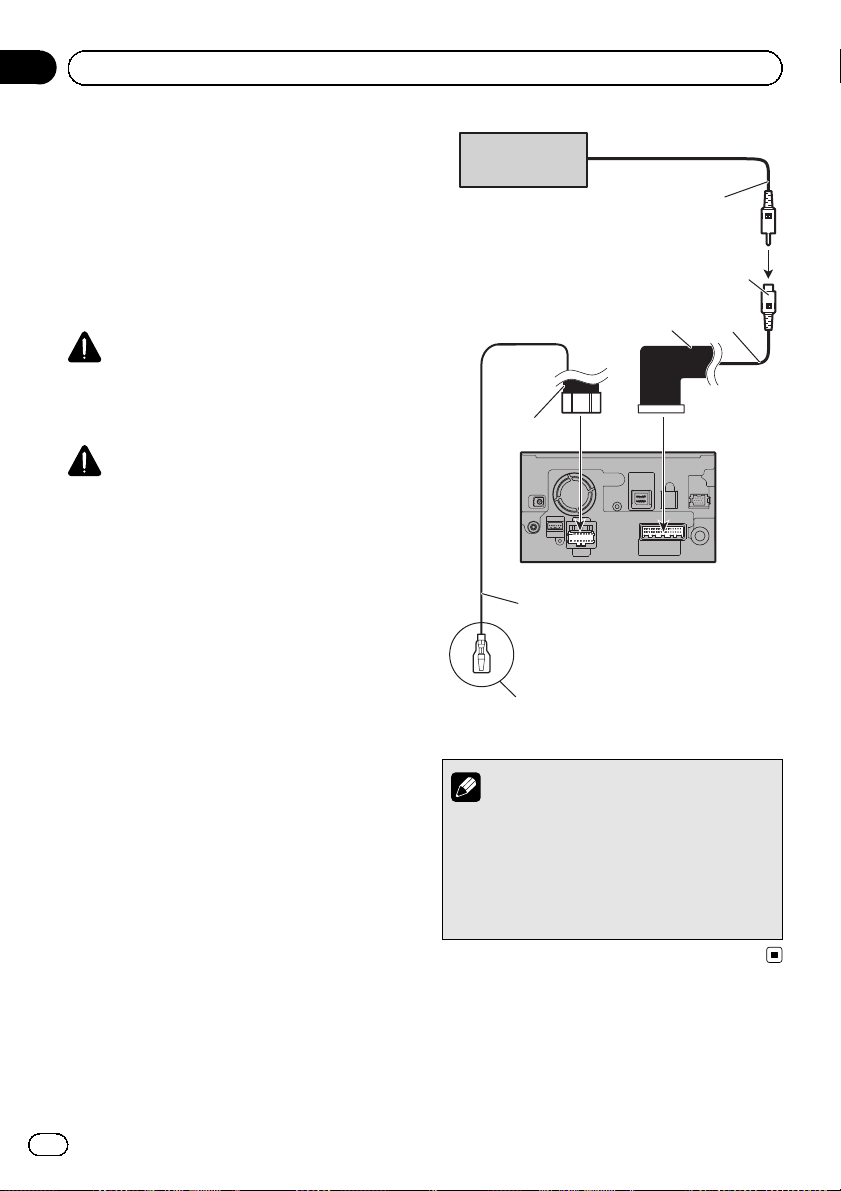
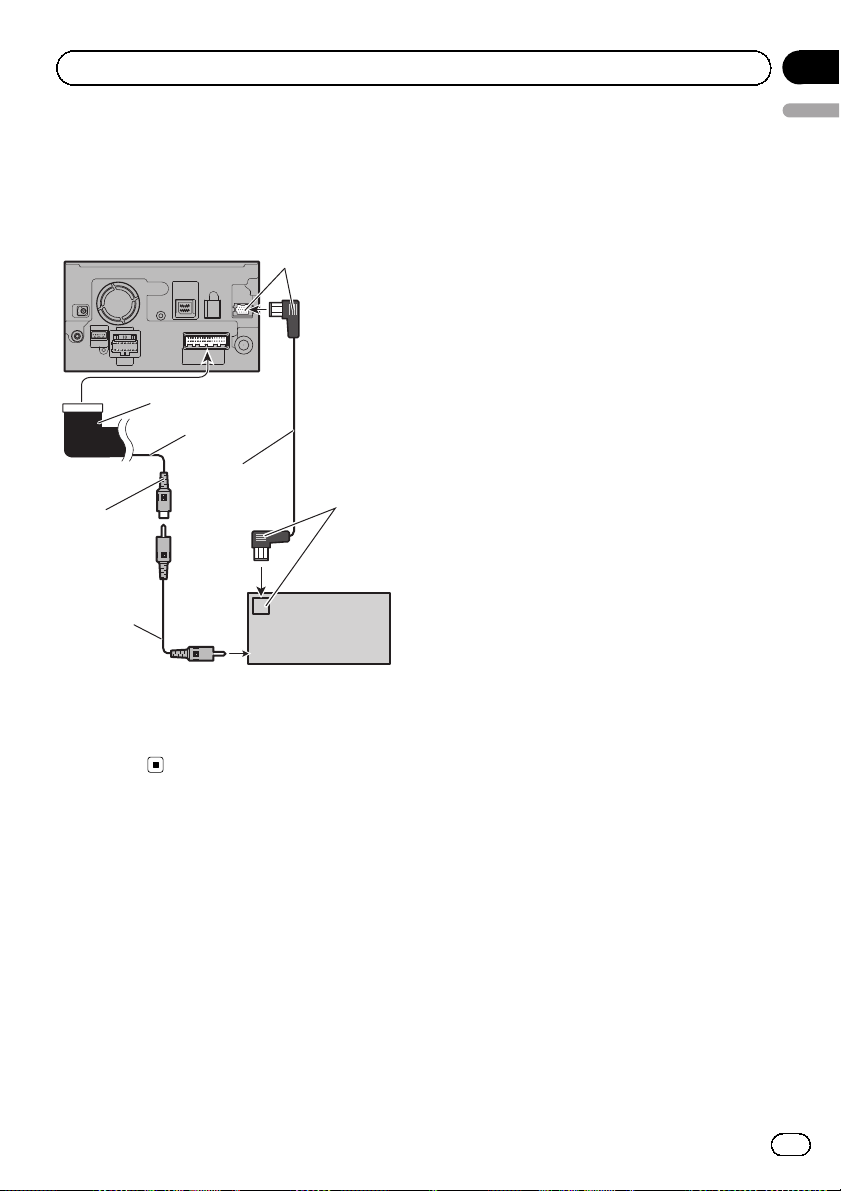
When connecting the external
unit featuring video source
p This connection is available for the AVIC-
F20BT.
The navigation unit
RCA connector
20 cm
IP-BUS cable
Yel low
(VIDEO INPUT)
RCA cable
(sold separately)
To video output
(sold separately)
To IP-BUS
output
! It is necessary to set “AV2 Input” in “AV
Settings” to “EXT” when connecting the ex-
ternal unit. (For details, refer to Operation
Manual.)
Blue
Black
Pioneer external unit
(sold separately)
Section
03
English
Engb
19
Page 20

Section
04
Installation
Precautions before
installation
CAUTION
! Never install this product in places where,
or in a manner that:
— It could injure the driver or passengers
if the vehicle stops suddenly.
— It may interfere with the driver’s opera-
tion of the vehicle, such as on the floor
in front of the driver’s seat, or close to
the steering wheel or gearstick.
! Make sure there is nothing behind the
dashboard or panelling when drilling
holes in them. Be careful not to damage
fuel lines, brake lines, electronic components, communication wires or power
cables.
! When using screws, do not allow them to
come into contact with any electrical lead.
Vibration may damage wires or insulation,
leading to a short circuit or other damage
to the vehicle.
! To ensure proper installation, use the sup-
plied parts in the manner specified. If any
parts other than the supplied ones are
used, they may damage internal parts of
this product or they may work loose and
the product may become detached.
! It is extremely dangerous to allow the
cables to become wound around the steering column or gearstick. Be sure to install
this product, its cables, and wiring away
in such a way that they will not obstruct
or hinder driving.
! Make sure that leads cannot get caught in
a door or the sliding mechanism of a seat,
resulting in a short circuit.
! Please confirm the proper function of
your vehicle’s other equipment following
installation of the navigation system.
! Do not install this navigation system
where it may (i) obstruct the driver’s vision, (ii) impair the performance of any of
the vehicle’s operating systems or safety
features, including airbags, hazard lamp
buttons or (iii) impair the driver’s ability
to safely operate the vehicle.
! Install the navigation system between the
driver’s seat and front passenger seat so
that it will not be hit by the driver or passenger if the vehicle stops quickly.
! Never install the navigation system in
front of or next to the place in the dash,
door, or pillar from which one of your vehicle’s airbags would deploy. Please refer to
your vehicle’s owner’s manual for reference to the deployment area of the frontal
airbags.
To guard against
electromagnetic interference
In order to prevent interference, set the following items as far as possible from this navigation system, other cables or leads:
! FM, MW/LW aerial and its lead
! GPS aerial and its lead
In addition you should lay or route each aerial
lead as far as possible from other aerial leads.
Do not bind them together, lay or route them
together, or cross them. Such electromagnetic
noise will increase the potential for errors in
the location display.
Before installing
! Consult with your nearest dealer if installa-
tion requires the drilling of holes or other
modifications of the vehicle.
! Before making a final installation of this
product, temporarily connect the wiring to
confirm that the connections are correct
and the system works properly.
20
Engb
Page 21
Installation
Section
04
For AVIC-F20BT users
! Do not install this navigation system in a
position where the opening of the LCD
panel is obstructed by any obstacles, such
as the gearstick. Before installing this navigation system, be sure to leave sufficient
space so that the LCD panel does not obstruct the gearstick when it is fully opened.
This may cause interference with the gearstick, or a malfunction of the mechanism
of this navigation system.
Installing this navigation
system
Installation notes
! Do not install this navigation system in
places where it may become subject to
high temperatures or humidity, such as:
— Places close to a heater, vent or air con-
ditioner.
— Places exposed to direct sunlight, such
as on top of the dashboard.
— Places that may be splashed by rain, for
example close to the door.
! Install this navigation system in an area
strong enough to bear its weight. Choose a
position where this navigation system can
be firmly installed, and install it securely. If
this navigation system is not securely installed, the current location of the vehicle
cannot be displayed correctly.
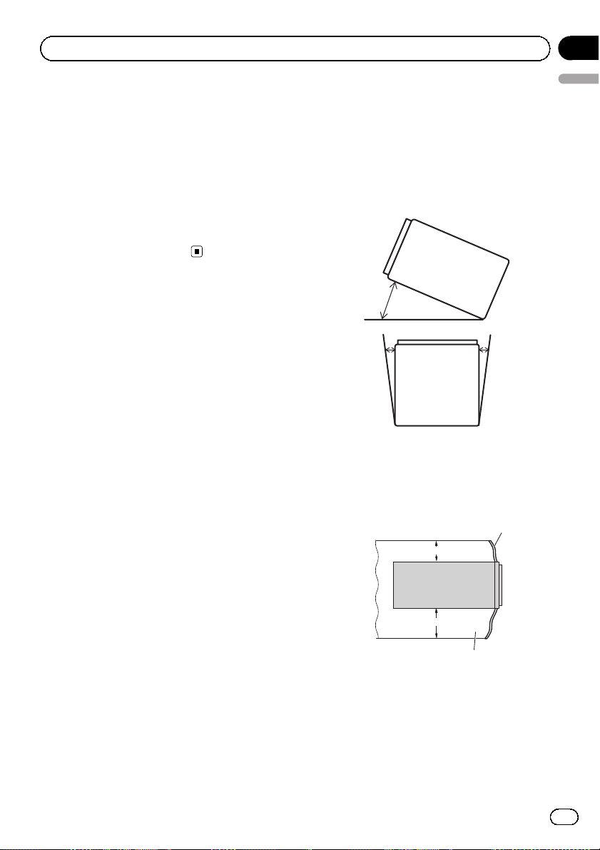
! Install the navigation unit horizontally on a
English
surface within 0 degrees to 30 degrees tolerance (within 5 degrees to the left or
right). Improper installation of the unit with
the surface tilted more than these tolerances increases the potential for errors in
the location display, and might otherwise
cause reduced display performance.
30°
5° 5°
! When installing, to ensure proper heat dis-
persal when using this unit, make sure you
leave ample space behind the rear panel
and wrap any loose cables so they are not
blocking the vents.
Dashboard
5 cm
10 cm
Leave ample space
Engb
21
Page 22
Section
04
Installation
! The cords must not cover up the area
shown in the figure below. This is necessary to allow the amps and navigation mechanism to dissipate heat.
Do not cover this area.
! The semiconductor laser will be damaged
if it overheats, so don’t install the navigation unit anywhere hot —for instance, near
a heater outlet.
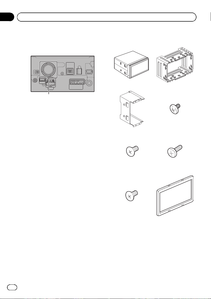
Parts supplied
Parts marked (*) are pre-installed.
The navigation unit Holder*
Side bracket*
(2 pcs.)
Flush surface screw
(5 mm × 8 mm)
(4 pcs.)
Binding screw
(5 mm × 8 mm)
(3 mm × 6 mm)
(8 pcs.)
Screw*
(8 pcs.)
22
Engb
Screw for fixing the
side bracket*
(5 mm × 8 mm)
(4 pcs.)
Trim ring*
Page 23
Installation
Section
04
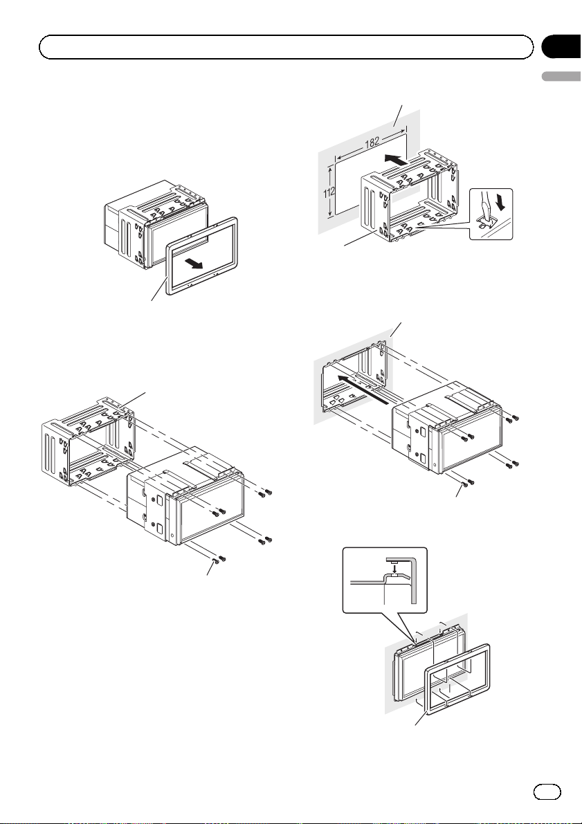
Before installing this
navigation unit
1 Remove the trim ring.
Extend top and bottom of the trim ring outwards to remove the trim ring.
Trim ring
2 Remove the holder.
Loosen the screws (3 mm × 6 mm) to remove
the holder.
Holder
Dashboard
English
Holder
2 Install this navigation unit and fasten
the screws.
Dashboard
Screw (3 mm × 6 mm)
Installation with the holder
and side bracket
1 Install the holder into the dashboard.
After inserting the holder into the dashboard,
select and bend the tabs appropriate to the
thickness of the dashboard material. (Install
this navigation unit as firmly as possible using
the top and bottom tabs. To secure this navigation unit, bend the tabs 90 degrees.)
3 Attach the trim ring.
Trim ring
Screw (3 mm × 6 mm)
Engb
23
Page 24
Section
04
Installation
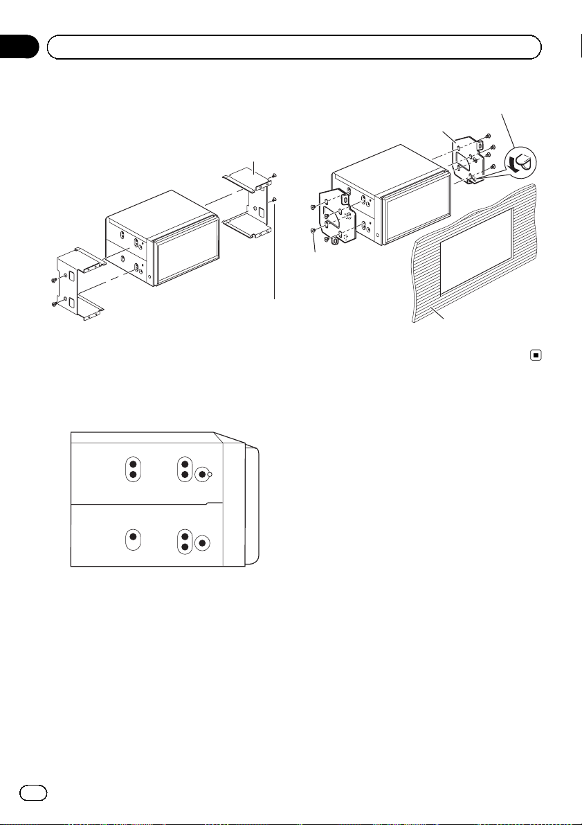
Installation using the screw holes
on the side of the navigation unit
1 Remove the side brackets.
Side bracket
Screw for fixing the side bracket
(5 mm 8 mm)
2 Fastening the navigation unit to the
factory radio-mounting bracket.
Position the navigation unit so that its screw
holes are aligned with the screw holes of the
bracket, and tighten the screws at 3 or 4 locations on each side.
Factory radio mounting bracket
Binding screw or
flush surface screw
Be sure to use the
screws supplied
with this navigation
system.
If the pawl gets in the
way, bend it down
Dashboard or console
24
Engb
Page 25

Installation
Installing the GPS aerial
CAUTION
Do not cut the GPS aerial lead to shorten it
or use an extension to make it longer. Altering the aerial cable could result in a short circuit or malfunction and permanent damage
to the navigation system.
Installation notes
! The aerial should be installed on a level sur-
face where radio waves will be blocked as
little as possible. Radio waves cannot be received by the aerial if reception from the satellite is blocked.
Section
04
English
Parts supplied
GPS aerial Metal sheet
Dashboard Rear shelf
! When installing the GPS aerial inside the
vehicle, be sure to use the metal sheet provided with your system. If this is not used,
the reception sensitivity will be poor.
! Do not cut the accessory metal sheet. This
would reduce the sensitivity of the GPS aerial.
! Take care not to pull the aerial lead when
removing the GPS aerial. The magnet attached to the aerial is very powerful, and
the lead may become detached.
! Do not paint the GPS aerial, as this may af-
fect its performance.
Engb
25
Page 26
Section
04
Installation
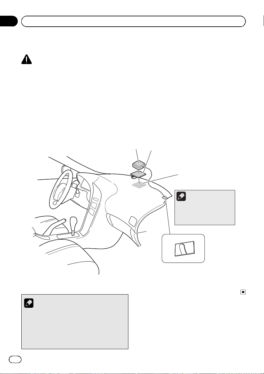
When installing the aerial inside the vehicle (on the dashboard or
rear shelf)
WARNING
Do not install the GPS aerial over any sensors or vents on the dashboard of the vehicle,
as doing so may interfere with the proper
functioning of such sensors or vents and may
compromise the ability of the metal sheet
under the GPS aerial to properly and securely affix to the dashboard.
Affix the metal sheet on as level a surface as
possible where the GPS aerial faces the window. Place the GPS aerial on the metal sheet.
(The GPS aerial is fastened with its magnet.)
GPS aerial
Metal sheet
Peel off the protective sheet
on the rear.
Make sure the surface is
free of moisture, dust,
grime, oil, etc., before
affixing the metal sheet.
Notes
! When attaching the metal sheet, do not cut
it into small pieces.
! Some models use window glass that does
not allow signals from GPS satellites to
pass through. On such models, install the
GPS aerial on the outside of the vehicle.
26
Engb
Note
The metal sheet contains a
strong adhesive which may
leave a mark on the surface if
it is removed.
Clamps
Use separately sold clamps
to secure the lead where necessary
inside the vehicle.
Page 27
Installation
Section
04
Installing the microphone
! Install the microphone in a place where its
direction and distance from the driver
make it easiest to pick up the driver’s voice.
! Make sure to connect the microphone to
the navigation system after the system is
turned off. (ACC OFF)
Parts supplied
Microphone Microphone clip
Double-sided tape
Mounting on the sun visor
1 Install the microphone in the microphone clip.
Microphone clip Microphone
2 Attach the microphone clip to the sun
English
visor.
Microphone clip
Clamps
Use separately sold clamps
to secure the lead where necessary inside the vehicle.
Install the microphone on the sun visor when
it is in the up position. It cannot recognise the
driver’s voice if the sun visor is in the down position.
Engb
27
Page 28

Section
04
Installation
Installation on the steering column
% Mount the microphone on the steering
column.
Double-sided tape
Install the microphone on the
steering column, keeping it away
from the steering wheel.
Adjusting the microphone angle
The microphone angle can be adjusted.
28
Clamps
Use separately sold
clamps to secure the
lead where necessary inside the vehicle.
Engb
Page 29

Índice
Español
INFORMACIÓN IMPORTANTE
ACERCA DE SU NUEVO SISTEMA DE
NAVEGACIÓN Y ESTE MANUAL 30
PRECAUCIONES IMPORTANTES
LEA TODAS ESTAS INSTRUCCIONES
RELACIONADAS CON SU SISTEMA DE
NAVEGACIÓN Y GUÁRDELAS PARA
EMPLEARLAS COMO REFERENCIA EN EL
FUTURO 31
Conexión del sistema
Precauciones antes de conectar el
sistema 32
Antes de instalar este producto 32
Para impedir daños 33
– Aviso para el cable conductor azul/
blanco 33
Partes suministradas 34
– AVIC-F20BT 34
– AVIC-F920BT 34
Conexión del sistema 36
Conexión del cable de alimentación (1) 38
Conexión del cable de alimentación (2) 40
Conexión al amplificador de potencia que se
vende por separado 42
Conexión de una cámara para visión
trasera 44
Al conectar el componente de vídeo
externo 45
– Utilización de “Entrada AV1” (AV1) 45
– Utilización de “Entrada AV2” (AV2) 46
Al conectar la pantalla posterior 46
– Al usar una pantalla posterior
conectada a la salida de vídeo
trasera 46
Al conectar la unidad externa con fuente de
vídeo 47
Instalación
Precauciones antes de la instalación 48
Para impedir que se produzcan
interferencias electromagnéticas 48
Antes de la instalación 49
– Para usuarios AVIC-F20BT 49
Instalación de este sistema de
navegación 49
– Notas acerca de la instalación 49
– Partes suministradas 50
– Antes de instalar esta unidad de
navegación 51
– Instalación con el soporte y el soporte
lateral 51
– Instalación utilizando los orificios del
tornillo al lado de la unidad de
navegación 52
Instalación de la antena GPS 53
– Notas acerca de la instalación 53
– Partes suministradas 53
– Cuando instale la antena en el interior
del vehículo (en el salpicadero o en la
bandeja trasera) 54
Instalación del micrófono 55
– Partes suministradas 55
– Montaje en el parasol 55
– Instalación en la columna de
dirección 56
– Ajuste del ángulo del micrófono 57
29
Es
Page 30

Sección
01
INFORMACIÓN IMPORTANTE
ACERCA DE SU NUEVO
SISTEMA DE NAVEGACIÓN Y
ESTE MANUAL
! Las funciones de navegación de este pro-
ducto (y de la opción de cámara para visión
trasera si se ha adquirido) están pensadas
únicamente para ayudarle en el manejo de
su vehículo. De ninguna forma deben considerarse como un sustituto de su atención, buen juicio y cuidado durante la
conducción.
! Nunca utilice este sistema de navegación
para guiarse hasta hospitales, comisarías
de policía o instalaciones parecidas si se
produce una emergencia. En tal caso,
llame al número de emergencias correspondiente.
! No utilice el sistema de navegación (o la
opción de cámara para visión trasera, si
dispone de ella) si le puede distraer o impedir que conduzca de manera segura. Cumpla siempre las normas de seguridad para
la conducción y respete todas las regulaciones de tráfico existentes. Si tiene problemas al manejar el sistema o al leer la
pantalla, aparque el vehículo en un lugar
seguro y ponga el freno de mano antes de
realizar los ajustes necesarios.
! Este manual explica cómo instalar este sis-
tema de navegación en su vehículo. El funcionamiento del mismo se explica en los
manuales del sistema de navegación, que
se entregan por separado.
! No instale este producto en puntos en los
que pueda (i) dificultar la visión del conductor, (ii) comprometer el funcionamiento
de alguno de los sistemas de seguridad del
vehículo, como los airbags, los botones de
los indicadores de peligro, o (iii) comprometer la capacidad del conductor para manejar el vehículo con seguridad. En
algunos casos, es posible que este producto no pueda instalarse debido al tipo de vehículo o a la forma del interior del
vehículo.
30
Es
Page 31

PRECAUCIONES IMPORTANTES
Sección
02
ADVERTENCIA
Pioneer aconseja que no realice usted mismo
la instalación del sistema de navegación. Recomendamos que sólo el personal de servicio
autorizado de Pioneer, que cuenta con formación especializada y experiencia en el campo
de la electrónica móvil, instale y configure
este producto. NUNCA EFECTÚE EL MANTENIMIENTO DE ESTE PRODUCTO USTED
MISMO. La instalación o el mantenimiento
del producto y de los cables de conexión asociados puede exponerle al riesgo de una descarga eléctrica u otros peligros, y puede
ocasionar daños en el sistema de navegación
que no cubre la garantía.
LEA TODAS ESTAS
INSTRUCCIONES
RELACIONADAS CON SU
SISTEMA DE NAVEGACIÓN Y
GUÁRDELAS PARA
EMPLEARLAS COMO
REFERENCIA EN EL FUTURO
1 Lea completa y detenidamente este manual
antes de instalar su sistema de navegación.
2 Guarde al alcance de la mano este manual
para utilizarlo como referencia en el futuro.
3 Ponga mucha atención a todas las adverten-
cias de este manual y siga cuidadosamente
las instrucciones.
4 En ciertas circunstancias, este sistema de na-
vegación puede mostrar una información
errónea de la posición de su vehículo, la distancia de los objetos mostrados en la pantalla
y las direcciones de la brújula. Además, el sistema tiene ciertas limitaciones, incluyendo la
incapacidad de identificar calles de una dirección, restricciones temporales de tráfico y
zonas donde la conducción pueda resultar peligrosa. Haga uso de su buen juicio en función de las condiciones de conducción reales.
5 Al igual que con cualquier otro accesorio del
interior, el sistema de navegación nunca deberá distraerle ni poner en peligro el manejo seguro de su vehículo. Si encuentra dificultades
al utilizar el sistema o al leer la pantalla, haga
los ajustes necesarios con el vehículo estacionado en un lugar seguro.
6 Recuerde ponerse siempre el cinturón de se-
guridad cuando maneje su vehículo. En el
caso de sufrir un accidente, sus lesiones pueden ser mucho más graves si no tiene bien
puesto su cinturón de seguridad.
7 Algunos países y leyes gubernamentales pue-
den prohibir o limitar la ubicación y el uso de
este sistema en su vehículo. Cumpla con
todas las leyes y normas pertinentes en cuanto al uso, la instalación y el funcionamiento
del sistema de navegación.
Español
31
Es
Page 32

Sección
03
Conexión del sistema
Precauciones antes de
conectar el sistema
PRECAUCIÓN
! Si decide efectuar la instalación usted
mismo y cuenta con formación especializada y experiencia en la instalación de sistemas electrónicos móviles, siga con
cuidado todos los pasos descritos en el
manual de instalación.
! Asegure todo el cableado con abrazaderas
de cables o cinta para usos eléctricos. No
permita que el cableado pelado permanezca descubierto.
! No enchufe directamente el cable amarillo
de este producto a la batería del vehículo.
Si lo hace, puede que la vibración del
motor acabe provocando un problema relacionado con el aislamiento en el punto
por donde el cable cruza del compartimiento del pasajero al compartimiento
del motor. Si se rompe el aislamiento del
cable amarillo como resultado del contacto con partes metálicas, puede producirse
un cortocircuito y generar por tanto un peligro considerable.
! Es extremamente peligroso permitir que
los cables queden enrollados alrededor de
la columna de la dirección o palanca de
cambio. Asegúrese de instalar este producto, sus cables y hilos alejados, de
forma que no obstruyan o impidan la conducción del vehículo.
! Asegúrese de que todos los cables estén
enrutados y sujetos de manera que no entorpezcan o queden atrapados con alguna
de las partes móviles del vehículo, en especial con el volante, la palanca de cambio, el freno de mano, las guías de los
asientos deslizantes, las puertas o con alguno de los controles del vehículo.
! No enrute cables que vayan a estar some-
tidos a altas temperaturas. Si se calienta
el aislamiento, los cables pueden resultar
dañados y, como consecuencia, puede
producirse un cortocircuito o una avería y
el producto puede sufrir un deterioro permanente.
! No corte el cable de la antena GPS para
reducir su longitud ni utilice una extensión para alargarlo. La alteración del cable
de la antena puede causar un cortocircuito.
! No acorte ningún cable. En el caso de que
lo haga, el circuito de protección (el portafusibles, la resistencia de fusible o el filtro, etc.) puede que no funcione
correctamente.
! Nunca suministre alimentación a otros
productos electrónicos cortando el aislamiento del cable de alimentación del sistema de navegación y tomando corriente
de él. La capacidad nominal del cable se
excederá y causará un recalentamiento.
Antes de instalar este
producto
! Utilice esta unidad solamente con una ba-
tería de 12 voltios y puesta a tierra negativa.
De lo contrario, podrá ocasionar un incendio o un fallo de funcionamiento.
! Para evitar cortocircuitos en el sistema
eléctrico, asegúrese de desconectar el
cable de la batería (–) antes de comenzar
con la instalación.
32
Es
Page 33

Conexión del sistema
Sección
03
Para impedir daños
ADVERTENCIA
! Utilice altavoces con capacidad superior a
50 W (valor de salida) y entre 4W a8W
(valor de impedancia). No utilice altavoces de 1 W a3W para esta unidad.
! El cable negro es de conexión a tierra. Co-
necte este cable a una toma de tierra distinta de productos de alta tensión, como,
por ejemplo, amplificadores de potencia.
No conecte a tierra más de un componente junto con la conexión a tierra de otro
componente. Por ejemplo, debe conectar
a tierra por separado cualquier unidad de
amplificador y este sistema de navegación. La conexión conjunta de la tierra de
uno y otro puede ocasionar un incendio y/
o dañar los productos si se desprende la
tierra de cada uno.
! Al sustituir el fusible, asegúrese de utili-
zar exclusivamente un fusible del régimen
nominal descrito en este producto.
! Cuando desconecte un conector, tire del
propio conector. No tire del cable porque
podría sacarlo del conector.
! No se puede instsalar este producto en un
vehículo sin la posición ACC (accesorio)
en el interruptor de encendido.
C
C
A
O
F
N
F
O
Posición ACC Sin posición ACC
S
T
A
R
T
! Para evitar cortocircuitos, cubra el conduc-
tor desconectado con cinta aislada. Es especialmente importante aislar todos los
cables de altavoz que no se usen, ya que si
no se recubren pueden llegar a provocar
un cortocircuito.
! Acople los conectores de un color determi-
nado al puerto correspondiente del mismo
O
F
N
F
O
S
T
A
R
T
color, es decir, el conector azul al puerto
azul, el conector negro al puerto negro, etc.
! Consulte el manual del propietario para ob-
tener información sobre la conexión del
amplificador de potencia y de otras unidades y, a continuación, realice las conexiones de manera acorde.
! Como se utiliza un circuito BPTL único, no
conecte directamente a tierra el extremo *
del cable del altavoz, ni conecte juntos los
extremos * de los cables de los altavoces.
Asegúrese de conectar el extremo * del
cable del altavoz al extremo * del cable
del altavoz de este sistema de navegación.
! Si no va a utilizarse la clavija RCA en este
producto, no retire las tapas del extremo
del conector.
Aviso para el cable conductor
azul/blanco
! Al conectar el interruptor de encendido
(ACC ON), se envía una señal de control
por el cable azul/blanco. Conéctelo al terminal de control remoto del sistema externo de amplificadores de potencia, al
terminal de control de relé de la antena
automática, o al terminal de control de potencia del amplificador de antena (máx.
300 mA 12 V CC). La señal de control se
envía por el cable azul/blanco, aunque la
fuente de audio esté desconectada.
! Asegúrese de utilizar este cable conductor
como el cable conductor del suministro de
energía para los amplificadores de potencia externos. Tal conexión podría causar un
drenaje excesivo de corriente y un fallo de
funcionamiento.
! Asegúrese de utilizar este cable conductor
como el cable conductor del suministro de
energía para la antena automática o amplificador de antena. Tal conexión podría causar un drenaje excesivo de corriente y un
fallo de funcionamiento.
Español
33
Es
Page 34

Sección
03
Conexión del sistema
Partes suministradas
AVIC-F20BT
AVIC-F920BT
La unidad de navega-
ción
Sintonizador RDS-TMC Conector USB y mini-
Conector RCA Antena GPS
Micrófono
Cable de alimentación
jack
La unidad de navega-
ción
Sintonizador RDS-TMC Conector USB y mini-
Conector RCA Antena GPS
Micrófono
Cable de alimentación
jack
34
Es
Page 35

Conexión del sistema
Sección
03
Español
35
Es
Page 36

Sección
03
Conexión del sistema
Conexión del sistema
3,55 m
Verde
WIRED REMOTE INPUT
Consulte el Manual de instrucciones
para los adaptadores de control remoto
alámbrico (se venden por separado).
La unidad de navegación
30 cm
Antena del
vehículo
Toma de
antena
Sintonizador
RDS-TMC
1 m
2 m
(*2)
Conector IP-BUS
(El conector IP-BUS está
disponible para
AVIC-F20BT.)
Conector USB y
minijack
(*1)
Conecte el cable de
interfaz USB para
iPod o un dispositivo
de almacenamiento
USB apropiado.
(*1)
36
(*2)
— Cuando conecte su iPod, ambas conexiones son necesarias.
— Al conectar el iPod, se debe ajustar “Entrada AV1” en “Conf. sistema
AV” a “iPod”. (Para los detalles, consulte el Manual de operación.)
Es
Page 37

Conexión del sistema
Sección
03
Antena GPS
Micrófono
4 m
ADVERTENCIA
· Para evitar el riesgo de accidente y la posible violación de las leyes aplicables,
nunca se debe utilizar este producto mientras se conduce el vehículo, excepto
para la finalidad de navegación. Además, no se debe posicionar la pantalla
trasera donde la misma pueda presentar una distracción visible al conductor.
· En algunos países, la visualización de imágenes en una pantalla dentro de un
vehículo, aún por los pasajeros, puede ser ilegal. Cuando aplicables, se debe
obedecer tales reglamentos y no se debe utilizar la fuente de vídeo de este
producto.
iPod con conector de
acoplamiento(*3)
(*3)
Para los detalles sobre las
operaciones y la compatibilidad,
consulte el Manual de operación.
Puerto de
conector de
acoplamiento
Cable de interfaz USB para
iPod (CD-IU50V) (se vende por
separado)
Español
37
Es
Page 38

Sección
03
Conexión del sistema
Conexión del cable de alimentación (1)
Nota
Según cual sea el tipo de vehículo, la función
de *2 y *4 puede variar. En tal caso, asegúrese
de conectar *1 a *4 y *3 a *2.
*2
*4
Amarillo (*2)
Reserva
(o accesorio)
Rojo (*4)
Accesorio
(o reserva)
*1
*3
Amarillo (*1)
Al terminal, siempre dispone de
alimentación independientemente de la
posición del interruptor de encendido.
Rojo (*3)
Al terminal eléctrico que controla el
interruptor de encendido (12 V CC)
ON/OFF.
Anaranjado/blanco
Al terminal del interruptor de iluminación.
Notas
· Al conectar a este sistema de navegación un
subwoofer (*5) en lugar de un altavoz trasero,
cambie el ajuste de salida trasera en Ajustes
iniciales. (Consulte el Manual de operación.) La
salida del altavoz de graves de este sistema de
navegación es monoaural.
· Al utilizar un altavoz de graves de 70 W (2 Ω),
asegúrese de conectar con los cables violeta y
violeta/negro de esta unidad de navegación. No
conecte nada con cables verde y verde/negro.
Conecte los cables del
mismo color entre ellos.
38
Negro (tierra)
A la carrocería (metálica)
del vehículo.
Conector ISO
Cables de altavoz
Blanco: Izquierdo delantero
Blanco/negro: Izquierdo delantero
Gris: Derecho delantero
Gris/negro: Derecho delantero
Verde: Izquierdo trasero o Altavoz de graves (*5)
Verde/negro: Izquierdo trasero o Altavoz de graves (*5)
Violeta: Derecho trasero o Altavoz de graves (*5)
Violeta/negro: Derecho trasero o Altavoz de graves (*5)
Es
Page 39

Conexión del sistema
La unidad de navegación
Sección
03
Conector RCA
Cable de
alimentación
Amarillo/negro
Si utiliza un equipo con una función de silencio, conecte ese equipo al cable
de silencio de audio. Si no, deje ese cable sin conexión.
15 cm
Nota
La fuente de audio se silenciará o atenuará, mientras que los sonidos
siguientes no se silenciarán ni atenuarán. Para los detalles, consulte el
Manual de operación.
— guía de voz del sistema de navegación
— timbre entrante y voz entrante del teléfono móvil conectado al sistema
de navegación a través de la tecnología inalámbrica Bluetooth
Fusible (10 A)
Español
Azul/blanco (*6)
La posición de la clavija del conector ISO variará en función
del tipo de vehículo. Conecte *6 y *7 cuando la clavija 5 sea
del tipo de control de antena. En otros tipos de vehículo,
nunca conecte *6 y *7.
Azul/blanco (*7)
Al terminal de control del relé de la antena
automática (máx. 300 mA 12 V CC).
39
Es
Page 40

Sección
03
Conexión del sistema
Conexión del cable de alimentación (2)
Rosado (CAR SPEED SIGNAL INPUT)
El sistema de navegación móvil se conecta aquí para detectar la distancia que ha recorrido el
vehículo. Conecte siempre el circuito de detección de velocidad del vehículo. Si no se hace esta
conexión, aumentará el error en la visualización de ubicación.
ADVERTENCIA
UNA MALA CONEXIÓN PUEDE OCASIONAR DAÑOS O LESIONES GRAVES, COMO DESCARGAS
ELÉCTRICAS, Y AFECTAR AL FUNCIONAMIENTO DEL SISTEMA DE ANTIBLOQUEO DE FRENOS DEL
VEHÍCULO, A LA CAJA DE CAMBIOS AUTOMÁTICA Y AL INDICADOR DEL VELOCÍMETRO DEL VEHÍCULO.
PRECAUCIÓN
Se recomienda encarecidamente que mantenga el cable de impulsos de velocidad
conectado para garantizar la precisión de la navegación y un mejor rendimiento.
Nota
La posición del circuito de detección de velocidad y la posición del interruptor de freno de
aparcamiento dependen del modelo del vehículo. Para más información, pregunte a su
distribuidor autorizado de Pioneer o a un instalador profesional.
Verde claro (PARKING BRAKE)
Se utiliza para detectar el estado ON/OFF del freno de mano. Este cable debe conectarse al lado de la fuente
de alimentación del interruptor del freno de mano.
Si esta conexión se hace mal o se omite, algunas funciones de su sistema de navegación no podrán
utilizarse.
ADVERTENCIA
EL CABLE VERDE CLARO EN EL CONECTOR DE
ALIMENTACIÓN ESTÁ DISEÑADO PARA DETECTAR EL
ESTADO DE ESTACIONAMIENTO Y DEBE CONECTARSE
AL LADO DE LA FUENTE DE ALIMENTACIÓN DEL
INTERRUPTOR DEL FRENO DE MANO. UN USO O
CONEXIÓN INADECUADOS DE ESTE CABLE PUEDE
VULNERAR LA LEY CORRESPONDIENTE Y CAUSAR
DAÑOS O HERIDAS GRA VES.
Método de conexión
Apriete el cable del lado de
40
alimentación del interruptor del
freno de mano.
Apriete firmemente con alicates
de punta de aguja.
Es
Lado de alimentación
Lado de tierra
Interruptor del freno de mano
Page 41

Conexión del sistema
Sección
03
Español
La unidad de navegación
Cable de
alimentación
Violeta/blanco
Ésta se conecta para que el sistema de navegación pueda
detectar si el automóvil está moviéndose hacia adelante o
hacia atrás. Conecte el cable violeta/ blanco al cable cuya
tensión cambia cuando la palanca de cambios se pone en
la posición de marcha atrás. A menos que esté conectado,
puede que el sensor no detecte de forma correcta si su
vehículo se desplaza hacia adelante o hacia atrás. Por ello,
es posible que la posición del vehículo que detecta el
sensor esté desalineada respecto a la posición real.
(REVERSE GEAR SIGNAL INPUT)
Nota
Cuando utilice una cámara para visión trasera,
asegúrese de conectar este cable. De lo
contrario, no podrá cambiar a la imagen de la
cámara para visión trasera.
41
Es
Page 42

Sección
03
Conexión del sistema
Conexión al amplificador de potencia que se vende por separado
Salida de altavoz de graves
(SUBWOOFER OUTPUT)
25 cm (*1)
Conector RCA
La unidad de navegación
Cable de
alimentación
31 cm (*2)
Salida trasera
(REAR OUTPUT)
30 cm (*1)
15 cm (*2)
Salida delantera
(FRONT OUTPUT)
30 cm (*1)
15 cm (*2)
(*1)
AVIC-F20BT
Azul/blanco
Al terminal de control del sistema del
amplificador de potencia (máx. 300 mA 12 V CC).
(*2)
AVIC-F920BT
42
Es
Page 43

Conexión del sistema
Cables RCA
(en venta por separado)
Control remoto de sistema
Sección
03
Amplificador de
potencia (en venta
por separado)
Español
Amplificador de
potencia (en venta
por separado)
Amplificador de
potencia (en venta
por separado)
Izquierda Derecha
Altavoz
delantero
Altavoz
trasero
Altavoz de
graves
Altavoz
delantero
Altavoz
trasero
Altavoz de
graves
Nota
Puede cambiar la salida RCA del altavoz de graves segun su sistema de
altavoces de graves (consulte Manual de operacion).
43
Es
Page 44

Sección
03
Conexión del sistema
Conexión de una cámara
para visión trasera
Cuando se utiliza este producto con una cámara de retrovisor, se puede cambiar automáticamente de la imagen de vídeo a la imagen
de vista trasera cuando se desplaza la palanca
de cambio al modo de marcha atrás (R). El
modo Vista posterior también le permite verificar lo que está detrás mientras conduce vehículo.
ADVERTENCIA
USE LA ENTRADA SÓLO PARA LA MARCHA
ATRÁS O LA CÁMARA PARA VISIÓN TRASERA
DE IMAGEN ESPECULAR. CUALQUIER OTRO
USO PUEDE DERIVAR EN LESIONES O DAÑOS.
PRECAUCIÓN
! La imagen en pantalla puede aparecer inverti-
da.
! La función de la cámara para visión trasera
debe servir para el uso de este producto como
elemento de ayuda en el control de remolques, o al circular marcha atrás en una plaza
de estacionamiento estrecha. No utilice esta
función para fines recreativos.
! El objeto que aparece en la cámara puede pa-
recer más cercano o más distante de lo que
está en realidad.
! Tenga en cuenta que los bordes de las imáge-
nes que aparecen en la cámara para visión
trasera pueden variar ligeramente en función
de si se muestran imágenes en formato de
pantalla completa al circular marcha atrás, y
de si utilizan las imágenes para controlar la
parte posterior del vehículo cuando se desplaza hacia delante.
Cámara para
visión trasera
(p. ej., ND-BC4 )
(en venta por
separado)
(*1)
AVIC-F20BT
(*2)
AVIC-F920BT
Cable de
alimentación
Violeta/blanco
(REVERSE GEAR SIGNAL INPUT)
Para obtener más información sobre el cableado, consulte Conexión del cable de alimentación (2) en la página 40.
A la salida de vídeo
Cable RCA
Marrón
(REAR VIEW CAMERA IN)
Conector RCA
La unidad de navegación
20 cm (*1)
23 cm (*2)
Notas
! Al conectar la cámara para visión trasera,
se debe ajustar “Cámara” en “Config. cá-
mara trasera” a “On”. (Para los detalles,
consulte el Manual de operación.)
! Conecte a la cámara para visión trasera. No
conecte a ningún otro equipo.
44
Es
Page 45

Conexión del sistema
Sección
03
Al conectar el componente
de vídeo externo
Utilización de “Entrada AV1” (AV1)
La unidad de navegación
2 m
Conector USB y
minijack
CD-RM10
(en venta por separado)
Amarillo
Rojo, blanco
Cables RCA
(en venta por
separado)
PRECAUCIÓN
Utilice un CD-RM10 (en venta por separado) para
realizar la conexión. Si utiliza otros cables, hay un
caso en la que la posición de cableado difiere, y
las imágenes y los sonidos pueden perturbarse.
OK
L
GVR
L : Audio izquierda
(Blanco)
R : Audio derecha (Rojo)
L
V : Video (Amarillo)
GRV
G : Tierra
Español
A la salida de vídeo A las salidas
de audio
Componente de vídeo
externo (en venta por
separado)
! Al conectar el componente de vídeo exter-
no, se debe ajustar “Entrada AV1” en
“Conf. sistema AV” a “Vídeo”. (Para los
detalles, consulte el Manual de operación.)
45
Es
Page 46

Sección
03
Conexión del sistema
Utilización de “Entrada AV2” (AV2)
La unidad de navegación
(*1)
20 cm (*1)
23 cm (*2)
Conector RCA
Amarillo
(VIDEO INPUT)
A la salida de
vídeo
Componente de vídeo
externo (en venta por
separado)
! Al conectar el componente de vídeo exter-
no, se debe ajustar “Entrada AV2” en
“Conf. sistema AV” a “Vídeo”. (Para los
detalles, consulte el Manual de
operación.)
AVIC-F20BT
(*2)
AVIC-F920BT
Rojo, blanco
(AUDIO INPUT)
Cables RCA
(en venta por
separado)
A las salidas de audio
Al conectar la pantalla
posterior
La unidad de navegación
Esta conexión está
15 cm
Conector RCA
Amarillo
(REAR MONITOR
OUTPUT)
Cables RCA
(se venden por
separado)
A la entrada de
vídeo
Pantalla trasera con
tomas de entrada RCA
Al usar una pantalla posterior
conectada a la salida de vídeo
trasera
disponible para
AVIC-F20BT.
Rojo, blanco
(REAR MONITOR
OUTPUT)
Cables RCA
(se venden por
separado)
A las entradas de
audio
46
ADVERTENCIA
NUNCA instale la pantalla posterior en un
punto que permita al conductor ver la fuente
de vídeo mientras conduce.
La salida de vídeo posterior de este sistema de
navegación es para conectar una pantalla que
permita a los pasajeros de los asientos posteriores ver la fuente de vídeo.
Es
Page 47

Conexión del sistema
Al conectar la unidad
externa con fuente de vídeo
p Esta conexión está disponible para AVIC-
F20BT.
La unidad de navegación
Conector RCA
20 cm
Cable IP-BUS
(en venta por
Amarillo
(VIDEO INPUT)
Cable RCA
(en venta por
separado)
A la salida de vídeo
separado)
A la salida
IP-BUS
! Al conectar la unidad externa, se debe
ajustar “Entrada AV2” en “Conf. sistema
AV” a “EXT”. (Para los detalles, consulte el
Manual de operación.)
Azul
Negro
Unidad externa de
Pioneer (en venta por
separado)
Sección
03
Español
47
Es
Page 48

Sección
04
Instalación
Precauciones antes de la
instalación
PRECAUCIÓN
! Nunca instale este producto en lugares en
los que, o de manera que:
— Pueda lesionar al conductor o a los pa-
sajeros si el vehículo se detiene bruscamente.
— Pueda entorpecer el manejo del ve-
hículo por parte del conductor, por
ejemplo en el piso delante del asiento
del conductor o cerca del volante o de
la palanca de cambio.
! Asegúrese de que no haya nada detrás del
tablero de instrumentos u otros paneles al
taladrar agujeros en ellos. Tenga cuidado
de no dañar conductos de combustible,
tuberías de freno, componentes electrónicos, cables de alimentación y de comunicaciones.
! Cuando utilice tornillos no permita que
éstos entren en contacto con ningún cable
eléctrico. La vibración puede deteriorar
los cables o el aislamiento y provocar un
cortocircuito u otros daños en el vehículo.
! Para asegurar una instalación apropiada,
utilice las piezas suministradas de la
forma especificada. Si utiliza otras piezas
que no hayan sido suministradas, éstas
podrán estropear las partes internas del
producto, o podrán aflojarse y hacer que
se desprenda el producto.
! Es extremamente peligroso permitir que
los cables queden enrollados alrededor de
la columna de la dirección o palanca de
cambio. Asegúrese de instalar este producto, sus cables y hilos alejados, de
forma que no obstruyan o impidan la conducción del vehículo.
! Asegúrese de que los cables no queden
atrapados en una puerta ni en el mecanismo de deslizamiento de un asiento porque
puede producirse un cortocircuito.
! Después de instalar el sistema de navega-
ción, compruebe que todos los demás
equipos de su vehículo funcionan correctamente.
! No instale este sistema de navegación en
puntos en los que pueda (i) dificultar la visión del conductor, (ii) comprometer el
funcionamiento de alguno de los sistemas
de seguridad del vehículo, como los airbags, los botones de los indicadores de
peligro, o (iii) comprometer la capacidad
del conductor para manejar el vehículo
con seguridad.
! Instale el sistema de navegación entre el
asiento del conductor y el asiento del pasajero delantero de manera que no sufra
ningún golpe por parte del conductor o
del pasajero en el caso de que el vehículo
frene bruscamente.
! No instale nunca el sistema de navega-
ción en la frente o cerca del sitio en el tablero de instrumentos, puerta o pilar
donde un airbag del vehículo podría desplegarse. Consulte el manual del propietario de su vehículo para las referencias
acerca de las áreas de despliegue de los
airbags delanteros.
Para impedir que se
produzcan interferencias
electromagnéticas
Para evitar interferencias, instale los siguientes elementos lo más lejos posible del sistema
de navegación, así como de otros cables:
! La antena FM, MW/LW y su cable
! La antena GPS y su cable
Además debería colocar o enrutar cada cable
de antena lo más alejado posible de otros cables de antena. No los ate, ni los coloque o enrute juntos, ni tampoco los cruce. El ruido
electromagnético aumentará las posibilidades
de que se produzcan errores en la pantalla de
situación.
48
Es
Page 49

Instalación
Sección
04
Antes de la instalación
! Consulte con su distribuidor si la instala-
ción requiere del taladro de orificios u otras
modificaciones del vehículo.
! Antes de realizar la instalación final de este
producto, conecte el cableado temporalmente y asegúrese de que todo está conectado correctamente y que el sistema
funciona debidamente.
Para usuarios AVIC-F20BT
! No instale este sistema de navegación en
un lugar en el que la apertura del panel
LCD se vea obstruida por cualquier obstáculo, como la palanca de cambios. Antes
de instalar este sistema de navegación,
asegúrese de dejar suficiente espacio para
que el panel LCD no choque con la palanca
de cambios cuando esté totalmente abierto. Puede afectar al funcionamiento de la
palanca de cambios o impedir el correcto
funcionamiento del mecanismo de este sistema de navegación.
Instalación de este sistema
de navegación
Notas acerca de la instalación
! No instale este sistema de navegación en
sitios donde pueda estar expuesto a altas
temperaturas o a humedad, como por
ejemplo:
— Lugares cercanos a un calefactor, con-
ducto de ventilación o aire acondicionado.
— Lugares expuestos a la luz solar directa
tales como el salpicadero.
— Lugares donde pueda ser salpicada por
la lluvia como, por ejemplo, cerca de la
puerta.
! Instale este sistema de navegación en una
zona que sea lo bastante resistente para
soportar su peso. Elija un lugar donde este
sistema de navegación se pueda instalar
bien e instálelo de forma segura. Si el sistema de navegación no está bien instalado,
no se mostrará correctamente la ubicación
actual del vehículo.
! Instale la unidad de navegación de forma
horizontal sobre una superficie dentro de
un margen de tolerancia de 0 grados a 30
grados (en un margen de 5 grados a la izquierda o a la derecha). La incorrecta instalación de la unidad, con la superficie
inclinada más de lo que se indica en estas
instrucciones, aumenta la posibilidad de
que se produzcan errores en la visualización de ubicación, y podría a su vez mermar el rendimiento de la pantalla.
30°
5° 5°
! Cuando instale, para asegurar la dispersión
apropiada del calor durante el uso de esta
unidad, asegúrese de dejar un amplio espacio por detrás del panel trasero y enrolle
cualesquiera cables sueltos de modo que
no bloque en las aberturas de ventilación.
Salpicadero
5 cm
10 cm
Deje un amplio espacio
Español
49
Es
Page 50

Sección
04
Instalación
! Los cables no deben cubrir la zona que
aparece en la figura inferior. Ello es necesario para que los amplificadores y el mecanismo de navegación puedan disipar el
calor.
No cubra esta zona.
! El láser de semiconductor quedará dañado
si se sobrecalienta, por tanto no instale la
unidad de navegación en ningún sitio con
calor (por ejemplo, cerca de una salida de
calefacción).
Partes suministradas
Las piezas marcadas con un asterisco (*)
están instaladas previamente.
La unidad de navega-
ción
Soporte lateral*
(2 piezas)
Tornillo de superficie
plana
(5 mm × 8 mm)
(4 piezas)
Soporte*
Tornillo de unión
(5 mm × 8 mm)
(8 piezas)
Tornillo*
(3 mm × 6 mm)
(8 piezas)
50
Tornillo para fijar la so-
porte lateral*
(5 mm × 8 mm)
(4 piezas)
Es
Anillo embellecedor*
Page 51

Instalación
Sección
04
Antes de instalar esta unidad
de navegación
1 Extraiga el anillo embellecedor.
Extienda la parte superior y la parte inferior
del anillo embellecedor hacia fuera para extraer el anillo embellecedor.
Anillo embellecedor
2 Retire el soporte.
Afloje los tornillos (3 mm × 6 mm) para retirar
el soporte.
Soporte
Para asegurar esta unidad de navegación,
doble las pestañas 90 grados.)
Salpicadero
Español
Soporte
2 Instale esta unidad de navegación y
apriete los tornillos.
Salpicadero
Tornillo (3 mm × 6 mm)
Instalación con el soporte y el
soporte lateral
1 Instale el soporte en el salpicadero.
Tras introducir el soporte en el salpicadero, seleccione y doble las pestañas de acuerdo con
el grosor del material del salpicadero. (Instale
esta unidad de navegación lo más firme posible utilizando las pestañas superior e inferior.
Tornillo (3 mm × 6 mm)
51
Es
Page 52

T
Sección
04
Instalación
3 Coloque el anillo embellecedor.
Anillo embellecedor
Instalación utilizando los
orificios del tornillo al lado de
la unidad de navegación
1 Retire los soportes laterales.
Soporte lateral
Si el trinquete está en
medio, dóblelo hacia abajo
Soporte de montaje de radio de
fábrica
ornillo de unión o
tornillo de superficie
plana
Asegúrese de
utilizar los tornillos
proporcionados con
este sistema
de navegación.
Salpicadero o consola
Tornillo para fijar el soporte lateral
(5 mm 8 mm)
2 Fijar la unidad de navegación al soporte
de montaje de radio de fábrica.
Coloque la unidad de navegación de forma
que los orificios de su tornillo estén alineados
con los orificios del tornillo del soporte, y
apriete los tornillos en 3 o 4 lugares a cada
lado.
52
Es
Page 53

Instalación
Sección
04
Instalación de la antena GPS
PRECAUCIÓN
No corte el cable de la antena GPS para reducir su longitud, ni utilice una extensión para
alargarlo. La alteración del cable de la antena
puede provocar un cortocircuito o una avería
y daños permanentes al sistema de navegación.
Notas acerca de la instalación
! La antena debe instalarse en una superfi-
cie nivelada donde las ondas de radio queden bloqueadas lo menos posible. Las
ondas de radio no podrán ser recibidas por
la antena si la emisión desde el satélite
queda bloqueada.
Salpicadero Bandeja trasera
! Cuando instale la antena GPS en el interior
del vehículo, asegúrese de utilizar la hoja
de metálica proporcionada con su sistema.
Si ésta no se utiliza, la sensibilidad de la recepción no será apropiada.
! No corte la hoja de metálica suministrada
para hacerla más pequeña. Esto podría reducir la sensibilidad de la antena GPS.
! Tenga cuidado de no tirar del cable de la
antena cuando quite la antena GPS. El
imán colocado en la antena es muy potente y es posible que el cable se desprenda.
! No pinte la antena GPS ya que puede alte-
rar su rendimiento.
Partes suministradas
Antena GPS Hoja de metal
Español
53
Es
Page 54

Sección
04
Instalación
Cuando instale la antena en el interior del vehículo (en el
salpicadero o en la bandeja trasera)
ADVERTENCIA
No instale la antena GPS sobre sensores o
aberturas de ventilación en el tablero de instrumentos del vehículo, ya que eso puede interferir con el funcionamiento apropiado de
tales sensores o aberturas de ventilación y
puede comprometer la habilidad de adherencia apropiada y segura de la hoja de metal
por debajo de la antena GPS en el tablero de
instrumentos.
Fije la hoja de metal en una superficie lo más
plana posible y donde la antena GPS apunte
hacia la ventana. Ponga la antena GPS en la
hoja de metal. (La antena GPS se fija mediante su imán.)
Antena GPS
Hoja de metal
Desenganche la hoja de
protección de la parte trasera.
Asegurese de que la
superficie no tenga
humedad, polvo, suciedad,
aceite, etc., antes de fijar la
hoja de metal.
54
Nota
La hoja de metal contiene un
adhesivo fuerte que puede
dejar una marca en la
superficie si se quita.
Abrazaderas
Utilice abrazaderas vendidas
separadamente para asegurar
el cable en el interior del vehiculo
donde sea necesario.
Es
Page 55

Instalación
Sección
04
Notas
! Cuando monte la hoja de metal, no la corte
en piezas pequeñas.
! Algunos modelos utilizan ventanas con un
tipo de cristal que no permiten el paso de
las señales procedentes de satélites GPS.
Para tales modelos, instale la antena GPS
en el exterior del vehículo.
Instalación del micrófono
! Instale el micrófono de tal forma que esté
correctamente orientado y a la distancia
correcta del conductor y resulte fácil recoger la voz del conductor.
! Asegúrese de conectar el micrófono al sis-
tema de navegación una vez que el sistema
está apagado. (ACC OFF)
Partes suministradas
Micrófono Clip del micrófono
Cinta de doble cara
Montaje en el parasol
1 Instale el micrófono en el clip del micrófono.
Clip del micrófono Micrófono
Español
55
Es
Page 56

Sección
04
Instalación
2 Fije el clip del micrófono al parasol.
Clip del micrófono
Abrazaderas
Utilice abrazaderas vendidas separadamente para
asegurar el cable en el interior del vehiculo donde sea
necesario.
Instale el micrófono en el parasol cuando éste
esté plegado hacia arriba. No puede reconocer la voz del conductor si el parasol está bajado.
Instalación en la columna de
dirección
% Monte el micrófono en la columna de
dirección.
Cinta de doble cara
Instale el micrófono en la columna de dirección, manteniéndolo
alejado del volante.
56
Abrazaderas
Utilice abrazaderas vendidas separadamente para
asegurar el cable en el interior del vehiculo donde
sea necesario.
Es
Page 57

Instalación
Ajuste del ángulo del micrófono
Se puede ajustar el angulo del microfono.
Sección
04
Español
57
Es
Page 58

Inhalt
WICHTIGE INFORMATION
ÜBER IHR NEUES NAVIGATIONSSYSTEM
UND DIESE ANLEITUNG 59
WICHTIGE SICHERHEITSHINWEISE
BITTE LESEN SIE DIESE ANLEITUNG ZUM
NAVIGATIONSSYSTEM AUFMERKSAM
DURCH UND BEWAHREN SIE DIE
ANLEITUNG FÜR SPÄTERES
NACHSCHLAGEN AUF 60
Anschluss des Systems
Vor dem Anschließen des Systems zu
beachten 61
Vor dem Einbau dieses Produkts 61
Zur Vermeidung von Schäden 62
– Anmerkung zum blau/weißen
Kabel 63
Mitgelieferte Teile 64
– AVIC-F20BT 64
– AVIC-F920BT 64
Anschluss des Systems 66
Stromkabel anschließen (1) 68
Stromkabel anschließen (2) 70
Beim Anschluss an den separat erhältlichen
Leistungsverstärker 72
Beim Anschluss einer Heckkamera 74
Bei Anschluss der externen
Videokomponente 75
– Gebrauch von “AV1- Eingang”
(AV1) 75
– Gebrauch von “AV2- Eingang”
(AV2) 76
Bei Anschluss der Heckanzeige 76
– Bei Verwendung einer Heckanzeige, die
an den hinteren Videoausgang
angeschlossen ist 76
Beim Anschluss der externen Einheit mit
Videoquelle 77
Einbau
Vor der Installation zu beachten 78
Zur Vermeidung elektromagnetischen
Rauschens 78
Vor dem Einbau 79
– Für Benutzer des AVIC-F20BT 79
Einbau dieses Navigationssystems 79
– Hinweise zum Einbau 79
– Mitgelieferte Teile 80
– Vor der Installation des
Navigationsgerätes 81
– Installation mit Halterung und
Seitenbügel 81
– Installation mit Hilfe der
Schraubenbohrungen an der Seite des
Navigationsgerätes 82
Einbau der GPS-Antenne 83
– Hinweise zur Befestigung 83
– Mitgelieferte Teile 83
– Einbau der Antenne im
Fahrzeuginnenraum (auf dem
Armaturenbrett oder der
Hutablage) 84
Einbau des Mikrofons 85
– Mitgelieferte Teile 85
– Montage an der Sonnenblende 85
– Montage auf der Lenksäule 86
– Anpassen des Mikrofonwinkels 87
58
De
Page 59

WICHTIGE INFORMATION
ÜBER IHR NEUES
NAVIGATIONSSYSTEM UND
DIESE ANLEITUNG
! Die Eigenschaften dieses Produktes (und
der Option Heckkamera, sofern erworben)
dienen nur zu Ihrer Unterstützung beim
Fahren Ihres Fahrzeugs. Es ist keinesfalls
ein Ersatz für Ihre Aufmerksamkeit und
Umsicht beim Fahren.
! Benutzen Sie dieses Navigationssystem
nie, um im Notfall zu einem Krankenhaus,
einer Polizeiwache oder ähnlichen Einrichtungen zu navigieren. Rufen Sie in solchen
Fällen immer die entsprechende Notrufnummer an.
! Das Navigationssystem (oder die Heckka-
meraoption, sofern erworben) darf während der Fahrt nicht bedient werden, da
Ihre Aufmerksamkeit dem sicheren Betrieb
des Fahrzeugs gelten muss. Das Gerät darf
den Fahrer niemals von der Einhaltung
wichtiger Sicherheitsrichtlinien und der allgemeinen Verkehrsregeln abhalten. Wenn
Sie Probleme beim Betrieb des Systems
und Ablesen des Displays haben, parken
Sie Ihr Fahrzeug an einem sicheren Ort
und ziehen Sie die Handbremse an, bevor
Sie die notwendigen Einstellungen vornehmen.
! Diese Anleitung erklärt den Einbau des Na-
vigationssystems in Ihren Wagen. Die Bedienung des Navigationssystems ist in den
separaten Anleitungen des Navigationssystems beschrieben.
! Bauen Sie dieses Produkt nicht an Orten
ein, wo es (i) die Sicht des Fahrers beeinträchtigt, (ii) die Leistung der eingebauten
Sicherheitssysteme einschließlich Airbags
und Warnleuchtenschalter beeinträchtigt
oder (iii) den Fahrer bei der sicheren Bedienung des Fahrzeugs einschränkt. Manchmal kann dieses Produkt auf Grund des
Fahrzeugtyps oder der Gestaltung des Fahrzeuginterieurs evtl. nicht eingebaut
werden.
Abschnitt
01
Deutsch
De
59
Page 60

Abschnitt
02
WICHTIGE SICHERHEITSHINWEISE
WARNUNG
Pioneer empfiehlt, das Navigationssystem
nicht selbst einzubauen. Dieses Produkt sollte nur von autorisierten Pioneer-Mitarbeitern
eingebaut werden, die entsprechend ausgebildet sind und Erfahrung im Bereich mobiler
Elektronik haben. FÜHREN SIE WARTUNGSARBEITEN AN DIESEM PRODUKT
NIEMALS SELBST DURCH. Beim Einbau
oder Warten des Produkts und der Anschlusskabel besteht die Gefahr eines elektrischen Schlags und anderer Gefahren.
Außerdem können dabei Beschädigungen
am Navigationssystem entstehen, die nicht
durch die Gewährleistung abgedeckt sind.
BITTE LESEN SIE DIESE
ANLEITUNG ZUM
NAVIGATIONSSYSTEM
AUFMERKSAM DURCH UND
BEWAHREN SIE DIE
ANLEITUNG FÜR SPÄTERES
NACHSCHLAGEN AUF
1 Lesen Sie diese Anleitung vor dem Einbau
Ihres Navigationssystems aufmerksam und
vollständig durch.
2 Bewahren Sie die Anleitung für späteres
Nachschlagen auf.
3 Beachten Sie alle Warnungen in dieser Anlei-
tung und folgen Sie den hier gegebenen Anweisungen genauestens.
4 Es kann vorkommen, dass dieses Navigations-
system die Position des Fahrzeugs, die Entfernung der auf dem Bildschirm angezeigten
Objekte und die Kompassrichtung nicht korrekt anzeigt. Darüber hinaus funktioniert das
System nur innerhalb bestimmter Grenzen
und erkennt z. B. keine Einbahnstraßen, vorübergehende Verkehrsbeschränkungen oder
potenziell gefährliche Streckenabschnitte. Beurteilen Sie die Verkehrssituation unter Beach-
tung der herrschenden Bedingungen immer
selbst.
5 Wie alles andere Zubehör im Innenraum des
Fahrzeugs sollte das Navigationssystem Ihre
Aufmerksamkeit niemals von der sicheren Bedienung Ihres Fahrzeugs ablenken. Falls
Schwierigkeiten hinsichtlich der Bedienung
des Geräts auftreten oder das angezeigte Bild
schlecht erkennbar ist, sollten weitere Einstellungen erst nach dem sicheren Parken des
Fahrzeugs vorgenommen werden.
6 Beachten Sie bitte, beim Fahren stets den Si-
cherheitsgurt anzulegen. Nicht korrekt angeschnallte Insassen sind bei einem Unfall einer
wesentlich höheren Verletzungsgefahr ausgesetzt.
7 Gewisse nationale und behördliche Vorschrif-
ten können den Einbau und die Benutzung
von Navigationssystemen in Fahrzeugen einschränken. Bitte beachten Sie die jeweils gültigen Gesetze und Richtlinien beim Einbau
und Betrieb Ihres Navigationssystems.
60
De
Page 61

Anschluss des Systems
Abschnitt
03
Vor dem Anschließen des
Systems zu beachten
VORSICHT
! Wenn Sie den Einbau selbst vornehmen
möchten und über die dafür erforderlichen
Kenntnisse und Erfahrungen verfügen, befolgen Sie bitte sorgfältig alle Schritte in
dieser Einbauanleitung.
! Alle Kabel mit Kabelklemmen oder Iso-
lierband befestigen. Es dürfen keine offenliegenden Drähte vorhanden sein.
! Das gelbe Kabel dieses Produkts nicht di-
rekt an die Fahrzeugbatterie anschließen.
Wenn das Kabel direkt an die Batterie angeschlossen wird, können die Motorvibrationen dazu führen, dass die Isolierung
des Kabels an der Stelle durchscheuert,
an der das Kabel von der Fahrgastzelle
zum Motorraum durchgeführt wird.
Kommt das blanke gelbes Kabel in Kontakt mit Metallteilen, kommt es zu einem
Kurzschluss mit beträchtlichen Gefahren.
! Um die Lenksäule oder den Gangschalthe-
bel gewickelte Kabel sind extrem gefährlich. Dieses Produkt und seine Kabel so
einbauen, dass der sichere Betrieb des
Fahrzeugs nicht gestört oder behindert
wird.
! Die Kabel müssen so verlegt und befes-
tigt werden, dass sie die Bewegungen von
beweglichen Fahrzeugteilen, insbesondere des Lenkrads, des Schalthebels, der
Handbremse, der Sitzführungsschienen,
der Türen und der Schalter nicht beeinträchtigen oder sich in solchen Komponenten verfangen.
! Die Kabel so verlegen, dass sie keinen
hohen Temperaturen ausgesetzt werden.
Ein Erhitzen der Isolierung kann zu einer
Beschädigung der Kabel führen und einen
Kurzschluss, eine Fehlfunktion oder einen
dauerhaften Schaden am Produkt verursachen.
! Die GPS-Antennenkabel nicht abschnei-
den, um es zu kürzen, oder mit einem Ver-
längerungskabel verlängern, da beides zu
einem Kurzschluss oder einer Fehlfunktion führen kann.
! Kabel sollten grundsätzlich nicht gekürzt
werden. Durch Kürzen der Kabel kann es
eventuell zu einem Versagen der Sicherheitsschaltung kommen (Sicherungshalter, Sicherungswiderstand oder Filter,
usw.).
! Niemals durch Anzapfen der Versorgungs-
leitung des Navigationssystems Strom an
andere elektronische Produkte abgreifen.
Derartige Eingriffe führen zum Überschreiten der Stromkapazität und Überhitzen des Kabels.
! Unsachgemäßer Einbau kann zum Erlö-
schen der Garantie des Fahrzeugherstellers führen.
! Beachten Sie alle Vorschriften und Si-
cherheitshinweise des Kfz-Herstellers,
insbesondere die Vorschriften zu
Alarmanlage, Wegfahrsperre und Airbag!
Vor dem Einbau dieses
Produkts
! Das Gerät darf nur an ein 12-V-Bordnetz mit
Minus an Masse angeschlossen werden.
Nichtbeachtung dieses Punkts kann einen
Brand oder eine Betriebsstörung zur Folge
haben.
Deutsch
De
61
Page 62

Abschnitt
03
Anschluss des Systems
! Um Kurzschlüsse im elektrischen System
zu verhindern, ist unbedingt vor dem Einbau das Minus-Batteriekabel (–) abzutrennen.
Zur Vermeidung von Schäden
WARNUNG
! Verwenden Sie Lautsprecher mit mehr als
50 W (Belastbarkeit) und 4 W bis 8 W (Impedanz). Verwenden Sie keine Lautsprecher
mit 1 W bis 3 W für dieses Gerät.
! Die schwarze Leitung ist die Masselei-
tung. Erden Sie diese Leitung getrennt
von Hochstromprodukten wie Leistungsverstärkern. Niemals zwei Geräte zusammen erden. Zum Beispiel muss die
Masseleitung des Verstärkers getrennt
vom Masseleitung des Navigationssystems geerdet werden. Wenn mehrere
Masseleitung zusammen geerdet werden,
können sich die Kabel eventuell lösen
und ein Feuer oder eine Beschädigung der
Produkte verursachen.
! Achten Sie beim Sicherungswechsel dar-
auf, ausschließlich Sicherungen zu verwenden, deren Anschlusswerte den
Angaben am Produkt entsprechen.
! Beim Abziehen eines Steckers stets am
Stecker ziehen, niemals am Kabel. Andernfalls kann das Kabel aus dem Stecker herausgezogen werden.
! Dieses Produkt kann nur in Fahrzeuge ein-
gebaut werden, deren Zündschalter eine
ACC-Position (für Zubehör) aufweisen.
62
De
C
C
A
O
F
N
F
O
ACC-Stellung Keine ACC -Stel-
S
T
A
R
T
O
F
N
F
O
lung
S
T
A
R
T
! Um einen Kurzschluss zu vermeiden, abge-
trennte Kabel mit Isolierband umwickeln.
Besonders wichtig ist es, alle nicht genutzten Lautsprecherkabel zu isolieren, damit
diese keinen Kurzschluss verursachen.
Page 63

Anschluss des Systems
Abschnitt
03
! Die Anschlussstecker auf die gleichfarbi-
gen Anschlüsse aufstecken (blauer Stecker
auf blauen Anschluss, schwarz auf
schwarz usw.)
! Einzelheiten zum Anschluss des Leistungs-
verstärkers und anderer Geräte siehe Benutzerhandbuch. Die Anschlüsse
entsprechend ausführen.
! Wegen des eingebauten BPTL-Schaltkrei-
ses die “*”-Seite des Lautsprecherkabels
nicht direkt erden oder die “*”-Seiten zweier Lautsprecherkabel verbinden. Die
“*”-Seite des Lautsprecherkabels muss
mit der “*”-Seite des Lautsprecherkabels
des Navigationssystems verbunden werden.
! Falls Sie die Cinch-Anschlüsse an diesem
Produkt nicht nutzen, lassen Sie die
Schutzkappen an den Anschlüssen aufgesetzt.
Anmerkung zum blau/weißen
Kabel
! Wenn der Zündschalter eingeschaltet wird
(ACC ON) wird ein Steuersignal über das
blau/weiße Kabel ausgegeben. Verbinden
Sie das Kabel mit dem System-Fernbedienungsanschluss eines externen Leistungsverstärkers, dem
Relaissteuerungsanschluss der automatischen Antenne oder dem Leistungssteuerungsanschluss des Antennenverstärkers
(max. 300mA 12 V DC). Das Steuersignal
wird selbst bei ausgeschalteter Audioquelle
über das blau/weiße Kabel ausgegeben.
! Dieses Kabel darf nicht als Stromversor-
gungskabel für externe Leistungsverstärker
verwendet werden. So ein Anschluss könnte zu extrem hohem Stromverbrauch und
Fehlfunktionen führen.
! Dieses Kabel darf nicht als Stromversor-
gungskabel für die automatische Antenne
oder den Antennenverstärker verwendet
werden. So ein Anschluss könnte zu extrem
hohem Stromverbrauch und Fehlfunktionen führen.
Deutsch
De
63
Page 64

Abschnitt
03
Anschluss des Systems
Mitgelieferte Teile
AVIC-F20BT
AVIC-F920BT
Die Navigationseinheit Netzkabel
RDS-TMC-Tuner Steckverbinder zwi-
schen USB und MiniBuchse
Cinch-Anschluss GPS-Antenne
Mikrofon
Die Navigationseinheit Netzkabel
RDS-TMC-Tuner Steckverbinder zwi-
schen USB und MiniBuchse
Cinch-Anschluss GPS-Antenne
Mikrofon
64
De
Page 65

Anschluss des Systems
Abschnitt
03
Deutsch
De
65
Page 66

Abschnitt
03
Anschluss des Systems
Anschluss des Systems
3,55 m
Grün
WIRED REMOTE INPUT
Weitere Informationen finden sie in der
Bedienungsanleitung für die Adapter zur
Steuerung der verdrahteten
Selbstbedienungen (getrennt erhältlich).
Die Navigationseinheit
Fahrzeugantenne
Antennenbuchse
30 cm
RDS-TMC-Tuner
1 m
IP-BUS-Stecker
(Der IP-BUS-Stecker steht
nur für das Modell
AVIC-F20BT zur
Verfügung.)
Steckverbinder zwischen
USB und Mini-Buchse
2 m
(*1)
Schließen Sie das
USB-Schnittstellenkabel
für einen iPod oder ein
geeignetes
USB-Speichergerät an.
(*1)
(*2)
66
(*2)
— Beim Anschließen Ihres iPods sind beide Verbindungen erforderlich.
— Für den Anschluss des iPods muss „AV1-Eingang“ in „AV-Systemeinstellungen“
auf „iPod“ gestellt werden. (Einzelheiten siehe Bedienungsanleitung.)
De
Page 67

Anschluss des Systems
4 m
WARNUNG
· Zur Vermeidung von Unfallgefahren und der möglichen Verletzung geltenden
Rechts sollte dieses Produkt außer zu Navigationszwecken nie während der Fahrt
benutzt werden. Die Heckanzeigen sollten so installiert sein, dass sie den Fahrer
nicht ablenken können.
· In einigen Ländern ist das Betrachten von Bildern auf einem Display im
Fahrzeuginnenraum auch durch andere Personen als den Fahrer verboten. Wo
solche Vorschriften bestehen, dürfen die Videofunktionen dieses Produktes nicht
benutzt werden.
Abschnitt
03
GPS-Antenne
Mikrofon
Deutsch
DockAnschlussport
iPod mit Dock-Anschluss(*3)
(*3)
Einzelheiten zu Bedienung und
Kompatibilität finden Sie in der
Bedienungsanleitung.
USB-Schnittstellenkabel für
iPod (CD-IU50V) (getrennt
erhältlich)
De
67
Page 68

Abschnitt
03
Anschluss des Systems
Stromkabel anschließen (1)
Hinweis
Je nach Art des Fahrzeugs können die
Funktionen *2 und *4 anders sein. In diesem
Fall muss *1 an *4 und *3 an *2 angeschlossen
werden.
*2
*4
Gelb (*2)
Reserve (oder
Zubehör)
Rot (*4)
Zubehör
(oder Reserve)
*1
*3
Gelb (*1)
An Anschluss, an dem immer Strom
anliegt, egal in welcher Stellung der
Zündschlüssel steht.
Rot (*3)
An Anschluss, der über den
Zündschlüssel (12 V DC) mit Strom
versorgt wird oder nicht.
Orange/Weiß
An Lichtschalteranschluss.
Hinweise
· Wenn anstelle von Hecklautsprechern ein
Subwoofer (*5) an dieses Navigationssystem
angeschlossen wird, ändern Sie die Einstellung des
Heckausgangs in die Grundeinstellung. (Siehe
Bedienungsanleitung.) Der Subwoofer-Ausgang
dieses Navigationssystems ist monaural.
· Wenn Sie einen 70 W-Subwoofer (2 Ω) verwenden,
muss dieser mit den violetten und violett/schwarzen
Adern des Navigationssystems verbunden werden.
Schließen Sie nichts an die grünen und
grün/schwarzen Adern an.
Gleichfarbige Kabel
miteinander verbinden.
68
Schwarz (Masse)
Zur Fahrzeugkarosserie (Metall).
ISO-Anschluss
Lautsprecherleitungen
Weiß: vorne links
Weiß/schwarz: vorne links
Grau: vorne rechts
Grau/schwarz: vorne rechts
Grün: hinten links bzw. Subwoofer (*5)
Grün/schwarz: hinten links bzw. Subwoofer (*5)
Violett: hinten rechts bzw. Subwoofer (*5)
Violett/schwarz: hinten rechts bzw. Subwoofer (*5)
De
Page 69

Anschluss des Systems
Die Navigationseinheit
Abschnitt
03
Sicherung (10 A)
Cinch-Anschluss
Netzkabel
Gelb/Schwarz
Wenn Sie Geräte mit Stummschaltfunktion verwenden, schließen Sie diese
Geräte an die Audio Mute-Leitung an. Wenn nicht, nehmen Sie keine Anschlüsse
an die Audio Mute-Leitung vor.
15 cm
Hinweis
Die Audioquelle wird stummgeschaltet oder leiser gestellt, während die
folgenden Töne des Navigationssystems nicht stummgeschaltet oder
leiser gestellt werden. Einzelheiten siehe Bedienungsanleitung.
— Sprachausgabe des Navigationssystems
— eingehender Rufton und eingehende Sprachnachrichten des Handys,
das über Bluetooth-Technologie an das Navigationssystem
angeschlossen ist
Blau/Weiß (*6)
Je nach Fahrzeugart kann die Position des
ISO-Steckers variieren. Verbinden Sie *6 und *7,
wenn Pin 5 für die Autoantenne ist. Verbinden Sie
bei anderen Fahrzeugtypen nie *6 und *7.
Blau/Weiß (*7)
Zum Anschluss des Relais für die
Autoantenne (max. 300 mA 12 V DC).
Deutsch
De
69
Page 70

Abschnitt
03
Anschluss des Systems
Stromkabel anschließen (2)
Rosa (CAR SPEED SIGNAL INPUT)
Durch diesen Anschluss erkennt das Navigationssystem die Länge der vom Fahrzeug zurückgelegten
Fahrtstrecke. Die Geschwindigkeits-Erkennungsschaltung (Tachosignal) des Wagens unbedingt
anschließen. Andernfalls kann es zu einer erhöhten Fehlerrate der Fahrzeugpositionsanzeige kommen.
WARNUNG
WENN DIE VERBINDUNG NICHT RICHTIG HERGESTELLT WURDE, KANN DIES ZU ERNSTHAFTEN
SCHÄDEN ODER VERLETZUNGEN INKLUSIVE STROMSCHLÄGEN UND INTERFERENZEN MIT DEM
ANTIBLOCKIERSYSTEM DES FAHRZEUGS, DEM AUTOMATIKGETRIEBE UND DER
GESCHWINDIGKEITSANZEIGE FÜHREN.
VORSICHT
Es wird strengstens empfohlen, die Tachosignalleitung für eine genaue Navigation und
bessere Leistungsfähigkeit anzuschließen.
Hinweis
Die Position der Geschwindigkeits-Erkennungsschaltung (Tachosignal) und die Position
des Schalters der Standbremse hängt vom Fahrzeug ab. Einzelheiten erfahren Sie bei
Ihrem autorisierten Pioneer-Händler oder einem professionellen Einbaudienst.
Hellgrün (PARKING BRAKE)
Dieser Anschluss dient zur Erkennung des ON/OFF-Status der Handbremse. Das Kabel ist an die
Stromversorgungsseite des Handbremsschalters anzuschließen.
Wird dieser Anschluss falsch ausgeführt oder ausgelassen, sind bestimmte Funktionen des
Navigationssystems nicht betriebsfähig.
WARNUNG
DAS HELLGRÜNE KABEL AM STROMANSCHLUSS IST
DAFÜR AUSGELEGT, DEN PARKSTATUS ZU ERMITTELN
UND MUSS AN DIE STROMVERSORGUNGSSEITE DES
HANDBREMSSCHALTERS ANGESCHLOSSEN WERDEN.
WENN DIESES KABEL NICHT RICHTIG ANGESCHLOSSEN
IST, KÖNNTE DIES GEGEN GELTENDES RECHT
VERSTOSSEN UND ZU ERNSTHAFTEN VERLETZUNGEN
ODER SCHÄDEN FÜHREN.
Anschlussmethode
70
De
Die Stromversorgung des
Handbremsschalters anklemmen.
Fest mit einer Nadelzange
einklemmen.
Stromversorgungsseite
Masseseite
Handbremsschalter
Page 71

Anschluss des Systems
Abschnitt
03
Die Navigationseinheit
Deutsch
Netzkabel
Violett/Weiß (REVERSE GEAR SIGNAL INPUT)
Über diesen Anschluss erkennt das Navigationssystem, ob
der Wagen vorwärts oder rückwärts fährt. Die violett/weiße
Leitung an die Leitung anklemmen, deren Spannung sich
ändert, wenn der Rückwärtsgang eingestellt wird. Wenn
der Sensor nicht richtig angeschlossen ist, erkennt er nicht
genau, ob Ihr Fahrzeug vorwärts oder rückwärts fährt.
Daher kann die Position Ihres Fahrzeugs, die der Sensor
ermittelt, von der tatsächlichen Position abweichen.
Hinweis
Wenn Sie eine Heckkamera verwenden,
schließen Sie diese an dieser Leitung an.
Anderenfalls können Sie nicht zum Bild der
Heckkamera umschalten.
De
71
Page 72

Abschnitt
03
Anschluss des Systems
Beim Anschluss an den separat erhältlichen Leistungsverstärker
Subwoofer-Ausgang
(SUBWOOFER OUTPUT)
25 cm (*1)
Cinch-Anschluss
Die Navigationseinheit
Netzkabel
31 cm (*2)
Ausgang für hinteren
Zusatzlautsprecher
(REAR OUTPUT)
30 cm (*1)
15 cm (*2)
Ausgang für vorderen
Zusatzlautsprecher
(FRONT OUTPUT)
30 cm (*1)
15 cm (*2)
(*1)
AVIC-F20BT
Blau/Weiß
Zum Systemsteueranschluss des
Leistungsverstärkers (max. 300 mA 12 V DC).
(*2)
AVIC-F920BT
72
De
Page 73

Anschluss des Systems
Cinch-Kabel
(getrennt erhältlich)
Abschnitt
03
Leistungsverstärker
(getrennt erhältlich)
Leistungsverstärker
(getrennt erhältlich)
Leistungsverstärker
(getrennt erhältlich)
Systemfernbedienung
Links Rechts
Lautsprecher
vorne
Lautsprecher
hinten
Subwoofer
Lautsprecher
vorne
Lautsprecher
hinten
Subwoofer
Hinweis
Sie können den Cinch-Ausgang des Subwoofers je nach Ihrem Subwoofer-System
ändern. (Siehe Bedienungsanleitung.)
Deutsch
De
73
Page 74

Abschnitt
03
Anschluss des Systems
Beim Anschluss einer
Heckkamera
Wenn dieses Produkt zusammen mit einer
Heckkamera verwendet wird, kann das System
so eingestellt werden, dass automatisch auf
Heckansicht umgeschaltet wird, wenn Sie den
Gangschalthebel in die Position REVERSE
(R) bringen. Mit dem Modus Rückansicht können Sie auch während der Fahrt kontrollieren,
was sich hinter dem Heck des Fahrzeugs abspielt.
WARNUNG
EINGANG NUR FÜR DAS RÜCKWÄRTSFAHREN
ODER DIE SPIEGELFUNKTION DER HECKKAMERA VERWENDEN. ANDERNFALLS KANN DAS
ZU VERLETZUNGEN ODER SCHÄDEN FÜHREN.
VORSICHT
! Das Bild kann spiegelverkehrt angezeigt wer-
den.
! Die Heckkamera stellt eine Hilfe dar, um den
Anhänger im Blick zu behalten oder in eine
enge Parklücke zurückzustoßen. Benutzen Sie
diese Funktion nicht zu Unterhaltungszwekken.
! Über die Heckkamera angezeigte Gegenstän-
de können näher oder weiter weg erscheinen
als sie wirklich sind.
! Beachten Sie bitte, dass die Ränder der Bilder
von der Heckkamera leicht abweichen, je
nachdem, ob beim Rückwärtsfahren eine Vollbildanzeige erfolgt oder ob die Bilder für den
Blick nach hinten während der Fahrt genutzt
werden.
Heckkamera
(z. B. ND-BC4)
(getrennt erhältlich)
(*1)
AVIC-F20BT
(*2)
AVIC-F920BT
Netzkabel
Violett/Weiß
(REVERSE GEAR SIGNAL INPUT)
Weitere Einzelheiten zur Verkabelung siehe Stromkabel
anschließen (2) auf Seite 70.
Hinweise
! Für den Anschluss der Heckkamera muss
“Kamera” in “Einstellungen Rückfahrkamera” auf “Ein” gestellt werden. (Einzelhei-
ten siehe Bedienungsanleitung.)
! Ausschließlich an die Heckkamera an-
schließen. Schließen Sie keine andere Ausrüstung an.
An Videoausgang
Cinch-Kabel
Braun
(REAR VIEW CAMERA IN)
Cinch-Anschluss
Die Navigationseinheit
20 cm (*1)
23 cm (*2)
74
De
Page 75

Anschluss des Systems
Abschnitt
03
Bei Anschluss der externen
Videokomponente
Gebrauch von “AV1- Eingang” (AV1)
Die Navigationseinheit
2 m
Steckverbinder
zwischen USB und
Mini-Buchse
CD-RM10
(getrennt erhältlich)
Gelb
Rot, weiß
Cinch-Kabel
(getrennt erhältlich)
VORSICHT
Verwenden Sie ein CD-RM10 (separat erhältlich)
zur Verkabelung. Bei anderen Kabeln können unterschiedliche Belegungen zu Bild- und Tonstörungen führen.
OK
L : Audio links (Weiß)
L
GVR
R : Audio rechts (Rot)
L
V : Video (Gelb)
GRV
G : Masse
Deutsch
An Videoausgang
Externe
Videokomponente
(getrennt erhältlich)
An
Audio-Ausgänge
! Für den Anschluss der externen Videokom-
ponente muss “AV1- Eingang” in “AV-Sy-
stemeinstellungen” auf “Video” gestellt
werden. (Einzelheiten siehe Bedienungsanleitung.)
De
75
Page 76

Abschnitt
03
Anschluss des Systems
Gebrauch von “AV2- Eingang” (AV2)
Die Navigationseinheit
(*1)
20 cm (*1)
23 cm (*2)
Cinch-Anschluss
Gelb
(VIDEO INPUT)
An Videoausgang
Externe
Videokomponente
(getrennt erhältlich)
AVIC-F20BT
(*2)
AVIC-F920BT
Rot, weiß
(AUDIO INPUT)
Cinch-Kabel
(getrennt
erhältlich)
An Audio-Ausgänge
Bei Anschluss der Heckanzeige
Die Navigationseinheit
Dieser Anschluss steht
nur für das Modell
15 cm
AVIC-F20BT zur Verfügung.
Cinch-Anschluss
Gelb
(REAR MONITOR
OUTPUT)
Cinch-Kabel
(getrennt
erhältlich)
An Videoeingang An Audioeingänge
Heckanzeige mit
Cinch-Eingangsbuchsen
Rot, weiß
(REAR MONITOR
OUTPUT)
Cinch-Kabel
(getrennt
erhältlich)
! Für den Anschluss der externen Videokom-
ponente muss “AV2- Eingang” in “AV-Sy-
stemeinstellungen” auf “Video” gestellt
werden. (Einzelheiten siehe
Bedienungsanleitung.)
76
De
Bei Verwendung einer
Heckanzeige, die an den hinteren
Videoausgang angeschlossen ist
WARNUNG
Installieren Sie die Heckanzeige NIEMALS
so, dass der Fahrer während der Fahrt Videos
oder Ähnliches sehen kann.
Dieser hintere Videoausgang des Navigationssystems ist bestimmt für den Anschluss einer Anzeige, damit die Mitfahrer auf den Rücksitzen die
Videoquelle ansehen können.
Page 77

Anschluss des Systems
Beim Anschluss der externen
Einheit mit Videoquelle
p Dieser Anschluss steht beim AVIC-F20BT
zur Verfügung.
Die Navigationseinheit
Blau
Abschnitt
03
Cinch-Anschluss
20 cm
IP-BUS-Kabel
Gelb
(VIDEO INPUT)
Cinch-Kabel
(getrennt
erhältlich)
An Videoausgang
(getrennt
erhältlich)
An IP-BUSAusgang
Pioneer externe
Einheit (getrennt
erhältlich)
Schwarz
! Für den Anschluss der externen Einheit
muss “AV2- Eingang” in “AV-Systemein-
stellungen” auf “EXT” gestellt werden.
(Einzelheiten siehe
Bedienungsanleitung.)
Deutsch
De
77
Page 78

Abschnitt
04
Einbau
Vor der Insta llation zu
beachten
VORSICHT
! Dieses Produkt niemals an folgenden
Orten oder in folgender Weise einbauen:
— Plätze, an denen das Gerät bei einem
plötzlichen Bremsmanöver Fahrer oder
Mitfahrer verletzen kann.
— Plätze, an denen es die Bedienung des
Fahrzeugs behindern kann, wie z. B.
auf dem Fußboden vor dem Fahrersitz
oder dicht am Lenkrad oder Schalthebel.
! Vergewissern Sie sich vor dem Bohren
von Löchern in Armaturenbrett oder sonstige Verkleidungen, dass sich dahinter
keine Gegenstände befinden. Achten Sie
darauf, dass Sie keine Kraftstoff- oder
Bremsleitungen, elektronische Komponenten, Kommunikationsleitungen oder
Stromkabel beschädigen.
! Bei der Verwendung von Schrauben dar-
auf achten, dass diese keine elektrischen
Kabel berühren. Kabel oder Isolierungen
können durch Vibrationen beschädigt
werden, was zu Kurzschlüssen oder anderen Beschädigungen des Fahrzeugs führen kann.
! Um einen korrekten Einbau zu gewährlei-
sten, sind die mitgelieferten Teile entsprechend der jeweiligen Anleitung zu
verwenden. Die Verwendung nicht mitgelieferter Teile kann zur Beschädigung des
Produkts führen. Darüber hinaus können
sich diese Teile lösen und den vorschriftsmäßig festen Sitz des Produkts lockern,
was zur Funktionsbeeinträchtigung und
erhöhter Verletzungsgefahr bei Unfällen
führt.
! Um die Lenksäule oder den Gangschalthe-
bel gewickelte Kabel sind extrem gefährlich. Dieses Produkt und seine Kabel so
einbauen, dass der sichere Betrieb des
Fahrzeugs nicht gestört oder behindert
wird.
! Vergewissern Sie sich, dass sich die
Kabel nicht in der Tür oder im Sitzverstellmechanismus verfangen und dadurch
einen Kurzschluss auslösen können.
! Vergewissern Sie sich nach dem Einbau
des Navigationssystems, dass alle anderen Vorrichtungen des Fahrzeugs ordnungsgemäß funktionieren.
! Bauen Sie dieses Navigationssystem
nicht an Orten ein, wo es (i) die Sicht des
Fahrers beeinträchtigt, (ii) die Leistung
der eingebauten Sicherheitssysteme einschließlich Airbags und Warnleuchtenschalter beeinträchtigt oder (iii) den
Fahrer bei der sicheren Bedienung des
Fahrzeugs einschränkt.
! Installieren Sie das Navigationssystem
zwischen Fahrer- und Beifahrersitz, so
dass Fahrer oder Beifahrer bei einer scharfen Bremsung nicht dagegen stoßen.
! Bauen Sie das Navigationssystem nie-
mals im Bereich des Armaturenbretts,
einer Tür oder einer Säule ein, in dem sich
bei einem Aufprall ein Airbag entfaltet.
Einzelheiten zum Entfaltungsbereich der
Frontairbags finden Sie im Benutzerhandbuch Ihres Fahrzeugs.
Zur Vermeidung
elektromagnetischen
Rauschens
Um Störeinflüsse zu vermeiden sind die folgenden Bauteile so weit wie möglich von dem
Navigationssystem, anderen Kabeln oder Leitungen zu installieren:
! Radioantenne (UKW, MW/LW) und Anten-
nenkabel
! GPS-Antenne und Antennenkabel
78
De
Page 79

Einbau
Abschnitt
04
Zusätzlich sollten Sie jedes Antennenkabel so
weit wie möglich entfernt von anderen Antennenkabeln verlegen. Binden Sie Antennenkabel nicht zusammen und verlegen Sie sie
nicht zusammen oder über Kreuz. Elektromagnetisches Rauschen erhöht die Fehlerwahrscheinlichkeit in der Ortsanzeige.
Vor dem Einbau
! Wenden Sie sich an Ihren Fachhändler,
wenn zum Einbau des Geräts Löcher gebohrt oder andere Veränderungen an Ihrem
Auto vorgenommen werden müssen.
! Ehe Sie die Installation dieses Produkts ab-
schließen, schließen Sie die Kabel provisorisch an und vergewissern sich, dass die
Verbindungen korrekt hergestellt werden
und das System ordnungsgemäß arbeitet.
Für Benutzer des AVIC-F20BT
! Installieren Sie dieses Navigationssystem
nicht in einer Position, in der die Öffnung
der LCD-Anzeige durch andere Objekte,
wie beispielsweise dem Schalthebel, behindert werden. Achten Sie vor der Installation
des Navigationssystems darauf, genügend
Platz zu lassen, damit die vollständig geöffnete LCD-Anzeige den Schalthebel nicht
behindert. Dies kann ansonsten zu Störungen des Schalthebels oder einer Fehlfunktion des Navigationssystems führen.
— Plätze mit direkter Sonnenbestrahlung,
wie z. B. auf dem Armaturenbrett.
— Plätze, die Regenspritzern ausgesetzt
sind, wie z. B. in Türnähe.
! Montieren Sie dieses Navigationssystem
an einem Ort, der stabil genug ist, sein Gewicht zu tragen. Wählen Sie eine Position,
an der dieses Navigationssystem sicher
montiert werden kann und bauen Sie es
fest ein. Wenn das Navigationssystem
nicht fest montiert ist, kann der aktuelle
Standort des Fahrzeugs nicht korrekt angezeigt werden.
! Installieren Sie die Navigationseinheit hori-
zontal auf einer Fläche innerhalb einer Toleranz von max. 0 Grad bis 30 Grad ein (mit
max. 5 Grad nach links oder rechts). Eine
nicht vorschriftsgemäße Montage der Einheit, bei der die Fläche außerhalb dieser Toleranz liegt, erhöht die Gefahr einer
falschen Standortanzeige und einer verminderten Anzeigeleistung.
30°
5° 5°
Deutsch
Einbau dieses
Navigationssystems
Hinweise zum Einbau
! Bauen Sie dieses Navigationssystem nicht
an Plätzen ein, wo es hohen Temperaturen
oder Feuchtigkeit ausgesetzt werden kann,
wie z.B.:
— Plätze in der Nähe einer Heizung, Lüf-
tung oder Klimaanlage.
De
79
Page 80

Abschnitt
04
Einbau
! Damit die bei Betrieb dieses Geräts entwik-
kelte Wärme richtig abgeleitet werdenkann,
sorgen Sie beim Einbau dafür, dass ausreichend Platz hinter der Rückwand bleibt,
und wickeln Sie lockere Kabel so, dass diesekeine Öffnungen blockieren können.
Armaturenbrett
5 cm
10 cm
Reichlich Platz lassen
! Die Kabel dürfen die unten gezeigten Stel-
len nicht abdecken. Das ist wichtig, damit
Wärme ungehindert von Verstärker und Navigationsgerät abgeleitet werden kann.
Mitgelieferte Teile
Mit einem (*) markierte Teile sind vorinstalliert.
Die Navigationseinheit Halterung*
Seitenbügel*
(2 Stück)
Senkschraube
(5 mm × 8 mm)
(4 Stück)
Klemmschraube
(5 mm × 8 mm)
(8 Stück)
Schraube*
(3 mm × 6 mm)
(8 Stück)
Diesen Bereich nicht abdecken.
! Der Halbleiter-Laser wird beschädigt, wenn
er überhitzt wird, also bauen Sie die Navigationseinheit nirgends ein, wo es heiß ist,
z. B. in der Nähe der Heizungsausgänge.
80
De
Befestigungsschraube
für Seitenbügel*
(5 mm × 8 mm)
(4 Stück)
Abdeckring*
Page 81

Einbau
Abschnitt
04
Vor der Installation des
Navigationsgerätes
1 Entfernen Sie den Abdeckring.
Ziehen Sie die obere und die untere Seite des
Abdeckrings nach außen, um den Abdeckring
zu entfernen.
Abdeckring
2 Halterung entfernen.
Zum Entfernen der Halterung lösen Sie die
Schrauben (3 mm × 6 mm).
Halterung
der Stärke des Armaturenbrettmaterials. (Sorgen Sie durch Rückbiegen der oberen und unteren Haltelaschen für eine absolut feste
Installation des Navigationsgerätes. Zum sicheren Fixieren des Gerätes biegen Sie die Laschen um 90 Grad zurück.)
Armaturenbrett
Deutsch
Halterung
2 Installieren Sie das Navigationsgerät
und ziehen Sie die Schrauben an.
Armaturenbrett
Schraube (3 mm × 6 mm)
Installation mit Halterung und
Seitenbügel
1 Halterung im Armaturenbrett installieren.
Nachdem Sie die Halterung in das Armaturenbrett eingesetzt haben, biegen Sie zur Fixierung die entsprechenden Haltelaschen
zurück. Welche dies sind, richtet sich nach
Schraube (3 mm × 6 mm)
De
81
Page 82

Abschnitt
04
Einbau
3 Bringen Sie den Abdeckring an.
Abdeckring
Installation mit Hilfe der
Schraubenbohrungen an der
Seite des Navigationsgerätes
1 Entfernen Sie die Seitenbügel.
Seitenbügel
Falls die Sperre im Weg
sein sollte, biegen Sie
diese nach unten.
Vorinstallierte Radio-Montagebügel
Klemmschraube
oder Senkschraube.
Verwenden Sie in
jedem Fall die mit dem
Navigationssystem
gelieferten Schrauben.
Armaturenbrett oder
Konsole
Befestigungsschraube für Seitenbügel
(5 mm 8 mm)
2 Navigationsgerät an den vorinstallierten Radio-Montagebügeln anbringen.
Positionieren Sie das Navigationsgerät so,
dass die Schraubenbohrungen über den
Schraubenbohrungen des Bügels liegen, und
ziehen Sie die Schrauben an drei bis vier Stellen an jeder Seite an.
82
De
Page 83

Einbau
Abschnitt
04
Einbau der GPS-Antenne
VORSICHT
Das GPS-Antennenkabel darf nicht verkürzt
oder verlängert werden. Veränderungen am
Antennenkabel können zu einem Kurzschluss oder einer Funktionsstörung und
dauerhaften Beschädigung des Navigationssystems führen.
Hinweise zur Befestigung
! Die Antenne ist auf einer ebenen Fläche zu
befestigen, die für Funkwellen gut zugänglich sein sollte. Der Empfang der Signale
durch die Antenne ist nur möglich, wenn
die vom Satelliten gesendeten Signale
nicht blockiert werden.
Armaturenbrett Hutablage
! Bei der Befestigung der GPS-Antenne im
Fahrzeuginnenraum unbedingt das mitgelieferte Metallblech verwenden, da sich andernfalls kein guter Empfang erzielen lässt.
! Das Metallblech nicht kleiner schneiden,
da hierdurch die Empfangsempfindlichkeit
der GPS-Antenne geschwächt wird.
! Beim Entfernen der GPS-Antenne nicht am
Antennenkabel ziehen. Der an der Antenne
angebrachte Magnet ist stark, wodurch
sich das Kabel lösen Könnte.
! Die GPS-Antenne nicht lackieren, um eine
Minderung der Antennenleistung zu vermeiden.
Mitgelieferte Teile
GPS-Antenne Metallblech
Deutsch
De
83
Page 84

Abschnitt
04
Einbau
Einbau der Antenne im Fahrzeuginnenraum (auf dem
Armaturenbrett oder der Hutablage)
WARNUNG
Installieren Sie die GPS-Antenne nicht über
Sensoren oder Öffnungen am Armaturenbrett des Fahrzeugs, da anderenfalls der
sachgemäße Betrieb dieser Sensoren oder
Öffnungen beeinträchtigt werden könnte.
Außerdem könnte es in diesem Fall ggf.
schwierig sein, das unter der GPS-Antenne
befindliche Blech korrekt und sicher am Armaturenbrett zu befestigen.
Das Metallblech auf einer möglichst ebenen
Fläche befestigen, an der die GPS-Antenne
zum Fenster gerichtet ist. Die GPS-Antenne
auf dem Metallblech platzieren. (Die Befestigung erfolgt durch Magnethaftung.)
GPS-Antenne
Metallblech
Die Schutzfolie an der
Unterseite abziehen.
Vor dem Aufkleben des
Metallblechs darauf achten,
dass die Befestigungsfläche
frei von Feuchtigkeit, Staub,
Schmutz, Öl usw. ist.
84
Hinweis
Das Metallblech ist mit einem
starken Kleber versehen, der
beim Entfernen des Bleches
Rückstände auf der
Befestigungsfläche
hinterlassen kann.
Kabelklemmen
Das Mikrofonkabel mit getrennt
erhaltlichen Kabelklemmen im
Fahrzeuginnenraum verlegen.
De
Page 85

Einbau
Abschnitt
04
Hinweise
! Beim Einbau des Metallblechs keine ande-
ren Bauteile beschädigen.
! Einige Modelle verwenden Glas, das Signa-
le von GPS-Satelliten nicht durchlässt. Bei
solchen Modellen die GPS-Antenne außen
am Fahrzeug anbauen.
Einbau des Mikrofons
! Bauen Sie das Mikrofon so ein, dass die
Richtung und der Abstand zum Fahrer
ideal sind, um die Stimme des Fahrers optimal zu empfangen.
! Schalten Sie das Navigationssystem aus,
bevor Sie das Mikrofon anschließen. (ACC
OFF)
Mitgelieferte Teile
Deutsch
Mikrofon Mikrofon-Clip
Doppelseitiges Klebe-
band
Montage an der Sonnenblende
1 Montieren Sie das Mikrofon im Mikrofon-Clip.
Mikrofon-Clip Mikrofon
De
85
Page 86

Abschnitt
04
Einbau
2 Befestigen Sie den Mikrofon-Clip an
der Sonnenblende.
Mikrofon-Clip
Kabelklemmen
Das Mikrofonkabel mit getrennt erhaltlichen Kabelklemmen im
Fahrzeuginnenraum verlegen.
Montage auf der Lenksäule
% Montieren Sie den Mikrofon auf der
Lenksäule.
Doppelseitiges Klebeband
Montieren Sie den Mikrofon auf
der Lenksäule, aber halten Sie
ihn weg vom Lenkrad.
Montieren Sie das Mikrofon auf der nach oben
gerichteten Sonnenblende. Bei heruntergeklappter Sonnenblende wird die Stimme des
Fahrers nicht erkannt.
86
De
Kabelklemmen
Das Mikrofonkabel mit
getrennt erhaltlichen Kabelklemmen im Fahrzeuginnenraum verlegen.
Page 87

Einbau
Anpassen des Mikrofonwinkels
Der Mikrofonwinkel kann eingestellt werden.
Abschnitt
04
Deutsch
De
87
Page 88

Sommaire
INFORMATION IMPORTANTE
A PROPOS DE VOTRE NOUVEAU SYSTEME
DE NAVIGATION ET DE CE MANUEL 89
IMPORTANTES MESURES DE
SECURITE
VEUILLEZ LIRE TOUTES LES EXPLICATIONS
RELATIVES A VOTRE SYSTEME DE
NAVIGATION ET LES CONSERVER POUR
VOUS Y REFERER PAR LA SUITE 90
Branchement du système
Précautions à prendre avant de brancher le
système 91
Avant de raccorder ce produit 91
Pour éviter toute détérioration 92
– Remarque concernant le câble bleu/
blanc 92
Pièces fournies 93
– AVIC-F20BT 93
– AVIC-F920BT 93
Branchement du système 94
Branchement du cordon d’alimentation
(1) 96
Branchement du cordon d’alimentation
(2) 98
Branchement d’un amplificateur de
puissance vendu séparément 100
Branchement d’une caméra de
rétrovisée 102
Branchement d’un appareil vidéo
externe 103
– Utilisation de “Entrée AV1” (AV1) 103
– Utilisation de “Entrée AV2” (AV2) 104
Connexion de l’écran arrière 104
– Utilisation d’un écran arrière raccordé
à la sortie vidéo arrière 104
Branchement de l’unité externe avec source
vidéo 105
Installation
Précautions à prendre avant
l’installation 106
Pour protéger le système de navigation
contre les parasites
électromagnétiques 106
Avant de procéder à l’installation 107
– Pour les utilisateurs AVIC-F20BT 107
Installation de ce système de
navigation 107
– Remarques sur l’installation 107
– Pièces fournies 108
– Avant d’installer cette unité de
navigation 109
– Installation avec le support et le
support latéral 109
– Installation en utilisant les trous de vis
sur les côtés de cette unité de
navigation 110
Installation de l’antenne GPS 111
– Remarques sur l’installation 111
– Pièces fournies 111
– Installation de l’antenne dans le
véhicule (sur planche de bord ou
lunette arrière) 112
Installation du microphone 113
– Pièces fournies 113
– Installation sur le pare-soleil 113
– Installation sur la colonne de
direction 114
– Réglage de l’angle du
microphone 115
88
Fr
Page 89

INFORMATION IMPORTANTE
A PROPOS DE VOTRE NOUVEAU
SYSTEME DE NAVIGATION ET
DE CE MANUEL
! La fonction de navigation de ce produit (et
la caméra de rétrovisée en option le cas
échéant) est uniquement destinée à vous
assister lors de la conduite de votre véhicule. Elle n’autorise en aucun cas un relâchement de votre attention, de votre
jugement et de votre vigilance pendant la
conduite.
! N’utilisez jamais le présent système de na-
vigation en cas d’urgence pour vous rendre
àl’hôpital ou dans une station de police.
Veuillez le cas échéant appeler le numéro
d’urgence du service concerné.
! N’utilisez pas ce système de navigation (ou
la caméra de rétrovisée en option le cas
échéant) si celui-ci risque d’une façon ou
d’une autre de détourner votre attention.
Observez toujours les règles de sécurité et
respectez toujours les réglementations de
la circulation routière en vigueur. Si vous
éprouvez des difficultés à utiliser le système ou à lire l’afficheur, stationnez votre
véhicule en lieu sûr et serrez le frein à main
avant d’effectuer les réglages nécessaires.
! Ce manuel explique comment installer le
système de navigation dans votre véhicule.
Le fonctionnement du système de navigation est expliqué dans les manuels séparés
du système de navigation.
! N’installez pas ce produit à un endroit où il
risque (i) d’entraver la visibilité du conducteur, (ii) de réduire l’efficacité des systèmes
de commande des fonctions de sécurité du
véhicule, y compris les airbags, les boutons
de commande des feux de détresse ou (iii)
d’empêcher le conducteur de conduire en
toute sécurité le véhicule. Dans certains
cas, l’installation de ce produit s’avère impossible en raison du type de véhicule ou
de la forme de l’habitacle du véhicule.
Section
01
Français
89
Fr
Page 90

Section
02
IMPORTANTES MESURES DE SECURITE
AVERTISSEMENT
Pioneer vous déconseille d’installer vousmême votre système de navigation. Nous
vous recommandons de confier l’installation
uniquement à un personnel de service
Pioneer agréé, qui a été spécialement formé
et est expérimenté en matière de systèmes
électroniques mobiles, de montage et d’installation de ce type de produit. NE TENTEZ
JAMAIS D’EFFECTUER VOUS-MÊME L’EN-
TRETIEN OU DE DEPANNER CE SYSTEME
DE NAVIGATION. L’installation ou l’entretien
de ce produit et des câbles de raccordement
vous exposent à des décharges électriques
ou autres dangers, et risquent de provoquer
des détériorations du système de navigation
non couvertes par la garantie.
VEUILLEZ LIRE TOUTES LES
EXPLICATIONS RELATIVES A
VOTRE SYSTEME DE
NAVIGATION ET LES
CONSERVER POUR VOUS Y
REFERER PAR LA SUITE
1 Lisez attentivement le contenu du présent ma-
nuel avant d’installer votre système de navigation.
2 Conservez ce manuel à portée de main pour
vous y référer ultérieurement.
3 Tenez compte de tous les avertissements for-
mulés dans ce manuel et respectez soigneusement les consignes.
4 Dans certaines circonstances, ce système de
navigation peut afficher des informations erronées à propos de la position de votre véhicule,
de la distance des objets affichés sur l’écran
et des directions de la boussole. En outre, le
système comporte certaines limitations, telles
que l’incapacité de signaler les rues à sens
unique, les restrictions temporaires à la circulation et les zones où la circulation peut devenir dangereuse. Veuillez faire appel à votre
propre jugement en fonction de la situation
réelle.
5 Comme tout autre accessoire de l’habitacle,
le système de navigation ne doit pas détourner votre attention ni nuire à la sécurité de la
conduite. Si vous éprouvez des difficultés à
utiliser le système ou à lire l’écran, effectuez
les réglages nécessaires après vous être garé
dans un endroit sûr.
6 Veillez à toujours attacher votre ceinture de
sécurité sur la route. En cas d’accident, le
port de la ceinture peut réduire considérablement la gravité des blessures.
7 Certaines lois nationales ou gouvernementa-
les peuvent interdire ou restreindre l’emplacement et l’utilisation de ce système dans votre
véhicule. Veuillez vous conformer à toutes les
lois et régulations en vigueur concernant l’utilisation, l’installation et le fonctionnement de
votre système de navigation.
90
Fr
Page 91

Branchement du système
Section
03
Précautions à prendre avant
de brancher le système
ATTENTION
! Si vous décider de réaliser l’installation
vous-même, et possédez une expérience
spéciale en installation d’électronique automobile, veuillez suivre attentivement
toutes les étapes du manuel d’installation.
! Attachez tous les fils avec des colliers ou
des serre-câbles. Ne laissez aucun fil à nu.
! Ne raccordez pas directement le fil jaune
conducteur de ce produit à la batterie du
véhicule. Si ce fil conducteur est directement raccordé à la batterie, les vibrations
du moteur peuvent finir par user les câbles au niveau de la jonction avec l’habitacle et provoquer un défaut d’isolation. Si
l’isolation du fil conducteur jaune se déchire sous l’effet du contact avec des pièces métalliques, il peut en résulter un
court-circuit extrêmement dangereux.
! Il est extrêmement dangereux de laisser
les câbles s’enrouler autour de la colonne
de direction ou du levier de vitesse. Assurez-vous d’installer ce produit, ses câble
et les raccordement de telle façon qu’ils
n’obstrue pas ni gêne la conduite.
! Veillez à ce que la trajectoire des câbles et
des fils n’interfère pas avec les pièces en
mouvement du véhicule. Fixez les câbles
de manière à les empêcher d’être happés
par, notamment, le volant, le levier de vitesse, le frein à main, les glissières de
siège, les portes, ou tout autre élément de
commande du véhicule.
! La trajectoire des fils ne doit pas être ex-
posée à des températures élevées. Si l’isolation s’échauffe, les fils risquent d’être
endommagés, ce qui peut entraîner un
court-circuit ou un dysfonctionnement, et
endommager définitivement le produit.
! Ne coupez pas le câble de l’antenne GPS
et n’utilisez pas de prolongateur. Une telle
modification pourrait provoquer un courtcircuit ou un dysfonctionnement.
! Ne raccourcissez aucun fil conducteur.
Vous risquez sinon de provoquer un dysfonctionnement du circuit de protection
(porte-fusibles, résistance de fusible ou
filtre, etc.).
! N’utilisez jamais le cordon d’alimentation
du système d’alimentation pour raccorder
d’autres appareils électriques. La capacité
du cordon serait dépassée, ce qui provoquerait une surchauffe.
Avant de raccorder ce produit
! Utilisez cet appareil avec une batterie de
12 V, avec pôle négatif à la masse. Sinon,
cela pourrait entraîner un incendie, ou un
mauvais fonctionnement.
! Afin d’éviter tout risque de court-circuit, dé-
branchez le câble de la borne négative (–)
de la batterie avant de commencer la pose.
Français
91
Fr
Page 92

Section
03
Branchement du système
Pour éviter toute
détérioration
AVERTISSEMENT
! Utilisez des haut-parleur de plus de 50 W
(valeur de sortie) et avec une impédance
comprise entre 4 W et 8 W.N’utilisez pas de
haut-parleur 1 W et 3 W avec cet appareil.
! Le fil conducteur noir est mis à la masse.
Veuillez mettre à la masse ce fil conducteur séparément de la masse des produits
haut courant tels que les amplificateurs
de puissance. Ne reliez pas plus d’un produit à la masse d’un autre produit. Par
exemple, vous devez relier à la masse
chaque unité d’amplificateur séparément
de la masse de l’unité déportée. Le fait de
raccorder les masses ensemble risque de
provoquer un incendie et/ou d’endommager les produits, si les fils de masse sont
déconnectés.
! Lors du remplacement du fusible, veillez à
utiliser seulement un fusible du calibre indiqué sur ce produit.
! Pour débrancher un connecteur, tirez le
connecteur proprement dit et non son fil
pour éviter de l’arracher.
! Ce produit ne peut pas être installé dans
un véhicule qui ne possède pas de position
ACC (accessoire) sur le commutateur d’al-
lumage.
C
C
A
O
F
N
F
O
Position ACC Pas de position
S
T
A
R
T
! Pour éviter les courts-circuits, recouvrez les
fils déconnectés par du ruban isolant. Il est
particulièrement important d’isoler tous les
fils conducteurs de haut-parleur dénudés
pour éviter tout risque de court-circuit.
O
F
N
F
O
ACC
S
T
A
R
T
! Raccordez les connecteurs de même cou-
leur au port de couleur correspondant,
c’est-à-dire le connecteur bleu au port bleu,
le noir au noir, etc.
! Pour raccorder l’amplificateur de puis-
sance à d’autres unités, veuillez vous reporter au manuel d’utilisation concerné.
! Un circuit BPTL unique étant employé, ne
reliez pas directement l’extrémité du fil
conducteur de haut-parleur * ou ne reliez
pas les extrémités des fils conducteurs de
haut-parleur * ensemble. Veillez à relier
l’extrémité * du fil conducteur de haut-parleur à l’extrémité * du fil conducteur de
haut-parleur de ce système de navigation.
! Si la fiche femelle RCA de ce produit ne va
pas être utilisée, ne pas retirer les capuchons fixés à l’extrémité du connecteur.
Remarque concernant le câble
bleu/blanc
! Lorsque le contacteur d’allumage est sur
marche (ACC ON), un signal de commande
est émis par le biais du fil bleu/blanc. Raccordez-le à une borne de commande à distance, à la prise se commande de relais de
l’antenne automatique du véhicule ou au
terminal de commande d’alimentation de
l’amplificateur d’antenne du système d’amplificateur de puissance externe (max.
300 mA 12 V CC). Le signal de commande
est émis par le biais du fil bleu/blanc,
même si la source audio est désactivée.
! Assurez-vous de ne pas utiliser ce câble
comme câble d’alimentation pour les amplificateurs extérieurs. Un telle connexion
pourrait causer un appel de courant excessif et un mauvais fonctionnement.
! Assurez-vous de ne pas utiliser ce câble
comme câble d’alimentation pour l’antenne automatique ou l’amplificateur d’antenne. Un telle connexion pourrait causer
un appel de courant excessif et un mauvais
fonctionnement.
92
Fr
Page 93

Branchement du système
Pièces fournies
AVIC-F20BT
Section
03
AVIC-F920BT
Unité de navigation Cordon d’alimentation
Tuner RDS-TMC Connecteur USB et
mini prise
Connecteur RCA Antenne GPS
Microphone
Unité de navigation Cordon d’alimentation
Tuner RDS-TMC Connecteur USB et
mini prise
Français
Connecteur RCA Antenne GPS
Microphone
93
Fr
Page 94

Section
03
Branchement du système
Branchement du système
3,55 m
Vert
WIRED REMOTE INPUT
Consultez le manuel d’utilisation pour plus
de détails sur les adaptateurs de commande
à distance (vendus séparément).
Unité de navigation
Antenne du
véhicule
Prise
d’antenne
30 cm
Tuner RDS-TMC
1 m
2 m
Connecteur IP-BUS
(Le connecteur IP-BUS
est disponible pour le
AVIC-F20BT.)
Connecteur USB et mini
prise
(*1)
(*2)
(*1)
Connectez le câble
d'interface USB pour
iPod ou un
périphérique de
stockage USB
approprié.
94
(*2)
— Lors de la connexion de votre iPod, les deux connexions sont nécessaires.
— Il est nécessaire de régler “Entrée AV1” dans “Paramètres système A/V”
sur “iPod” lors de la connexion d’un iPod. (Pour en savoir plus,
reportez-vous au Manuel de fonctionnement.)
Fr
Page 95

Branchement du système
4 m
AVERTISSEMENT
· Pour éviter tout risque d’accident et de violation des lois en vigueur, ce produit ne
doit jamais être utilisé pendant la conduite, hormis à des fins de navigation. De
plus, les écrans arrière ne doivent pas se trouver à un endroit où ils risquent de
détourner l’attention du conducteur.
· Dans certains pays, la visualisation d’images à l’intérieur d’un véhicule est
interdite, aussi bien pour le conducteur que pour les passagers. Si de telles
réglementations s’appliquent, vous devez vous y conformer, et la source vidéo de
ce produit ne doit pas être utilisée.
Section
03
Antenne GPS
Microphone
Français
Port Dock
connector
iPod avec Dock Connector (*3)
(*3)
Pour en savoir plus sur le
fonctionnement et la
compatibilité, reportez-vous au
Manuel de fonctionnement.
Câble d’interface USB pour
iPod (CD-IU50V) (vendu
séparément)
95
Fr
Page 96

Section
03
Branchement du système
Branchement du cordon d’alimentation (1)
Remarque
La fonction du *2 et du *4 peut différer en
fonction du type de véhicule. Dans ce cas,
assurez-vous que *1 est connecté à *4 et *3 à
*2.
*2
*4
Jaune (*2)
Accessoire
(ou secours)
Rouge (*4)
Accessoire
(ou secours)
*1
*3
Jaune (*1)
A la borne toujours sous tension,
quelle que soit la position du
contacteur d’allumage.
Rouge (*3)
A la borne électrique, contrôlée
par la position ON/OFF du
contacteur d’allumage (12 V c.c.).
Orange/blanc
A la borne du commutateur d’éclairage.
Remarques
· Quand un haut-parleur d’extrêmes graves (*5) est
connecté à ce système de navigation à la place du
haut-parleur arrière, changez le réglage de sortie
arrière dans le Réglages initiaux. (Reportez-vous au
Manuel de fonctionnement.) La sortie pour
haut-parleur d’extrêmes-graves du système de
navigation est monaurale.
· En cas d’utilisation d’un haut-parleur
d’extrêmes-graves de 70W (2 Ω), veiller àconnecter
les fils violet et violet/noir de ce système de
navigation. Ne rien connecter sur les fils Vert et
Vert/noir.
Connectez ensemble les
câbles de même couleur.
96
Connecteur ISO
Fr
Noir (masse)
A la carrosserie (partie métallique) du véhicule.
Câbles de liaison aux haut-parleurs
Blanc: Avant gauche
Blanc/noir: Avant gauche
Gris: Avant droit
Gris/noir: Avant droit
Vert: Arrière gauche ou haut-parleur d’extrêmes graves (*5)
Vert/noir: Arrière gauche ou haut-parleur d’extrêmes graves (*5)
Violet: Arrière droit ou haut-parleur d’extrêmes graves (*5)
Violet/noir: Arrière droit ou haut-parleur d’extrêmes graves (*5)
Page 97

Branchement du système
Unité de navigation
Connecteur RCA
Cordon
d’alimentation
15 cm
Jaune/noir
Si vous utilisez un équipement doté d’une fonction de sourdine, branchez-le
au câble de mise en sourdine audio. Sinon, laissez libre le câble de mise en
sourdine audio.
Section
03
Fusible (10 A)
Remarque
La source audio est mise en sourdine ou le son est atténué, alors que les
sons suivants ne seront pas coupés ni atténués. (Pour en savoir plus,
reportez-vous au Manuel de fonctionnement.)
— guidage vocal de la navigation
— Sonnerie d’appel entrant et voix de l’interlocuteur du téléphone
portable qui est connecté à ce système de navigation via la technologie
sans fil Bluetooth
Bleu/blanc (*6)
La position des broches du connecteur ISO diffère en fonction
du type de véhicule. Branchez *6 et *7 lorsque la broche 5 est
de type commande par antenne. Pour les autres types de
véhicule, ne branchez jamais *6 et *7.
Bleu/blanc (*7)
A la borne de commande du relais
de l’antenne motorisée (max. 300 mA
12 V c.c.).
Français
97
Fr
Page 98

Section
03
Branchement du système
Branchement du cordon d’alimentation (2)
Rose (CAR SPEED SIGNAL INPUT)
Le système de navigation mobile est connecté ici pour détecter la distance de déplacement du
véhicule. Connectez toujours le circuit de détection de la vitesse du véhicule. Si vous ne faites pas
cette connexion, les erreurs de l’affichage des locations risquent d’augmenter.
AVERTISSEMENT
UNE CONNEXION INAPPROPRIEE RISQUE D’ENTRAINER DES DOMMAGES SERIEUX OU DES
BLESSURES DUES A UN CHOC ELECTRIQUE, DES INTERFERENCES AVEC LE
FONCTIONNEMENT DU SYSTEME DE FREINAGE ANTIBLOCAGE DU VEHICULE, AVEC LA
BOITE DE VITESSE AUTOMATIQUE ET AVEC LES INDICATIONS DU COMPTEUR DE VITESSE.
ATTENTION
Il est vivement recommandé de connecter le câble d’impulsion de vitesse pour une
meilleure précision de navigation et une plus grande efficacité.
Remarque
La position du circuit de détection de vitesse et la position du frein de stationnement
peuvent varier en fonction du modèle du véhicule. Pour plus de détails, consultez votre
revendeur Pioneer agréé ou un installateur professionnel.
Vert clair (PARKING BRAKE)
Utilisé pour détecter l’état ON/OFF du frein à main. Ce conducteur doit être raccordé sur l’alimentation du
contacteur de frein à main.
Si cette connexion est omise ou mal faite, certaines fonctions du système de navigation ne seront
pas utilisables.
AVERTISSEMENT
LE FIL VERT CLAIR DU CONNECTEUR
D’ALIMENTATION EST CONCU POUR DETECTER
L’ETAT DE STATIONNEMENT ET DOIT ETRE BRANCHE
COTE ALIMENTATION ELECTRIQUE DU CONTACTEUR
DE FREIN A MAIN. UNE CONNEXION OU UNE
UTILISATION INAPPROPRIEES DE CE FIL
PEUVENT ETRE ILLEGALES A L’EGARD DE LA
LOI EN VIGUEUR ET RISQUENT D’ENTRAINER DES
BLESSURES SERIEUSES OU DES DOMMAGES.
Méthode de connexion
98
Attachez le fil d’alimentation du
contacteur de frein à main.
Serrez fermement avec une
pince à mâchoires pointues.
Fr
Côté alimentation
Côté masse
Contacteur de frein à main
Page 99

Branchement du système
Section
03
Unité de navigation
Cordon d’alimentation
Français
Violet/blanc (REVERSE GEAR SIGNAL INPUT)
Cette connexion est effectuée de sorte que le système de
navigation puisse détecter si le véhicule avance ou recule.
Raccordez le cordon violet/blanc au cordon dont la tension
change quand le levier de vitesse est mis en marche
arrière. S’il n’est pas correctement connecté, le capteur
peut ne pas bien détecter les mouvements de marche
avant/arrière de votre véhicule. La position du véhicule
détectée par le capteur risque par conséquent de différer
de la position réelle.
Remarque
Si vous utilisez une caméra de rétrovisée, vous
devez raccorder ce câble. L’affichage des images
de la caméra de rétrovisée est sinon impossible.
99
Fr
Page 100

Section
03
Branchement du système
Branchement d’un amplificateur de puissance vendu
séparément
Sortie pour haut-parleur d’extrêmes graves
(SUBWOOFER OUTPUT)
25 cm (*1)
Connecteur RCA
Unité de navigation
Cordon d’alimentation
31 cm (*2)
30 cm (*1)
15 cm (*2)
30 cm (*1)
15 cm (*2)
(*1)
AVIC-F20BT
Sortie arrière
(REAR OUTPUT)
Sortie avant
(FRONT OUTPUT)
(*2)
AVIC-F920BT
100
Bleu/blanc
A la borne de commande d’ensemble de
l’amplificateur de puissance (max. 300 mA 12 V c.c.).
Fr
 Loading...