

PIONEER CORPORATION 4-1, Meguro 1-chome, Meguro-ku, Tokyo 153-8654, Japan
PIONEER ELECTRONICS (USA) INC. P.O. Box 1760, Long Beach, CA 90801-1760, U.S.A.
PIONEER EUROPE NV Haven 1087, Keetberglaan 1, 9120 Melsele, Belgium
PIONEER ELECTRONICS ASIACENTRE PTE. LTD. 253 Alexandra Road, #04-01, Singapore 159936
PIONEER CORPORATION 2004
ORDER NO.
CRT3248
DVD NAVIGATION UNIT
AVIC-88D VD
This service manual should be used together with the manual(s) listed below. For the
parts numbers, adjustments, etc. which are not shown in this manual, refer to the following manual(s).
Model No. Order No. Mech.Module Remarks
AVIC-90DVD/UC CRT2890
CX-954 CRT2670 MS2 DVD Mech. Module : Circuit Description, Mech. Description, Disassembly
/UC
For details, refer to "Important symbols for good services".
K-ZZA. JUNE 2004 printed in Japan
1234
[ Important symbols for good services ]
In this manual, the symbols shown-below indicate that adjustments, settings or cleaning should be made securely.
When you find the procedures bearing any of the symbols, be sure to fulfill them:
A
1. Product safety
You should conform to the regulations governing the product (safety, radio and noise, and other regulations), and
should keep the safety during servicing by following the safety instructions described in this manual.
2. Adjustments
To keep the original performances of the product, optimum adjustments or specification confirmation is indispensable.
In accordance with the procedures or instructions described in this manual, adjustments should be performed.
3. Cleaning
B
For optical pickups, tape-deck heads, lenses and mirrors used in projection monitors, and other parts requiring cleaning,
proper cleaning should be performed to restore their performances.
4. Shipping mode and shipping screws
To protect the product from damages or failures that may be caused during transit, the shipping mode should be set or
the shipping screws should be installed before shipping out in accordance with this manual, if necessary.
5. Lubricants, glues, and replacement parts
Appropriately applying grease or glue can maintain the product performances. But improper lubrication or applying
glue may lead to failures or troubles in the product. By following the instructions in this manual, be sure to apply the
prescribed grease or glue to proper portions by the appropriate amount.For replacement parts or tools, the prescribed
ones should be used.
C
D
E
F
2
1234
AVIC-88DVD/UC
5678
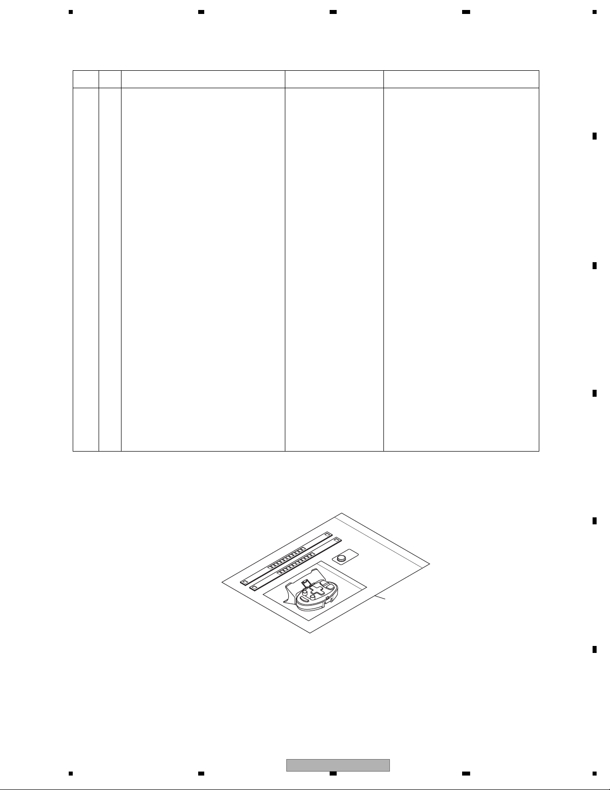
EXPLODED VIEWS AND PARTS LIST
PACKING(Page 6)
-
PACKING SECTION PARTS LIST
Mark No. Description AVIC-90DVD/UC AVIC-88DVD/UC
1-1 Owner’s Manual CRB1798 CRB1975
1-2 Owner’s Manual/PA/FRE CRB1783 CRB1977(Owner’s Manual/POC/FRE)
1-3 Owner’s Manual CRB1796 CRB1974
1-4 Owner’s Manual/PA/FRE CRB1797 CRB1976(Owner’s Manual/POC/FRE)
1-5 Installation Manual CRD3650 Not used
1-6 Owner’s Manual CRD3661 CRD3914(Installation Manual)
2 Cord Assy CDE7062 CDE7725
3 Accessory Assy CEA2913 CEA4467
8 Accessory Assy CEA2536 CEA4299(Connector Assy)
9 Polyethylene Bag CEG1011 * E36-615
10 Battery CEX1021 Not used
12 Sheet CNM6370 Not used
13 Holder CNS5606 Not used
17 Screw Assy CEA2896 CEA4465
19 Screw CMZ50P060FMC CMZ50P060FTC
* : Non spare part
A
B
23 Carton CHG4738 CHG5266
25 Contain Box CHL4738 CHL5266
31 Remote Control Assy CXB9118 Not used
34 DVD-ROM CPJ1143 CPJ1161
35 Screw Assy CEA2938 CEA4466
36 Screw(M6x16) CBA1295 CBA1795
* 37 Polyethylene Bag E36-613 CNM4338(Polyethylene Sheet)
38 Remote Control Assy Not used CXC3646
38
C
D
E
56
AVIC-88DVD/UC
F
7
8
3
1234
EXTERIOR(Page 12)
-
EXTERIOR SECTION PARTS LIST
Mark No. Description AVIC-90DVD/UC AVIC-88DVD/UC
A
1 Screw BMZ20P025FMC BMZ20P025FTC
2 Screw BMZ26P040FMC BMZ26P040FTC
23 CC Unit CWM8391 CWM9059
36 Screw IMS26P030FMC IMS26P030FTC
37 Main Unit CWM8484 CWM9642
73 GPS Unit CWX2591 CWX2925
79 Screw BPZ20P050FMC BPZ20P050FTC
B
83 Grille Assy CXB9890 CXC3631(Grille Unit)
90 Door Unit CXB7566 CXC3674
91 DVD Mechanism Module(MS2) CXK6160 CXK6121
96 Cord Assy CDE7062 CDE7725
103 Grille Unit GXX1229 GXX1246
104 Door Unit GXX1223 GXX1247
C
D
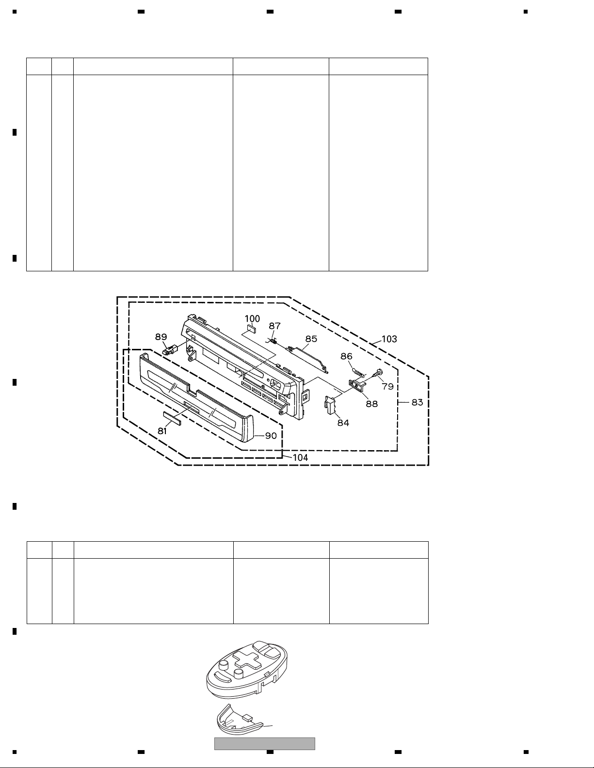
REMOTE CONTROL ASSY(Page 16)
-
REMOTE CONTROL ASSY SECTION PARTS LIST
Mark No. Description AVIC-90DVD/UC AVIC-88DVD/UC
E
1 Remote Control Assy CXB9118 Not used
2 Cover CZN5432 Not used
3 Scroll Stick CZA5047 Not used
4 3D View Stick CZA5085 Not used
5 Cover Not used CZN5497
F
5
4
1234
AVIC-88DVD/UC
5678
ELECTRICAL PARTS LIST(Page 110)
MAIN UNIT
Circuit Symbol and No. AVIC-90DVD/UC AVIC-88DVD/UC
IC571 IC S-81250SGUP S-812C50AUA-C3E
IC631 IC S-8423AFS S-8424AABFT
D1841 Diode MA110 MA111
FU1801 Fuse 2A CEK1190 CEK1257
FU1802, 1804 Fuse 4A CEK1199 CEK1260
FU1850, 3251 Fuse 1A CEK1191 CEK1254
GY572 Sensor CSX1052 CSX1050
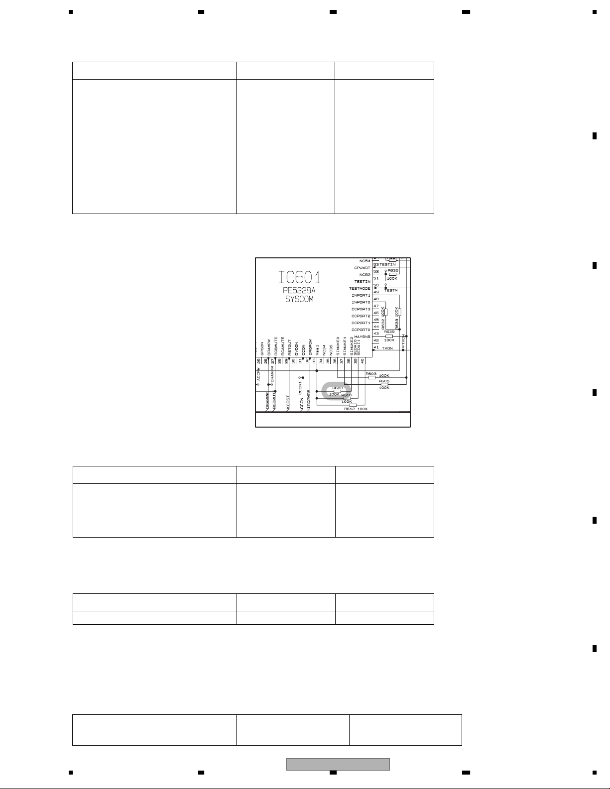
R607 RS1/16S104J Not used
R608 Not used RS1/16S104J
Page 31 7-B
A
B
C
CC UNIT
Circuit Symbol and No. AVIC-90DVD/UC AVIC-88DVD/UC
IC110 IC PD6403B PD6444B
IC111 IC PD6404B PD6445B
FU801 Fuse 4A CEK1199 CEK1260
FU802, 803 Fuse 2.5A CEK1209 CEK1258
GPS UNIT
Circuit Symbol and No. AVIC-90DVD/UC AVIC-88DVD/UC
IC502 IC PD6362B PD6452A
ADJUSTMENT
USING THE TEST DISC(Page 166)
AVIC-90DVD/UC AVIC-88DVD/UC
TEST DISC GGV1059(CNDK-LT0102) GGV1132(S-57364)
D
E
F
56
AVIC-88DVD/UC
7
8
5
N
1234
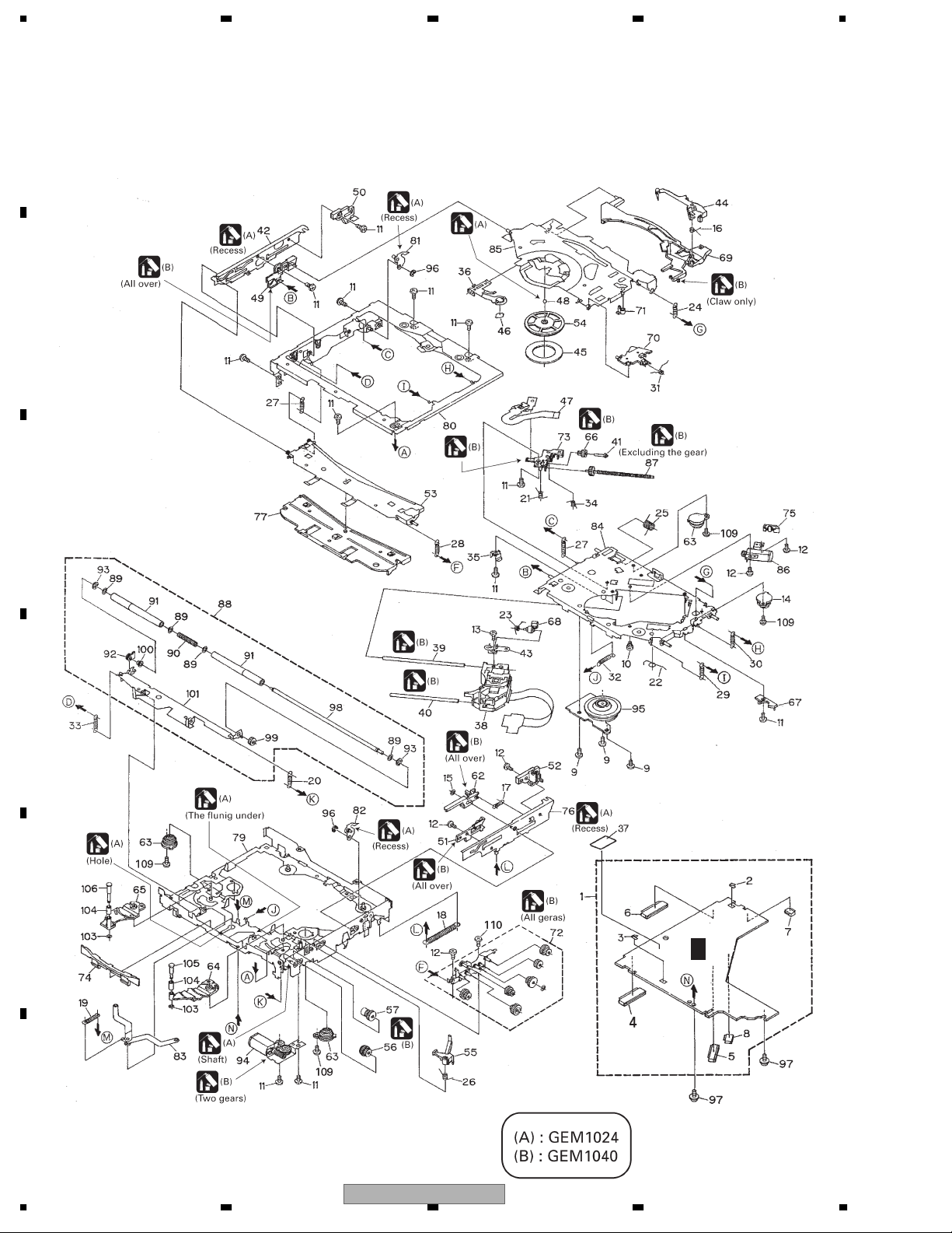
EXPLODED VIEWS AND PARTS LIST
OTES : • Parts marked by " * " are generally unavailable because they are not in our Master Spare Parts List.
A
• Screw adjacent to mark on the product are used for disassembly.
• For the applying amount of lobricants or glue, follow the instructions in this manual.
(In the case of no amount instructions,apply as you think it appropriate.)
"
DVD MECHANISM MODULE
B
C
D
E
F
G
F
6
1234
AVIC-88DVD/UC

5678
DVD MECHANISM MODULE SECTION PARTS LIST
Mark No. Description Part No.
1 DVD Core Unit R CWX2576
2 Terminal(CN1703) CKF1065
3 Terminal(CN1705) CKF1065
4 Connector(CN1401) CKS4052
5 Connector(CN1100) CKS3749
6 Connector(CN1701) CKS4052
7 Connector(CN1700) CKS4374
8 Connector(CN1300) CKS4507
9 Screw(M2x3) CBA1486
10 Screw CBA1535
11 Screw(M2x2.2) CBA1547
12 Screw(M2x2.2) CBA1548
13 Screw(M1.4x2) CBA1549
14 Damper CNV6927
15 Washer CBF1038
16 Spring CBH2394
17 Spring CBH2395
18 Spring CBH2396
19 Spring CBH2397
20 Spring CBH2622
21 Spring CBH2399
22 Spring CBH2400
23 Spring CBH2401
24 Spring CBH2402
25 Spring CBH2403
26 Spring CBH2404
27 Spring CBH2405
28 Spring CBH2406
29 Spring CBH2407
30 Spring CBH2408
31 Spring CBH2410
32 Spring CBH2411
33 Spring CBH2413
34 Spring CBH2414
35 Spring CBL1499
36 Spring CBL1500
37 Sheet CNM7590
38 Pickup Unit(DP4)(Service) CXX1530
39 Shaft CLA3878
40 Shaft CLA3879
41 Shaft CLA3881
42 Lever CNC8988
43 Bracket CNC8992
44 Arm CNC8994
45 Sheet CNM8149
46 Sheet CNM6884
47 PCB CNP5971
48 Ball CNR1189
49 Guide CNV6352
50 Guide CNV6353
51 Guide CNV6354
52 Guide CNV6355
53 Guide CNV6356
54 Clamper CNV6357
No. Description Part No.
Mark
55 Arm CNV6358
56 Gear CNV6361
57 Gear CNV6362
58-61 •••••
62 Rack CNV6367
63 Damper CNV6368
64 Arm CNV6369
65 Arm CNV6370
66 Gear CNV6372
67 Holder CNV6374
68 Rack CNV6376
69 Arm CNV6377
70 Arm CNV6378
71 Arm CNV6379
72 Gear Unit CXB5959
73 Holder CNV6383
74 Guide CNV6384
75 Holder CNV6385
76 Lever Unit CXB5943
77 Holder Unit CXB5944
78 •••••
79 Frame Unit CXB5948
80 Frame Unit CXB5949
81 Arm Unit CXB5950
82 Arm Unit CXB5951
83 Arm Unit CXB5952
84 Chassis Unit CXB5953
85 Arm Unit CXB5954
86 Motor Unit(CRG)(M2) CXC4218
87 Screw Unit CXB5957
88 Roller Unit CXB5958
89 Washer CBF1060
90 Spring CBH2170
91 Roller CNV6068
92 Holder CNV6210
93 Washer YE20FTC
94 Motor Unit(LOAD)(M1) CXC1187
95 Motor Unit(SPDL)(M3) CXB6218
96 Washer YE15FTC
97 Screw IMS20P030FTC
* 98 Shaft CLA3877
* 99 Gear CNV6359
* 100 Caller CNV6382
* 101 Arm Unit CXB5945
102 •••••
103 Washer CBF1087
104 Roller CNV6928
105 Shaft CLA4180
106 Shaft CLA4181
107,108•••••
109 Screw (M2x3.5) CBA1560
110 Screw (M2x2.2) CBA1419
A
B
C
D
E
F
56
AVIC-88DVD/UC
7
8
7
1234
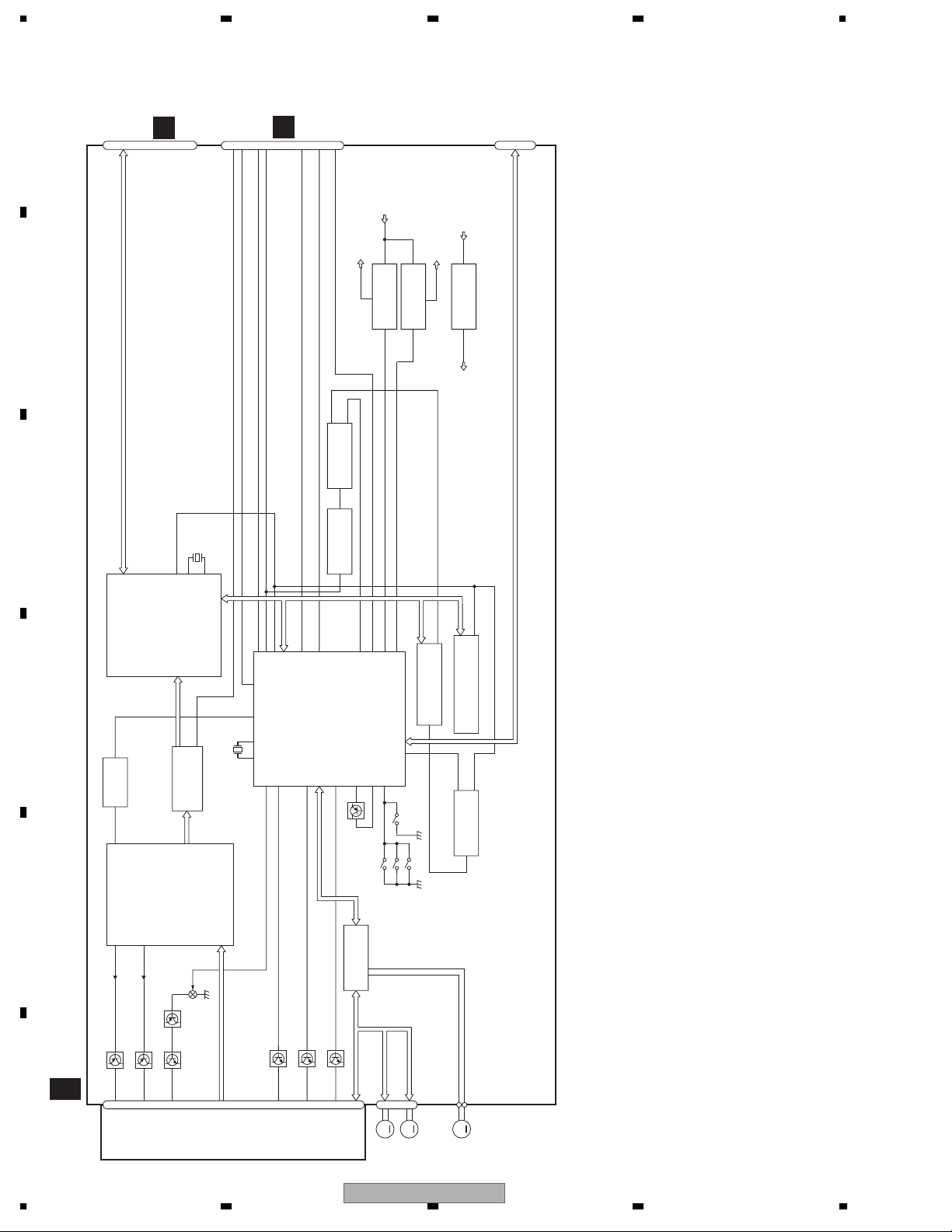
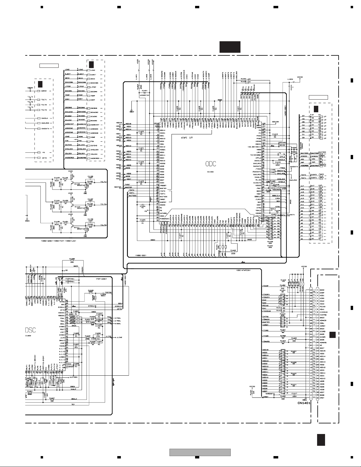
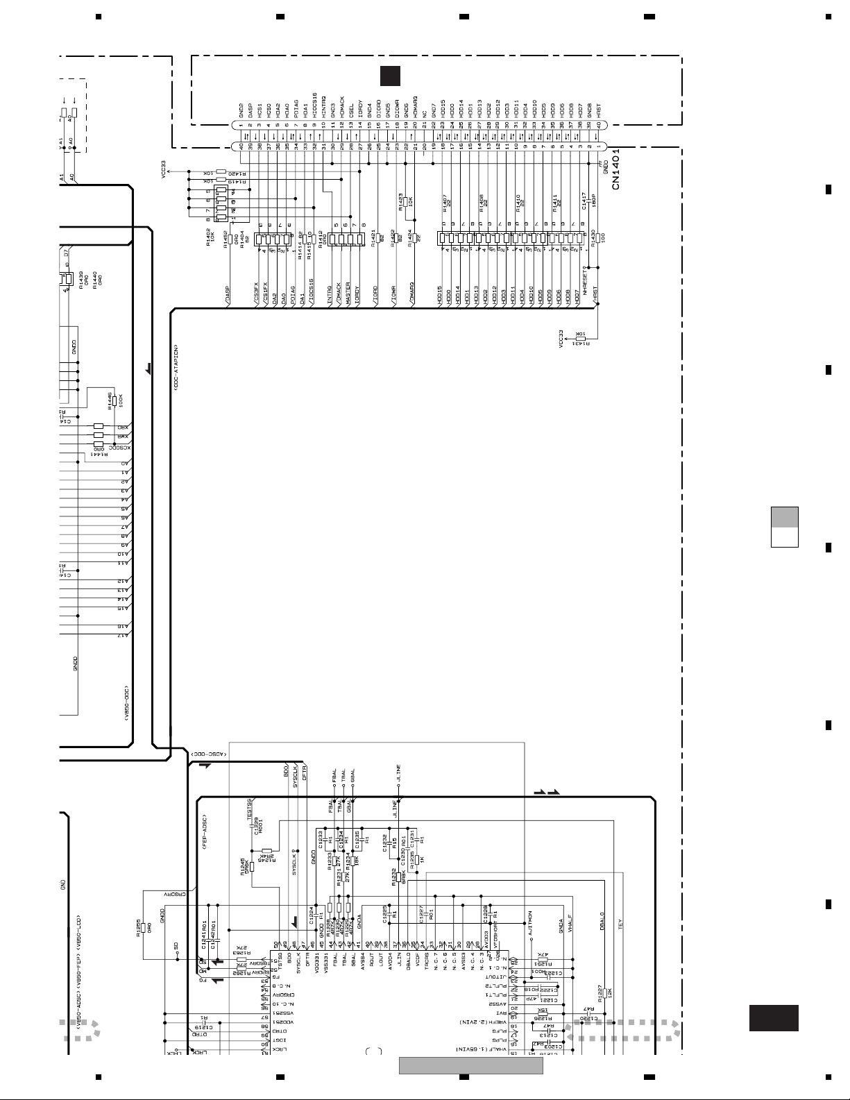
BLOCK DIAGRAM AND SCHEMATIC DIAGRAM
BLOCK DIAGRAM
EMPH
33
XRESET
16
CN3251
A
22
20
AMUTE
TMODE
21
EJSNS
CN1700
VD5
A
CN1401
E
37
AOUT0
CN1701
26
DISCDET
CN2
VCC27
2
4
B
4
IC 1804
BA00BC0WFP
1
1
2
IC 1802
BA033SFP
1
VCC33
4
4
IC 1801
BA05SFP
2
VD63 VCC5
CTS,DTR,RXPC,TXPC,VPP,SICOMN,SOCOMN,SCKCOMN
IC 1705
TC7SH32FU
C
X1500
33MHz
59
100
101
XWR
ODC
IC 1400
MNZS25BDAUB
D
97
59
114
XWR
EMPH
XRESET
DISCDET
X2ENV
66
5MHz
X1700
X2 X1
62 63 78 105
TILT1
ADSC
IC 1101
NJM2904M
57
IC 1200
MN677061ZYUB
FBAL
TBAL,
GBAL,
94
CD/DVD
23
A0-17,D0-15
25
TMODE
CPU
IC 1700
TILT2
36
IC 1703
TC7SH04FU
243
88
AMUTE
PE5324C
TILT3
33
718379
Q1700
74
107
XCSSRAM
AVRE F
EJSNS
ADENA
116
VCONTA
DSCSNS
117
VCONTB
XUWR
S1301
6
SRAM
IC 1701
M5M5V216ATP-70HI
17
96
CLAMP SW
FLASH MEMORY
2
11
IC 1702
PD6378D
1
IC 1704
TC7SH08FU
4
FEP
IC 1100
4
AN8702FH
LPC02
Q1107
Q1105
E
LPC01 RFENV
241
12cm detect SW
10
IC 1300
BA5985FM
DRIVER BLOCK
9
S1303
S1304
8cm detect SW
LOP
LOM
S1302
L/E ON/OFF SW
DVD CORE UNIT R
Q1109
Q1110
Q1104
Q1108
F
G
65LD
CN1100
F
8
Q1102
27
PICKUP
UNIT
A,B1-4,C,RF+,RF-
(DP4)
(SERVICE)
LCDSG1
78LD
30
VSHF
28
1234
Q1111
LCDSG2
6
LCDSG3
7
EC,CONT
FOP,FOM,TOP,TOM
CN1300
8
M
MOTOR
SPINDLE
AVIC-88DVD/UC
COP,COM
M
MOTOR
CARRIAGE
M
MOTOR
LOADING

5678
A
B
C
D
E
56
AVIC-88DVD/UC
F
7
8
9
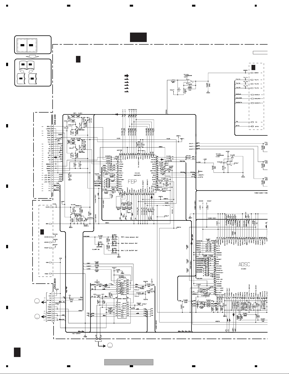
1234
DVD MECHANISM MODULE(1/2)(GUIDE PAGE)
Note: When ordering service parts, be sure to refer to " EXPLODED VIEWS AND PARTS LIST" or
"ELECTRICAL PARTS LIST".
A
Large size
A-b
A-b
SCH diagram
Guide page
Detailed page
G
DVD CORE UNIT R(FRONT END)
F
1/2
A-a A-b
A-a
A-a
B
GF-a
RF SIGNAL
F
FOCUS SERVO LINE
T
TRACKING SERVO LINE
C
CARRIAGE SERVO LINE
S
SPINDLE SERVO LINE
CLK
CLOCK LINE
1/2
SERVO-CPU I/F
G
F
2/2
RF AMP BLOCK
2.2V
C
1.65V
PICKUP UNIT(DP4)(SERVICE)
T
F
5.0V
POWER SUPPLY
T
2
5.0V
3.3V
8
2.2V
1.65V
F
3
0
SERVO CONTROLLER BLOCK
D
S
G
F
2/2
8.0V
DISC DETECT SWITCH
T
F
POWER SUPPLY
3.3V
2.7V
MN677061ZYUB
E
F
T
M2
M
SPINDLE
MOTOR
CXC4218
M3
M
CARRIAGE
MOTOR
CXB5955
S
C
S
F
G
F
1/2
10
1234
9
C
S
S
T
C
POWER SUPPLY
8.0V
C
DRIVER BLOCK
M1
M
LOADING
MOTOR
CXC1187
F
AVIC-88DVD/UC
4
F
T
7
6
T
F
1
F
T
S
T
T
C
F
F
7
5678
A
GF-b
1/2
SERVO-CPU I/F
G
F
2/2
G
F
2/2
OPTICAL DISC CONTROLLER BLOCK
ODC-CPU I/F
G
F
2/2
B
5
POWER SUPPLY
3.3V
2.7V
MNZS25BDAUB
I/F
SYSTEM
CONTROLLER
SYSTEM CONTROLLER I/F
CLK
CLK
C
R1442 220
R1443 220
ROLLER BLOCK
WER SUPPLY
3.3V
2.7V
CLK
C
S
CLK
CLK
ATAPI I/F
D
1/6 CN2
7061ZYUB
E
E
C
S
56
AVIC-88DVD/UC
F
G
F
1/2
7
8
11

SERVO CONTROLLER BLOCK
1234
A
B
C
GF-b
1/2
SERVO-CPU I/F
2/2
F
G
1
1.65V
3
2.2V
0
2
1.65V
2.2V
8
GF-b
A-a
GF-a
RF SIGNAL
FOCUS SERVO LINE
TRACKING SERVO LINE
CARRIAGE SERVO LINE
SPINDLE SERVO LINE
C
S
CLOCK LINE
CLK
RF AMP BLOCK
5.0V
3.3V
POWER SUPPLY
D
T
F
DVD CORE UNIT R(FRONT END)
E
1/2
F
G
F
T
5.0V
F
GF-a
12
PICKUP UNIT(DP4)(SERVICE)
1/2
AVIC-88DVD/UC
1234

P
5678
C
S
A
8
2.2V
SERVO CONTROLLER BLOCK
F
T
1.65V
3.3V
2.7V
POWER SUPPLY
MN677061ZYUB
6
3
GF-b
1/2
T
F
F
T
1
C
S
T
T
F
F
B
C
4
7
GF-b
F
T
F
F
T
A-a
GF-a
D
2
T
8.0V
POWER SUPPLY
DRIVER BLOCK
M1
M
MOTOR
CXC1187
C
DISC DETECT SWITCH
F
5.0V
8.0V
9
S
S
T
F
S
C
C
S
C
LOADING
E
2/2
F
G
M3
M2
M
MOTOR
SPINDLE
56
AVIC-88DVD/UC
CXC4218
7
M
MOTOR
CXB5955
CARRIAGE
GF-a
8
1/2
F
13

1234
A
ODC-CPU I/F
B
C
GF-b
GF-a
OPTICAL DISC CONTROLLER BLOCK
2/2
F
G
CLK
CLK
CLK
R1443 220
R1442 220
3.3V
2.7V
POWER SUPPLY
MNZS25BDAUB
SYSTEM CONTROLLER I/F
I/F
CONTROLLER
SYSTEM
D
E
2/2
F
G
5
F
GF-b
1/2
14
2/2
SERVO-CPU I/F
F
G
1
2
AVIC-88DVD/UC
1234
5678
1/6 CN2
E
A
B
ATAPI I/F
CLK
R1443 220
R1442 220
C
GF-b
GF-a
D
CLK
C
S
E
CLK
C
S
ER BLOCK
PLY
YUB
AVIC-88DVD/UC
56
F
3
GF-b
1/2
7
8
15

1234
DVD MECHANISM MODULE(2/2)
A
B
4/5 CN3251
A
1/2
F
G
C
PD6378D
1/2
F
3.3V
G
SERVO-CPU I/F
1/2
F
G
1/2
F
G
2.7V
D
POWER SUPPLY
E
1/2
6.3V(5.0V)
F
G
DVD CORE UNIT R(BACK END)
2/2
F
G
F
16
F
G
2/2
1234
1/2
F
G
AVIC-88DVD/UC
3.3V

5678
A
B
PE5324C
POWER SUPPLY 3.3V
CLOCK FREQUENCY 5MHz
C
D
MICRO COMPUTER BLOCK
E
3.3V
56
AVIC-88DVD/UC
F
G
F
2/2
7
8
17
1234
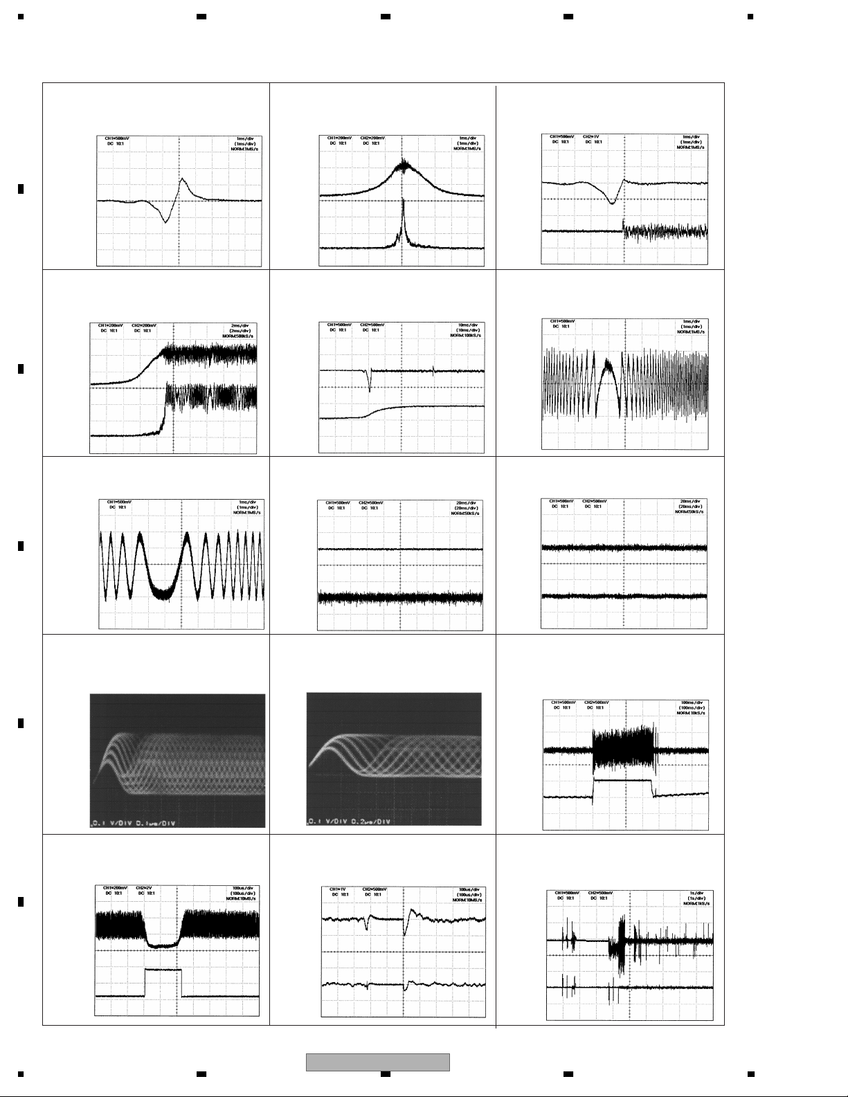
- Waveforms
1 FEY 500mV/div. 1ms/div.
A
B
C
Focus search
VHALF→
2 CH1: ASF
3 CH1: RFENV
200mV/div. 2ms/div.
Focus close
VHALF→
VHALF→
6 CH1: TEY 500mV/div. 1ms/div.
Focus close(CD)
Note:1. The encircled number denote measuring pointes in the circuit diagram.
2.
Reference voltage VHALF : 1.65V
2 CH1: ASF
3 CH2: RFENV
Focus search
VHALF→
VHALF→
1 CH1: FEY
5 CH2: FOK
200ms/div. 1ms/div.
500mV/div. 10ms/div.
1 CH1: FEY 500mV/div. 1ms/div.
4 CH2: FD 1V/div. 1ms/div.
Focus close
VHALF→
VHALF→
6 CH1: TEY 500mV/div. 1ms/div.
Focus close(DVD)
Focus close
VHALF→
VHALF→
1 CH1: FEY
4 CH2: FD
Play
500mV/div.20ms/div.
VHALF→
6 CH1: TEY
7 CH2: TD
Play
500mV/div.20ms/div.
VHALF→
D
8 CH1: RFOUT 0.1V/div. 0.1µs/div.
Play(DVD surroundings on inside)
E
8 CH1: RFOUT 200mV/div. 100µs/div.
0 CH2: BDO 2V/div. 100µs/div.
Black dot
VHALF→
VHALF→
VHALF→
8 CH1: RFOUT 0.1V/div. 0.2µs/div.
Play(CD)
4 CH1: FD 1V/div. 100µs/div.
7 CH2: TD 500mV/div. 100µs/div.
Black dot
VHALF→
VHALF→
VHALF→
6 CH1: TEY
500mV/di v. 100ms/div .
9 CH2: CRGDRV
Surroundings on inside->
surroundings on outside
VHALF→
VHALF→
6 CH1: TEY
1 CH2: FEY
500mV/div.1s/div.
EDC1 mode set up(DVD)
VHALF→
VHALF→
F
18
1234
VHALF→
VHALF→
AVIC-88DVD/UC

5678
PU UNIT(REFERENCE)
A
SHORT
LAND
F1/2
G
CN1100
B
C
D
56
AVIC-88DVD/UC
E
F
7
8
19
1234
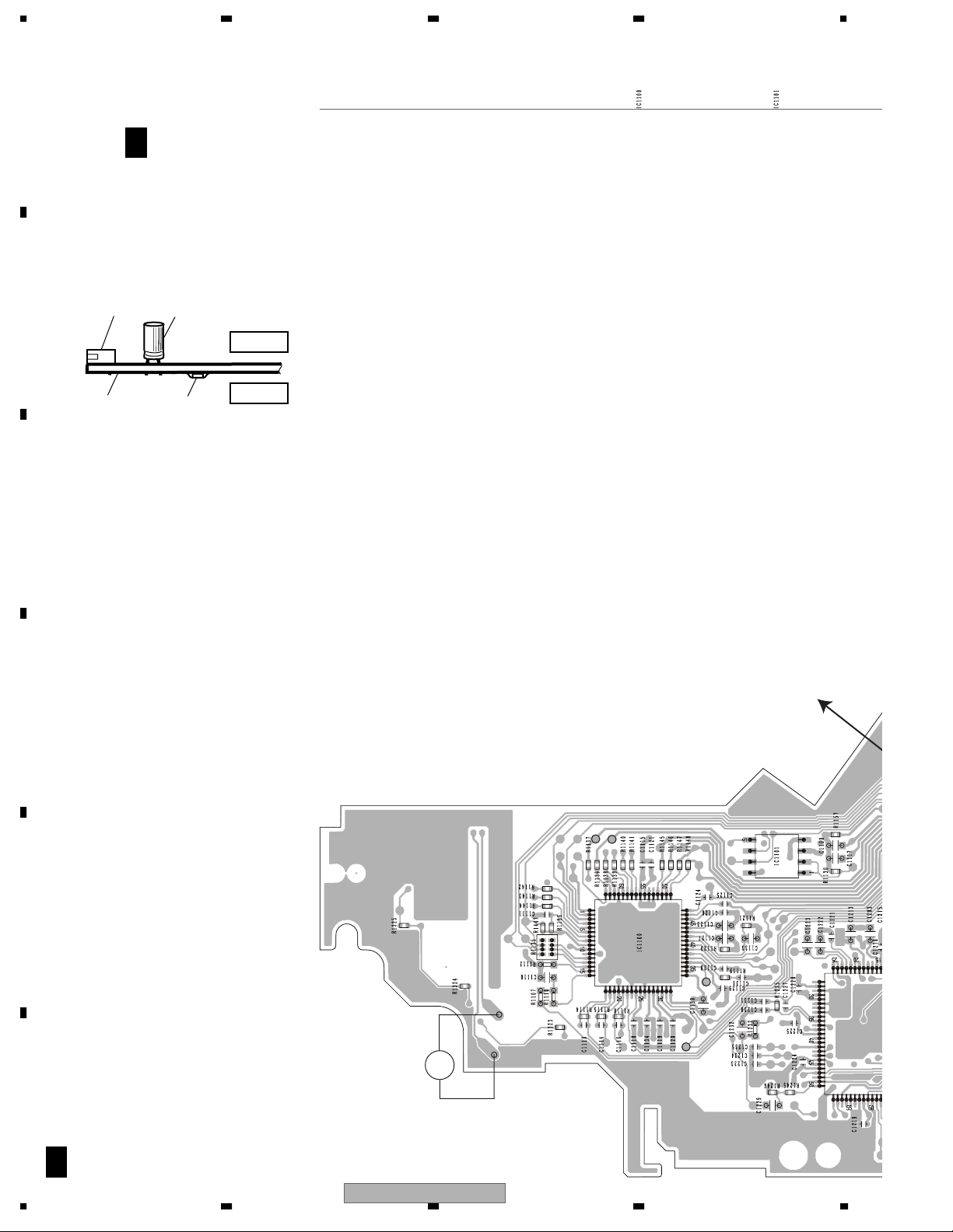
PCB CONNECTION DIAGRAM
DVD CORE UNIT R
A
DVD CORE UNIT R
F
G
NOTE FOR PCB DIAGRAMS
1.The parts mounted on this PCB
include all necessary parts for
several destination.
For further information for
respective destinations, be sure
to check with the schematic dia gram.
2.Viewpoint of PCB diagrams
B
C
Connector
P.C.Board
Capacitor
Chip Part
SIDE A
SIDE B
IC,Q
D
A
C
E
RFOUT
M1
F
VHALF1
(DP4)
(SERVICE)
PICKUP UNIT
20
G
F
AVIC-88DVD/UC
1234

5678
M3
GND1
SIDE A
A
CN3251
A
B
C
(SERVICE)
M2
D
VREF1
E
56
AVIC-88DVD/UC
CN2
E
F
F
G
7
8
21

1234
DVD CORE UNIT R
F
A
B
G
C
D
E
L/E ON/OFF
F
F
G
22
1234
AVIC-88DVD/UC

5678
IC,Q
SIDE B
A
B
C
12cm DETECT
8cm DETECT
D
CLAMP
E
F
56
AVIC-88DVD/UC
F
G
7
8
23

1234
ELECTRICAL PARTS LIST
NOTE:
A
• Parts whose parts numbers are omitted are subject to being not supplied.
• The part numbers shown below indicate chip components.
Chip Resistor
RS1/_S___J,RS1/__S___J
Chip Capacitor (except for CQS.....)
CKS....., CCS....., CSZS.....
Circuit Symbol and No. Part No.
B
F
G
Unit Number:CWX2576
Unit Name:DVD Core Unit R
MISCELLANEOUS
IC 1100 IC AN8702FH
IC 1101 IC NJM2904M
IC 1200 IC MN677061ZYUB
IC 1300 IC BA5985FM
IC 1400 IC MNZS25BDAUB
C
IC 1700 IC PE5324C
IC 1701 IC M5M5V216ATP-70HI
IC 1702 IC PD6378D
IC 1703 IC TC7SH04FU
IC 1704 IC TC7SH08FU
IC 1705 IC TC7SH32FU
IC 1801 IC BA05SFP
IC 1802 IC BA033SFP
IC 1804 IC BA00BC0WFP
Q 1102 Transistor 2SD601A
D
Q 1104 Transistor 2SB1260
Q 1105 Transistor 2SB709A
Q 1107 Transistor UN2211
Q 1108 Transistor 2SB1260
Q 1109 Chip T r ansistor 2SC2712
Q 1110 Chip T r ansistor 2SC2712
Q 1111 Chip T r ansistor 2SC2712
Q 1700 Transistor DTA123JK
D 1100 Diode 1SS355
D 1101 Diode 1SS355
D 1401 Diode UDZ2R7(B)
E
D 1800 Diode S2G-6600
D 1801 Diode S2G-6600
D 1802 Diode S2G-6600
D 1803 Diode S2G-6600
L 1201 Inductor CTF1295
L 1202 Inductor CTF1295
L 1401 Inductor CTF1399
L 1402 Inductor CTF1399
L 1403 Inductor CTF1395
L 1404 Inductor CTF1410
L 1406 Inductor CTF1410
F
L 1407 Inductor CTF1410
L 1700 Inductor CTF1395
L 1701 Inductor CTF1399
24
1234
Circuit Symbol and No. Part No.
L 1702 Inductor CTF1473
L 1704 Inductor CTF1410
L 1705 Inductor CTF1470
L 1706 Inductor CTF1470
L 1707 Inductor CTF1470
L 1708 Inductor CTF1470
L 1709 Inductor CTF1470
L 1710 Inductor CTF1470
L 1711 Inductor CTF1470
L 1712 Inductor CTF1470
L 1713 Inductor CTF1470
L 1714 Inductor CTF1470
L 1715 Inductor CTF1470
L 1720 Inductor CTF1410
X 1500 Radiator 33.8688MHz CSS1548
X 1700 Ceramic Resonator 4.97MHz CSS1547
S 1301 Spring Switch(CLAMP) CSN1051
S 1302 Spring Switch(L/E ON/OFF) CSN1051
S 1303 Spring Switch(8cm DETECT) CSN1051
S 1304 Spring Switch(12cm DETECT)CSN1051
RESISTORS
R 1102 RS1/16SS3R9J
R 1104 RS1/16SS3R9J
R 1105 RS1/16SS122J
R 1106 RS1/16SS472J
R 1107 RS1/16S6201D
R 1108 RS1/16SS3R9J
R 1109 RS1/16SS3R9J
R 1110 RS1/16S1002D
R 1113 RS1/16S2402D
R 1114 RS1/16SS823J
R 1115 RS1/16SS682J
R 1116 RS1/16SS3R9J
R 1117 RS1/16SS3R9J
R 1118 RS1/16SS223J
R 1119 RS1/16SS202J
R 1120 RS1/16SS105J
R 1121 RS1/16SS105J
R 1122 RS1/16SS103J
R 1123 RS1/16SS103J
R 1124 RS1/16SS103J
R 1125 RS1/16SS103J
R 1126 RS1/16SS103J
R 1127 RS1/16SS103J
R 1128 RS1/16SS3R9J
R 1129 RS1/16SS3R9J
R 1130 RS1/16SS102J
R 1131 RS1/16SS102J
AVIC-88DVD/UC

5678
Circuit Symbol and No. Part No.
R 1132 RS1/16SS102J
R 1133 RS1/16SS102J
R 1134 RS1/16SS102J
R 1135 RAB4CQ0R0J
R 1136 RS1/16SS133J
R 1137 RS1/16SS133J
R 1138 RS1/16SS0R0J
R 1139 RS1/16SS0R0J
Circuit Symbol and No. Part No.
R 1255 RS1/16SS0R0J
R 1257 RS1/16S221J
R 1258 RAB4CQ221J
R 1262 RS1/16SS273J
R 1263 RS1/16SS273J
R 1264 RS1/16SS104J
R 1301 RS1/16S3902D
R 1302 RS1/16S3902D
A
R 1140 RS1/16SS0R0J
R 1141 RS1/16SS0R0J
R 1142 RS1/16SS183J
R 1143 RS1/16SS273J
R 1144 RS1/16SS273J
R 1145 RS1/16SS0R0J
R 1146 RS1/16SS0R0J
R 1147 RS1/16SS0R0J
R 1148 RS1/16SS0R0J
R 1149 RS1/16SS102J
R 1150 RS1/16SS102J
R 1151 RS1/16SS102J
R 1152 RS1/16SS154J
R 1153 RS1/16SS154J
R 1154 RS1/16SS154J
R 1156 RS1/16SS224J
R 1157 RS1/16SS0R0J
R 1158 RS1/16SS330J
R 1159 RS1/16SS330J
R 1201 RS1/16SS203J
R 1202 RS1/16SS102J
R 1203 RS1/16SS471J
R 1204 RS1/16S0R0J
R 1205 RS1/16SS222J
R 1206 RS1/16SS473J
R 1303 RS1/16S3002D
R 1304 RS1/16S3902D
R 1305 RS1/16SS221J
R 1306 RS1/16SS0R0J
R 1307 RS1/16SS221J
R 1308 RS1/16S3002D
R 1310 RS1/16SS102J
R 1311 RS1/16S3902D
R 1312 RS1/16S0R0J
R 1314 RS1/16SS221J
R 1321 RS1/16SS221J
R 1323 RS1/16SS104J
R 1324 RS1/16SS473J
R 1325 RS1/16SS273J
R 1402 RAB4CQ103J
R 1403 RS1/16SS222J
R 1404 RAB4CQ820J
R 1407 RAB4CQ220J
R 1408 RAB4CQ220J
R 1410 RAB4CQ220J
R 1411 RAB4CQ220J
R 1412 RAB4CQ0R0J
R 1414 RS1/16SS820J
R 1415 RS1/16SS100J
R 1419 RS1/16SS103J
B
C
R 1207 RS1/16SS101J
R 1208 RS1/16SS101J
R 1209 RS1/16SS473J
R 1212 RS1/16SS473J
R 1213 RS1/16SS101J
R 1215 RS1/16SS123J
R 1216 RS1/16SS473J
R 1219 RS1/16SS123J
R 1220 RS1/16SS105J
R 1221 RS1/16SS562J
R 1222 RS1/16SS273J
R 1223 RS1/16SS273J
R 1226 RS1/16SS153J
R 1227 RS1/16SS123J
R 1228 RS1/16SS472J
R 1229 RS1/16SS472J
R 1230 RS1/16SS472J
R 1231 RS1/16SS273J
R 1232 RS1/16S6801D
R 1233 RS1/16SS273J
R 1234 RS1/16SS183J
R 1235 RS1/16SS102J
R 1242 RAB4CQ221J
R 1243 RAB4CQ221J
R 1245 RS1/16SS562J
R 1420 RS1/16SS103J
R 1421 RS1/16SS820J
R 1422 RS1/16SS820J
R 1423 RS1/16SS103J
R 1424 RS1/16SS220J
R 1429 RS1/16S470J
R 1430 RS1/16SS101J
R 1431 RS1/16SS103J
R 1436 RS1/16SS103J
R 1437 RS1/16SS103J
R 1438 RS1/16SS221J
R 1439 RAB4CQ0R0J
R 1440 RAB4CQ0R0J
R 1441 RS1/16SS0R0J
R 1442 RS1/16SS221J
R 1443 RS1/16SS221J
R 1446 RS1/16SS104J
R 1447 RS1/16SS104J
R 1451 RS1/16S0R0J
R 1452 RS1/16SS0R0J
R 1501 RS1/16SS105J
R 1701 RN1/16SE1502D
R 1702 RS1/16SS0R0J
R 1703 RS1/16SS221J
R 1704 RS1/16SS104J
D
E
F
R 1246 RS1/16SS242J
R 1251 RS1/16SS473J
56
R 1705 RS1/16SS103J
R 1706 RS1/16SS103J
AVIC-88DVD/UC
7
8
25

1234
Circuit Symbol and No. Part No.
R 1707 RS1/16SS104J
R 1708 RS1/16SS0R0J
R 1709 RS1/16SS104J
A
R 1710 RS1/16SS473J
R 1711 RS1/16SS221J
R 1712 RS1/16SS104J
R 1713 RS1/16SS104J
R 1714 RS1/16SS104J
R 1715 RS1/16SS472J
R 1716 RS1/16SS104J
R 1717 RS1/16SS473J
R 1718 RS1/16SS104J
R 1719 RS1/16SS104J
B
R 1720 RS1/16SS473J
R 1721 RS1/16SS104J
R 1722 RS1/16SS104J
R 1723 RS1/16SS473J
R 1724 RS1/16SS221J
R 1726 RS1/16SS104J
R 1727 RS1/16SS103J
R 1728 RS1/16SS104J
R 1729 RS1/16SS104J
R 1730 RS1/16SS473J
R 1731 RS1/16SS221J
C
R 1732 RS1/16SS221J
R 1733 RS1/16SS104J
R 1734 RS1/16SS104J
R 1735 RS1/16SS222J
R 1736 RS1/16SS221J
R 1737 RS1/16SS221J
R 1738 RS1/16SS104J
R 1739 RS1/16SS103J
R 1740 RS1/16SS103J
R 1742 RS1/16SS104J
R 1747 RS1/16SS222J
D
R 1748 RS1/16SS473J
R 1749 RS1/16SS104J
R 1750 RS1/16SS472J
R 1751 RS1/16SS103J
R 1752 RS1/16SS104J
R 1756 RS1/16SS473J
R 1757 RS1/16SS472J
R 1762 RS1/16SS104J
R 1763 RS1/16SS104J
R 1764 RS1/16SS104J
R 1766 RS1/16SS104J
E
R 1771 RS1/16SS104J
R 1772 RS1/16SS104J
R 1773 RS1/16SS104J
R 1774 RS1/16SS473J
R 1775 RS1/16SS221J
R 1776 RS1/16SS104J
R 1777 RS1/16SS104J
R 1801 RS1/16S3902D
R 1802 RS1/16S3302D
R 1808 RS1/16SS102J
R 1809 RS1/16SS102J
F
R 1810 RS1/16S0R0J
CAPACITORS
26
1234
AVIC-88DVD/UC
Circuit Symbol and No. Part No.
C 1100 CKSR YB105K10
C 1101 CKSR YB473K25
C 1102 CKSSYB103K16
C 1103 CSZSR101M6R3
C 1104 CKSSYB104K10
C 1105 CKSSYB104K10
C 1106 CKSR YB473K25
C 1107 CKSSYB103K16
C 1108 CSZSR101M6R3
C 1109 CKSSYB104K10
C 1110 CKSR YB154K10
C 1111 CCSSCH221J25
C 1114 CCSSCH330J50
C 1115 CKSSYB104K10
C 1116 CCSSCH221J25
C 1117 CKSR YB105K10
C 1118 CKSSYB104K10
C 1119 CKSSYB104K10
C 1120 CKSSYB104K10
C 1121 CKSSYB104K10
C 1122 CSZSC470M16
C 1123 CKSR YB273K25
C 1124 CKSSYB104K10
C 1125 CKSSYB104K10
C 1126 CKSSYB473K10
C 1127 CCSRCH561J50
C 1128 CKSSYB104K10
C 1129 CKSSYB104K10
C 1130 CCSRCH102J50
C 1131 CCSSCH120J50
C 1133 CCSRCH561J50
C 1134 CKSSYB104K10
C 1136 CCSSCH101J50
C 1137 CCSSCH101J50
C 1138 CCSSCH101J50
C 1139 CKSSYB104K10
C 1140 CKSSYB103K16
C 1141 CKSSYB104K10
C 1142 CKSSYB104K10
C 1143 CKSSYB473K10
C 1144 CKSSYB473K10
C 1145 CKSSYB103K16
C 1146 CKSSYB473K10
C 1148 CKSSYB103K16
C 1201 CKSR YB105K10
C 1202 CCSSCH101J50
C 1203 CKSR YB474K10
C 1204 CCSRCH561J50
C 1205 CCSRCH331J50
C 1206 CKSR YB105K10
C 1207 CKSSYB104K10
C 1208 CCSRCH471J50
C 1209 CCSRCH391J50
C 1210 CKSR YB105K10
C 1211 CCSSCH101J50
C 1212 CKSSYB104K10
C 1213 CKSR YB474K10
C 1214 CCSRCH102J50
C 1215 CCSRCH102J50
C 1216 CKSSYB562K25

5678
Circuit Symbol and No. Part No.
Circuit Symbol and No. Part No.
C 1217 CCSRCH102J50
C 1218 CKSSYB104K10
C 1219 CKSSYB104K10
C 1220 CKSR YB474K10
C 1221 CCSSCH470J50
C 1222 CKSR YB183K25
C 1223 CCSRCH102J50
C 1224 CKSSYB104K10
C 1225 CKSSYB104K10
C 1227 CKSSYB103K16
C 1228 CKSSYB104K10
C 1229 CCSRCH102J50
C 1230 CKSSYB103K16
C 1231 CKSSYB104K10
C 1232 CKSR YB154K10
C 1233 CKSSYB104K10
C 1234 CKSSYB104K10
C 1235 CKSSYB104K10
C 1236 CKSSYB471K50
C 1241 CKSSYB103K16
C 1242 CKSSYB103K16
C 1243 CKSSYB104K10
C 1300 CKSSYB103K16
C 1301 CKSSYB103K16
C 1304 CKSR YB104K16
C 1305 CEV101M16
C 1308 CKSSYB104K10
C 1400 CKSSYB104K10
C 1401 CKSSYB104K10
C 1402 CKSSYB104K10
C 1711 CKSSYB104K10
C 1712 CKSSYB103K16
C 1714 CKSYB106K6R3
C 1715 CKSSYB104K10
C 1719 CKSSYB471K50
C 1720 CKSSYB103K16
C 1721 CKSSYB104K10
C 1722 CKSSYB103K16
C 1728 CKSSYB104K10
C 1729 CKSSYB104K10
C 1730 CKSSYB104K10
C 1753 CKSR YB104K16
C 1801 CKSR YB474K10
C 1802 CKSR YB474K10
C 1803 CKSR YB474K10
C 1804 22µF/6.3V CCH1300
C 1805 22µF/6.3V CCH1300
C 1808 CSZSC101M10
C 1810 CCSRCH102J50
C 1812 CSZSC101M10
Miscellaneous Parts List
Pickup Unit(DP4)(Service) CXX1530
M 1 Motor Unit(LOADING) CXC1187
M 2 Motor Unit(CARRIAGE) CXC4218
M 3 Motor Unit(SPINDLE) CXB6218
A
B
C
C 1403 CKSSYB104K10
C 1404 CKSSYB104K10
C 1405 CKSSYB104K10
C 1406 CKSSYB104K10
C 1407 CKSSYB104K10
C 1408 CKSSYB104K10
C 1409 CKSSYB104K10
C 1410 CKSSYB104K10
C 1411 CKSSYB104K10
C 1412 CKSSYB104K10
C 1413 CKSSYB104K10
C 1414 CKSR YB105K10
C 1415 CKSSYB104K10
C 1416 CKSSYB104K10
C 1417 CCSSCH181J25
C 1418 CKSSYB471K50
C 1419 CCSSCH221J25
C 1534 CCSSCH5R0C50
C 1537 CCSSCH5R0C50
C 1700 CKSSYB104K10
C 1701 CKSSYB104K10
C 1702 CKSSYB104K10
C 1703 CKSSYB104K10
C 1704 CKSSYB104K10
C 1705 CKSSYB104K10
D
E
C 1706 CKSSYB104K10
C 1707 CKSR YB105K10
C 1708 CKSSYB104K10
C 1709 CKSSYB104K10
C 1710 CKSSYB104K10
56
AVIC-88DVD/UC
F
7
8
27

1234
ADJUSTMENT
DVD ADJUSTMENT
Cautions for servicing
A
This product uses 5V and 3.3V as standard voltages.
The electrical potential that is the reference for signals,
is not GND, but VREF (approximately 2.2V) and VHALF
(approximately 1.65V).
During product adjustments, if the reference voltage is
mistakenly taken as GND, and a grounding contact is
made, not only would it be impossible to measure the
accurate electrical potential, but also the servo motor
would malfunction, resulting in the application of a
strong impact on the pick up. The following precautionary measures should be strictly adhered to, in order to
B
avoid such problems.
The reference voltage and GND should not be confused
when using the minus probe of a measurement device.
When an oscilloscope is being used special care should
be taken to make sure that the reference voltage is not
connected to the probe of ch1 (on the minus side),
while the probe of ch2 (on the minus side), is connected
to GND. Further, since the body frame of most measurement devices have the same electrical potential as
the minus side of the probe, the body frame of the measurement device should be set to floating ground.
C
If the reference voltage is connected to GND by mistake, turn the regulator OFF immediatel y, or turn the
power OFF.
• Remove the filters and wires used for measurements
only after the regulator has been turned OFF.
• After the power supply is turned on, regulator ON the
following adjustment and measurement are promptly
done.
• Whenever the product is in the test mode, the software
will not take any protective action. For this reason,
special care should be taken to make sure that no
mechanical or electrical shock could be applied to the
product when taking measurements in the test mode.
• Whenever the EJECT key is pressed to eject the disk,
no other keys, other than the EJECT key, should be
pressed until the disk eject action has been completed.
• Press the EJECT key only after the disk has stopped
completely.
• If the product hangs up turn the power OFF immediately.
• Laser didoes may be damaged, if the volume switch for
the laser power adjustment of the pick up unit, is turned.
• Test mode starting procedure
The test mode can be selected from the navigation
test mode.
Please use the " remote control unit of the product
accessory" after the test mode starts.
D
E
F
28
1234
AVIC-88DVD/UC

5678
- Front-End test mode flow chart
FE offset coefficient
TE offset coefficient
AS offset coefficient
ENV offset coefficient
TG offset coefficient
DBALt coefficient
FE MAX level
FE MIN level
AS MAX level
ENV MAX level
FE normalization feature
Spindle gain coefficient
TBAL Coefficient
GBAL Coefficient
TE normalization feature
FBAL Coefficient
Focus Gain Coefficient
Tracking Gain Coefficient
AS normalization adjustment feature
Test mode In
Start test mode
Note 1: At this stage select the media type. Various settings are carried out
according to the media selection made here.
Note 2: While measurements are being taken, only the operation, for which
Set source to DVD
the measurement is being taken, is allowed.
Note 3: Reproduction (play) speed is selectable from: DVD x 1CAV ↔ x 1CLV,
TEST
CD x 2CLV ↔x 1CLV
123
FE
test mode
0000 0000
1
Power On
EDC1
mode
2~5 EJECT
Disc T ype
EDC2
mode
Power off condition
Eject
(Note 1)
0FFF 00000FFF 0000
1X00 0000
81
Power Off CRG +
Focus close
adjustment
1FFF 0000
1A00 0000
1100 0000
0X00 0000
2
Focus Search
2
Focus Search
Stop
34
CRG — LD_ON
81234
Power Off CRG +
T.Bal and
other
Focus Jump
CRG —
adjustments
2FFF 0000
8134
3000 0000
Power Off CRG —
Tracking close
Layer L0:2000 0000
Layer L1:2100 0000
CRG +
Operation while key is being pushed.
2B00 0000 2C00 0000
Operation while key is being pushed.
Focus close condition 2
adjustment
3FFF 0000
4000 0000
4X00 0000
812 5 6 73, 4
Power Off
Error Rate
measurement
(Note 2)
Error Rate
Focus Gain Coefficient
Tracking Gain Coefficient
AS normalization adjustment feature
3B00 0000
Reproduction
speed switching
(Note 3)
DVD x CAV
orCD x 2CLV:
4X00 0000
DVD x 1CAV
orCD x 1CLV:
4X00 0000
Layer L0:4X00 0000
Layer L1:4X00 0000
*Please refer to the next page for the
method of specfying ID.
Operation while key is being pushed.Operation while key is being pushed.
3C00 0000
Focus Jump
ID Search Tracking
4A00 0000
1~4
ID
specification
ID display
5
ID
Search Start
2 : DVD, single-layer
3 : DVD, dual-layer
4 : CD
5 : CD-RW
Power on condition
5
6
CRG_HOME
F-close and F-search cannot be executed, unless LD-ON is set.
[If F-close isn't executed within 9 seconds after LD-ON,
it switches to LD-OFF automatically. And even if F-search is executed
within 9 seconds after LD-ON, it also switches to LD-OFF
.]
Focus close condition 1
Tracking close condition
T. Jump
+/—
Jump+:
3
4B00 0000
Track number
specification
Track
number
display
4
Open
The track number designation is selected
from the track numbers already prepared
for selection.
Switching to cyclic operation is made at step
4, 3, and the decision is finalized (entered)
in step For CD: Tracks 1, 4, 10, 11 and 32.
For DVD: Tracks 1, 4, 10, 11, 32, 64 and 100.
Jump start
A
B
C
D
E
56
AVIC-88DVD/UC
F
7
8
29

1234
EDC1
mode
0000 0000 0000 0000
A
12 12
Layer 0
selected
0000 0000
1003 0000
Layer 1
selected
0100 0000
1103 0000
1~4
ID
designation
Layer0:10** ****
Layer1:11** ****
** ****: ID specification value
5
B
EDC1 start
Layer0:20** ****
Layer1:21** ****
** ****: Present ID value
1~4
designation
5
EDC2
mode
Layer 0
selected
0000 0000
1003 0000
ID
EDC2 start
Layer 1
selected
0100 0000
1103 0000
Layer0:10** ****
Layer1:11** ****
** ****: ID specification value
Layer0:20** ****
Layer1:21** ****
** ****: Present ID value
Method for designating an ID address:
C
• A number of digits are determined through commands 1 and 2. Numerical UP/DOWN operations are performed
through commands 3 and 4. The decision is finalized (entered) with command 5.
OSD display
Error Code List
Error status from
DVD micurocomputer Contents Display
0X50 Mecha. error No dislay
0X40 No disc No dislay
0X30 The temperature is abnormal Thermal Protection in Motion
0X20 Read error Error-02-XX
D
0XE2 Non-playable disc NON-PLAYABLE DISC
0X90
0XFF Undefined error Error-FF
Error code of read error(Part of XX)
Error Code Contents Display
0X99 Data cannot read Please condirm the disc
0X80 The address cannot be found Please condirm the disc
E
0X90 Focus error Please condirm the disc
0X91 Spindle lock NG DVD is stopping because mechanism detected abnormality
0X92 Carrige home NG DVD is stopping because mechanism detected abnormality
0X93 FOK error Please condirm the disc
0X94 ID/Subcode cannot be read Please condirm the disc
0X95 High spindle rotation Please condirm the disc
0X96 Row spindle rotation DVD is stopping because mechanism detected abnormality
0X98 TOC cannot be found Please condirm the disc
0X9A AV chip error DVD is stopping because mechanism detected abnormality
0X9B RecaveryNG(BE) DVD is stopping because mechanism detected abnormality
Drrerent region disc
DFFERENT REGION DISC
F
30
1234
AVIC-88DVD/UC

5678
- Skew adjustment
If any of the following replacements have been performed on the system, adjustments for pick up, must be conducted:
1. Pick up unit replacement
2. Spindle motor replacement
3. Carriage chassis replacement
4. Pick up unit main shaft replacement
5. Pick up unit sub-shaft replacement
Measurement device and tools : Oscilloscope
Allen key wrench
40-pin flexible extension
Adhesive material(GEM1033)
Screw rock(GYL1001)
Disk used : GGV1018
Measurement reference : GND1
Measurement point : RFOUT
A
B
C
Skew adjustment connection diagram
• DVD Core Unit R
IC1100
RFOUT
GND1
D
OSCILLOSCOPE
E
56
AVIC-88DVD/UC
F
7
8
31
1234
-4
Symptoms that can occur if proper adjustments are not made: Error rate reaches 10 (10 or less under normal condi-
-3
tions).
The RF jitter becomes more pronounced - the RF waveform becomes deformed.
Retraction of the tracking and the servo motor, become unstable.
A
Cautions for performing adjustments: Do not look directly into the laser beam for any prolonged periods of time.
Procedure:
1. Replace the cable, connecting the product's main unit and the DVD mechanical module, with a 40-pin extended flexible cable (GGD1170), and turn the DVD mechanical module upside down, in order to proceed with pick-up unit adjustments.
2. Remove adhesive materials from the pick-up unit, using tweezers.
(Note) Make sure that adhesive material fragments are not scattered while removing the adhesive from the unit. Be
also very careful not to exert excessive force on the actuator.
3. Connect the unit to an oscilloscope, referring to the connection diagram.
4. Turn the product power ON, and load the disk for adjustments (GGV1018).
5. Set the disk type to single-layer DVD in the front-end test mode, turn the power ON and then move the pick-up to
B
the middle radius.
6. LD ON.
7. Close in the focus(Do not carry out 'T.Bal adjustment' and 'Tracking close'.)
8. Maximize the level by slightly turning the skew adjustment screw A, while looking at the RF waveform level on the
oscilloscope.
Next, maximize the level by turning the skew adjustment screw B, slightly. Repeat this procedure three times and
adjust the unit to attain a maximum level.
9. Turn the power OFF in the test mode, and eject the disk after verifying that it has stopped spinning.
10. Apply adhesive and screw lock materials, to the locations specified in the pick-up diagram (shown below).
Apply the adhesive material to secure the resin components on the pick-up chassis.
Apply the screw lock material to secure the screws on the pick-up chassis.
Do not apply any of these materials to the pick-up section or mechanical sections, which are not specified.
C
Keep the unit away from vibration or shock until the materials securely fix the components and screws in place.
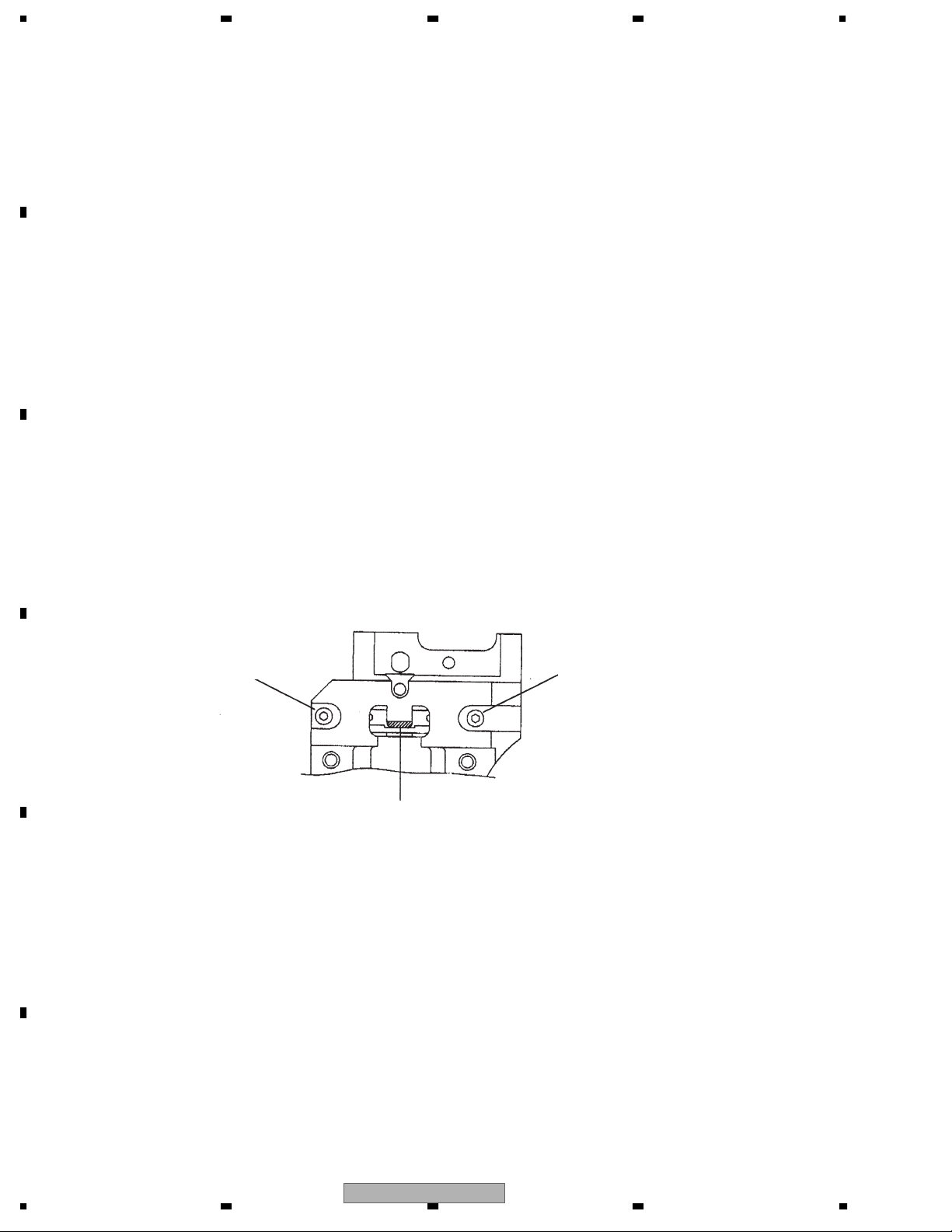
PU diagram
Skew adjustment screw A
Screw rock(GYL1001)
D
Adhesive material
(GEM1033)
E
Skew adjustment screw B
Screw rock(GYL1001)
F
32
1234
AVIC-88DVD/UC

5678
GENERAL INFORMATION
DIAGNOSIS
DISASSEMBLY
- Handling the mechanical module
1. The mechanical module should be handled by holding
the upper frame and main frame of the mechanical module.
2. The front section of the upper frame is not very sturdy,
so this section should not be held too firmly (see fig.1).
A
B
- Removing the DVD Core Unit R
1. Bring the mechanism to a locked position (disk load
standby position).
2. Turn the mechanical module upside down.
3. Set the pick-up flexible cable to a shorted position on
the land end (the other is auxiliary), and turn the SW
knob in the direction opposite to OP (see fig.2).
4. Remove the pick-up flexible cable and the CRG flexible
cable from the connector. Remove the solder on the
lead wires of the load motor.
5. Remove screws at two locations, and remove the DVD
Core Unit R (lift the board in the direction of the white
arrow shown in fig.3, and remove it out diagonally).
Do not hold onto this area.
Auxiliary
land
DVD Core Unit R
Fig.1
Short
C
Fig.2
D
Fig.3
- Removing the PU unit (see fig.4)
1. Lift the pick-up rack to the center of the axis of the rack,
turn it 90 degrees first, then press on it lightly, and fix it
in place temporarily.
2. Remove the screw that keeps the main shaft clamp
spring in place, and remove the main shaft clamp
spring.
3. Remove the PU unit with the main shaft attached.
AVIC-88DVD/UC
56
Main shaft
clamp spring
PU rack
CRG motor
7
PU unit
Main shaft
Fig.4
8
E
F
33

A
1234
IC
*PE5324C
XAVINT, XADSCINT,
B
XADSCRES, XAVRES,
LOCKDET, CRGSENS,
TILT1/TILT, TILT3/CLOCK,
XODCRES, AVREFOFF
C
OPENSENS, EJECTSENS,
CRGADIN, FOK, RFENV,
NMI
RESERVED, CTS
DTR
EDCF, TMODE,
LTFEP
OFTR
SOCOMN
SICOMN
SCKCOMN
SLVSTS
HSTCMD
LTDA C
TXPC
RXPC
SOADSC
SIADSC
SCKADSC
LCDRFOFF
TILT2/BIAS
DISCSENS, TEMP
AVREF
AVSS
IRQPWR
INTC
RPU
SIO
UART0/CSI0
UART1/CSI1
UART2
CSI2
PWM0
PWM1
ADC
ROM
256k
BYTE
RAM
10k
BYTE
PC
32bit
Ballel Sifter
System
Register
General
Register
(32bit X 32)
CPU
Multiplier
(32 X 32 64)
ALU
PORT
BCU
Instruction
Queue
MEMC
DRAMC
ROMC
DMAC
System
Controller
CG
AMUTE
BMUTE
XCSAVW, XCSSRAM
XCSFLSH, BUSISO
RESERVED, XCSAVR
DISCDET
XCSODC
FS44_48
DACINPUT
EJECT
XLBE
XUBE
XUCHKENT
VERENT
CD/DVD
XRD
LOAD
XUWR
XLWR
MCKENA
WAITODC
A0-A20
D0-D15
EMPH, DISCSET,
VCONTA, VCONTB
XODCINT1, XODCINT0,
CDLOCK, FG
ADSCENS, ADSCENC,
CONT, OEIC
CKSEL
CLKOUT
X1
X2
CVDD
CVSS
MODE0-MODE2
XRESET
VDD
VSS
D
IC's marked * are MOS type.
Be careful in handling them because they are very
E
F
34
1234
AVIC-88DVD/UC
liable to be damaged by electrostatic induction.

*PD6378D
5678
A15
A14
A13
A12
A11
A10
A9
A8
NC
NC
we
reset
NC
NC
RY/by
NC
A17
A7
A6
A5
A4
A3
A2
A1
A16
1
2
3
4
5
6
7
8
9
10
11
12
13
14
15
16
17
18
19
20
21
22
23
24
A-1,A0-A17 : Address output
DQ0-DQ15 : Data input/output
ce : Chip enable input
oe : Output enable output
we : Write enable output
reset : Connect to VCC
RY/by : Not used
byte : Connect to VCC
VCC : Supply voltage
VSS : GND
NC : Not used
48
47
46
45
44
43
42
41
40
39
38
37
36
35
34
33
32
31
30
29
28
27
26
25
byte
VSS
DQ15/A-1
DQ7
DQ14
DQ6
DQ13
DQ5
DQ12
DQ4
VCC
DQ11
DQ3
DQ10
DQ2
DQ9
DQ1
DQ8
DQ0
oe
VSS
ce
A0
A
B
C
D
E
F
56
AVIC-88DVD/UC
7
8
35
 Loading...