

Page 1
E-STOP relays, safety gate monitors
Up to PL e of EN ISO 13849-1
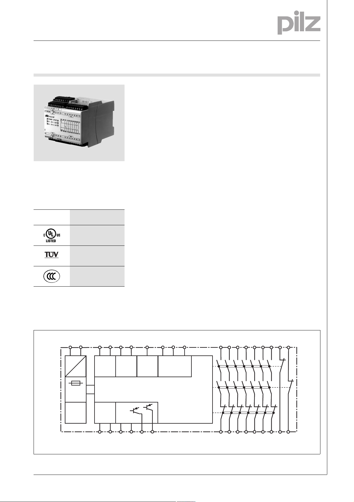
PNOZ X9P
Gertebild
][Bildunterschrift_NOT_Sch.tuer_Licht
Safety relay for monitoring E-STOP
pushbuttons, safety gates and light
beam devices
Approvals
PNOZ X9P
SÜDDEUTSCHLAND
Zulassungen
Order no. 777607 is without approval
Unit features
Gertemerkmale
` Positive-guided relay outputs:
– 7 safety contacts (N/O), instanta-
neous
– 2 auxiliary contacts (N/C), in-
stantaneous
` 2 semiconductor outputs
` Connection options for:
– E-STOP pushbutton
– Safety gate limit switch
– Light barriers
– Reset button
` LED indicator for:
– Switch status channel 1/2
– Input circuits
– Supply voltage
– Reset circuit
` Semiconductor outputs signal:
– Switch status channel 1/2
– Supply voltage is present
` Plug-in connection terminals (either
spring-loaded terminal or screw
terminal)
` See order reference for unit types
Unit description
Bestimmung/Gertebesc hreibung NOT-AUS , Schutzt, Lichtsc hr_PNOZ
The safety relay meets the requirements of EN 60947-5-1, EN 60204-1
and VDE 0113-1 and may be used in
applications with
` E-STOP pushbuttons
` Safety gates
` Light beam devices
Safety features
][Sicherheitseigenscha ften Schaltgerät_allgem einer Teil
The relay meets the following safety
requirements:
` The circuit is redundant with built-in
self-monitoring.
` The safety function remains effec-
tive in the case of a component failure.
` The correct opening and closing of
the safety function relays is tested
automatically in each on-off cycle.
Sicherheitseigenschaften Zusatz - Sicherung DC_PNOZ
` The unit has an electronic fuse.
Block diagram
Blockschaltbild
A1 (B1) A2 (B2) S52 13 23 33 43
A1 (B1) A2 (B2) S52 13 23 33 43
=
=
(~)*
(~)*
Power
Power
S11 S12 S21 S22
S11 S12 S21 S22
=
=
Feed-
Feed-
back
back
Y1 Y2
Y1 Y2
InputInput
InputInput
0 V
0 V
Y30 Y31 Y32 Y35
Y30 Y31 Y32 Y35
24 V/
24 V/
12 V
12 V
Input
Input
Reset/
Reset/
Start
Start
S37S33 S34
S37S33 S34
*Only applies when UB = 100 - 240 VAC
Pilz GmbH & Co. KG, Felix-Wankel-Straße 2, 73760 Ostfildern, Germany
Telephone: +49 711 3409-0, Telefax: +49 711 3409-133, E-Mail: pilz.gmbh@pilz.de
K1
K1
K2
K2
K3
K3
14 24 34 44
14 24 34 44
53 63 73 81 91
53 63 73 81 91
54 64 74 82 92
54 64 74 82 92
NSG-D-2-169-2010-08
Page 2
E-STOP relays, safety gate monitors
Up to PL e of EN ISO 13849-1
PNOZ X9P
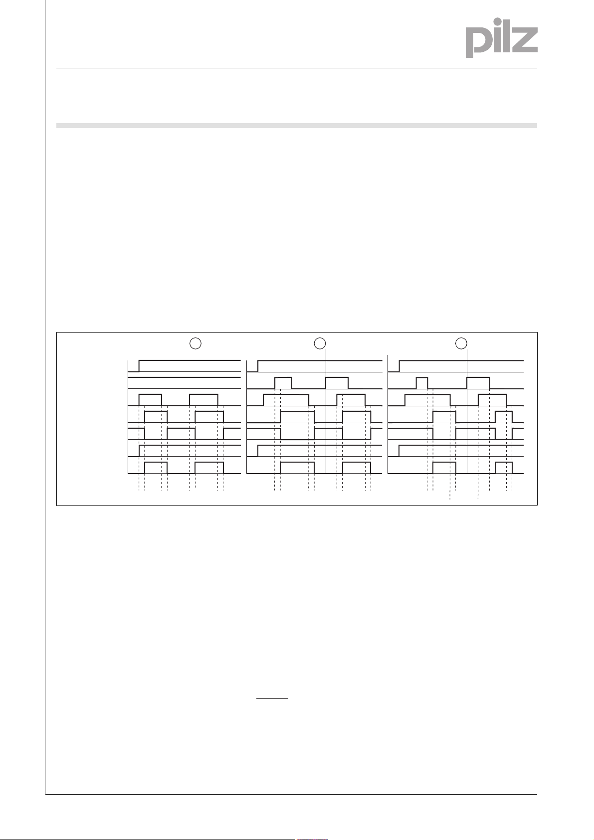
Function description
][Funktionen_einkanalig
` Single-channel operation: no re-
dundancy in the input circuit, earth
faults in the reset and input circuit
are detected.
][Funktionen_zweikanalig_ohne_quer
` Dual-channel operation without de-
tection of shorts across contacts:
redundant input circuit, detects
– earth faults in the reset and input
circuit,
– short circuits in the input circuit
and, with a monitored reset, in
the reset circuit too.
][Funktionen_zweikanalig_mit_quer_ber
Timing diagram
1 2
POWER
Reset/Start
Input
Output safe
` Dual-channel operation with detec-
tion of shorts across contacts: redundant input circuit, detects
– earth faults in the reset and input
circuit,
– short circuits in the input circuit
and, with a monitored reset, in
the reset circuit too,
– shorts between contacts in the
input circuit.
][Funktionen_autoStart
` Automatic start: Unit is active once
the input circuit has been closed.
][Funktionen_manuStart
][Zeitdiagramm_auto_manu_ueber1_aux_semiRUN_semiCH
ab
` Manual reset: Unit is active once
the input circuit is closed and then
the reset circuit is closed.
][Funktionen_berStart_allg
` Monitored reset: Unit i s ac t iv e o nc e
– the input circuit is closed and
then the reset circuit is closed
and opened again.
– the reset circuit is closed and
then opened again once the input circuit is closed.
][Funktionen_Kontaktvervielfachung
` Increase in the number of available
instantaneous safety contacts by
connecting contact expansion
modules or external contactors.
ab
3
Output aux.
Out semi RUN
Out semi CH
t1 t2
t1 t2
Key
` Power: Supply voltage
` Reset/Start: Reset circuit S33-S34
` Input: Input circuits S11-S12, S21-
S22, S52
` Output safe: Safety contacts 13-14,
23-24, 33-34, 43-44, 53-54, 63-64,
73-74
` Output aux: Auxiliary contacts 81-
82, 91-92
Wiring
][Verdrahtung_Si_Hi_unverz
Please note:
` Information given in the “Technical
details” must be followed.
` Outputs 13-14, 23-24, 33-34, 43-
44, 53-54, 63-64, 73-74 are safety
contacts, outputs 81-82, 91-92 are
auxiliary contacts (e.g. for display).
` To prevent contact welding, a fuse
should be connected before the
output contacts (see technical details).
t1
t1
t2
` Out semi RUN: Semiconductor out-
put supply voltage Y35
` Out semi CH: Semiconductor out-
put switch status Y32
` c: Automatic reset
` d: Manual reset
` e: Monitored reset
` a: Input circuit closes before reset
circuit
` Calculation of the max. cabling runs
in the input circuit:
l
max
R
lmax
=
I
max
Rl / km
R
= max. overall cable resist-
lmax
ance (see technical details)
/km = cable resistance/km
R
l
` Use copper wire that can withstand
60/75 °C.
t2
t1
t2
t1
t3
` b: Reset circuit closes before input
circuit
: Switch-on delay
` t
1
: Delay-on de-energisation
` t
2
: Recovery time
` t
3
` Sufficient fuse protection must be
provided on all output contacts with
capacitive and inductive loads.
t2
Telephone: +49 711 3409-0, Telefax: +49 711 3409-133, E-Mail: pilz.gmbh@pilz.de
NSG-D-2-169-2010-08Pilz GmbH & Co. KG, Felix-Wankel-Straße 2, 73760 Ostfildern, Germany
-2
Page 3
E-STOP relays, safety gate monitors
Up to PL e of EN ISO 13849-1
PNOZ X9P
Preparing for operation
Betriebsbereitschaft her stellen
` Supply voltage
Supply voltage AC DC
= 12 VDC/24 VDC/100 – 240 VAC
U
B
U
= 12 VDC/24 VDC
B
A1
A2
L1
N
PE
` Input circuit
Input circuit Single-channel Dual-channel
E-STOP
without detection of shorts across contacts
S21
S22
S11
S12
S52
S1
S21
S22
B1
B2
A1
A2
S11
S12
S52
L+
L-
L+
L-
S1
E-STOP
with detection of shorts across contacts
Safety gate
without detection of shorts across contacts
Safety gate
with detection of shorts across contacts
Light beam device with detection of shorts
across contacts via ESPE
S21
S22
S11
S12
S52
S1
S21
S22
S21
S22
S11
S52
S11
S52
S12
S52
S11
S12
S52
S11
S12
S21
S22
S11
S21
S22
S12
S1
S1
S1
S2
S2
24 V DC
GND
Pilz GmbH & Co. KG, Felix-Wankel-Straße 2, 73760 Ostfildern, Germany
Telephone: +49 711 3409-0, Telefax: +49 711 3409-133, E-Mail: pilz.gmbh@pilz.de
NSG-D-2-169-2010-08
Page 4

E-STOP relays, safety gate monitors
Up to PL e of EN ISO 13849-1
PNOZ X9P
` Reset circuit
Reset circuit E-STOP/safety gate wiring (single-channel
and dual-channel without shorts across
contacts)
Automatic reset
Manual reset
Monitored reset
S33
S34
S3
S33
S34
S3
S33
S34
Y1
S37
` Feedback circuit
Feedback circuit
Contacts from external contactors
13 (23 ... 73)
14 (24 ... 74)
E-STOP/safety gate wiring
(dual-channel with shorts across contacts)
S12
S34
S12
S34
S12
S34
Y1
S37
Y1
Y2
K5
K6
K5
K6
L1
N
S3
S3
` Semiconductor output
Y31
Y32
Y35
Y30
24 V DC/12 V DC
SPS Input
SPS Input
0 V
` Key
S1/S2 E-STOP/safety gate switch
S3 Reset button
Switch operated
Gate open
Gate closed
Telephone: +49 711 3409-0, Telefax: +49 711 3409-133, E-Mail: pilz.gmbh@pilz.de
NSG-D-2-169-2010-08Pilz GmbH & Co. KG, Felix-Wankel-Straße 2, 73760 Ostfildern, Germany
-4
Page 5

E-STOP relays, safety gate monitors
Up to PL e of EN ISO 13849-1
PNOZ X9P
Terminal configuration
Klemmenbelegung
UB = 12 VDC/24 VDC
A1 S33 S34 S33 81 81 91 13 23 33 43 53 63 73
PNOZ X9P
POWER
IN IN -
Y1
Y30 Y32Y31 Y35
U
= 24 VDC/100 -240 VAC
B
A1 B1 S33 S33 81 81 91 13 23 33 43 53 63 73
PNOZ X9P AC
POWER
IN IN -
CH. 1
CH. 2
S34
CH. 1
CH. 2
P3
P4
P4
P3
P3
P4
START
- OUT
- OUT
START
- OUT
- OUT
Y2Y1S12S11 S22S12 S21
S11 S52
Y2Y1S12S11 S22S12S21
81
81
82
82
14A2 82S37 82 92 744424 34 54 64
81
81
P5
2313 33
2414 34
P5
P5
2313 33
735343 6391
745444 6492
735343 6391
Installation
Montage_PNOZ_X
` The safety relay should be installed
in a control cabinet with a protection type of at least IP54.
` Use the notch on the rear of the unit
to attach it to a DIN rail.
` Ensure the unit is mounted securely
on a vertical DIN rail (35 mm) by using a fixing element (e.g. retaining
bracket or an end angle).
20162
Y1
B2
Y30 Y32Y31 Y35
P4
P3
Dimensions
Abmessungen
* with spring-loaded terminals
94 (3.70")
* 101 (3.98")
S11 S52
82
82
14A2 82S37 82 92 744424 34 54 64
121 (4.76")
2414 34
P5
90
(3.54")
745444 6492
Pilz GmbH & Co. KG, Felix-Wankel-Straße 2, 73760 Ostfildern, Germany
Telephone: +49 711 3409-0, Telefax: +49 711 3409-133, E-Mail: pilz.gmbh@pilz.de
NSG-D-2-169-2010-08
Page 6

E-STOP relays, safety gate monitors
Up to PL e of EN ISO 13849-1
PNOZ X9P
Notice
][WICHTIG_PDB_al t
This data sheet is only intended for use
during configuration. For installation
and operation, please refer to the operating instructions supplied with the
unit.
][Technische Daten PNOZ
Service life graph
10
1
D Nennbetriebstrom (A)
GB Nominal operating current (A)
F Courant coupé (A)
0.1
E Corriente nominal de servicio (A)
I Corrente di esercizio nominale (A)
NL Nominale bedrijfsstroom (A)
10 100 1000 10000
D Schaltspielzahl x 10
GB Cycles x 10
F Nombre de manuvres x 10
DC13: 24 V
3
AC1: 230 V
3
Lebensdauerkurve
DC1: 24 V
AC1: 400 V
AC15: 230 V
E Número de ciclos x 10
I Numero dei cicli di commutazione x 10
3
NL Aantal schakelingen x 10
Technical details
Electrical data
Supply voltage
Supply voltage U
Supply voltage U
AC 100 - 240 V
B
DC 12 V, 24 V
B
Voltage tolerance -15 %/+10 % No. 777606, 777609, 787606, 787609
-20 %/+20 % No. 777607
Power consumption at U
Power consumption at U
AC 8.5 VA No. 777606, 787606
B
DC 5.5 W No. 777606, 777609, 787606, 787609
B
7.0 W No. 777607
Frequency range AC 50 - 60 Hz
Residual ripple DC 160 %
Voltage and current at
Input circuit DC: 12.0 V No. 777607
24.0 V No. 777606, 777609, 787606, 787609
Reset circuit DC: 12.0 V No. 777607
24.0 V No. 777606, 777609, 787606, 787609
Feedback loop DC: 12.0 V No. 777607
24.0 V No. 777606, 777609, 787606, 787609
130.0 mA No. 777607
50.0 mA No. 777606, 777609, 787606, 787609
100.0 mA No. 777606, 777609, 787606, 787609
200.0 mA No. 777607
100.0 mA No. 777606, 777609, 787606, 787609
200.0 mA No. 777607
Number of output contacts
Safety contacts (S) instantaneous: 7
Auxiliary contacts (N/C): 2
Utilisation category in accordance with EN 60947-4-1
Safety contacts: AC1 at 240 V I
Safety contacts: DC1 at 24 V I
Auxiliary contacts: AC1 at 240 V I
Auxiliary contacts: DC1 at 24 V I
: 0.01 A , I
min
: 2000 VA
P
max
: 0.01 A , I
min
P
: 200 W
max
: 0.01 A , I
min
P
: 2000 VA
max
: 0.01 A , I
min
: 200 W
P
max
max
max
max
max
: 8.0 A
: 8.0 A
: 8.0 A
: 8.0 A
Utilisation category in accordance with EN 60947-5-1
Safety contacts: AC15 at 230 V I
Safety contacts: DC13 at 24 V (6 cycles/min) I
Auxiliary contacts: AC15 at 230 V I
Auxiliary contacts: DC13 at 24 V (6 cycles/min) I
max
max
max
max
: 5.0 A
: 7.0 A
: 5.0 A
: 7.0 A
Contact material AgSnO2 + 0.2 µm Au
3
3
3
Telephone: +49 711 3409-0, Telefax: +49 711 3409-133, E-Mail: pilz.gmbh@pilz.de
NSG-D-2-169-2010-08Pilz GmbH & Co. KG, Felix-Wankel-Straße 2, 73760 Ostfildern, Germany
-6
Page 7

E-STOP relays, safety gate monitors
Up to PL e of EN ISO 13849-1
PNOZ X9P
Electrical data
External contact fuse protection (IK = 1 kA) to EN 60947-5-1
Blow-out fuse, quick
Safety contacts: 10 A
Auxiliary contacts: 10 A
Blow-out fuse, slow
Safety contacts: 6 A
Auxiliary contacts: 6 A
Circuit breaker 24 VAC/DC, characteristic B/C
Safety contacts: 6 A
Auxiliary contacts: 6 A
Semiconductor outputs (short circuit proof) 12.0 V No. 777607
24.0 V No. 777606, 777609, 787606, 787609 DC, 20 mA
External supply voltage 12.0 V No. 777607
24.0 V No. 777606, 777609, 787606, 787609 DC
Voltage tolerance -20 %/+20 %
Max. overall cable resistance R
input circuits, reset circuits
single-channel at U
single-channel at U
dual-channel without detect. of shorts across contacts at U
dual-channel without detect. of shorts across contacts at U
dual-channel with detect. of shorts across contacts at U
dual-channel with detect. of shorts across contacts at U
Min. input resistance in the starting torque 89 Ohm No. 777609, 787609
Safety-related characteristic data
PL in accordance with EN ISO 13849-1 PL e (Cat. 4)
Category in accordance with EN 954-1 Cat. 4
SIL CL in accordance with EN IEC 62061 SIL CL 3
PFH in accordance with EN IEC 62061 2.31E-09
SIL in accordance with IEC 61511 SIL 3
PFD in accordance with IEC 61511 2.03E-06
t
in years 20
M
Times
Switch-on delay
with automatic reset typ. 130 ms No. 777607
with automatic reset max. 200 ms No. 777607
with automatic reset after power on typ. 150 ms No. 777607
with automatic reset after power on max. 220 ms No. 777607
with manual reset typ. 150 ms No. 777607
with manual reset max. 200 ms No. 777607
on monitored reset with falling edge typ. 100 ms No. 777607
on monitored reset with falling edge max. 150 ms No. 777607
DC 45 Ohm No. 777606, 777609, 787606, 787609
B
AC 45 Ohm No. 777606, 787606
B
lmax
8 Ohm No. 777607
DC 15 Ohm No. 777607
B
90 Ohm No. 777606, 777609, 787606, 787609
AC 90 Ohm No. 777606, 787606
B
DC 15 Ohm No. 777606, 777609, 787606, 787609
B
AC 15 Ohm No. 777606, 787606
B
8 Ohm No. 777607
9 Ohm No. 777607
200 ms No. 777606, 777609, 787606, 787609
250 ms No. 777606, 777609, 787606, 787609
220 ms No. 777606, 777609, 787606, 787609
300 ms No. 777606, 777609, 787606, 787609
200 ms No. 777606, 777609, 787606, 787609
250 ms No. 777606, 777609, 787606, 787609
150 ms No. 777606, 777609, 787606, 787609
220 ms No. 777606, 777609, 787606, 787609
Pilz GmbH & Co. KG, Felix-Wankel-Straße 2, 73760 Ostfildern, Germany
Telephone: +49 711 3409-0, Telefax: +49 711 3409-133, E-Mail: pilz.gmbh@pilz.de
NSG-D-2-169-2010-08
Page 8

E-STOP relays, safety gate monitors
Up to PL e of EN ISO 13849-1
PNOZ X9P
Times
Delay-on de-energisation
with E-STOP typ. 20 ms
with E-STOP max. 30 ms
with power failure typ. 170 ms No. 777606, 777609, 787606, 787609
60 ms No. 777607
with power failure max. 250 ms No. 777606, 777609, 787606, 787609
80 ms No. 777607
with power failure typ. U
with power failure max. U
with power failure typ. U
with power failure max. U
Recovery time at max. switching frequency 1/s
after E-STOP 50 ms
after power failure 100 ms No. 777607
after power failure on universal power supply 500 ms No. 777606, 787606
Min. start pulse duration with a monitored reset
with falling edge 30 ms No. 777607
Simultaneity, channel 1 and 2 150 ms No. 777606, 777609, 787606, 787609
Supply interruption before de-energisation 20 ms
Environmental data
EMC EN 60947-5-1, EN 61000-6-2
Vibration to EN 60068-2-6
Frequency 10 - 55 Hz
Amplitude 0.35 mm
Climatic suitability EN 60068-2-78
Airgap creepage in accordance with EN 60947-1
Pollution degree 2
Overvoltage category III
Rated insulation voltage 250 V
Rated impulse withstand voltage 4.00 kV
Ambient temperature -10 - 55 °C
Storage temperature -40 - 85 °C
Protection type
Mounting (e.g. cabinet) IP54
Housing IP40
Terminals IP20
Mechanical data
Housing material
Housing PPO UL 94 V0
Front ABS UL 94 V0
Cross section of external conductors with screw terminals
1 core flexible 0.25 - 2.50 mm² , 24 - 12 AWG No. 777606, 777607, 777609
2 core, same cross section, flexible:
with crimp connectors, without insulating sleeve 0.25 - 1.00 mm² , 24 - 16 AWG No. 777606, 777607, 777609
without crimp connectors or with TWIN crimp connectors 0.20 - 1.50 mm² , 24 - 16 AWG No. 777606, 777607, 777609
Torque setting with screw terminals 0.50 Nm No. 777606, 777607, 777609
Cross section of external conductors with spring-loaded termi-
nals: Flexible with/without crimp connectors
Spring-loaded terminals: Terminal points per connection 2 No. 787606, 787609
Stripping length 8 mm No. 787606, 787609
AC: 100 V, 100 V 165 ms No. 777606, 787606
B
AC: 100 V, 100 V 200 ms No. 777606, 787606
B
AC : 240 V 320 ms No. 777606, 787606
B
AC : 240 V 450 ms No. 777606, 787606
B
300 ms No. 777606, 777609, 787606, 787609
50 ms No. 777606, 777609, 787606, 787609
50 ms No. 777607
0.20 - 1.50 mm² , 24 - 16 AWG No. 787606, 787609
Telephone: +49 711 3409-0, Telefax: +49 711 3409-133, E-Mail: pilz.gmbh@pilz.de
NSG-D-2-169-2010-08Pilz GmbH & Co. KG, Felix-Wankel-Straße 2, 73760 Ostfildern, Germany
-8
Page 9

E-STOP relays, safety gate monitors
Up to PL e of EN ISO 13849-1
PNOZ X9P
Mechanical data
Dimensions
Height 101.0 mm No. 787606, 787609
94.0 mm No. 777606, 777607, 777609
Width 90.0 mm
Depth 121.0 mm
Weight 570 g No. 787609
575 g No. 787606
580 g No. 777607, 777609
Technische Daten_Satz No .
No. stands for order number.
Technische Daten_Satz No rmen
The standards current on 2009-11 apply.
][Dauerstrom_ACDC
Conventional thermal current
585 g No. 777606
Number of contacts I
1 8.00 A 8.00 A No. 777606, 787606
2 8.00 A 8.00 A No. 777606, 787606
3 8.00 A 8.00 A No. 777606, 787606
4 7.00 A 7.00 A No. 777606, 787606
5 6.00 A 6.00 A No. 777606, 787606
6 5.50 A 5.50 A No. 777606, 787606
7 5.00 A 5.00 A No. 777606, 787606
Order reference
Type Features Terminals Order no.
PNOZ X9P C 110 - 240 VAC 24 VDC Spring-loaded terminals 787 606
PNOZ X9P 110 - 240 VAC 24 VDC Screw terminals 777 606
PNOZ X9P C 24 VDC Spring-loaded terminals 787 609
PNOZ X9P 24 VDC Screw terminals 777 609
PNOZ X9P 12 VDC Screw terminals 777 607
(A) at UBDC Ith(A) at UBAC
th
Bestelldaten
Pilz GmbH & Co. KG, Felix-Wankel-Straße 2, 73760 Ostfildern, Germany
Telephone: +49 711 3409-0, Telefax: +49 711 3409-133, E-Mail: pilz.gmbh@pilz.de
NSG-D-2-169-2010-08
 Loading...