

Contact expansion modules
up to PL c of EN ISO 13849-1
PNOZ s8
Gertebild
][Bildunterschrift Kontakterweiterungen
Contact expansion module for increasing the number of available contacts
Approvals
PNOZ s8
SÜDDEUTSCHLAND
Zulassungen
Unit features
Gertemerkmale
` Relay outputs:
– 2 safety contacts (N/O), instanta-
neous
` 1 semiconductor output
` LED indicator for:
– Input status, channel 1
– Input status, channel 2
– Switch status of the safety con-
tacts
– Error
` Plug-in connection terminals (either
spring-loaded terminal or screw
terminal)
Unit description
Bestimmung/Gertebesch reibung Kontakter weiterungen Schalt _PNOZ
The unit meets the requirements of
EN 60947-5-1, EN 60204-1 and
VDE 0113-1. The contact expansion
module is used to increase the number
of instantaneous safety contacts available on a base unit. Base units are all
safety relays with feedback loop monitoring.
The category that can be achieved in
accordance with EN 954-1 and
EN ISO 13849-1 depends on the category of the base unit. The contact expansion module may not exceed this.
Safety features
Safety features
The unit meets the following safety requirements:
` The unit monitors its own output
contacts.
` The safety function remains effec-
tive in the case of a component failure.
` Earth fault in the feedback loop:
Detected, depending on the base
unit that is used.
` Earth fault in the input circuit:
The output relays de-energise and
the safety contacts open.
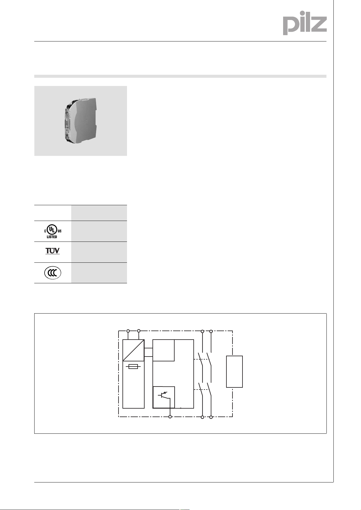
Block diagram
Blockschaltbild
A1 A2
=
Power
=
Input
Y32
K1
K2
13
14
23
24
unit
Interface
expansion
Pilz GmbH & Co. KG, Felix-Wankel-Straße 2, 73760 Ostfildern, Germany
Telephone: +49 711 3409-0, Telefax: +49 711 3409-133, E-Mail: pilz.gmbh@pilz.de
NSG-D-2-399-2010-10
Contact expansion modules
up to PL c of EN ISO 13849-1
PNOZ s8
Function description
][Funktionsbeschreibung_Erweiterungsgert
with PNOZsigma base unit:
` Dual-channel operation via
PNOZsigma connector
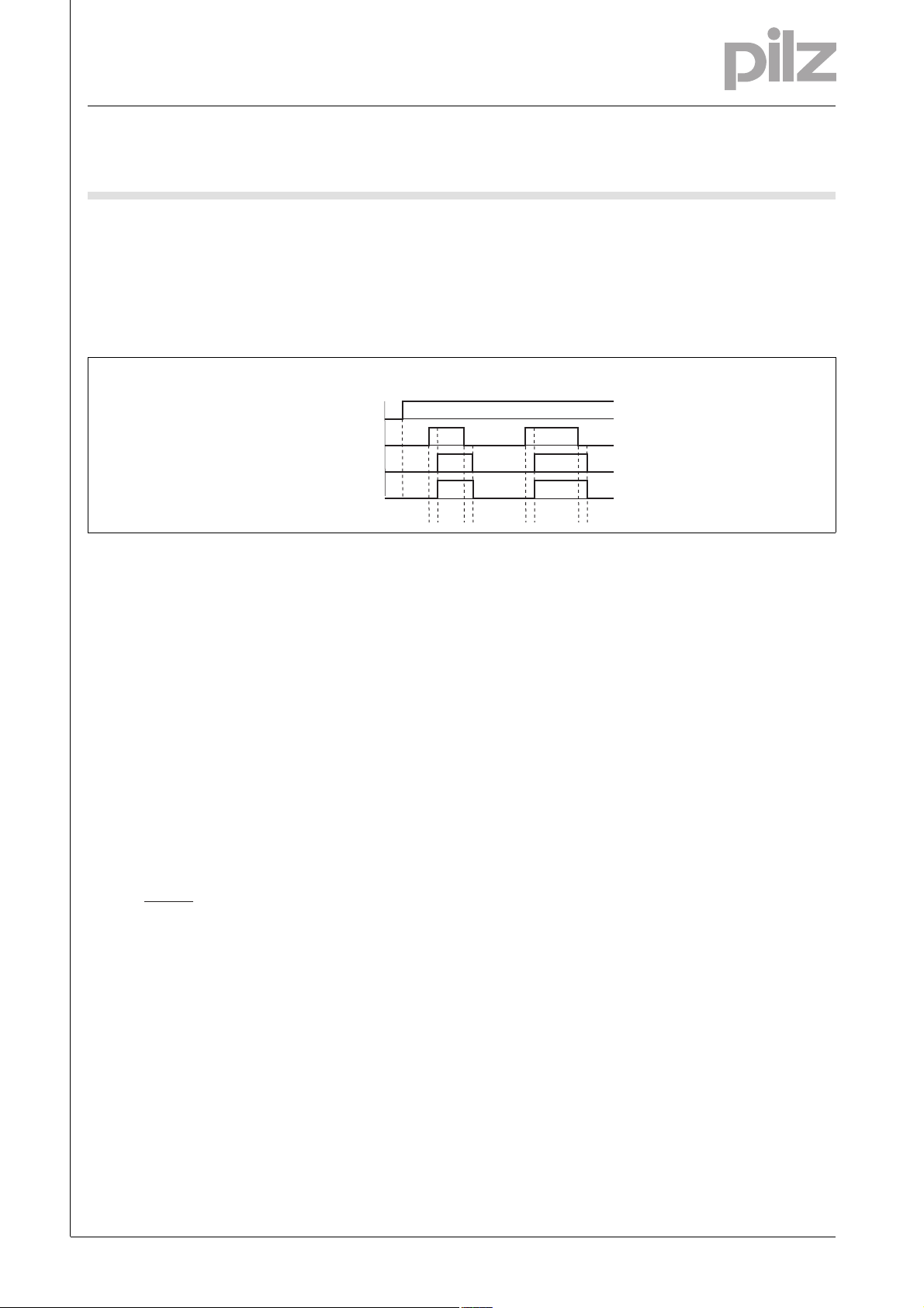
Timing diagram
Output safe
Key
` Power: Supply voltage
` Input: Input circuits A1
` Output safe: Safety contacts 13-14,
23-24
Wiring
without PNOZsigma base unit:
` Single-channel operation: one input
circuit affects the output relays
Zeitdiagramm
POWER
Input
Out semi
t1 t1t2 t2
` Out semi: Semiconductor output
Y32
: Switch-on delay
` t
1
` t
: Delay-on de-energisation
2
][Verdrahtung_Si_unverz
Please note:
` Information given in the “Technical
details” must be followed.
` Outputs 13-14, 23-24 are safety
contacts.
` To prevent contact welding, a fuse
should be connected before the
output contacts (see technical details).
` Calculation of the max. cable runs
in the input circuit:
l
max
R
lmax
=
I
max
Rl / km
R
= max. overall cable resist-
lmax
ance (see technical details)
/km = cable resistance/km
R
l
` Use copper wire that can withstand
60/75 °C.
` Sufficient fuse protection must be
provided on all output contacts with
capacitive and inductive loads.
Telephone: +49 711 3409-0, Telefax: +49 711 3409-133, E-Mail: pilz.gmbh@pilz.de
NSG-D-2-399-2010-10Pilz GmbH & Co. KG, Felix-Wankel-Straße 2, 73760 Ostfildern, Germany
-2

Contact expansion modules
up to PL c of EN ISO 13849-1
PNOZ s8
Preparing for operation
Betriebsbereitschaft herstellen PNOZs
` Supply voltage
Supply voltage AC DC
24 V DC
0 V
` Input circuit
Input circuit Single-channel Dual-channel
Base unit:
PNOZ X safety relay
Base unit:
PNOZelog safety relay
Driven via semiconductor outputs
(24 VDC)
24 V DC
0 V
O1
PNOZsigma
A1
expansion
A2
module
PNOZsigma
A1
expansion
module
A20 V
L-
PNOZsigma
A1
expansion
A2
module
` Feedback loop
with PNOZsigma base unit:
The feedback loop is connected and
evaluated via the connector.
without PNOZsigma base unit:
Feedback loop does not need to be
monitored because the contact ex-
` Semiconductor output
Y32
*Connect together the 0V connections on all the external power supplies
][Betriebsbereitschaft_herstellen_Info_Erweiterungsgert_DB
INFORMATION
If a base unit and a contact expander
module from the PNOZsigma range
are connected via the connector, no
additional wiring is necessary.
Do not connect A1 to the contact expander module!
pansion block monitors its own output
contacts.
*
PLC Input
Pilz GmbH & Co. KG, Felix-Wankel-Straße 2, 73760 Ostfildern, Germany
Telephone: +49 711 3409-0, Telefax: +49 711 3409-133, E-Mail: pilz.gmbh@pilz.de
NSG-D-2-399-2010-10

Contact expansion modules
up to PL c of EN ISO 13849-1
PNOZ s8
Terminal configuration
Klemmenbelegung
Installation
][Montage_PNOZsigma Erweiterungsgert
Install contact expander module
without base unit:
` Ensure that the plug terminator is
inserted at the side of the unit.
Connect base unit and PNOZsigma
contact expander module:
` Remove the plug terminator at the
side of the base unit and at the contact expander module
` Connect the base unit and the con-
tact expander module to the supplied connector before mounting
the units to the DIN rail.
Installation in control cabinet
` The safety relay should be installed
in a control cabinet with a protection type of at least IP54.
` Use the notch on the rear of the unit
to attach it to a DIN rail (35 mm).
` When installed vertically: Secure
the unit by using a fixing element
(e.g. retaining brakket or end angle).
` Push the unit upwards or down-
wards before lifting it from the DIN
rail.
Dimensions
Abmessungen
*with spring-loaded terminals
98 (3.86")
* 100 (3,94")
120 (4.72")
12,5 (0.69")
Telephone: +49 711 3409-0, Telefax: +49 711 3409-133, E-Mail: pilz.gmbh@pilz.de
NSG-D-2-399-2010-10Pilz GmbH & Co. KG, Felix-Wankel-Straße 2, 73760 Ostfildern, Germany
-4

Contact expansion modules
up to PL c of EN ISO 13849-1
PNOZ s8
NOTICE
][WICHTIG_PDB_al t
This data sheet is only intended for use
during configuration. For installation
and operation, please refer to the operating instructions supplied with the
unit.
Technical details
Electrical data
Supply voltage
Supply voltage U
Voltage tolerance -20 %/+20 %
Power consumption at U
Residual ripple DC 20 %
Voltage and current at
Input circuit DC: 24.0 V 65.0 mA
Number of output contacts
Safety contacts (S) instantaneous: 2
Utilisation category in accordance with EN 60947-4-1
Safety contacts: AC1 at 240 V I
Safety contacts: DC1 at 24 V I
Utilisation category in accordance with EN 60947-5-1
Safety contacts: AC15 at 230 V I
Safety contacts: DC13 at 24 V (6 cycles/min) I
Contact material AgSnO2
External contact fuse protection (I
Blow-out fuse, quick
Safety contacts: 4 A
Blow-out fuse, slow
Safety contacts: 2 A
Circuit breaker 24 VAC/DC, characteristic B/C
Safety contacts: 2 A
Semiconductor outputs (short circuit proof) 24.0 V DC, 20 mA
Max. overall cable resistance R
input circuits, reset circuits
single-channel at U
Safety-related characteristic data
PL in accordance with EN ISO 13849-1 PL c (Cat. 3)
Category in accordance with EN 954-1 Cat. 3
SIL CL in accordance with EN IEC 62061 SIL CL 2
PFH in accordance with EN IEC 62061 2.00E-07
SIL in accordance with IEC 61511 SIL 2
PFD in accordance with IEC 61511 6.35E-03
t
in years 20
M
Times
Switch-on delay
with automatic reset after power on typ. 100 ms
with automatic reset after power on max. 150 ms
Delay-on de-energisation
with E-STOP typ. 30 ms
with E-STOP max. 40 ms
with power failure typ. 30 ms
with power failure max. 40 ms
DC 24 V
B
DC 2.0 W
B
= 1 kA) to EN 60947-5-1
K
lmax
DC 30 Ohm
B
: 0.02 A , I
min
P
: 720 VA
max
: 0.02 A , I
min
: 72 W
P
max
: 1.5 A
max
: 1.5 A
max
max
max
Technical details PNOZsigma
: 3.0 A
: 3.0 A
Pilz GmbH & Co. KG, Felix-Wankel-Straße 2, 73760 Ostfildern, Germany
Telephone: +49 711 3409-0, Telefax: +49 711 3409-133, E-Mail: pilz.gmbh@pilz.de
NSG-D-2-399-2010-10

Contact expansion modules
up to PL c of EN ISO 13849-1
PNOZ s8
Environmental data
EMC EN 60947-5-1, EN 61000-6-2, EN 61000-6-4
Vibration to EN 60068-2-6
Frequency 10 - 55 Hz
Amplitude 0.35 mm
Climatic suitability EN 60068-2-78
Airgap creepage in accordance with EN 60947-1
Pollution degree 2
Overvoltage category III
Rated insulation voltage 250 V
Rated impulse withstand voltage 4.00 kV
Ambient temperature -10 - 55 °C
Storage temperature -40 - 85 °C
Protection type
Mounting (e.g. cabinet) IP54
Housing IP40
Terminals IP20
Mechanical data
Housing material
Housing PC
Front PC
Cross section of external conductors with screw terminals
1 core flexible 0.25 - 2.50 mm² , 24 - 12 AWG No. 750108
2 core, same cross section, flexible:
with crimp connectors, without insulating sleeve 0.25 - 1.00 mm² , 24 - 16 AWG No. 750108
without crimp connectors or with TWIN crimp connectors 0.20 - 1.50 mm² , 24 - 16 AWG No. 750108
Torque setting with screw terminals 0.50 Nm No. 750108
Cross section of external conductors with spring-loaded terminals: Flexible with/without crimp connectors
Spring-loaded terminals: Terminal points per connection 2 No. 751108
Stripping length 9 mm No. 751108
Dimensions
Height 102.0 mm No. 751108
Width 12.5 mm
Depth 120.0 mm
Weight 105 g
Technische Daten_Satz No .
No. stands for order number.
Si_Kennzahlen_Erläuterung
All the units used within a safety function must be considered when calculating the safety characteristic data.
Technische Daten_Satz No rmen
The standards current on 2006-04 apply.
][Dauerstrom_DC
0.20 - 2.50 mm² , 24 - 12 AWG No. 751108
98.0 mm No. 750108
Conventional thermal current
(A) at UBDC
I
th
1 contact 3.00 A
2 contacts 3.00 A
Order reference
Type Features Terminals Order no.
PNOZ s8 24 VDC With screw terminal 750 108
PNOZ s8 C 24 VDC With spring-loaded terminal 751 108
Telephone: +49 711 3409-0, Telefax: +49 711 3409-133, E-Mail: pilz.gmbh@pilz.de
Bestelldaten
NSG-D-2-399-2010-10Pilz GmbH & Co. KG, Felix-Wankel-Straße 2, 73760 Ostfildern, Germany
-6
 Loading...