

Page 1

PNOZ msi b4 Box
Accessories PNOZmulti
Operating Manual-1003058-EN-01
Page 2

Preface
This document is a translation of the original document.
All rights to this documentation are reserved by Pilz GmbH & Co. KG. Copies may be made
for internal purposes. Suggestions and comments for improving this documentation will be
gratefully received.
Pilz®, PIT®, PMI®, PNOZ®, Primo®, PSEN®, PSS®, PVIS®, SafetyBUS p®, SafetyEYE®,
SafetyNET p®, the spirit of safety® are registered and protected trademarks of Pilz GmbH
& Co. KG in some countries.
SD means Secure Digital
Page 3
PNOZ msi b4 Box
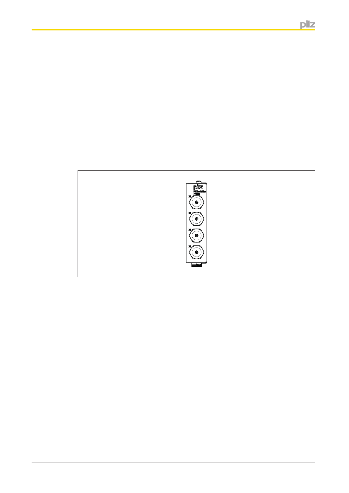
Description
The shielded junction box PNOZ msi b4 Box is used to connect
} An incremental encoder with an additional feed for the encoder supply
or
} An incremental encoder in conjunction with a proximity switch (dual encoder evaluation)
with an additional supply for the proximity switch
or
} 2 proximity switches with/without pull resistor with an additional supply for the proximity
switches
to the Pilz speed monitor.
Front view
Installation
} The junction box should be installed in a control cabinet with a protection type of at
least IP54.
} Fit the junction box to a horizontal mounting rail.
} Use the locking slide on the rear of the unit to attach the junction box to a mounting rail.
} In environments exposed to heavy vibration, the unit should be secured using a fixing
element (e.g. retaining bracket or end angle).
} Open the locking slide before lifting the unit from the mounting rail.
} Tighten the cable feeds with an SW 16 mm spanner.
Operating Manual PNOZ msi b4 Box
1003058-EN-01
3
Page 4
PNOZ msi b4 Box
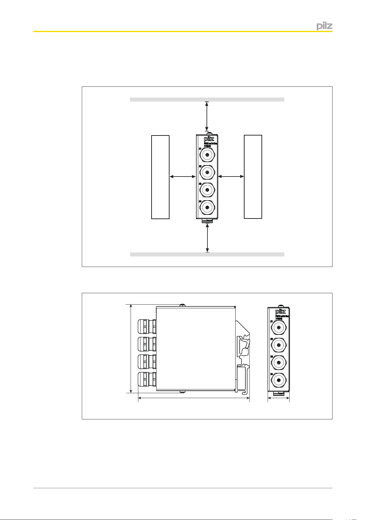
Mounting distances
For the wiring to be EMC-compliant, the junction box must maintain a distance of at least
5.5 mm from other conductive parts (e.g. adjacent housing parts) (see diagram).
5,5 mm
(0.22“)
Dimensions in mm
5,5 mm
(0.22“)
Conductive parts
5,5 mm
(0.22“)
Conductive parts
5,5 mm
(0.22“)
Operating Manual PNOZ msi b4 Box
1003058-EN-01
100 (3.94“)
126 (4.96“)
25 (0.98“)
4
Page 5

PNOZ msi b4 Box
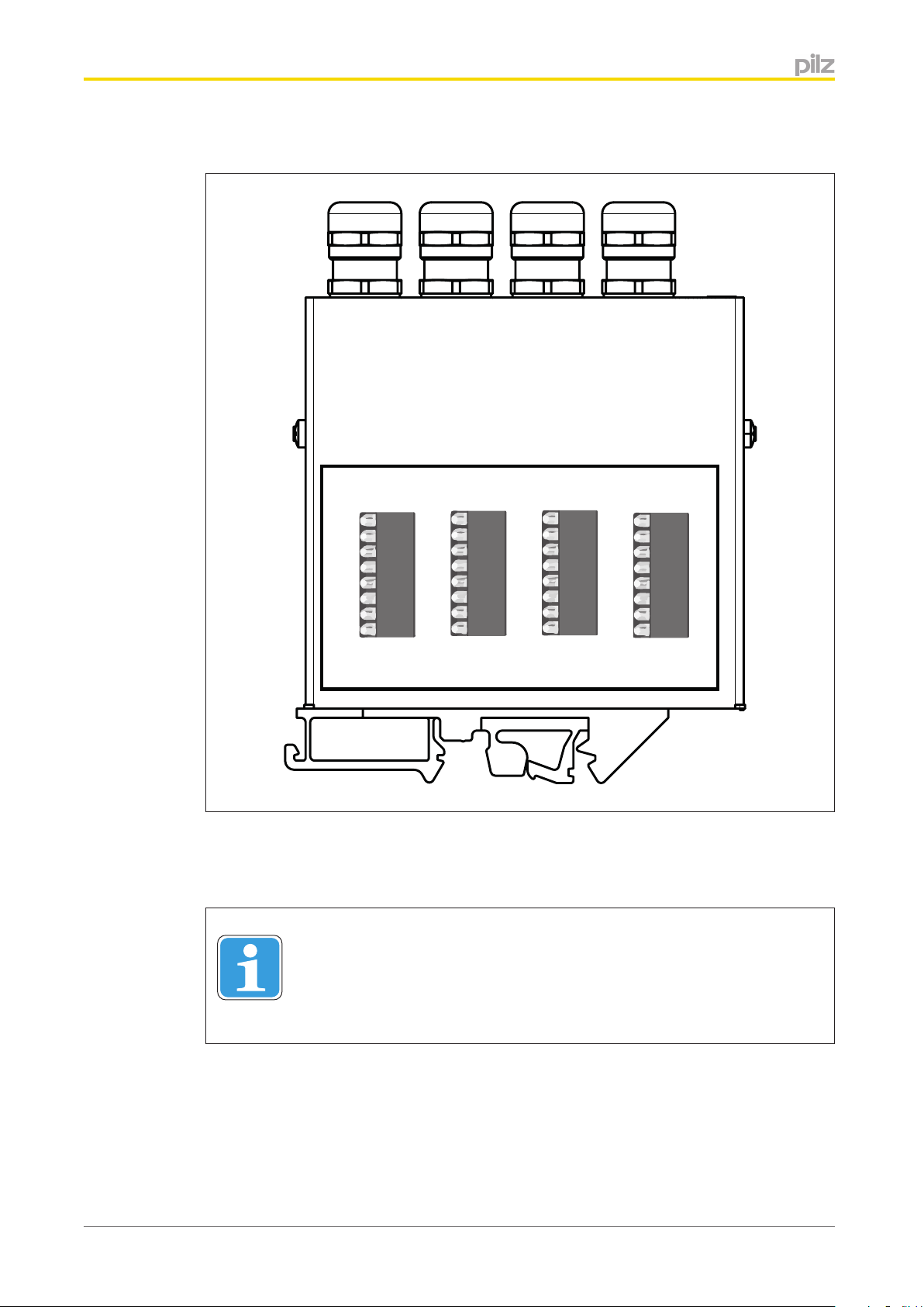
Connection
With shielded connection cables (external diameter: 3 to 7 mm), the shield must be fitted
over the cable gland. The following options are available:
Operating Manual PNOZ msi b4 Box
1003058-EN-01
5
Page 6
PNOZ msi b4 Box
Internal view
GND
S
24 V
24 V
B
24 V
Z
GND
X4
GND
24 V
24 V
GND
S
A
B
Z
GND
S
A
nA
B
nB
Z
nZ
GND
X3 X2 X1
S
A
nA
B
nB
Z
nZ
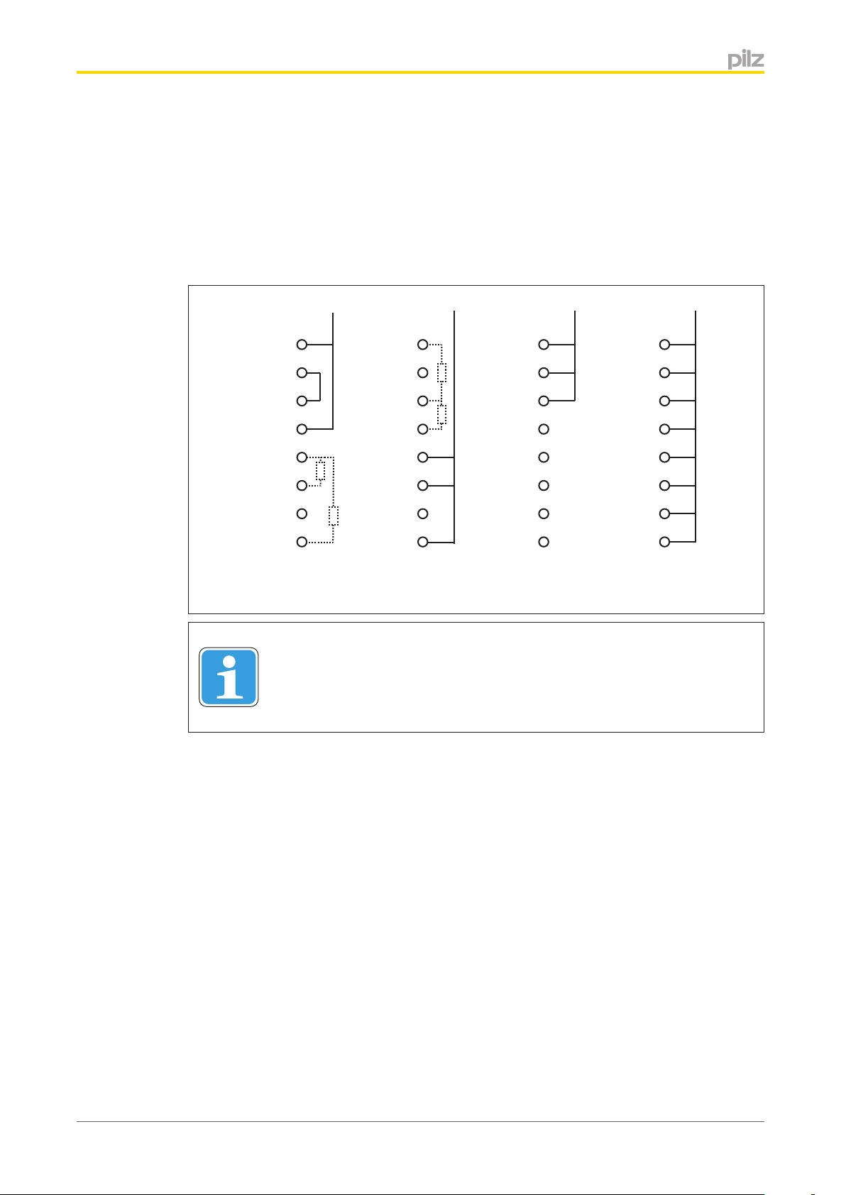
The cable feeds and the respective terminals are each labelled the same (X1 ... X4).
The signals of the same name (GND, S, 24 V....) are connected internally between termi-
nals X1 ... X4.
Information
Operating Manual PNOZ msi b4 Box
1003058-EN-01
If crimp connections are used, the connection wires can simply be plugged
into the spring terminal's plug connection. It's only necessary to press the
actuator button to undo the connection.
6
Page 7

PNOZ msi b4 Box
Connection examples
Wiring for the incremental encoder + supply voltage
Connection to the terminals
X1: Speed monitor
X2: Incremental encoder
X3: Supply voltage
GND
S
24 V
24 V
B
24 V
Z
GND
X4
GND
S
A
24 V
B
24 V
Z
GND
X3
GND
S
A
nA
B
nB
Z
nZ
X2
GND
S
A
nA
B
nB
Z
nZ
X1
Operating Manual PNOZ msi b4 Box
1003058-EN-01
7
Page 8

PNOZ msi b4 Box
Wiring for the incremental encoder + proximity switch on track Z (PNP) + supply voltage
Connection to the terminals
X1: Speed monitor
X2: Incremental encoder
X3: Proximity switch on track Z
X4: Supply voltage
GND
S
24 V
24 V
B
24 V
Z
GND
X4
GND
S
A
24 V
B
24 V
Z
GND
X3
GND
S
A
nA
B
nB
Z
nZ
X2
GND
S
A
nA
B
nB
Z
nZ
X1
Operating Manual PNOZ msi b4 Box
1003058-EN-01
8
Page 9
PNOZ msi b4 Box
Wiring for 2 proximity switches + supply voltage + pull resistor
Connection to the terminals
X1: Speed monitor
X2: Proximity switch 1
X3: Proximity switch 2
X4: Supply voltage
GND
S
24 V
24 V
B
24 V
Z
GND
X4
GND
S
A
24 V
B
24 V
Z
GND
X3
GND
S
A
nA
B
nB
Z
nZ
X2
GND
S
A
nA
B
nB
Z
nZ
X1
Information
Further information on the connection is available in the operating instructions for the respective speed monitor.
Operating Manual PNOZ msi b4 Box
1003058-EN-01
9
Page 10

PNOZ msi b4 Box
EMC-compliant wiring
EMC-compliant wiring for connecting a rotary encoder:
Speed Monitor
To avoid EMC interference we recommend that the shield on the encoder cables or the
housing of the shielded junction box is only connected to earth at a single point:
A or B or C or D or E
Conductor loops outside the shield must be avoided.
EMC-compliant wiring for connecting 2 proximity switches:
Speed Monitor
Operating Manual PNOZ msi b4 Box
1003058-EN-01
10
Page 11

PNOZ msi b4 Box
To avoid EMC interference we recommend that the shield on the encoder cables or the
housing of the shielded junction box is only connected to earth at a single point:
A or B or C or D or E
Conductor loops outside the shield must be avoided.
Technical details
Environmental data 773845
Ambient temperature
Temperature range 0 - 60 °C
Storage temperature
Temperature range -25 - 70 °C
Condensation Not permitted
Protection type
Mounting (e.g. cabinet) IP54
Housing IP20
Mechanical data 773845
Material
Housing Hot dip galvanised steel
Dimensions
Height 100,0 mm
Width 25,0 mm
Depth 126,0 mm
Weight 290 g
Order reference
Order reference
Product type Features Order no.
PNOZ msi b4 Box Junction box 773845
Order reference: Accessories
Product type Features Order no.
PNOZ msi9p Connection cable, 5.0 m 773 856
PNOZ msi10p Connection cable, 2.5 m 773 854
PNOZ msi11p Connection cable, 1.5 m 773 855
Operating Manual PNOZ msi b4 Box
1003058-EN-01
11
Page 12

© Pilz GmbH & Co. KG, 2011
of the equipment. We accept no responsibility for the validity, accuracy and entirety of the text and graphics presented in this information. Please contact our Technical Support if you have any questions.
Front cover
Sachnummer Printed in Germany
1003058-EN-01, 2013-08 Printed in Germany
© Pilz GmbH & Co. KG, 2011
...
In many countries we are
represented by our subsidiaries
and sales partners.
Please refer to our homepage
for further details or contact our
headquarters.
Technical support
+49 711 3409-444
support@pilz.com
are registered and protected trademarks
®
, the spirit of safety
®
, SafetyNET p
®
, SafetyEYE
®
, SafetyBUS p
®
, PVIS
®
, PSS
®
, PSEN
®
, Primo
®
, PNOZ
®
, PMI
®
Pilz GmbH & Co. KG
Felix-Wankel-Straße 2
73760 Ostfildern, Germany
Telephone: +49 711 3409-0
Telefax: +49 711 3409-133
E-Mail: pilz.gmbh@pilz.de
Internet: www.pilz.com
, PMCprotego
®
, PIT
®
, Pilz
®
of Pilz GmbH & Co. KG in some countries. We would point out that product features may vary from the details stated in this document, depending on the status at the time of publication and the scope
InduraNET p
 Loading...