

Page 1

Operating Manual PNOZ ms3p TTL
Operating Manual PNOZ ms3p TTL
PNOZ ms3p TTL
Configurable Control System PNOZmulti
Operating Manual — No. 1001723-EN-02
Page 2

This document is a translation of the original document.
All rights to this documentation are reserved by Pilz GmbH & Co. KG. Copies may be made
for internal purposes.
Suggestions and comments for improving this documentation will be gratefully received.
Pilz®, PIT®, PMI®, PNOZ®, Primo®, PSEN®, PSS®, PVIS®, SafetyBUS p®, SafetyEYE®,
SafetyNET p®, the spirit of safety® are registered and protected trademarks of
Pilz GmbH & Co. KG in some countries.
SD means Secure Digital.
Preface
Page 3

Contents
Contents
Contents Page
Chapter 1 Introduction
1.1 Validity of documentation 1-1
1.1.1 Retaining the documentation 1-1
1.2 Overview of documentation 1-2
1.3 Definition of symbols 1-3
Chapter 2 Overview
2.1 Unit structure 2-1
2.1.1 Scope of delivery 2-1
2.1.2 Unit features 2-1
2.2 Front view 2-2
Chapter 3 Safety
3.1 Intended use 3-1
3.1.1 System requirements 3-2
3.2 Safety regulations 3-3
3.2.1 Use of qualified personnel 3-3
3.2.2 Warranty and liability 3-3
3.2.3 Disposal 3-3
3.2.4 For your safety 3-3
Chapter 4 Function description
4.1 Unit properties 4-1
4.1.1 Integrated protection mechanisms 4-1
4.1.2 Function description 4-1
4.1.2.1 Operation 4-1
4.1.2.2 Block diagram 4-1
4.2 Input device types 4-2
4.2.1 Incremental encoders 4-2
4.2.1.1 Requirements of the incremental encoders 4-2
4.2.1.2 Adapter for incremental encoders 4-2
Chapter 5 Installation
5.1 General installation guidelines 5-1
5.1.1 Dimensions 5-1
5.2 Connecting the base unit and expansion
modules
5-3
Chapter 6 Commissioning
6.1 General wiring guidelines 6-1
6.2 Preparing for operation 6-2
6.2.1 Connecting the incremental encoder 6-2
Pilz GmbH & Co. KG, Felix-Wankel-Straße 2, 73760 Ostfildern, Germany
Telephone: +49 711 3409-0, Telefax: +49 711 3409-133, E-Mail: pilz.gmbh@pilz.de
1
Page 4

Contents
6.2.1.1 Connect the signals from the incremental
encoder to the speed monitor
6.2.1.2 Connect the incremental encoder to the
speed monitor via an adapter
Chapter 7 Operation
7.1 Messages 7-1
7.2 Display elements 7-2
7.2.1 Display elements for unit diagnostics 7-2
Chapter 8 Technical details
8.1 Technical details 8-1
8.2 Order reference 8-3
Chapter 9 Application examples
9.1 Examples without position control 9-1
9.1.1 Example 1 9-1
9.1.2 Example 2 9-1
9.2 Example with position control 9-3
6-2
6-2
Pilz GmbH & Co. KG, Felix-Wankel-Straße 2, 73760 Ostfildern, Germany
2
Telephone: +49 711 3409-0, Telefax: +49 711 3409-133, E-Mail: pilz.gmbh@pilz.de
Page 5

1 Introduction
1.1 Validity of documentation
11000IntroductionIntroduction1-1.1Validity of docume ntation1100Validity of documenta tion1-Einf Gltigkeit der Dokumentation
This documentation is valid for the product PNOZ ms3p TTL. It is valid
Einf Einleitung
1.1.1 Retaining the documentation
Retaining the documentation1-Einf Aufbewahren
until new documentation is published.
This operating manual explains the function and operation, describes
the installation and provides guidelines on how to connect the product .
This documentation is intended for instruction and should be retained
for future reference.
Pilz GmbH & Co. KG, Felix-Wankel-Straße 2, 73760 Ostfildern, Germany
Telephone: +49 711 3409-0, Telefax: +49 711 3409-133, E-Mail: pilz.gmbh@pilz.de
1-1
Page 6

1 Introduction
1.2 Overview of documentation
1.2Overview of documentation1200Overview of documentation1-Einf_Uebersicht_plus_Applikationsbsp_BA
1 Introduction
The introduction is designed to familiarise you with the contents, structure and specific order of this manual.
2 Overview
This chapter provides information on the device's most important features.
3 Safety
This chapter must be read as it contains important information on safety
and intended use.
4 Function Description
This chapter describes the mode of operation of the device.
5 Installation
This chapter explains how to install the device.
6 Commissioning
This chapter describes the device's commissioning and wiring.
7 Operation
This chapter describes how to operate the product and gives tips in the
case of a fault.
8 Technical Details
9 Application Examples
1-2
Pilz GmbH & Co. KG, Felix-Wankel-Straße 2, 73760 Ostfildern, Germany
Telephone: +49 711 3409-0, Telefax: +49 711 3409-133, E-Mail: pilz.gmbh@pilz.de
Page 7
1 Introduction
1.3 Definition of symbols
1.3Definition of symbols1300Definition of symbols1-Einfhrung Zeichen
Information that is particularly important is identified as follows:
DANGER!
This warning must be heeded! It warns of a hazardous situation
that poses an immediate threat of serious injury and death and
indicates preventive measures that can be taken.
WARNING!
This warning must be heeded! It warns of a hazardous situation
that could lead to serious injury and death and indicates preventive measures that can be taken.
CAUTION!
This refers to a hazard that can lead to a less serious or minor
injury plus material damage, and also provides information on
preventive measures that can be taken.
NOTICE
This describes a situation in which the unit(s) could be damaged
and also provides information on preventive measures that can
be taken. It also highlights areas within the text that are of particular importance.
INFORMATION
This gives advice on applications and provides information on
special features.
Pilz GmbH & Co. KG, Felix-Wankel-Straße 2, 73760 Ostfildern, Germany
Telephone: +49 711 3409-0, Telefax: +49 711 3409-133, E-Mail: pilz.gmbh@pilz.de
1-3
Page 8

1 Introduction
1-4
Pilz GmbH & Co. KG, Felix-Wankel-Straße 2, 73760 Ostfildern, Germany
Telephone: +49 711 3409-0, Telefax: +49 711 3409-133, E-Mail: pilz.gmbh@pilz.de
Page 9

2 Overview
2.1 Unit structure
22000OverviewOverview2-2.1Unit structure2100Unit structure2-
2.1.1 Scope of delivery
Scope of delivery2-Lieferumfang_Brck_774639_modul_BA
2.1.2 Unit features
Unit features2-Gerätemerkmale_Verwendung
Expansion modulePNOZ ms3p TTL
Jumper 774 639
Verwendung/Bildunterschrift_multi_Drehzahlwchter
Geraetemerkmale_Zusatz BA Einleitung
Gertemerkmale
Using the product PNOZ ms3p TTL:
Speed monitor for connection to a base unit from the configurable control system PNOZmulti
The product has the following features:
Monitoring of 2 independent axes
Connection per axis
– 1 incremental encoder
Measured variables:
– standstill
– Speed (8 values can be set)
– Direction of rotation
Axis types, reset mode can be selected in the PNOZmulti Configura-
tor
Status indicators for
– Supply voltage
– Incremental encoder
– Axis status, standstill and excess speed
– Fault on the system
Incremental encoder connection technology:
RJ-45 female connector
Function to deactivate speed monitoring
Galvanic isolation between the connections X1, X12 and X22
Max. 4 speed monitors can be connected to the base unit
Pilz GmbH & Co. KG, Felix-Wankel-Straße 2, 73760 Ostfildern, Germany
Telephone: +49 711 3409-0, Telefax: +49 711 3409-133, E-Mail: pilz.gmbh@pilz.de
2-1
Page 10
2 Overview
3
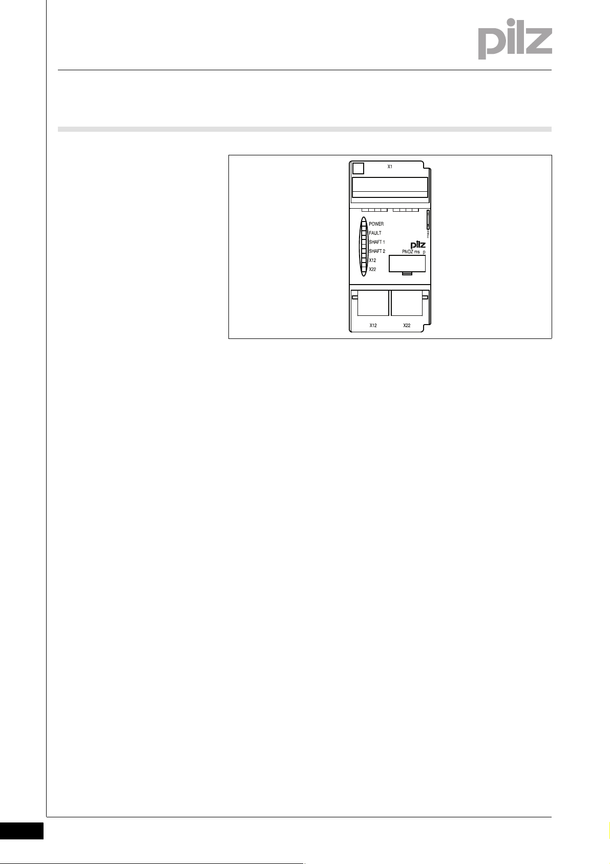
2.2 Front view
2.2Front view2200Front view2-Klemmenbelegung
Legende
Key:
X12:
– Female connector for connecting an incremental encoder to axis 1
X22:
– Female connector for connecting an incremental encoder to axis 2
LEDs:
–POWER
–FAULT
–SHAFT 1
–SHAFT 2
–X12
–X22
2-2
Pilz GmbH & Co. KG, Felix-Wankel-Straße 2, 73760 Ostfildern, Germany
Telephone: +49 711 3409-0, Telefax: +49 711 3409-133, E-Mail: pilz.gmbh@pilz.de
Page 11

3 Safety
3.1 Intended use
33000SafetySafety3-3.1Intended use3100Intended use3-Bestimmung/Gertebeschreibung_multi_Drehzahlwaechter
Bestimmung/Gertebeschreibung_multi_Zusatz_Modul
Bestimmung/Gertebeschreibung_multi_System
Bestimmung/Gertebeschreibung_multi_Drehzahlwchter_Warnungen_ms3_4p_BA
The expansion module monitors standstill, speed and direction of rotation in accordance with EN ISO 13849-1 up to PL e and EN IEC 62061
up to SIL CL 3.
The expansion module may only be connected to a base unit from the
configurable control system PNOZmulti (please refer to the document
"PNOZmulti System Expansion" for details of the base units that can be
connected)
The configurable control system PNOZmulti is used for the safety-related interruption of safety circuits and is designed for use in:
E-STOP equipment
Safety circuits in accordance with VDE 0113 Part 1 and EN 60204-1
WARNING!
Users must take appropriate measures to detect or exclude
errors (e.g. slippage or broken shearpin) which cause the frequency of the encoder signal to no longer be proportional to the
monitored speed.
Appropriate measures are:
Using the monitored encoder to also control the drive
Mechanical solutions
WARNING!
Encoder errors are detected and signalled via a diagnostic bit.
This does does not bring the relevant axis to a safe condition.
To maintain safety (Category 3), the diagnostic bit (diagnostic bit
10) in the user program must be evaluated in such a way that a
shutdown occurs if the axis is in operation (see examples in
Chapter 9).
Pilz GmbH & Co. KG, Felix-Wankel-Straße 2, 73760 Ostfildern, Germany
Telephone: +49 711 3409-0, Telefax: +49 711 3409-133, E-Mail: pilz.gmbh@pilz.de
3-1
Page 12

3 Safety
3.1 Intended use
3.1.1 System requirements
System requirements3-Systemvoraussetzungen - Verweis auf Produktänderungen
CAUTION!
If there are frequency differences between tracks A and B of the
incremental encoder, the track with the higher frequency will be
evaluated. Different directions of rotation will no longer be
detected. The outputs
to a safe condition. The safe condition is cleared again as soon
as the error is remedied. Hazards that can arise through an automatic restart must be excluded within the user program.
Please refer to the "Product Modifications" document in the "Version
overview" section for details of which versions of the base unit and
PNOZmulti Configurator can be used for this product.
Clockwise
and
Anti-clockwise
switch
3-2
Pilz GmbH & Co. KG, Felix-Wankel-Straße 2, 73760 Ostfildern, Germany
Telephone: +49 711 3409-0, Telefax: +49 711 3409-133, E-Mail: pilz.gmbh@pilz.de
Page 13

3 Safety
3.2 Safety regulations
3.2Safety regulations3200Safety regulat ions3-
3.2.1 Use of qualified personnel
Use of qualified personnel3-Sich Qualif. Personal
The products may only be assembled, installed, programmed, commissioned, operated, maintained and decommissioned by competent persons.
A competent person is someone who, because of their training, experience and current professional activity, has the specialist knowledge required to test, assess and operate the work equipment, devices,
systems, plant and machinery in accordance with the general standards
and guidelines for safety technology.
It is the company's responsibility only to employ personnel who:
Are familiar with the basic regulations concerning health and safety /
accident prevention
Have read and understood the safety guidelines given in this descrip-
tion
Have a good knowledge of the generic and specialist standards ap-
plicable to the specific application.
3.2.2 Warranty and liability
Warranty and liability3-Sich Gewhrleistung
3.2.3 Disposal
Disposal3-Si ch Entsorgung
All claims to warranty and liability will be rendered invalid if:
The product was used contrary to the purpose for which it is intended
Damage can be attributed to not having followed the guidelines in the
manual
Operating personnel are not suitably qualified
Any type of modification has been made (e.g. exchanging compo-
nents on the PCB boards, soldering work etc.).
In safety-related applications, please comply with the mission time t
M
in the safety-related characteristic data.
When decommissioning, please comply with local regulations regard-
ing the disposal of electronic devices (e.g. Electrical and Electronic
Equipment Act).
Pilz GmbH & Co. KG, Felix-Wankel-Straße 2, 73760 Ostfildern, Germany
Telephone: +49 711 3409-0, Telefax: +49 711 3409-133, E-Mail: pilz.gmbh@pilz.de
3-3
Page 14

3 Safety
3.2 Safety regulations
3.2.4 For your safety
For your safety3-Zu Ihrer Sicherheit_multi_Module
The unit meets all necessary conditions for safe operation. However,
you should always ensure that the following safety requirements are
met:
This operating manual only describes the basic functions of the unit.
Information on the advanced functions can be found in the online help
for the PNOZmulti Configurator and in the PNOZmulti technical catalogue. Only use these functions after you have read and understood
the documentation. All necessary documentation can be found on the
PNOZmulti Configurator CD.
Do not open the housing or make any unauthorised modifications.
Please make sure you shut down the supply voltage when performing
maintenance work (e.g. exchanging contactors).
3-4
Pilz GmbH & Co. KG, Felix-Wankel-Straße 2, 73760 Ostfildern, Germany
Telephone: +49 711 3409-0, Telefax: +49 711 3409-133, E-Mail: pilz.gmbh@pilz.de
Page 15

4 Function description
Interface
to previous
module
Interface
to next
module
X12 X22
X1
4.1 Unit properties
44000Function descriptionFunction description4-4.1Unit properties4100Unit properties4-
4.1.1 Integrated protection mechanisms
Integrated protection mechanisms4-Sicherheitseigenschaften_multi_allgemein
The relay conforms to the following safety criteria:
The circuit is redundant with built-in self-monitoring.
The safety function remains effective in the case of a component fail-
ure.
4.1.2 Function description
Function description4-
4.1.2.1 Operation
Operation4-Funktionen_multi_Drehzahlwächter_nur_Inkrementalgeber_2Achsen
The speed monitor can independently monitor two axes for standstill,
speed and direction of rotation. The speed monitor signals the status of
the monitored values to the base unit. Depending on the implemented
safety circuit, the values may be transferred from the base unit to a relay
output on the safety system, for example. Incremental encoders may be
used to record the values.
4.1.2.2 Block diagram
Block diagram4-Blockschaltbild
The configuration of the speed monitor is described in detail in the
PNOZmulti Configurator's online help.
Pilz GmbH & Co. KG, Felix-Wankel-Straße 2, 73760 Ostfildern, Germany
Telephone: +49 711 3409-0, Telefax: +49 711 3409-133, E-Mail: pilz.gmbh@pilz.de
4-1
Page 16

4 Function description
4.2 Input device types
4.2Input device types4200Input device types4-
4.2.1 Incremental encoders
Incremental encoders4-
4.2.1.1 Requirements of the incremental encoders
Requirements of the incremental encoders4-Drehzahlwaechter_Inkrementalgebertypen_sin/cos_TTL
4.2.1.2 Adapter for incremental encoders
Adapter for incremental encoders4-Drehzahlwaechter_Inkrementalgeber_Adapter
Only incremental encoders with a differential output of the following
type are permitted
– Sin/Cos
– TTL (RS 422)
Pay attention to the values in the technical details
The adapter records the data between the incremental encoder and the
drive and makes it available to the speed monitor via the RJ45 socket.
Pilz supplies complete adapters as well as ready-made cable with RJ45
connector, which can be used when making your own adapter. The
range of products in this area is constantly being expanded. Please contact us about the range of adapters that is currently available.
4-2
Pilz GmbH & Co. KG, Felix-Wankel-Straße 2, 73760 Ostfildern, Germany
Telephone: +49 711 3409-0, Telefax: +49 711 3409-133, E-Mail: pilz.gmbh@pilz.de
Page 17

5 Installation
5.1 General installation guidelines
55000InstallationInstallation5-5.1General installation guidelines5100General installation guidelines5-Montage_multi_allgemein
Montage_multi_Bild_BA
The control system should be installed in a control cabinet with a pro-
tection type of at least IP54. Fit the control system to a horizontal
mounting rail. The venting slots must face upward and downward.
Other mounting positions could destroy the control system.
Use the notches on the rear of the unit to attach it to a mounting rail.
Connect the control system to the mounting rail in an upright position,
so that the earthing springs on the control system are pressed on to
the mounting rail.
The ambient temperature of the PNOZmulti units in the control cabi-
net must not exceed the figure stated in the technical details, otherwise air conditioning will be required.
To comply with EMC requirements, the mounting rail must have a low
impedance connection to the control cabinet housing.
Montage_EMV ESD
CAUTION!
Damage due to electrostatic discharge!
Electrostatic discharge can damage components. Ensure
against discharge before touching the product, e.g. by touching
an earthed, conductive surface or by wearing an earthed armband.
Pilz GmbH & Co. KG, Felix-Wankel-Straße 2, 73760 Ostfildern, Germany
Telephone: +49 711 3409-0, Telefax: +49 711 3409-133, E-Mail: pilz.gmbh@pilz.de
5-1
Page 18

5 Installation
94 (3.70")
45
(1.77")
121 (4.76")
5.1 General installation guidelines
5.1.1 Dimensions
Dimensions5-Abmessungen
5-2
Pilz GmbH & Co. KG, Felix-Wankel-Straße 2, 73760 Ostfildern, Germany
Telephone: +49 711 3409-0, Telefax: +49 711 3409-133, E-Mail: pilz.gmbh@pilz.de
Page 19

5 Installation
Base unit
Expansion module 1 Expansion module 8
774639: Jumper 779110: Terminator
Speed monitor
max. 4 Speed monitors
5.2 Connecting the base unit and expansion modules
5.2Connecting the base unit and expansion modules5200Connecting the base unit and expansion modules5-Montage_multi_Modul_verbind_rechts_BA
Connect the base unit and the expansion modules as described in the
operating manuals for the base modules.
The terminator must be fitted to the last expansion module
Install the expansion module in the position configured in the PNOZ-
Montage_multi_Anzahl_Module_Drehzahlwaechter_BA
Montage
multi Configurator.
You can install a maximum of 4 speed monitors to the right of the base
unit.
Pilz GmbH & Co. KG, Felix-Wankel-Straße 2, 73760 Ostfildern, Germany
Telephone: +49 711 3409-0, Telefax: +49 711 3409-133, E-Mail: pilz.gmbh@pilz.de
5-3
Page 20

5 Installation
5-4
Pilz GmbH & Co. KG, Felix-Wankel-Straße 2, 73760 Ostfildern, Germany
Telephone: +49 711 3409-0, Telefax: +49 711 3409-133, E-Mail: pilz.gmbh@pilz.de
Page 21

6 Commissioning
6.1 General wiring guidelines
66000CommissioningCommissioning6-6.1Gene ral wiring guideline s6100General wi ring guidelines6-Verdrahtung_multi_Drehzahlwaechter
The wiring is defined in the circuit diagram of the PNOZmulti Configurator.
Details of the input type, axis type and reset mode, plus the values for
standstill, speed monitoring and direction of rotation are also defined in
the PNOZmulti Configurator.
Please note:
Information given in the "Technical details" must be followed.
Verdrahtung
Use copper wire that can withstand 75 °C.
CAUTION!
The configurable switch-off delay when overspeed is reached
increases the reaction time of the system comprising base unit
and speed monitor by the stated value (see technical details).
This must not delay the transfer to a safe condition by more than
the permitted time. The configuration of the switch-off delay
must be considered in the risk assessment as regards hazards,
reaction time and safety distance.
Pilz GmbH & Co. KG, Felix-Wankel-Straße 2, 73760 Ostfildern, Germany
Telephone: +49 711 3409-0, Telefax: +49 711 3409-133, E-Mail: pilz.gmbh@pilz.de
6-1
Page 22

6 Commissioning
X12
X22
Speed monitor
5 V DC
0 V
2
4
5
7
8
A
/A
B
/B
5 V
0 V
Z
o
Z
o
Incremental
encoder
6.2 Preparing for operation
6.2Preparing for operation6200Preparing for operation6-
6.2.1 Connecting the incremental encoder
Connecting the incremental encoder6-Drehzahlwaechter_Betriebsb_Inkremen
Follow the instructions below when connecting the incremental encoder:
The incremental encoder can be connected via an adapter (e.g. PNOZ
msi4p) or can be connected directly to the speed monitor.
The incremental encoder on connector X12 monitors axis 1; the incre-
mental encoder on connector X22 monitors axis 2.
Only use shielded cables for all connections
Always connect 0 V on the incremental encoder and speed monitor.
Position the terminating resistors on the signal lines as close as pos-
sible to the input on the speed monitor.
6.2.1.1 Connect the signals from the incremental encoder to the speed monitor
Connect the signals from the incremental encoder to the speed monitor 6-Drehzahlwaechter_Betriebsb_Inkremen_5V-TTL_ms3p_BA
Encoder types: 1 Vss, 5 V-TTL
Apply 5 VDC to incremental encoder only
Do not terminate incremental encoder with Z
=120 Ohm
0
Fig. 6-1: Connection to incremental encoder type 1 Vss, 5 V-TTL
6-2
Pilz GmbH & Co. KG, Felix-Wankel-Straße 2, 73760 Ostfildern, Germany
Telephone: +49 711 3409-0, Telefax: +49 711 3409-133, E-Mail: pilz.gmbh@pilz.de
Page 23

6 Commissioning
Incremental
encoder
A
/A
B
/B
Z
o
Z
o
X12
X22
Speed monitor
Drive
Adapter
5 V
0 V
5 V DC
0 V
18
6.2 Preparing for operation
6.2.1.2 Connect the incremental encoder to the speed monitor via an adapter
Connect the incremental encoder to the speed monitor via an adapter 6-Drehzahlwaechter_Betriebsb_Inkremen_ueber_Adapt_ohne_24 V HTL_ms2p_BA
The adapter (e.g. PNOZ msi6p) is connected between the incremental
encoder and the drive. The output on the adapter is connected to the
RJ-45 female connector on the speed monitor.
The adapter also can be used without connecting to a drive. The sig-
nal lines can then be terminated directly at the adapter with Z
= 120
O
Ohm.
If the signal lines in the drive are already terminated with Z
=
O
120 Ohm, the incremental encoder may no longer be terminated.
The signals relevant for the speed monitor are utilised in parallel by
the adapter. The information stated in section 6.2.2.1 and in the
adapter operating manual must be observed when connecting the
supply voltage.
Supply 5 VDC to incremental encoder only.
Fig. 6-2: Connection via adapter and drive
Pilz GmbH & Co. KG, Felix-Wankel-Straße 2, 73760 Ostfildern, Germany
Telephone: +49 711 3409-0, Telefax: +49 711 3409-133, E-Mail: pilz.gmbh@pilz.de
6-3
Page 24

6 Commissioning
Incremental
encoder
A
/A
B
/B
Z
o
Z
o
X12
X22
Speed monitor
Adapter
5 V
0 V
5 V DC
0 V
1
8
6.2 Preparing for operation
Fig. 6-3: Connection via adapter
6-4
Pilz GmbH & Co. KG, Felix-Wankel-Straße 2, 73760 Ostfildern, Germany
Telephone: +49 711 3409-0, Telefax: +49 711 3409-133, E-Mail: pilz.gmbh@pilz.de
Page 25

7 Operation
7.1 Messages
77000OperationOperation7-7.1Messages71 00Messages7-Betrieb_Meldungen_allgemein_BA
Betrieb_Meldungen_Modul _Ready_BA
When the supply voltage is switched on, the PNOZmulti safety system
copies the configuration from the chip card.
The LEDs "POWER","DIAG", "FAULT", "IFAULT" and "OFAULT" light up
on the base unit.
The PNOZmulti safety system is ready for operation when the "POWER"
and "RUN" LEDs on the base unit and the "READY" LED on the PNOZ
ms3p TTL are lit continuously.
Pilz GmbH & Co. KG, Felix-Wankel-Straße 2, 73760 Ostfildern, Germany
Telephone: +49 711 3409-0, Telefax: +49 711 3409-133, E-Mail: pilz.gmbh@pilz.de
7-1
Page 26

7 Operation
7.2 Display elements
7.2Display elements7200Display elements7-Anzeige Legende 3x
Legend:
LED on
LED flashes
LED off
7.2.1 Display elements for unit diagnostics
Display elements for unit diagnostics7-Betrie b
LED LED status Key
POWER Supply voltage is present
FAULT External fault leading to a safe condition; the fault is at the incremental encoder in-
puts whose LEDs are flashing, e.g. short across the contacts
Internal fault leading to safe condition
SHAFT1
SHAFT2
X12
X22
Input device or wiring fault
Axis 1 and/or axis 2 are in the normal range (no standstill, no overspeed)
Axis 1 and/or axis2 is signalling standstill
Axis 1 and/or axis2 is signalling overspeed
Incremental encoders on terminals X12 and/or X22 are connected correctly
7-2
Pilz GmbH & Co. KG, Felix-Wankel-Straße 2, 73760 Ostfildern, Germany
Telephone: +49 711 3409-0, Telefax: +49 711 3409-133, E-Mail: pilz.gmbh@pilz.de
Page 27

8 Technical details
8.1 Technical details
88000Technical detailsTechnical details8-8.1Technical details8100Technical details8-][Technische Daten_multi_Drehzahlwaechter_ms3-ms4
Technical details
Electrical data
Supply voltage UB DC
Via base unit 5 V
Voltage tolerance -15 %/+20 %
Power consumption at U
Via base unit 1.0 W
Residual ripple DC 5 %
Status display LED
Times
Configurable switch-off delay 0 - 2,500 ms
Reaction time
f>100 Hz: configurable switch-off delay + switch-off delay
on base unit *
f<100 Hz: configurable switch-off delay + switch-off delay
on base unit *
Supply interruption before de-energisation 20 ms
Incremental encoder input
Number of inputs 2
Input signal level 0.5 - 5.0 Vss
Phase position for the differential signals A,/A and B,/B 90° ±30°
Overload protection -30 - 30 V
Input resistance 10.0 kOhm
Input's frequency range 0 - 500 kHz
Configurable monitoring frequency
without hysteresis 0,1 Hz - 500 kHz
with hysteresis 0,2 Hz - 500 kHz
Connection type (incremental encoder) RJ45 socket, 8-pin
Environmental data
EMC EN 60947-5-1
Vibration to EN 60068-2-6
Frequency 10 - 55 Hz
Amplitude 0.35 mm
Climatic suitability EN 60068-2-78
Airgap creepage in accordance with EN 60664-1
Ambient temperature 0 - 60 °C
Storage temperature -25 - 70 °C
Mechanical data
Protection type
Mounting (e.g. cabinet) IP54
Housing IP20
Terminals IP20
DIN rail
Top hat rail 35 x 7.5 EN 50022
Recess width 27 mm
Housing material
Housing PPO UL 94 V0
Front ABS UL 94 V0
Torque setting with screw terminals 0.25 Nm
DC
B
10 ms
10 ms + 1/f
Pilz GmbH & Co. KG, Felix-Wankel-Straße 2, 73760 Ostfildern, Germany
Telephone: +49 711 3409-0, Telefax: +49 711 3409-133, E-Mail: pilz.gmbh@pilz.de
8-1
Page 28

8 Technical details
8.1 Technical details
Mechanical data
Dimensions
Height 94.0 mm
Width 45.0 mm
Depth 121.0 mm
Weight 220 g
Si-Kennzahlen_alle
Safety characteristic data
Unit Operating mode EN ISO 13849-
1: 2006
EN 954-1
Category
EN IEC 62061
SIL CL
PFH [1/h] EN ISO
PL
incremental encoder PL e (Cat. 3) Cat. 3 SIL CL 3 6.36E-09 20
Si_Kennzahlen_Erläuterung_1
All the units used within a safety function must be considered when calculating the safety characteristic data.
Technische Daten_Satz No rmen
The standards current on 2009-10 apply.
13849-1:
2006
[year]
T
M
8-2
Pilz GmbH & Co. KG, Felix-Wankel-Straße 2, 73760 Ostfildern, Germany
Telephone: +49 711 3409-0, Telefax: +49 711 3409-133, E-Mail: pilz.gmbh@pilz.de
Page 29

8 Technical details
8.2 Order reference
8.2Order reference8200Order reference8-Bestelldaten PNOZ ms3p TTL
Order reference
Product type Features Order no.
PNOZ ms3p TTL Expansion module, speed monitor 773 826
Bestelldaten Zubehör PNOZ ms1/2/3/4p
Order reference: Accessories
Product type Features Order no.
Set spring terminals 1 set of spring-loaded terminals 783 800
Set screw terminals 1 set of screw terminals 793 800
Bestelldaten Zubehör Abschlussstecker/Steckbrücke
Order reference: Terminator, jumper
Product type Features Order no.
PNOZmulti bus terminator Terminator 779 110
KOP-XE Jumper 774 639
Pilz GmbH & Co. KG, Felix-Wankel-Straße 2, 73760 Ostfildern, Germany
Telephone: +49 711 3409-0, Telefax: +49 711 3409-133, E-Mail: pilz.gmbh@pilz.de
8-3
Page 30

8 Technical details
8-4
Pilz GmbH & Co. KG, Felix-Wankel-Straße 2, 73760 Ostfildern, Germany
Telephone: +49 711 3409-0, Telefax: +49 711 3409-133, E-Mail: pilz.gmbh@pilz.de
Page 31

9 Application examples
9.1 Examples without position control
99000Application examplesApplication examples9-9.1Exampl es without positio n control9100Exam ples without posi tion control9-Applikationsbe ispiel_ohne_Lagereg elung_PNOZms3_ein leitung_Bit10_BA
Evaluation of bit: "Unfeasible or single-channel signal from the
incremental encoder", without position control
Diagnosticbit 10: "Unfeasible or single-channel signal from the incremental encoder" must be evaluated in the user program during operation in such a way that a set bit leads to a safety-related error reaction
(shutdown).
9.1.1 Example 1
Example 19-Applikationsbeispiel_ohne_Lageregelung_1_PNOZms3_sofort_absch_BA
Immediate shutdown as soon as diagnostic bit 10 is set.
The bit is evaluated as follows:
The connection point "Input Device OK" must be incorporated into the
application and evaluated in such a way that a shutdown occurs if the
connection point "Input Device OK"= 0.
Pilz GmbH & Co. KG, Felix-Wankel-Straße 2, 73760 Ostfildern, Germany
Telephone: +49 711 3409-0, Telefax: +49 711 3409-133, E-Mail: pilz.gmbh@pilz.de
9-1
Page 32

9 Application examples
9.1 Examples without position control
9.1.2 Example 2
Example 29-Applikationsbeispiel_ohne_Lageregelung_2_PNOZms3_verzögerte absch_BA
A set diagnostic bit 10 can be tolerated for a maximum of 4 hours (occurrence of second error). If no feasible signals above standstill frequency are measured within this time, a shutdown will occur.
In this case, the bit will be evaluated as follows:
9-2
Please note that the direction of rotation must be evaluated for this example!
Pilz GmbH & Co. KG, Felix-Wankel-Straße 2, 73760 Ostfildern, Germany
Telephone: +49 711 3409-0, Telefax: +49 711 3409-133, E-Mail: pilz.gmbh@pilz.de
Page 33

9 Application examples
PNOZmulti Base Unit
PNOZ
ms3p
ms4p
PLC
Drive Control
M
Enable
Position Control
9.2 Example with position control
9.2Example with position control 9200Exam ple with position control 9-Applikationsbeispiel_DZW_mit_Lageregelung_PNOZms3_4p_BA
Evaluation of bit: "Unfeasible or single-channel signal from the
incremental encoder", with position control
Diagnostic bit 10: "Unfeasible or single-channel signal from the incremental encoder" may be set during position control as a result of jitter
on the encoder.
The set bit can be tolerated, i.e. evaluated in the user program in such a
way that a shutdown will not occur if the following conditions are met:
An additional position control signal must be provided from an exter-
nal control system (e.g. PLC) and
The signal must have the following status conditions:
– Position control: Signal status = 1
– Operation: Signal status = 0
During operation, diagnostic bit 10 must be evaluated in the user program in such a way that a set bit leads to a safety-related error reaction
(shutdown).
Application example:
Pilz GmbH & Co. KG, Felix-Wankel-Straße 2, 73760 Ostfildern, Germany
Telephone: +49 711 3409-0, Telefax: +49 711 3409-133, E-Mail: pilz.gmbh@pilz.de
9-3
Page 34

9 Application examples
9.2 Example with position control
Depending on the operating mode, evaluation of diagnostic bit 10 can
be implemented in the user program as follows
9-4
An additional "Position Control" signal is incorporated. This signal indicates whether the relevant axis is in position control (signal status = 1)
or in operation (signal status = 0).
The time element with configured switch-off delay operates as a startup suppressor, as the bit: "Unfeasible or single-channel signal from the
incremental encoder" may still be present for 2 s after leaving standstill.
The connection point "Input Device OK" must be incorporated into the
application and evaluated in such a way that a shutdown occurs if the
connection point "Input Device OK"= 0.
Pilz GmbH & Co. KG, Felix-Wankel-Straße 2, 73760 Ostfildern, Germany
Telephone: +49 711 3409-0, Telefax: +49 711 3409-133, E-Mail: pilz.gmbh@pilz.de
Page 35

...
1001723-EN-02, 2011-11 Printed in Germany
© Pilz GmbH & Co. KG, 2011
+49 711 3409-444
support@pilz.com
Pilz GmbH & Co. KG
Felix-Wankel-Straße 2
73760 Ostfildern, Germany
Telephone: +49 711 3409-0
Telefax: +49 711 3409-133
E-Mail: pilz.gmbh@pilz.de
Internet: www.pilz.com
Technical support
In many countries we are
represented by our subsidiaries
and sales partners.
Please refer to our homepage
for further details or contact our
headquarters.
InduraNET p
®
, Pilz
®
, PIT
®
, PMCprotego
®
, PMI
®
, PNOZ
®
, Primo
®
, PSEN
®
, PSS
®
, PVIS
®
, SafetyBUS p
®
, SafetyEYE
®
, SafetyNET p
®
, the spirit of safety
®
are registered and protected trademarks
of Pilz GmbH & Co. KG in some countries. We would point out that product features may vary from the details stated in this document, depending on the status at the time of publication and the scope
of the equipment. We accept no responsibility for the validity, accuracy and entirety of the text and graphics presented in this information. Please contact our Technical Support if you have any questions.
Contact address
 Loading...