


Philips FR975, FR975/00, FR975/17, FR975/01C, MX980D/37 Service Manual
DIGITALE A/V SURROUND RECEIVER
07/08/2012
World of Free Manuals
FR975
/00/01C/17
MX980D/37
Service Manual
DOLBY
D I G I T A L
TABLE OF CONTENTS
Page
Location Boards / System info ................................................... 1-2
Technical Specification ............................................................. 1-3
Service Tool / Measurement setup / Safety .............................. 1-4
Warning / Handling Chip components ...................................... 1-5
Abbreviations ............................................................................ 1-6
Instruction for Use ...................................................................... 2
Dismantling hints / Service positions ......................................... 3-1
Dismantling hints MDM Module ................................................ 3-2
Wiring diagram .......................................................................... 3-3
Block diagram ............................................................................ 4
Service Test program ................................................................. 5
Front Board ............................................................................... 6
Tuner 95 diagram ...................................................................... 7A
ECO 5 Tuner diagram ............................................................... 7B
Multi-Channel Decoding Module ................................................ 8
Mains Board .............................................................................. 9
Mono Board ............................................................................... 10
Exploded view ........................................................................... 11
S-VHS Board .............................................................................. 12
Exploded view partslist .............................................................. 13
Partslist Mono Board ................................................................ 1 4
Safety regulations require that the set be restored to its original
condition and that parts which are indentical with those specified
be used.
Copyright 1995 Philips Consumer Electronics B.V. Eindhoven, The Netherlands
All rights reserved. No part of this publication may be reproduced, stored in a retrieval
system or transmitted, in any form or by any means, electronic, mechanical, photocopying,
or otherwise without the prior permission of Philips.
Published by MD 0016 Service Audio Printed in the Netherlands Subject to modification
PCS 102 481
3104 215 50060

LOCATION OF PRINTED CIRCUIT BOARDS
07/08/2012
World of Free Manuals
Screw Terminal
Mains Board
P50 & Subw. &
Video Selector
Board
Secondary
Trafo Board
1-2
Tuner Board
MDM Board
S-VHS
Video Board
Mono 2 Board
Headphone & Front AV
Board
SYSTEM INFORMATION
Receiver
MX 980D/37 include :
FR975/17
Front speaker
2 x Home Cinema
Speaker 100W
VERSION VARIATIONS
Type &
Features &
Board in used
Front colour
Tuner board - Tuner 95
Tuner board - ECO 5
RDS
Antenna input FM
Mains cord type
Mains outlet type
Mains voltage
Voltage selector
Versions
Front Board
Center speaker Surround speaker
Home Cinema Center
Speaker 100W
2 x Home Cinema
Speaker 100W
FR975
/00
Black
x
x
Coaxial 75R
IEC
IEC
230V
-
/01C
Champagne
x
Coaxial 75R
IEC
IEC
110-127 / 220-240
x
Subwoofer
FB201V/17
/17
Black
x
Clickfit 300R
UL polarized
UL polarized
120V
-
PCS 102 482

SPECIFICATION FR975
07/08/2012
World of Free Manuals
1-3
General
Mains voltage :230V for /00
:110-127V / 220-240
switchable only /01/01C
: 120V for /17
Mains frequency : 50Hz for /00
: 50/60Hz for /01/01C
: 60Hz for /17
Power concumption : ≤ 2W at stby
: ≤ 3W at stby 240V/01/01C
Dimension. wxhxd : 435x138x350 mm
Remote control : Multibrand/Universal
Amplifier
Output power
Stereo mode (L+R) : 2x100W DIN only /00/01
(1kHz,0,7%THD, 6Ω)
: 2x80W FTC only /17
(40Hz-20kHz 0,7%THD, 6Ω)
Surround mode
L+R : 2x100W (1kHz,0,7%THD, 6Ω)
Center : 100W (1kHz,0,7%THD, 6Ω)
Surround Left+Right : 2x100W (1kHz,0,7%THD, 6Ω)
Distortion (5W)
1kHz : ≤ 0,05%
40Hz - 20kHz : ≤ 0,2%
Headphone : 6,3mm stereo jack with switch
Output level : 3V EMF, 60Ω
Crosstalk between source —1kHz : ≤ -65dB
(1W) 250Hz – 10kHz : ≤ -60dB
Crosstalk between channels -1kHz : ≤ -55dB
(1W) 250Hz – 10kHz : ≤ -50dB
Frequency response
: ≤ 10Hz – ≥ 20kHz (-3dB) Limit
Power stage protection : Shortcircuit
: DC (Vout ≥ 10V) for ±1sec
Temperature : Transformer ( ≥140º Celcius)
: Heatsink ( ≥ 140º Celcius)
Audio Selector
Input sensitivity
Phono : 5mV impedance 47kΩ/220pf
CD : 250mV impedance ≥ 47kΩ
CDR/TAPE : 250mV impedance ≥ 47kΩ
VCR : 250mV impedance ≥ 47kΩ
TV : 250mV impedance ≥ 47kΩ
SAT : 250mV impedance ≥ 47kΩ
6CH / DVD : 250mV impedance ≥ 47kΩ
FRONT AV : 250mV impedance ≥ 22kΩ
Output level
CDR/TAPE : 250mV impedance ≤ 1kΩ
VCR : 250mV impedance ≤ 1kΩ
Output level (variable)
Subwoofer pre-out : 800mV impedance ≤ 1kΩ
Center pre-out : 800mV impedance ≤ 1kΩ
Digital Selector
Input : 2 x cinch
: 2 x optical
Output : 1 x cinch
Video Selector - CVBS
Input sensitivity
DVD/VCR/TV/Front AV : 1 Vpp impedance 75Ω
Output level
Monitor/VCR : 1 Vpp impedance 75Ω
Frequency response : ≤ 50Hz à ≥ 6MHz
Video Selector - SVHS
Input sensitivity
DVD/VCR/TV : 1 Vpp impedance 75Ω
Output level
Monitor/VCR : 1 Vpp impedance 75Ω
Frequency response : ≤ 50Hz à ≥ 6MHz
Tone controle
Loudness
(volume ≤ -20dB Ref: 1kHz=0dB) : 100Hz +6 dB
: 10kHz +2,5 dB
Tone control (Ref: 1kHz=0dB)
: Bass 100Hz -9dB à+9dB
: Treble 10kHz -9dB à+9dB
Multi Channel Decoder - MDM2000
MPEG5.1 / MPEG 7.1 (7.1 downmix to 5.1)
Dolby Digital (AC-3)
Digital Theater Systems (DTS)
Linear PCM (up to 96kHz, 24 bits resolution)
Automatic audio/data type detection (AC-3,dts,MPEG-2,PCM)
Dolby Pro Logic
MPEG-2 dual mono channel selection I/II
Virtual Dolby Surround (422/423)
Virtual MPEG Digital (522/523)
Virtual Dolby Digital (522/523)
Virtual DTS Surround (522/523)
Multi - Front / Multi - rear / Natural Surround
Digital Bass Management
Parallel Stereo Downmix
Four Stereo (224)
Volume Control
Noise Generator (test tone)
Surround mode selector
Delay Center and Surround Left , Surround Right
Tuner - (Tuner95 & ECO5)
RDS : Only in /00
FM
Tuning range : 87.5 – 108MHz
Grid : 50kHz
: 100kHz only for /17
: 50 & 100kHz for /01/01C*
IF frequency : 10.7MHz ±25kHz
Aerial input : 75 Ω coaxial
: 300 Ω clickfit only for /17
Sensitivity at 26dB S/N : ≤ 2µv
Selectivity at 300kHz : ≥ 55dB
Image rejection : ≥ 100dB [48dB]
Distortion at RF=1mV,dev.75kHz : ≤ 0,8% [0,9%]
-3dB Limiting point : ≤ 2µV
Crosstalk at RF=1mV,dev.40kHz : ≥ 35dB [27dB]
: ≥ 22dB only for /17
MW
Tuning range : 522 -1611kHz for /00
: 531 -1602kHz for/01/01C*
: 530 -1700kHz for/01/01C*
: 530 -1700kHz for /17
Grid : 9kHz for /00
: 9 & 10kHz for /01/01C*
: 10kHz for /17
IF frequency : 450kHz ±1kHz
Aerial input : Frame aerial
Sensitivity at 26dB S/N : ≤ 1,5mV/m [3,5mV/m]
Selectivity at 9kHz : ≥ 23dB [18dB]
IF rejection : ≥ 50dB [64dB]
Image rejection : ≥ 33dB [28dB]
Distortion at RF=50mV,m=80% : ≤ 3%
LW only in /00
Tuning range : 153 - 279kHz
Grid : 3kHz
IF frequency : 450kHz ±1kHz
Aerial input : Frame aerial
Sensitivity at 26dB S/N : ≤ 2,8mV/m
Selectivity at 9kHz : ≥ 26dB
: ≥ 24dB only for /17
IF rejection : ≥ 100dB
Image rejection : ≥ 45dB
Distortion at RF=50mV,m=80% : ≤ 3%dB
[…] Values indicated are for “ECO 5 Tuner” only
* Setting is software controlled
PCS 102 483
1-4
07/08/2012
World of Free Manuals
SERVICE TOOL
Audio Signals Test Disc 1 ................................. 4822 397 30184
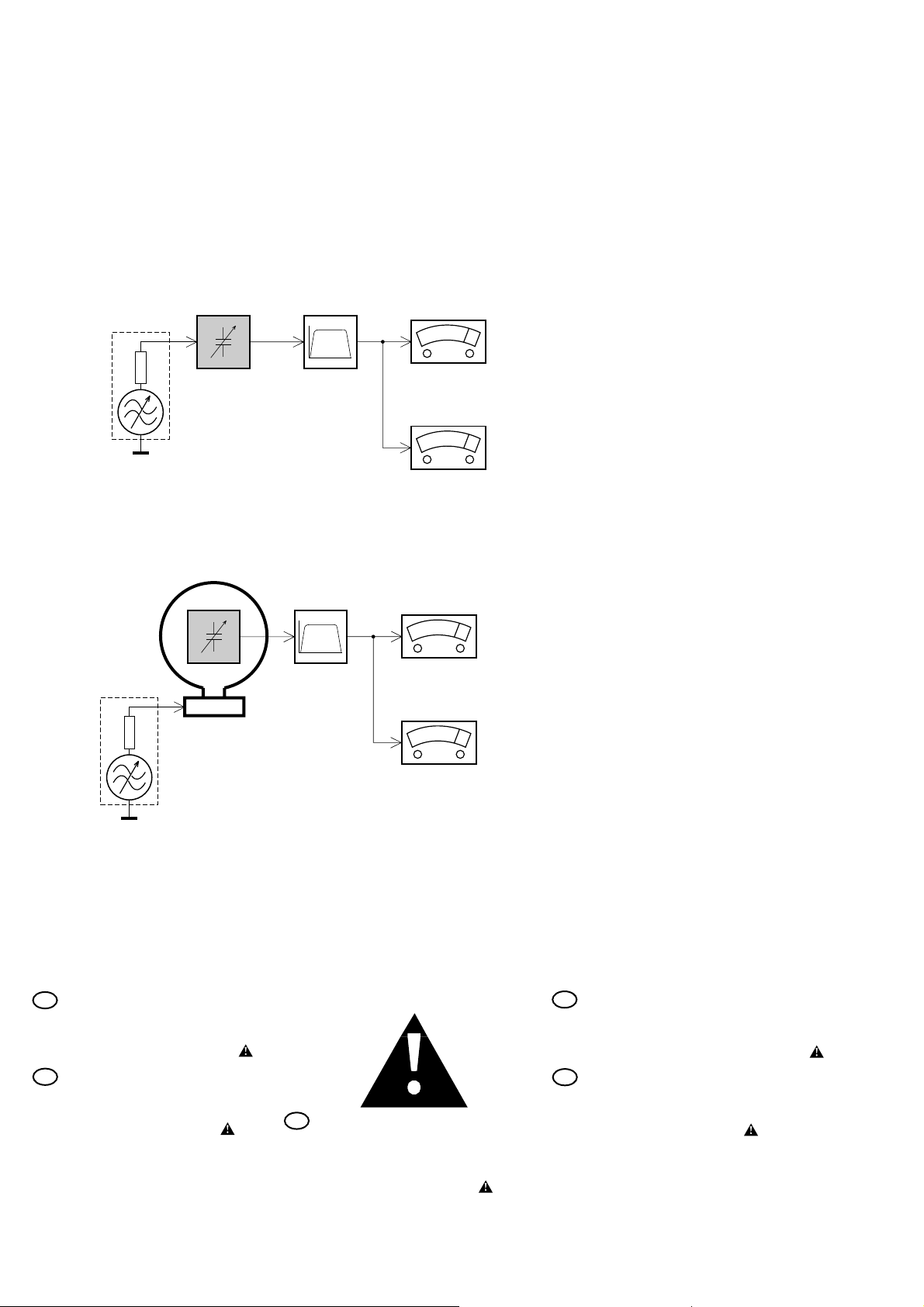
MEASUREMENT SETUP
Tuner FM
Bandpass
LF Voltmeter
e.g. PM2534
RF Generator
e.g. PM5326
DUT
250Hz-15kHz
e.g. 7122 707 48001
Ri=50Ω
S/N and distortion meter
e.g. Sound Technology ST1700B
Use a bandpass filter to eliminate hum (50Hz, 100Hz) and disturbance from the pilottone (19kHz, 38kHz).
Tuner AM (MW,LW)
RF Generator
e.g. PM5326
Ri=50Ω
DUT
Frame aerial
e.g. 7122 707 89001
Bandpass
250Hz-15kHz
e.g. 7122 707 48001
LF Voltmeter
e.g. PM2534
S/N and distortion meter
e.g. Sound Technology ST1700B
To avoid atmospheric interference all AM-measurements have to be carried out in a Faraday´s cage.
Use a bandpass filter (or at least a high pass filter with 250Hz) to eliminate hum (50Hz, 100Hz).
SAFETY
GB
Safety regulations require that the set be restored to its
original condition and that parts which are identical with
those specified be used.
Safety components are marked by the symbol
F
Les normes de sécurité exigent que l`appareil soit remis
à l`état d`origine et que soient utilisées les pièces de
rechange identiques à celles spécifiées.
Les composants de sécurité sont marqués
PCS 102 484
D
Bei jeder Reparatur sind die geltenden Sicherheitsvorschriften zu beachten. Der Originalzustand des Gerätes
darf nicht verändert werden. Für Reparaturen sind Originalersatzteile zu verwenden.
Sicherheitsbauteile sind durch das Symbol markiert.
SAFETY
NL
Veiligheidsbepalingen vereisen, dat het apparaat in zijn
oorspronkeliijke toestand wordt teruggebracht en dat
onderdelen, identiek aan de gespecificeerde, worden toegepast.
De Veiligheidsonderdelen zijn aangeduid met het symbool
I
Le norme di sicurezza estigono che l´apparecchio venga
rimesso nelle condizioni originali e che siano utilizzati i
pezzi di ricambiago identici a quelli specificati.
Componenty di sicurezza sono marcati con
WARNING
07/08/2012
World of Free Manuals
1-5
GB WARNING
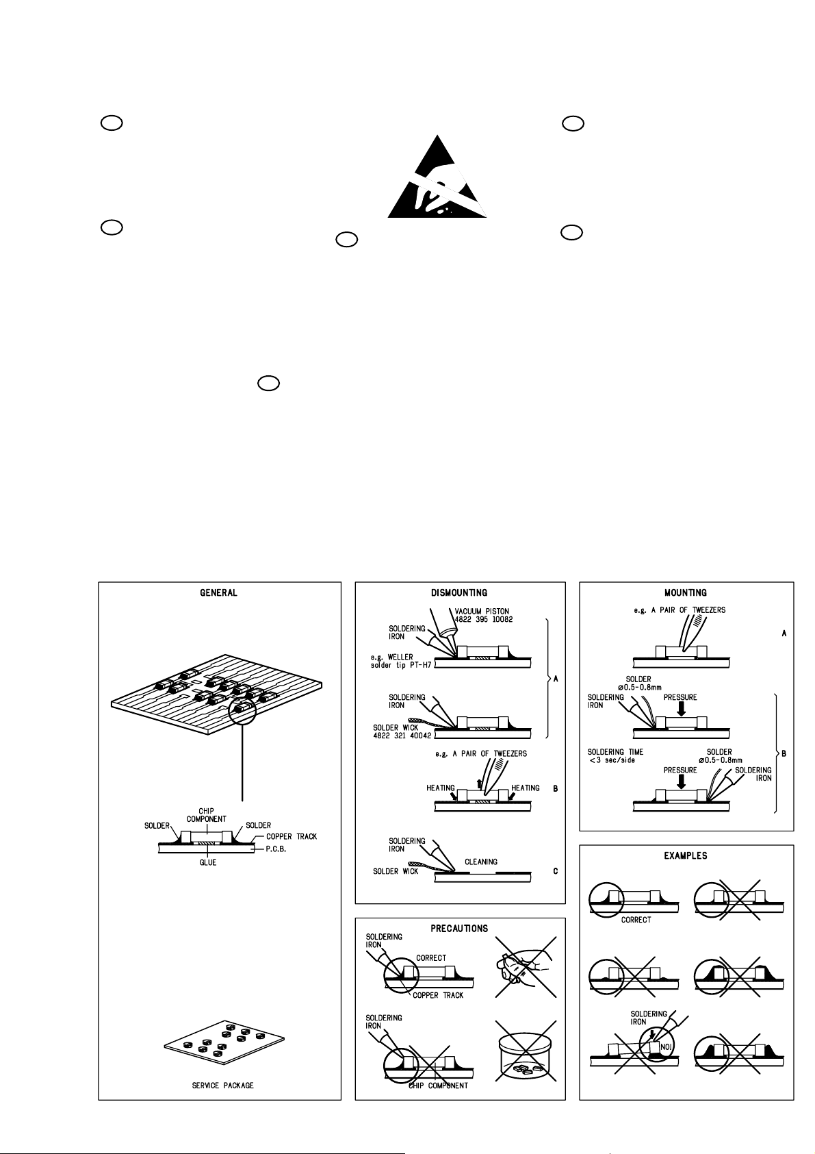
All ICs and many other semiconductors are susceptible to
electrostatic discharges (ESD). Careless handling during
repair can reduce life drastically.
When repairing, make sure that you are connected with the
same potential as the mass of the set via a wristband with
resistance. Keep components and tools at this potential.
F ATTENTION
Tous les IC et beaucoup d´autres semi-conducteurs sont
sensibles aux décharges statiques (ESD). Leur longévite
pourrait être considérablement écourtée par le fait qu´aucune
précaution nést prise à leur manipulation.
Lors de réparations, s´assurer de bien être relié au même
potentiel que la masse de l´appareil et enfileer le bracelet
serti d´une résistance de sécurité.
Veiller à ce que les composants ainsi que les outils que l´on
utilise soient également à ce potentiel.
GB
AVAILABLE ESD PROTECTION EQUIPMENT :
anti-static table mat large 1200x650x1.25mm 4822 466 10953
anti-static wristband 4822 395 10223
connection box (3 press stud connections, 1M ) 4822 320 11307
extendible cable (2m, 2M , to connect wristband to connection box) 4822 320 11305
connecting cable (3m, 2M , to connect table mat to connection box) 4822 320 11306
earth cable (1M , to connect any product to mat or to connection box) 4822 320 11308
KIT ESD3 (combining all 6 prior products - small table mat) 4822 310 10671
wristband tester 4822 344 13999
D
Alle ICs und viele andere Halbleiter sind empfindlich
gegenüber elektrostatischen Entladungen (ESD).
Unsorgfältige Behandlung im Reparaturfall kann die
Lebensdauer drastisch reduzieren.
Sorgen Sie dafür, daß sie im Reparaturfall über ein Pulsarmband mit Widerstand mit dem Massepotential des
Gerätes verbunden sind.
Halten Sie Bauteile und Hilfsmittel ebenfalls auf diesem
Potential.
ESD
WARNUNG
small 600x650x1.25mm 4822 466 10958
NL WAARSCHUWING
Alle IC´s en vele andere halfgeleiders zijn gevoelig voor
electrostatische ontladingen (ESD).
Onzorgvuldig behandelen tijdens reparatie kan de levensduur
drastisch doen vermindern. Zorg ervoor dat u tijdens reparatie
via een polsband met weerstand verbonden bent met hetzelfde
potentiaal als de massa van het apparaat.
Houd componenten en hulpmiddelen ook op ditzelfde potentiaal.
I
Tutti IC e parecchi semi-conduttori sono sensibili alle scariche
statiche (ESD).
La loro longevità potrebbe essere fortemente ridatta in caso di
non osservazione della più grande cauzione alla loro
manipolazione. Durante le riparationi occorre quindi essere
collegato allo stesso potenziale che quello della massa
delápparecchio tramite un braccialetto a resistenza.
Assicurarsi che i componenti e anche gli utensili con quali si
lavora siano anche a questo potenziale.
AVVERTIMENTO
HANDLING CHIP COMPONENTS
PCS 102 485

ABBREVIATIONS
07/08/2012
World of Free Manuals
1-6
A
ac 0VA AC 0 Voltage
ac 10VB AC 10 Voltage
ac 110VB AC 110 Voltage
ac 120VB AC 120 Voltage
ac gnd AC ground
ac h1 AC high voltage 1
ac h2 AC high voltage 2
ac l1 AC low voltage 1
ac l2 AC low voltage 2
ac1 AC voltage 1
ac2 AC voltage 2
ac3 AC voltage 3
amp lr on Amplifier Left - Right On
amp mute c s Amplifier mute center surround
amp mute c s sub Amplifier mute center surround
subwoofer
amp mute lr Amplifier mute Left - Right
amp pd Amplifier power down
amp prot Amplifier protection
amp s on Amplifier surround On
amp stby Amplifier Standby
av gnd Audio ground
av l Audio Left
av r Audio Right
A/V Audio/Video
F
f1 Filament 1
f2 Filament 2
fmute Fast mute
P
p gnd P50 ground
p p50 Cinema link P50 code
S
s gnd Surround ground
sofac scl Sofac I2C clock
sofac1 sda1 Sofac 1 I2C data1
sofac2 sda2 Sofac 2 I2C data2
ss ce Source selector chipenable
ss clk Source selector clock
ss data Source selector data
surr pre-out Surround pre-out
T
tu clk Tuner clock
tu da Tuner data
tu en Tuner enable
tu gnd Tuner ground
tu l Tuner Left
tu r Tuner Right
tu rds Tuner RDS
tu stereo Tuner stereo
V
v gnd Video ground
v scl Video I2C clock
v sda Video I2C data
v sig Video signal
v sub sur Video subwoofer surround
G
gnd d Ground digital
gnd s Ground signal
H
hp gnd Headphone ground
hp l Headphone Left
hp on Headphone On
hp r Headphone Right
hst Heatsink temperature
L
ls c Loudspeaker Center
ls gnd Loudspeaker ground
ls l Loudspeaker Left
ls r Loudspeaker Right
M
mdm Multi channel Decoding Module
mdm c out — Center out
mdm gnd — ground
mdm l dmix — Downmix Left
mdm l in — Left in
mdm l out — Left out
mdm r dmix — Downmix Right
mdm r in — Right in
mdm r out — Right out
mdm req — request
mdm rst — reset
mdm scl — I2C clock
mdm sda — I2C data
mdm sl out — surround Left out
mdm sr out — surround Right out
mdm sub out — subwoofer out
mfd Mains failure detection
PCS 102 486
INSTRUCTIONS FOR USE
07/08/2012
World of Free Manuals
2-1
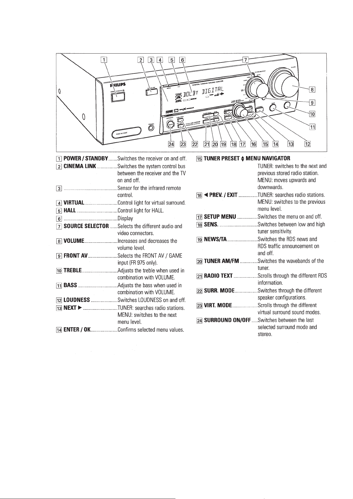
CONTROLS
PCS 105 701
INSTRUCTIONS FOR USE
07/08/2012
World of Free Manuals
2-2
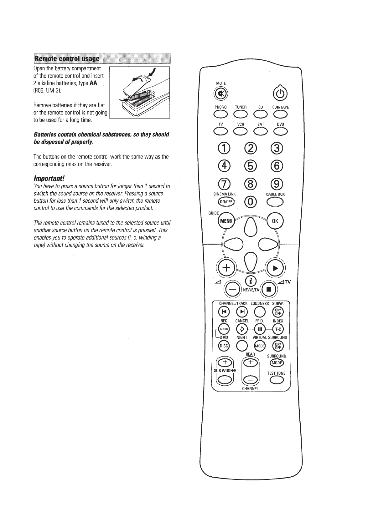
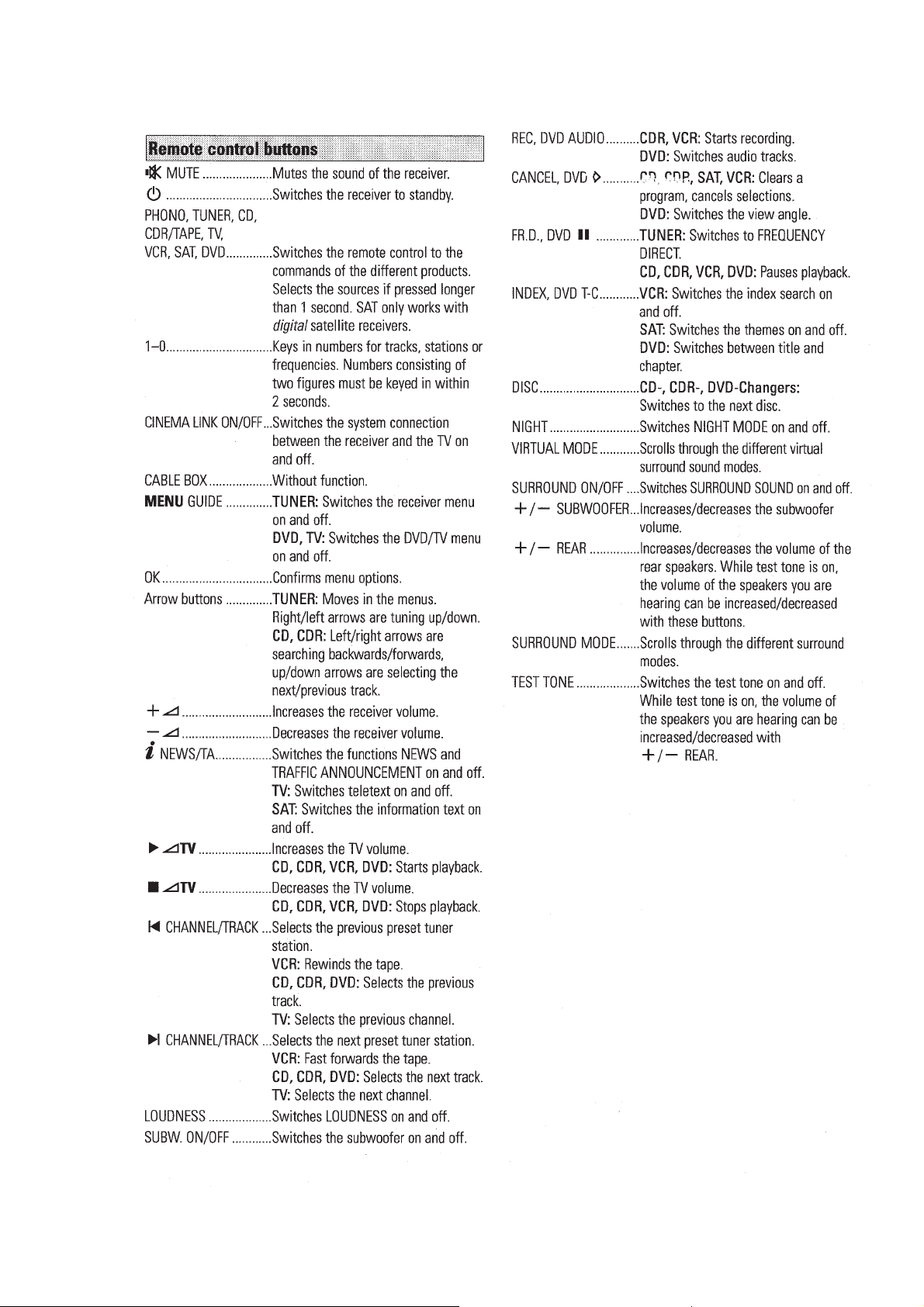
REMOTE CONTROL
PCS 105 702
INSTRUCTIONS FOR USE
07/08/2012
World of Free Manuals
2-3
REMOTE CONTROL
PCS 105 703
INSTRUCTIONS FOR USE
07/08/2012
World of Free Manuals
2-4
REMOTE CONTROL
PCS 105 704
INSTRUCTIONS FOR USE
07/08/2012
World of Free Manuals
2-5
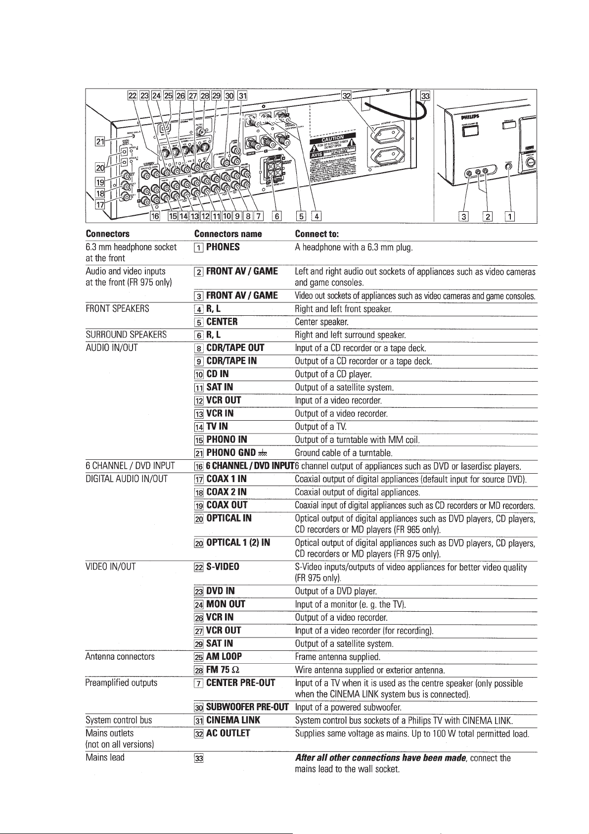
CONNECTORS
PCS 105 705
INSTRUCTIONS FOR USE
07/08/2012
World of Free Manuals
2-6
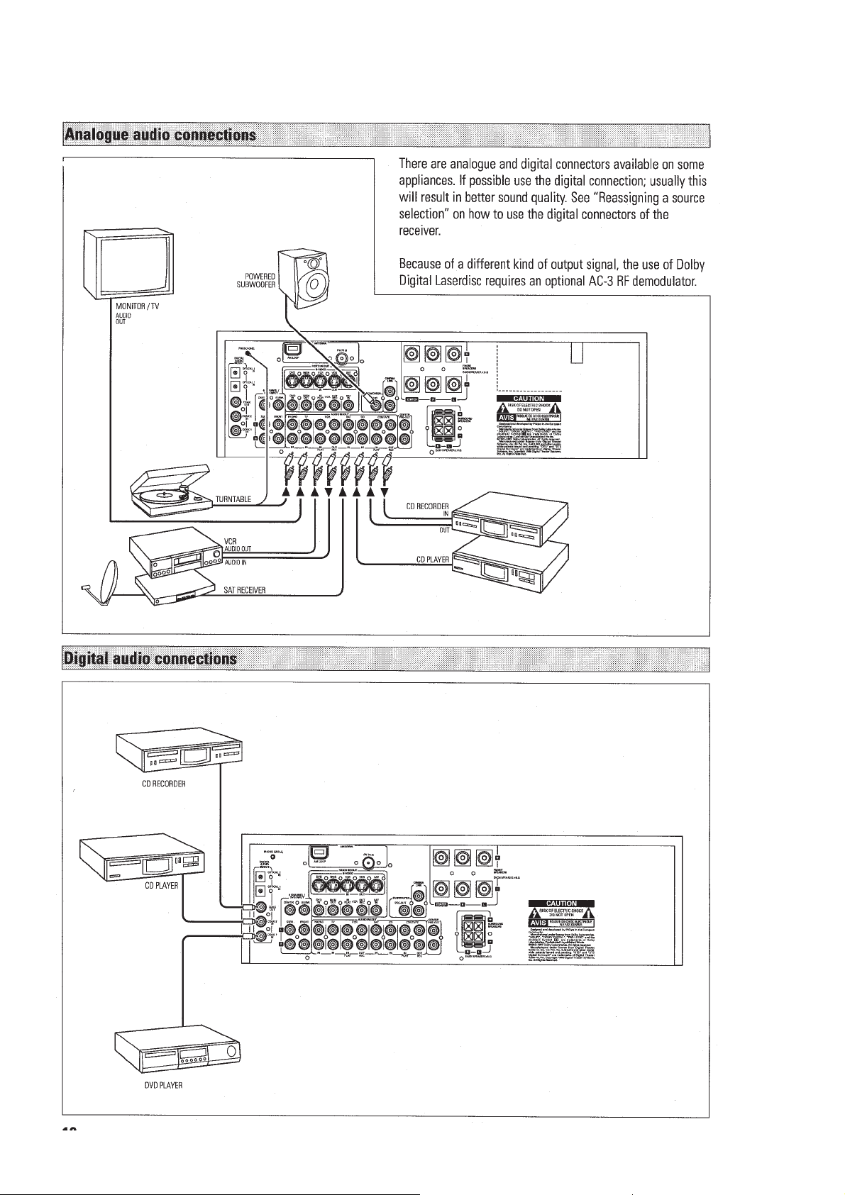
CONNECTIONS
PCS 105 706
7NSTRUCTIONS FOR USE
07/08/2012
World of Free Manuals
2-7
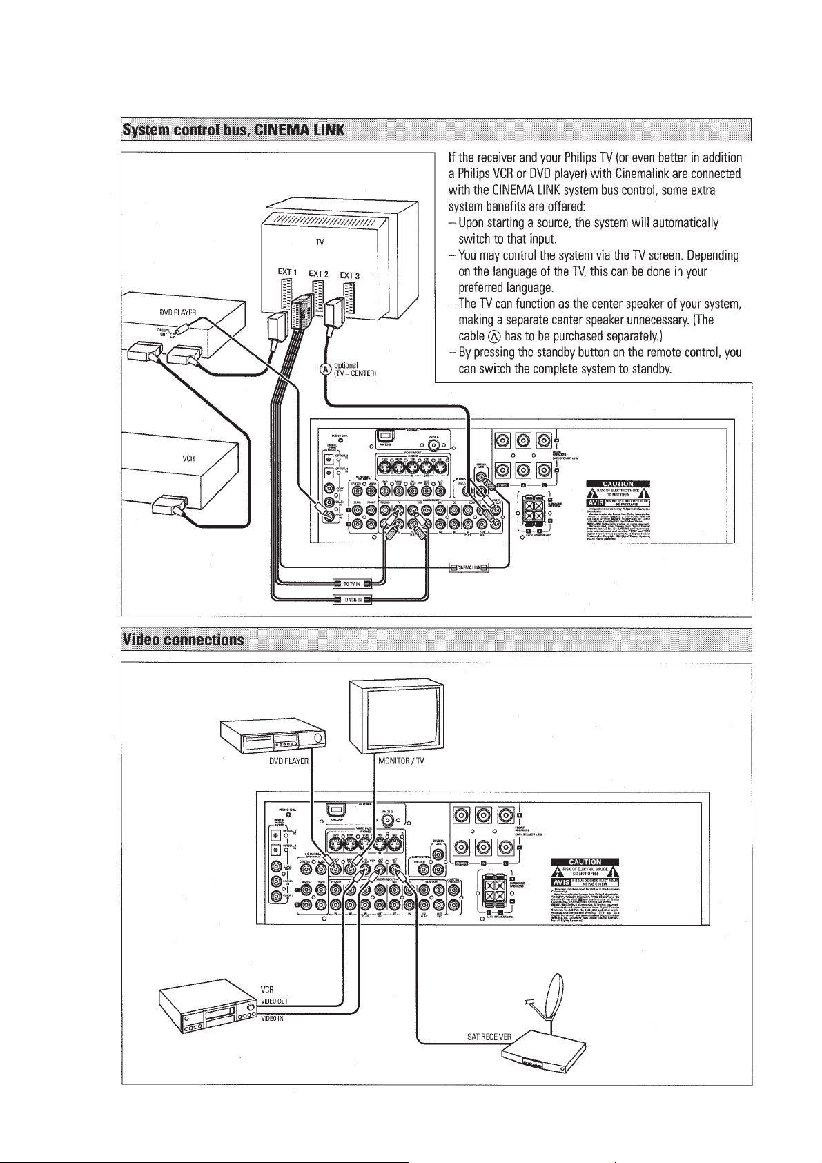
CONNECTIONS
PCS 105 707
INSTRUCTIONS FOR USE
07/08/2012
World of Free Manuals
2-8
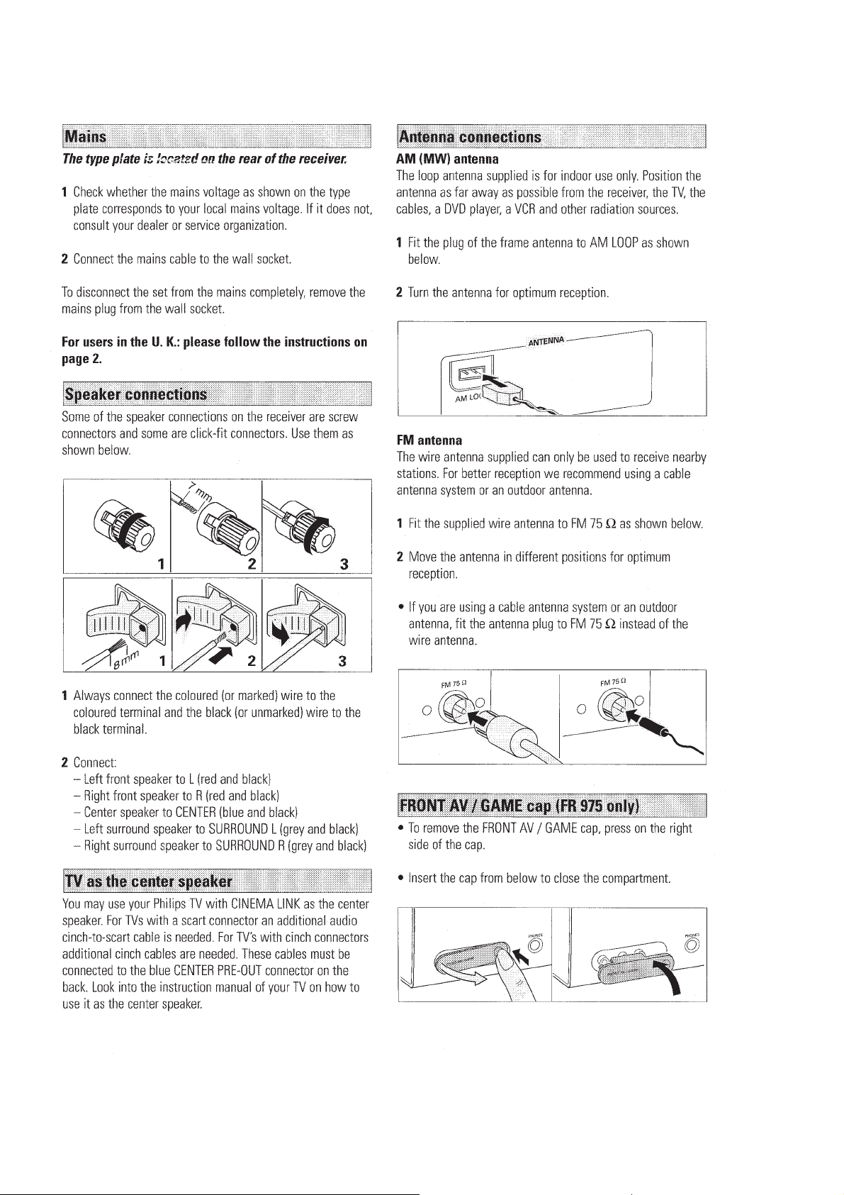
CONNECTIONS
PCS 105 708
INSTRUCTIONS FOR USE
07/08/2012
World of Free Manuals
2-9
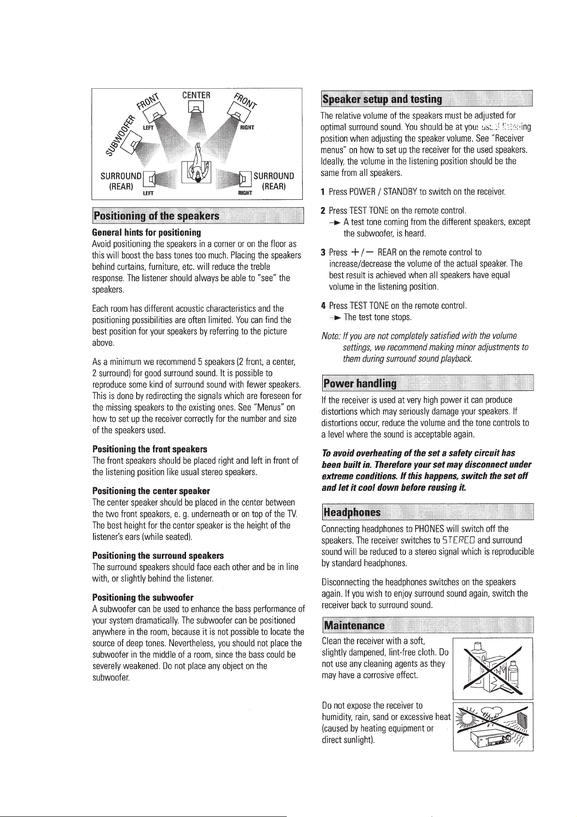
SYSTEM SETUP
PCS 105 709
INSTRUCTIONS FOR USE
07/08/2012
World of Free Manuals
2-10
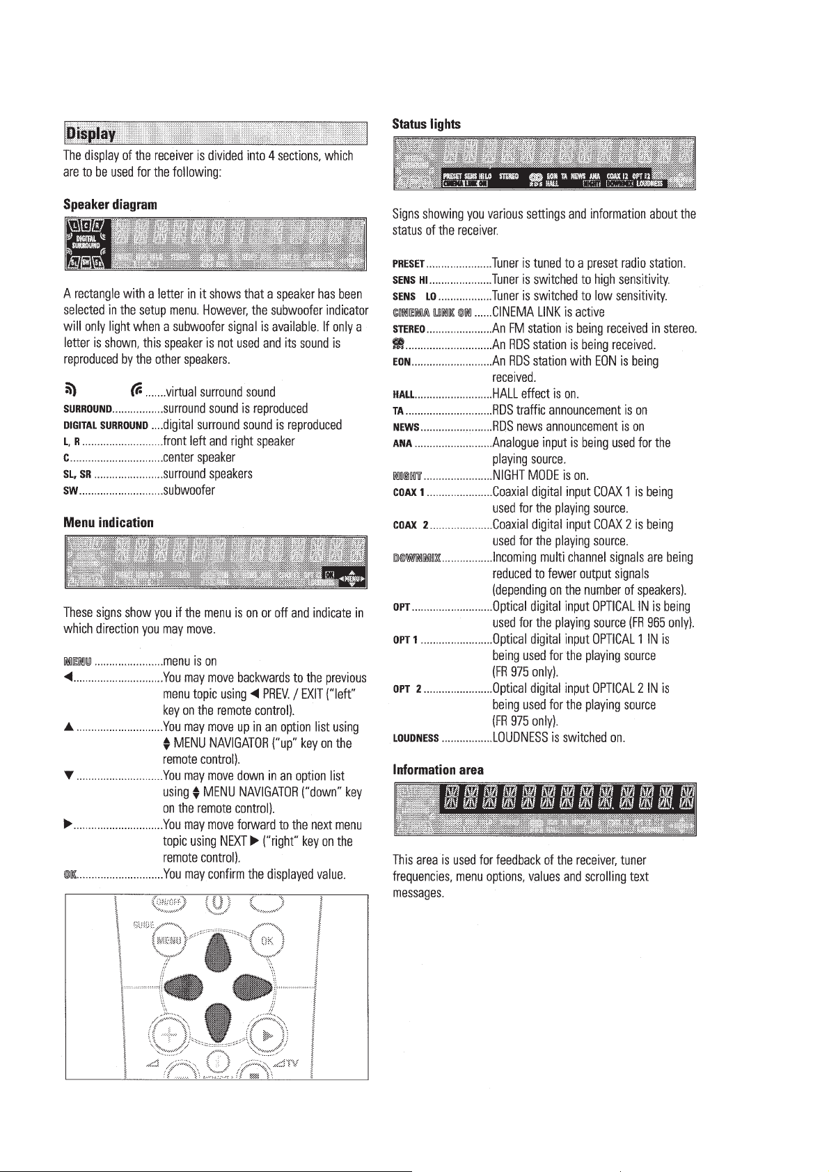
DISPLAY
PCS 105 710
INSTRUCTIONS FOR USE
07/08/2012
World of Free Manuals
2-11
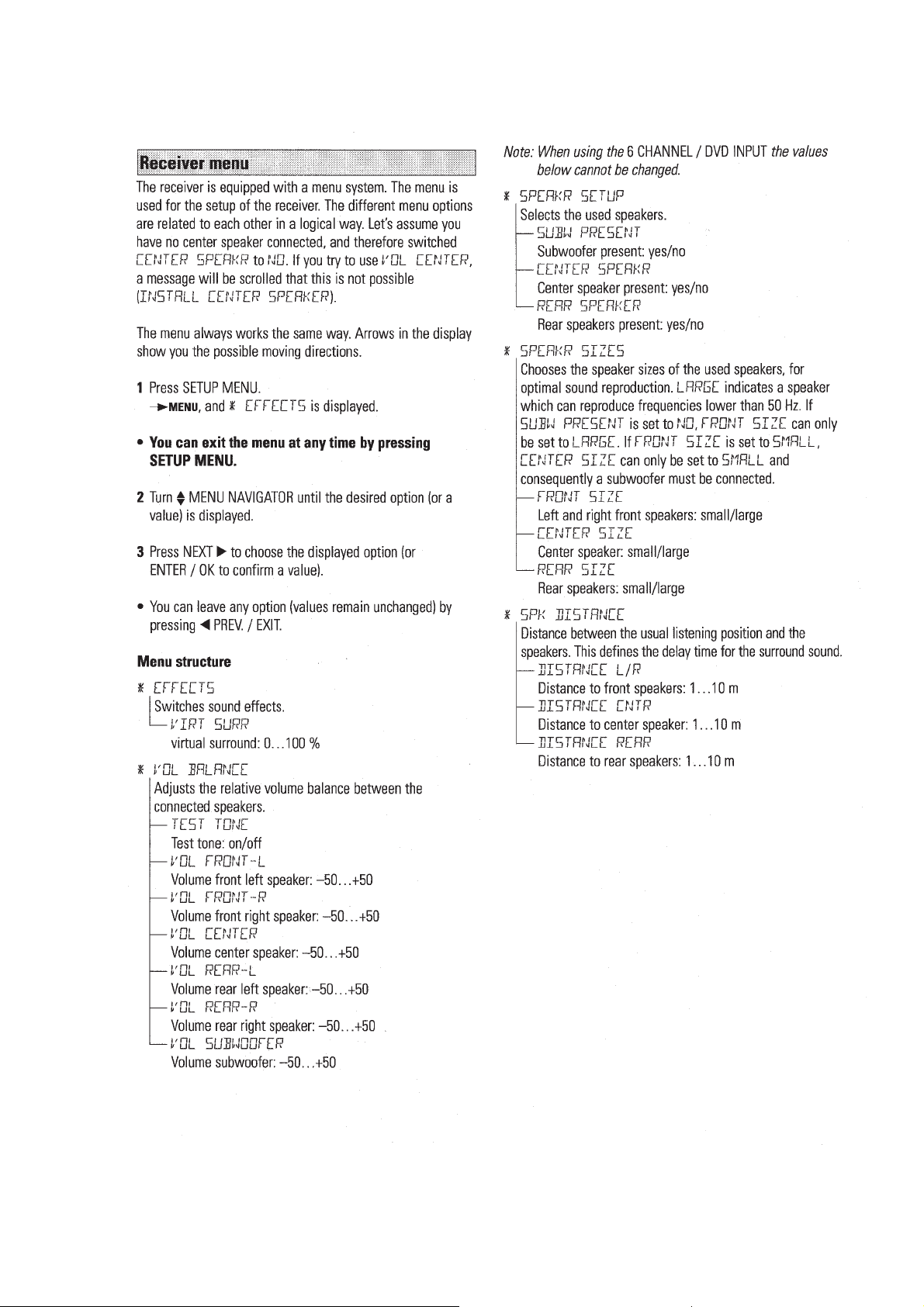
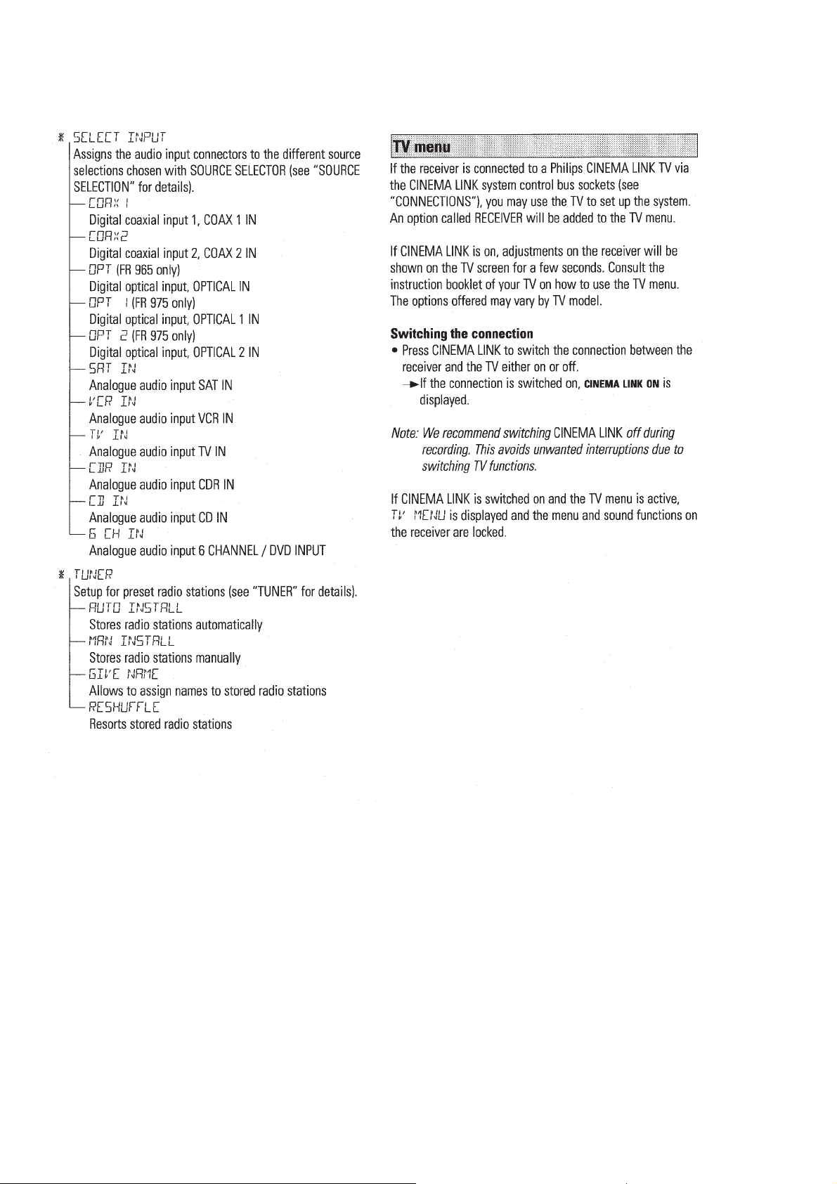
MENUS
PCS 105 711
INSTRUCTIONS FOR USE
07/08/2012
World of Free Manuals
2-12
MENUS
PCS 105 712
INSTRUCTIONS FOR USE
07/08/2012
World of Free Manuals
2-13
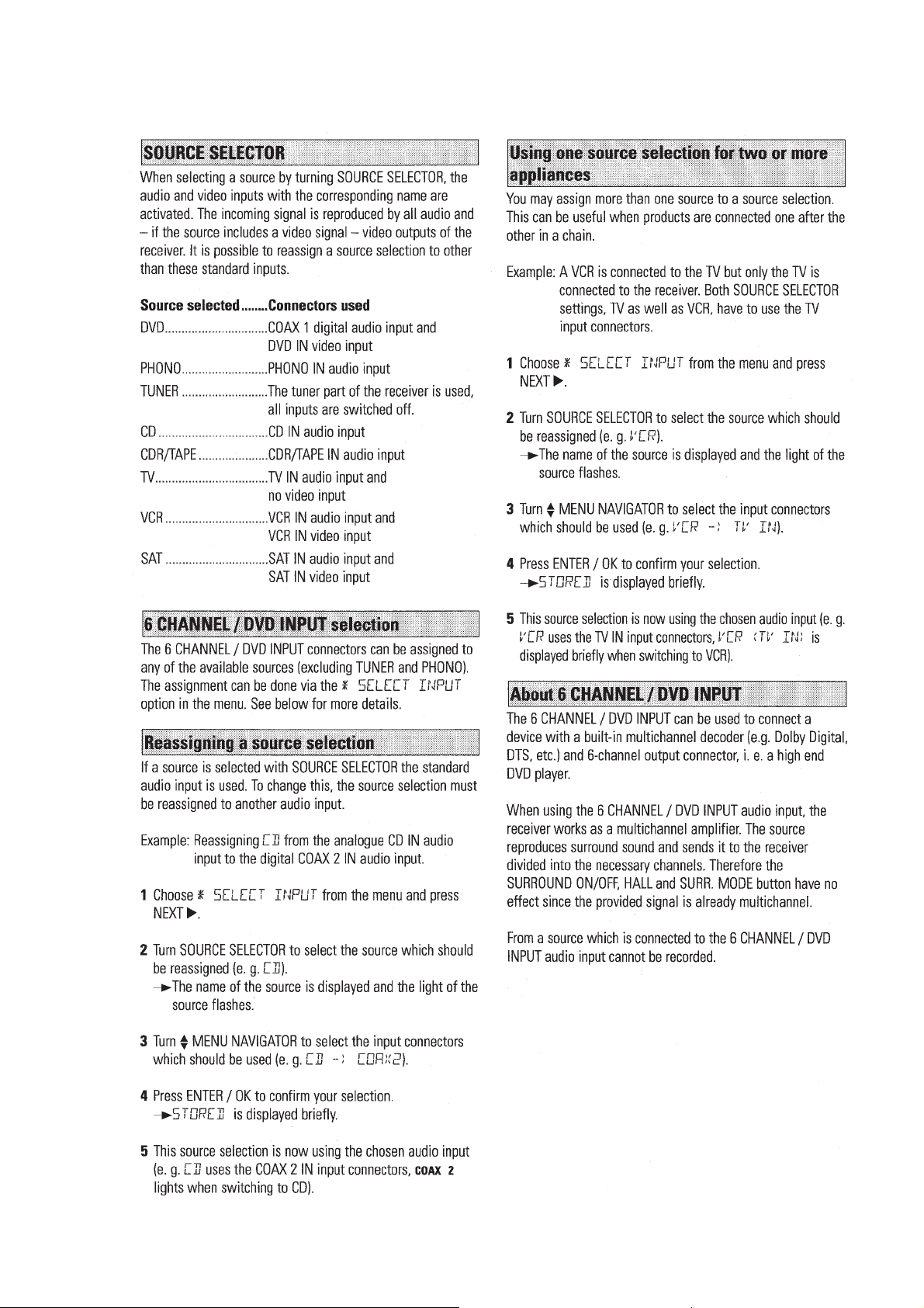
SOURCE SELECTION
PCS 105 713
INSTRUCTIONS FOR USE
07/08/2012
World of Free Manuals
2-14
PLAYBACK, RECORDING
PCS 105 714
INSTRUCTIONS FOR USE
07/08/2012
World of Free Manuals
2-15
SURROUND SOUND
PCS 105 715
INSTRUCTIONS FOR USE
07/08/2012
World of Free Manuals
2-16
SURROUND SOUND
PCS 105 716
INSTRUCTIONS FOR USE
07/08/2012
World of Free Manuals
2-17
TUNER
PCS 105 717
 Loading...