

Page 1

Forte Camera
Site Planning
Document
9347-0110 Rev B
Sec 1: Room Requirements........1-1
Sec 2: Room Layouts .................2-1
Sec 3: Anchor Details .................3-1
Sec 4: Gantry Cables..................4-1
Sec 5: Shipping Information........5-1
Sec 6: Floor Loading...................6-1
Philips Medical Systems
540 Alder Dr.
Milpitas, CA 95035
Page 2

Warranty Disclaimer
Philips provides this document without warranty of any kind, either implied or expressed,
including, but not limited to, the implied warranties of merchantability and fitness for a particular
purpose.
Limitation Of Liability
Philips has taken care to ensure the accuracy of this document. However, Philips assumes no
liability for errors or omissions and reserves the right to make changes without further notice to
any products herein to improve reliability, function, or design. Philips may make improvements
or changes in the product(s) or program(s) described in this document at any time.
About This Document
This document provides site planning information for customers planning to purchase a Forte
camera and their facility engineers, structural engineers, site planners and architects.
CAD Drawings
Drawings in a DWG format for the Forte system are downloadable from the following website
for architects planning room layouts:
http://apps1.medical.philips.com/documents
Copyright Notice
© May 1, 2003 Koninklijke Philips Electronics N.V. All rights reserved.
i
Page 3

Section 1
Room Requirements
General Information
Forte cameras consist of a Gantry, a Collimator Storage Unit (for holding up to four
pairs of heavy collimators), a Patient Table, an Acquisition Terminal and a
Processing Workstation (also called a PegBlade).
The Gantry is a stationary “ring-shaped” device which Philips anchors to the floor.
The Gantry supports two Detectors from which the system collects images of the
patient. See illustration on page 1-3.
The Patient Table is on wheels, but, unless moved out of the way to accommodate
gurney-bound patients, remains in the same location. As shown on page 1-3, the
Patient Table includes a moveable Pallet which translates the patient in and out of
the Gantry Ring.
For Emission Computed Tomography (ECT) studies, the two Detectors rotate
around a patient lying on the Patient Table in the center of the Gantry Ring.
For Total Body Studies, the two detectors remain above and below the patient. The
Patient Table moves the Pallet (and patient) in and out of the Gantry Ring.
To image patients on gurneys, operators move the Patient Table out of the way and
place the gurney under the camera but perpendicular to the normal table position.
Forte Models
There are two models of Forte Cameras:
• Forte with Atlas Electronics Rack (Forte Atlas) - manufactured before
November 2000 which requires an additional electronic rack in the room.
• Forte with Power Pack (Forte Power Pack) - manufactured after December
2000 which have a slightly larger compartment behind the Gantry. That
compartment contains the electronic components formerly contained in the
separate Atlas Electronics Rack.
Collimator Storage Unit
The Collimator Storage Unit may contain up to eight collimators (four pairs).
Collimators are 21" x 26" (53cm x 66cm) sheets of lead of various thicknesses.
Collimators weigh between 110 and 235 lbs (50 and 107 kg).
Prior to performing clinical studies, the operator must transfer a pair of collimators
from the Collimator Storage Unit to the pair of Detectors on the Gantry. To do
1-1
Page 4

Section 1: Room Requirements
collimator transfers, the Collimator Storage Unit is on wheels. It moves between
“park” and “exchange” positions along an arc around the corner of the Gantry.
Left and Right Configurations
Philips can install the Collimator Storage Unit on either the left or right side of the
Gantry.
Philips recommends installing the Collimator Storage Unit on the side of the Gantry
where the patient enters the room. This allows operators to assist the patient getting
on or off the table and also reach controls on the Display Panel on top of the
Collimator Storage Unit.
The operator will also want the Acquisition Terminal on the same side of the Patient
Table as the Collimator Storage Unit. Other configurations will require the operator
to frequently walk around the Patient Table.
Section 2 contains illustrations of rooms with left and right Collimator Storage
Units. Those illustrations show recommended directions of patient access and
locations of the Acquisition Terminal.
Air Conditioning Requirements
The Forte camera has the following heat loads:
Forte System PegBlade PegBlade Monitor 6.0 KVA UPS
(optional)
5,542 BTU/hr 854 BTU/hr 544 BTU/hr 1,771 BTU/hr
388 Cal/sec 60 Cal/sec 38 Cal/sec 124 Cal/sec
1,623 watts 250 watts 159 watts 519 watts
The camera room HVAC system must maintain the temperature between 60°- 75° F
(16° - 24° C) with less than 10° F (5° C) variation per hour. Humidity must be
between 20% - 75%. These requirements are 24 hours per day, 7 days per week.
Floor Levelness Requirements
The floor under the four Patient Table wheels must be at the same level (±0.25" or 6
mm) as the floor under the Gantry .
The floor under the Collimator Storage Unit rails must be at the same level (±0.125"
or 3 mm) as the floor under the Gantry.
If floors do not meet these requirements, the customer will need to correct the floor
levelness problem before Philips can begin an installation. To avoid trip hazards near
the Gantry, Collimator Storage Unit and Patient Table, any floor correction measures
(such as grout) must taper down to the existing floor away from the Gantry,
Collimator Storage Unit and Patient Table. See illustration on page 6-8.
1-2
Page 5

Section 1: Room Requirements
Detector #1
Gantry
Tower
(moves with Pallet)
Pallet
Detector #2
Collimator Storage Unit
(rails on floor not shown)
Base
(doesn't move during studies)
Patient Table
Forte Gantry, Collimator Storage Unit and Patient Table.
1-3
Page 6
Section 1: Room Requirements
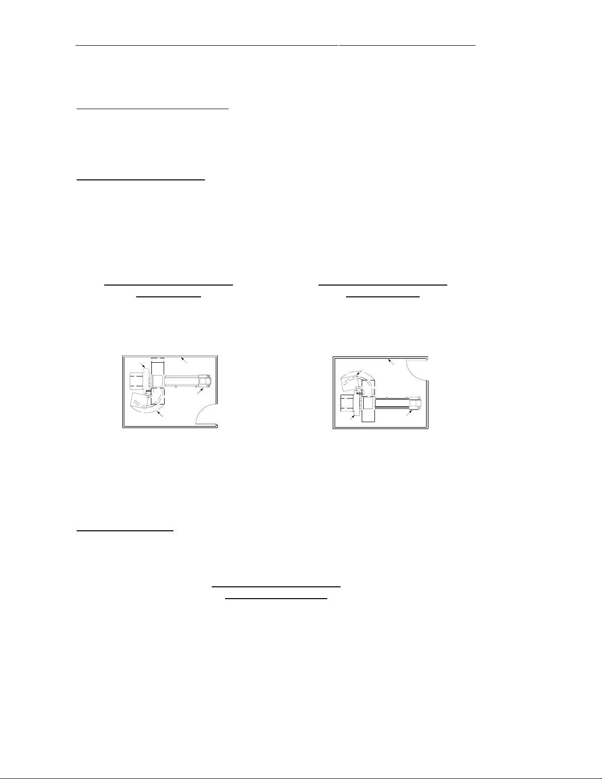
Room Size Requirements
Room size requirements are slightly different for Forte Power Pack and Forte Atlas
cameras. Room layout drawings appear in Section 2.
Forte Power Pack Cameras
For Forte Power Pack Cameras, the room sizes requirements differ slightly
depending on whether the Collimator Storage Unit is on the left or right side of the
Gantry.
Although larger rooms are preferable, acceptably small rooms for Forte Power Pack
cameras may have these dimensions:
Collimator Storage Unit on
left of Gantry
Collimator Storage Unit on
right of Gantry
Width: 13' - 6" (411 cm)
Length: 18' (549 cm)
Height: 7' - 7" (231 cm)
Gantry
Patient Table
Collimator
Storage Unit
Room
Width: 12' - 10" (391 cm)
Length: 18' (549 cm)
Height: 7' - 7" (231 cm)
Gantry
Collimator
Storage Unit
Room
Patient Table
Forte Power Pack room sizes smaller than 12' - 10" x 18' require approval by
Philips Milpitas Site Planning Department.
For new construction, architects should consider increasing the room length to 20'.
Forte Atlas Cameras
For Forte Atlas Cameras, room size requirements are the same for left and right
Collimator Storage Units. An acceptably small room may have these dimensions:
Collimator Storage Unit on
left or right of Gantry
Width: 13' - 6" (411 cm)
Length: 18' (549 cm)
Height: 7' - 7" (231 cm)
Forte Atlas Cameras with room sizes smaller than 13' - 6" x 18' require approval by
Philips Milpitas Site Planning Department.
For new construction, architects should consider increasing the room length to 20'.
1-4
Page 7
Section 1: Room Requirements
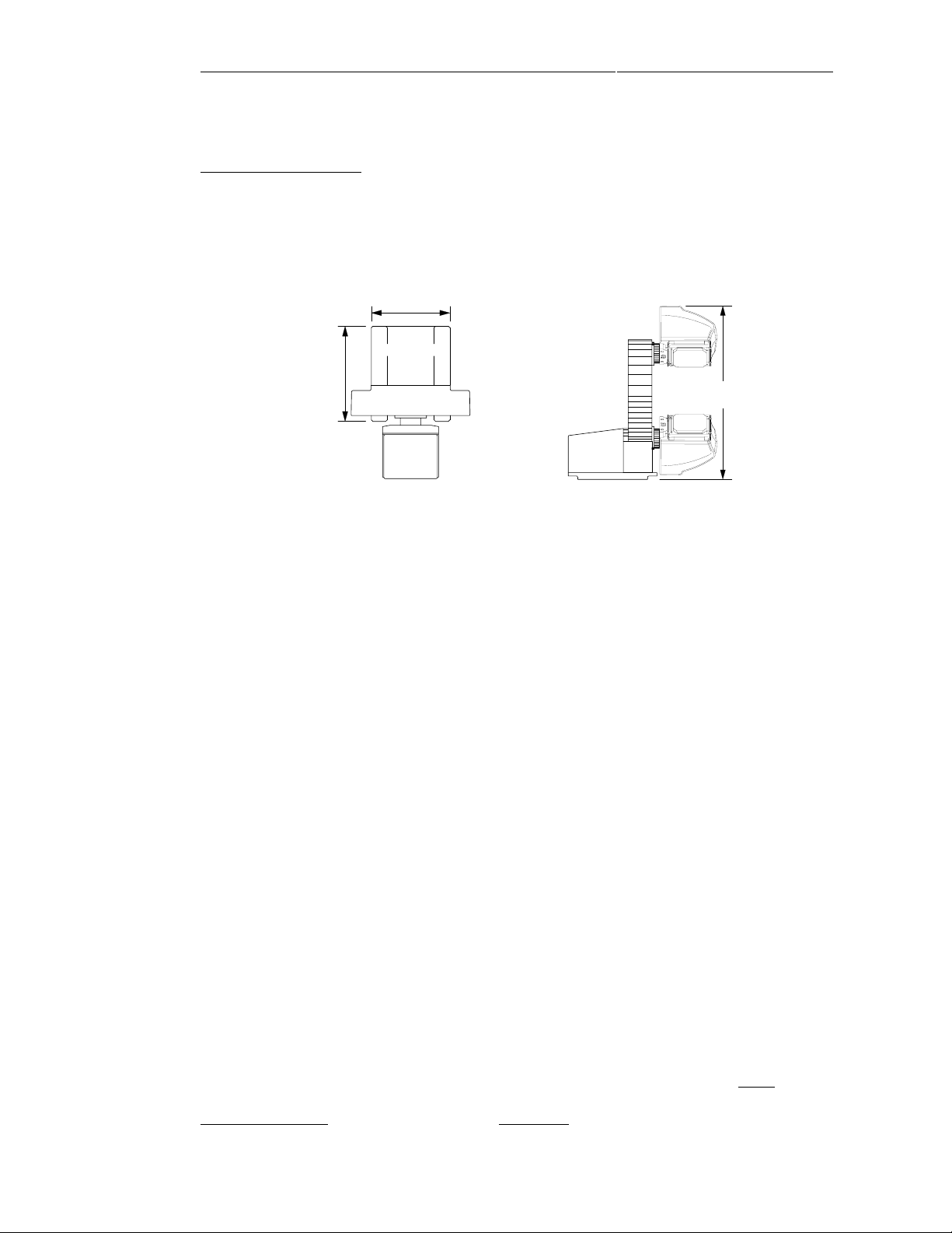
Equipment Sizes
Forte Power Pack Gantry base W: 39", D: 47", H: 88" 4,512 lbs
(weight is without Collimators) (99 x 119 x 224cm) (2,047 kg)
Forte Atlas Gantry base W: 39", D: 47", H: 88" 4,348 lbs
(weight is without Collimators) (99 x 119 x 224cm) (1,972 kg)
39"
Gantry
47"
Base
Gantry Ring
Detectors
88"
[224cm]
Top View of Gantry
Side View
Collimator Storage Unit W: 31", D: 38", H: 61" 1,068 lbs
(weight is without Collimators) (79 x 97 x 155cm) (484 kg)
Patient Table W: 27", D: 110", H: 37" 850 lbs
(69 x 279 x 94cm) (386 kg)
Processing Workstation (PegBlade) W: 18", D: 18", H: 5" 27 lbs
(placed on customer’s desktop) (46 x 46 x 12cm) (12 kg)
Pegasys monitor W: 20", D: 20", H: 20" 69 lbs
(placed on customer’s desktop) (50 x 50 x 50 cm) (32 kg)
Acquisition Terminal W: 33", D: 30", H: 55" 185 lbs
(84 x 76 x 140cm) (84 kg)
6.0 KVA UPS (optional) W: 19", D: 29", H: 14" 294 lbs
(48 x 73 x 36cm) (133 kg)
Codonics Printer (optional) W: 17", D: 21", H: 12" 55 lbs
(placed on customer’s desktop) (43 x 53 x 30cm) (25 kg)
Atlas Electronics Rack W: 34", D: 22", H: 34" 211 lbs
(not part of Forte Power Pack) (86 x 56 x 86cm) (96 kg)
Important: Unless the floor is a ground-level, reinforced 3,000 psi (211 kg/cm2),
4.5" thick, poured on grade concrete slab, a licensed structural engineer must evaluate
floor loading. To evaluate floor loading, a structural engineer will need the data in
Sections 3 and 6 of this document. See Section 5 for shipping sizes or weights.
1-5
Page 8

Power Requirements
Section 1: Room Requirements
Camera
. Power requirments for the Forte Camera1 are as follows:
UPS (optional) 6.0 KVA
(manufactured by APC)
Voltage/Current Requirement (with or without UPS): 208 - 240 VAC, 30 amp
Peak current: 15.3 amp at 208 VAC
Steady state current: 4.2 amp at 208 VAC
Phase: Single Phase
Receptacle (with or without UPS): L6-30R
(dedicated line)
Processing Workstation. Power requirements for Processing Station (PegBlade) are:
Voltage: 115 VAC (U.S.)
220 VAC (International)
Current: 5 amp @115 VAC (U.S.)
2.5 amp @ 220 VAC
(International)
Receptacle: Nema 5-20 (dedicated line
not required)
Vibration Specifications
Nuclear medicine cameras do not have floor vibration specifications. This is because
(1) image collection durations are long (10 - 300 seconds, or more) and floor
vibration durations are much smaller, (2) vibrations are typically sinusoidal and,
therefore, tend to cancel out, and (3) the patient table and detector/gantry assemblies
are both floor mounted and, therefore, vibrate together.
________
1
In Forte Atlas cameras, the Atlas Electronics Rack provides power to the Gantry, Collimator
Storage Unit, Patient Table and Acquisition Terminal.
In Forte Power Pack cameras, the Gantry provides power to the Collimator Storage Unit, Patient
Table and Acquisition Terminal.
Forte Atlas and Forte Power Pack cameras have the same power requirements.
1-6
Page 9
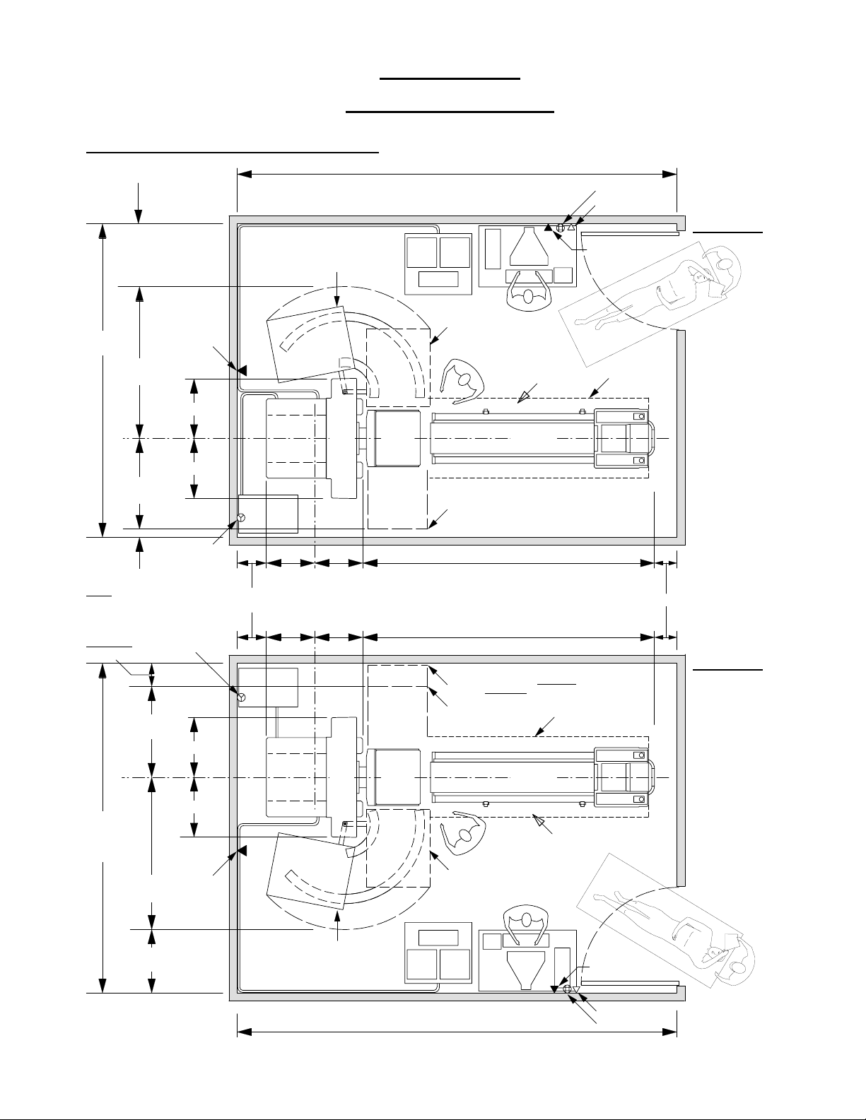
Room Layouts
Forte Power Pack with UPS Power
31" (79cm) shown;
4" (10cm) min
12'-10"
(391cm)
74.5"
(189cm)
C
L
(Gantry)
44.5"
(113 cm)
Twin RJ45
29.5" (75 cm)
29.5" (75 cm)
UPS
Collimator Storage Unit
(park position)
Gantry
Section 2:
(20' recommended for new construction)
1" cable
18'-0" (549cm)
Acquisition
Terminal (mobile)
Collimator
Storage Unit
(exchange
position)
Detectors
Worst case for detector cover
Processing Station
(desk top)
Operator
Position
Patient Table
Patient
Access
115 VAC 15 A
Phone line
Twin RJ45
Lateral table
motion limit
Option 1
Note:
Options 1 and 2
illustrate acceptably
small rooms.
Larger rooms are
preferable.
Rooms smaller
than 12'-10" x 18'
require approval
by Philips Milpitas
Site Planning Dept.
4" (10cm) minimum
Note:
12" shown,
4" minimum,
42" required
for stretcher
head-to-toe
imaging
(113 cm)
C
L
(Gantry)
13'-6" (411cm)
(for head-to-toe
imaging, 17'
recommended)
(189cm)
208-240VAC
Single Phase
30 Amp, L6-30R
208-240VAC
Single Phase
30 Amp, L6-30R
44.5"
29.5" (75 cm)
29.5" (75 cm)
Twin RJ45
74.5"
31" (79cm) shown;
4" (10cm) min
14" shown;
8" min
UPS
24"
24"
C
L
(Gantry)
C
L
24"24"
Gantry
Collimator Storage Unit
(park position)
1" cable
Detectors
143" (363cm)
11" shown; 4" min
143" (363cm)
Worst case for stretcher abdominal imaging
(stretcher head-to-toe imaging requires 30" larger room)
Worst case for detector cover
Patient Table
Operator
Position
Collimator
Storage Unit
(exchange
position)
Lateral table motion limit
Patient
Access
Twin RJ45
Option 2
5/1/03
Acquisition
Terminal (mobile)
18'-0" (549cm)
2-1
Processing Station
(desk top)
Phone line
115 VAC 15 A
Page 10

Forte Atlas with UPS Power
31" (79cm) shown;
4" (10cm) min
13'-6"
(411cm)
74.5"
(189cm)
C
C
L
L
(Gantry)
44.5"
(113cm)
29.5", (75cm)
29.5", (75cm)
Twin RJ45
2" cable
Collimator Storage Unit
UPS
(park position)
Gantry
Atlas
Electronics
Rack
34" x 22"
18'-0" (549cm)
(20' recommended for new construction)
Acquisition
Terminal (mobile)
1" cable
Collimator
Storage Unit
(exchange
position)
Detectors
Worst case
detector cover
Processing Station
(desk top)
Operator
Position
Patient
Access
Patient Table
115 VAC 15 A
Phone line
Twin RJ45
Lateral table
motion limit
Option 1
Note:
Options 1 and 2
illustrate acceptably
small rooms.
Larger rooms are
preferable.
Rooms smaller
than 13'-6" x 18'
require approval
by Philips Milpitas
Site Planning Dept.
12" (30cm) shown
4" (10cm) minimum
Note:
12" shown,
4" minimum,
42" required
for stretcher
head-to-toe
imaging
44.5"
(113 cm)
C
L
(Gantry)
74.5"
(189cm)
13'-6" (411cm)
(for head-to-toe
imaging, 17'
recommended)
31" (79cm) shown;
4" (10cm) min
208-240VAC
Single Phase
30 Amp, L6-30R
208-240VAC
Single Phase
30 Amp, L6-30R
Twin RJ45
29.5" (75 cm)
29.5" (75 cm)
14" shown;
8" min
(Gantry)
UPS
2" cable
Collimator Storage Unit
C
24"24"
L
C
L
24"24"
34" x 22"
Atlas
Electronics
Rack
Gantry
(park position)
1" cable
Detectors
143" (363cm)
143" (363cm)
Worst case for stretcher abdominal imaging
head-to-toe imaging requires 30" larger room)
(stretcher
Worst case for detector cover
Patient Table
Operator
Position
Collimator
Storage Unit
(exchange
position)
Lateral table motion limit
Patient
Access
Twin RJ45
11" shown; 4" min
Option 2
1/28/03
Acquisition
Terminal (mobile)
18'-0" (549cm)
2-2
Processing Station
(desk top)
Phone line
115 VAC 15 A
Page 11

Section 3
Anchor Details
Anchor Hole Pattern
Philips installers (not customer contractors) will anchor the Forte Gantry to the floor
during the installation. This diagram shows the location of the anchors.
Option 1
18.4", 46.7cm
12.7", 32.3cm
12.7", 32.3cm
18.4", 46.7cm
48.5", 123cm
56.0", 142cm
18.4", 46.7cm
12.7", 32.3cm
12.7", 32.3cm
18.4", 46.7cm
0
0
C
(Gantry)
19.1", 48.5cm
38.0", 96.5cm
22.8", 57.9cm
C
(Gantry)
L
0
L
Holes for Gantry anchors
1/2" dia. (qty = 16)
C
(Gantry)
L
Note: Hole locations are only approximate.
Philips installers will determine exact locations
during installation.
19.1", 48.5cm
22.8", 57.9cm
C
(Gantry)
L
Holes for Gantry anchors
1/2" dia. (qty = 16)
Option 2
3-1
Page 12

Section 3: Anchor Details
California OSHPD Information
In September 2002, Philips applied for California “Pre-approval of Anchorage for
Fixed Hospital Equipment” for the Forte Power Pack. We based the application on
the new 2001 California Building Code (CBC).
That application, and an older 1998 CBC Pre-approval, are on this website:
http://apps1.medical.philips.com/documents
Anchor Specifications
Philips installers use the following expansion anchors for the Forte Gantry.
Non-Seismic (non-California) Sites
Min. Slab Camera
Manufacturer Model Diameter ICBO # Embed Thickness Elevation
Hilti Kwik-Bolt II 1/2" 4627 3.5" 4.5" No restrictions
Seismic (California) Sites
Min. Slab Camera
Manufacturer Model Diameter ICBO # Embed Thickness Elevation
Hilti Kwik-Bolt II 1/2" 4627 3.5" 4.5" Ground only
Hilti Kwik-Bolt II 1/2" 4627 4" 5.25" less than 1/3
building height
Camera Elevation is the ratio of the camera room floor height and the building roof
height (both with respect to ground level).
Note: Sites that cannot use anchors (because of slab thickness or camera elevation
problems) may be through bolted. To do so, a customer must retain a licensed
structural engineer to specify the grade of steel for the bolts and the size of
under-the-floor plates or washers. The customer must provide the bolts and
under-the-floor plates or washers.
For structural engineers specifying a steel plate on top of the floor, the last page in
Section 6 describes our requirements.
3-2
Page 13

Section 4
Gantry Cables
Gantry Cable Lengths
Forte Power Pack Cameras have the cable lengths shown below.
NEMA L6-30 Receptacle (hospital provided)
NEMA L6-30 Plug
Table
Cable between Table
and Gantry is 14' (4m)
Note:
1. The power cord always
comes from the right rear
corner of the Gantry.
2. If the Exchanger is on the
right side of the Gantry
(as shown), cables to
the Acquisition Terminal,
Processing Workstation and
Table always come from
right side of the Gantry.
If the Exchanger is on the
left, the same cables come
from the left side of the Gantry.
NEMA
5-20 Receptacle
(hospital provided)
NEMA
5-20 Plug
9.5' (2.9m)
5/16" (8mm) dia
Power Cord
Power Cord
Ethernet
Category 5
Twisted-Pair 10baseT
(various lengths)
Processing
Workstation
(desk top)
14' (4.3m)
Gantry with Power Pack
25', 50', 75' or 100'
(7.6m, 15m, 23m, 30m) long
1" (2.5cm) dia with 3" (7.6cm)
non-removable plugs on each end.
Typically placed on floor,
but may be pushed
through 2" (5cm) round
conduit by removing
plug housing. Bending
radius = 3.5".
Acquisition
Terminal
(mobile)
Note:
Philips installers will perform all
cable connections. If a hospital
insists that cables be run through
walls, ceilings or conduits,
hospital personnel must run those
cables through those structures.
4-1
Page 14

Section 4: Gantry Cables
Gantry Cable Lengths (continued)
Forte Atlas Cameras have the cable lengths shown below.
NEMA L6-30 Receptacle (hospital provided)
NEMA L6-30 Plug
Power Cord
14' (4.3m)
Gantry
14' (4m)
Table
(typically placed on floor)
NEMA
5-20 Receptacle
(hospital provided)
NEMA
5-20 Plug
16' (5m)
2" (5 cm) diameter
9.5' (2.9m)
5/16" (8mm) dia
Power Cord
Ethernet
Category 5
Twisted-Pair 10baseT
(various lengths)
Processing
Workstation
(desk top)
Atlas
Electronics
Rack
25', 50', 75' or 100'
(7.6m, 15m, 23m, 30m) long
1" (2.5cm) dia with 3" (7.6cm)
non-removable plugs on each end.
Typically placed on floor,
but may be pushed
through 2" (5cm) round
conduit by removing
plug housing. Bending
radius = 3.5".
Acquisition
Terminal
(mobile)
Note:
Philips installers will perform all
cable connections. If a hospital
insists that cables be run through
walls, ceilings or conduits,
hospital personnel must run those
cables through those structures.
4-2
Page 15

Section 5
Shipping Information
Gantry (Shipping Size and Weight)
The weight of the Gantry (which Philips ships without Detectors or Power Pack) is:
Gantry: 2,156 lbs (978 Kg)
Crate: 350 lbs (159 Kg)
Total: 2,506 lbs (1,137 Kg)
The crated size of the Gantry
is shown on the right.
Document 9346-0052 contains
rigger information and is
69.5"
[176.5cm]
[120.7cm]
available on this website:
http://apps1.medical.philips.com/documents
Top View Side View
The weight of the Gantry on the dolly Philips uses
to transport the Gantry within a hospital is:
Gantry: 2,156 lbs (978 Kg)
Dolly: 600 lbs (272 Kg) (est)
Total: 2,756 lbs (1,250 Kg) (est)
The size of the Gantry on dolly is:
91"
[232cm]
The 91" (232cm) length may be reduced
to 73" (185cm) by use of shorter dolly plates
(which come with dolly).
47.5"
47.5"
[120.7cm]
80.0"
[203.2cm]
70"
[178cm]
Top View
40"
[101cm]
5-1
To turn a Forte and dolly requires:
• 61" with 91" dolly plates, and
• 54" with 73" dolly plates.
Page 16

Section 5: Shipping Information
Collimator Storage Unit (Shipping Size and Weight)
The shippping weight of the Collimator Storage Unit (which Philips ships without
collimators) is:
Collimator Storage Unit: 1,068 lbs (484 Kg)
Crate: 150 lbs (68 Kg) (est)
Total: 1,218 lbs (552 Kg) (est)
The uncrated size of Collimator Storage
Unit is shown on the right.
61"
[155cm]
33.5"
[85cm]
Patient Table (Shipping Size and Weight)
The shippping weight of the Patient Table is:
Patient Table: 850 lbs (386 Kg) (est)
Crate: 150 lbs (68 Kg) (est)
Total: 1,000 lbs (454 Kg)
The uncrated size of Patient Table
is shown on the right.
40"
[102cm]
If corners or elevators are too small
to accomodate a 110" long table, the
site must hire a rigger to get the table
into the room.
Rigger information (document 9346-0052)
is available on this website:
http://apps1.medical.philips.com/documents
37"
[194cm]
(minimum)
110"
[280cm]
27"
[69cm]
Philips Engineers may obtain 9346-0052 rigger document from the “NM FS &
Customer Support” hotlink on the Philips Milpitas internal website.
5-2
Page 17

Section 6
Floor Loading
General Floor Loading Information
Unless the floor is a reinforced 3,000 psi (211 kg/cm2), 4.5" thick, concrete slab
poured on grade, a licensed structural engineer must evaluate floor loading capacity
using the data in this section.
Refer to Section 1 of this document for explanations of the Forte Gantry, Collimator
Storage Unit and Patient Table functions.
Section 3 describes anchor details.
This section presents floor loading requirements starting with the entire area of a
typically sized room. This section also defines the loads under specific parts of the
Forte Camera system (Gantry, Collimator Storage Unit and Table).
Floor loads depend on which collimators a customer purchases. This section contains
calculations for a probable worst case set of collimators (pairs of LEGP, VXGP,
MEGP and HEGP collimators).
Below is a list of all possible collimator types and weights so structural engineers can
perform site-specific floor load calculations:
LEGP = 110 lbs MEGP = 218 lbs
LEHR = 114 lbs HEGP = 235 lbs
VXGP = 110 lbs HEHR = 240 lbs (estimate)
VXHR = 119 lbs MCD shields = 253 lbs (estimate)
VXUR = 126 lbs Pinhole = 260 lbs
Collimators come in pairs except the Pinhole which comes as a single collimator.
The calculations in this section pertain to Forte Power Pack cameras. Forte Atlas
cameras (which are older) have a smaller compartment behind the Gantry and are 164
lbs lighter. However, Forte Atlas camera installations include an extra piece of
equipment. The extra equipment, an Atlas Electonics Rack, weighs 211 lbs.
Seismic
The calculations in this section do not include seismic loads. Sites that must meet
seismic requirements should obtain a copy of Philip’s California Forte OSHPD
Pre-Approval Package from this website:
http://apps1.medical.philips.com/documents
Note: The OSHPD package assumes a camera weight that includes two 295 lb UHGP
collimators (which Philips no longer sells). The following calculations treat camera
and collimator weights separately.
6-1
Page 18

Section 6: Floor Loading
“Room” Floor Loading
Without Collimators
Components Weight
PegBlade & Monitor 96
Acquisition Terminal 185
Gantry (w/o collimators) 4,512
empty Collimator Storage 1,068
Patient Table 850
Patient 400
Technologists 400 (200+200)
UPS (optional) 294
Total 7,805 lbs
Room= 13.5 x 18 = 243 sq ft
Collimator Storage Unit
(storage position)
13'-6"
Area
Terminal (mobile)
1" cable
18'
Acquisition
Storage Unit
Collimator
(exchange
position)
Pegasys Ultra 60
(desk top)
Room Floor Loading (w/o collimators)
With Collimators
Components Weight
PegUltra & Monitor 96
Acquisition Terminal 185
Gantry (w/o collimators) 4,512
empty Collimator Storage 1,068
Patient Table 850
Patient 400
Technologists 400 (200+200)
UPS (optional) 294
Collimators in Storage Unit:
LEGP 220 (2 x 110)
VXGP 220 (2 x 110)
MEGP 436 (2 x 218)
Collimators on Detectors:
HEGP 470 (2 x 235)
Gantry
UPS
= 7,805 ÷ 243 = 32 lbs/ft
Detectors
2
Worst case
detector cover
Patient Table
Total 9,151 lbs
Room Floor Loading (w/ collimators) = 9,127 ÷ 243 = 38 lbs/ft
2
Note: If a structural engineer does not know which collimators a customer will
purchase or if a customer will likely add other collimators in the future,
Philips recommends performing floor load calculations based on the above
four collimator pairs.
6-2
Page 19

Sectin 6: Floor Loading
“Gantry” Floor Loading
The Gantry rests on two Gantry Support Legs. The figures below describe floor
loading in the area bounded by the two Gantry Support Legs with (1) no collimators,
and (2) with the heaviest collimators, on the Detectors.
Without Collimators
Components Weight
Gantry 4,512
Total 4,512 lbs
Gantry Floor Loading (w/o collimators
Area
Gantry Support Legs = (39 x 47)/144
= 12.7 sq ft
19.5"
C
39"
L
(Gantry)
19.5"
23.5"
23.5"
C
L
(Gantry)
47"
) = 4,512 ÷ 12.7 = 354 lbs/ft
2
With Collimators
Components Weight
Gantry w/o Collimators 4,512
Collimators on Detectors:
HEGP 470 (2 x 235)
Total 4,982 lbs
Gantry Floor Loading (w/ HEGP collimators) = 4,982 ÷ 12.7 = 391 lbs/ft
2
Note: Even if a customer does not order heavy collimators (like a pair of HEGP
collimators), Philips recommends that structural engineers assume HEGP
collimator pairs for the above calculation.
6-3
Page 20

Section 6: Floor Loading
“Gantry” Point Loading
The two Gantry Support Legs rest on four Leveling Feet. The calculations on this
page assume the Leveling Feet are point loads. The numbers below describe Gantry
Point loading for the four Leveling Feet with the heaviest (HEGP) collimators on
the Detectors.
Components Weight
Gantry w/o Collimators 4,512
Collimators on Detector
HEGP 470 (2 x 235)
Total 4,982 lbs
C
L
(Gantry)
15.6"
15.6"
21" 21"
C
L
(Gantry)
Area of each
Leveling Foot
= 5.31 x 7.87
= 41.8 sq in
Note: The point load on both rear Leveling Feet is always an upward overturn moment.
Worst case point loads occur when operators put the two Detectors 90° apart and rotate
the Gantry so the Detector weights are over either the left or right pairs of Leveling Feet.
Detectors/Collimators Over Detectors/Collimators Over
Left Leveling Feet Right Leveling Feet
Leveling Foot Point Load
Left rear = 569 lbs
Right rear = -1,226 lbs
Leveling Foot Point Load
Left rear = -1,226 lbs
Right rear = 569 lbs
Left front = 3,719 lbs
Right front = 1,922 lbs
Detector #1
Detector #2
Left Front
Leveling Foot
Right
Rear
Leveling
Foot
Right Front
Leveling Foot
6-4
Left front = 1,922 lbs
Right front = 3,719 lbs
Left
Rear
Leveling
Foot
Left Front
Leveling Foot
Detector #2
Detector #1
Right Front
Leveling Foot
Page 21

Sectin 6: Floor Loading
Table Floor Load”
The Patient Table is on wheels. However, unless moved out of the way to
accommodate wheel chair or gurney-bound patients, the table remains in a fixed
location.
The Patient Table includes a movable pallet upon which the patient lays. When
initiated by the operator, motors move the pallet in and out of the Gantry. The pallet
also moves vertically and horizontally.
Without Patient
Components Weight
Patient Table 850
Total 850 lbs
27"
C
L
(Gantry/Table)
Patient Table = (27 x 107)/144 = 20.1 sq ft
13.5"
13.5"
C
L
(Gantry)
Area
57"
Table Floor Loading (without patient) = 850 ÷ 20.1 = 42 lbs/ft
107"
2
With Patient
Components Weight
Patient Table 850
Patient 400
Total 1,250 lbs
Table Floor Loading (with patient) = 1,250 ÷ 20.1 = 62 lbs/ft
6-5
2
Page 22

Section 6: Floor Loading
“Collimator Storage Unit” Floor Loading
The Collimator Storage Unit moves between two fixed locations along a 90° arc.
The fixed positions are the “exchange position” and the “storage position. The
Collimator Storage Unit may contain up to eight Collimators (four pairs).
Without Collimators
Components Weight
Collimator
Storage Unit
Unit = (31.1 x 38.2)/144 = 8.25 sq ft
Area
without collimators = 1,068
Total = 1,068 lbs
C
L
(Collimator
Storage
Unit
storage position)
C
L
(Gantry)
54"
31.1"
11°
38.2"
42"
2"
C
L
(Gantry)
41"
C
L
(Collimator
Storage Unit
exchange
position)
C
L
(Collimator
Storage
Unit
storage position)
Manual Collimator Storage Unit Floor Loading (w/o collimators) = 1,068 ÷ 8.25
= 129 lbs/ft
2
C
L
(Collimator
Storage Unit
exchange
position)
With Collimators
Components Weight
Collimator
Storage Unit
without collimators = 1,068
Collimators:
LEGP = 220 (2 x 110)
VXGP = 220 (2 x 110)
MEGP = 436 (2 x 218)
HEGP = 470 (2 x 235)
Total = 2,414 lbs
Manual Collimator Storage Unit Floor Loading (with collimators) = 2,414 ÷ 8.25
= 293 lbs/ft
6-6
2
Page 23

Sectin 6: Floor Loading
Collimator Storage Unit “Point Loads”
The Collimator Storage Unit sits on three wheels. The inside front wheel ("A" in
below drawing) rides on the inside rail. Both the outside front wheel ("B") and the
middle rear wheel ("C") ride on the outside rail.
The wheels are rubber-coated, 5.8" in diameter and 1.3" wide.
The rails are steel plates, 4.3" wide and 0.12" thick. The rails attach to the floor by
simple screws (not anchors)
Without Collimators
Components Weight
Collimator
Storage Unit
without collimators = 1,068
Total = 1,068 lbs
C
L
(Gantry)
C
30"
Manual Collimator Storage Unit Point Loads (w/o collimators)
"A" (Inside front wheel load) = 1,068 ÷ 4 = 267 lbs
"B" (Outside front wheel load) = 1,068 ÷ 4 = 267 lbs
"C" (Middle rear wheel load) = 1,068 ÷ 2 = 534 lbs
15"
C
L
(Gantry)
r=12"
B
A
4.3"
r=34.7"
4.3"
Outside Rail
Inside Rail
With Collimators
Components Weight
Collimator
Storage Unit
without collimators = 1,068
Collimators
LEGP = 220 (2 x 110)
VXGP = 220 (2 x 110)
MEGP = 436 (2 x 218)
HEGP = 470 (2 x 235)
Total = 2,414 lbs
Manual Collimator Storage Unit Point Loads (with four collimator pairs)
Inside front wheel load = 2,414 ÷ 4 = 604 lbs
Outside front wheel load = 2,414 ÷ 4 = 604 lbs
Rear wheel load = 2,414 ÷ 2 = 1,207 lbs
6-7
Page 24

Section 6: Floor Loading
Through Bolts or Steel Plate (optional)
Through Bolts. In sites where the floor will not permit anchors, a licensed structural
engineer must design a through-bolt system. The design must specify the
length/grade of bolts, the size/grade of washers and any support structures that the
customer’s contractor must install.
Steel Plate. In sites where the floor will not tolerate the equipment load and where
reinforcing from underneath is undesirable, a licensed structural engineer must
design a steel floor plate to distribute the load. The design must specify (a) the
size/thickness of the steel plate, (b) the structure-to-plate attachment plan, and (c)
whether Philips will attach its equipment by through bolting or drill/tapping into the
steel plate.
If the structural engineer specifies that Philips will drill and tap into the steel plate,
the steel plate must be at least 1/2" thick.
The steel plate (or plates) must cover at least the area under the four Gantry
Leveling Feet (option #1 in figure below). The structural engineer must decide if a
steel plate must also cover the area under the Collimator Storage Unit Rails (option
#2 in figure).
90"
C
L
(Gantry)
Steel Floor Plate (Option #2)
(required if floor will not tolerate load under
both Gantry and Collimator Storage Unit)
Collimator Storage Unit
(storage position)
24"
Gantry
24"
C
L
25"
(Gantry)
81"
25"
Steel Floor Plate (option #1)
(required if floor will not tolerate load
under Gantry)
Collimator
Storage Unit
(exchange
position)
Detectors
Non-steel Underlayment
(so finished floor under
table is at the same
level as under gantry)
24"
Patient Table
24"
115"
Note:
To avoid a trip hazard,
grout must be poured around
steel and plywood plates to
gradually taper to the finished floor.
6-8
Page 25

Sectin 6: Floor Loading
A contractor must install and attach the steel plate to the structure according to the
structural engineer’s design.
The finished floor under the Gantry, Collimator Storage Unit and Patient Table must
be at the same level (see tolerances on page 1-2). This will require the contractor to
install underlayment (e.g., plywood) under the Patient Table. If the steel plate does
not cover the area under the Collimator Storage Unit, the contractor must also
provide underlayment under that area.
If the contractor must cut a steel plate to bring it into the room, there must be no
seams under the four Gantry Leveling Feet and Collimator Storage Rails. The
structural engineer must specify the sizes of the pieces and the type of welds
between the steel plate pieces.
To avoid trip hazards, a contractor must ensure the finished floor tapers gradually
away from the raiser floor level under the Gantry, Collimator Storage Unit and
Patient Table.
6-9
 Loading...