

Page 1

O PERAT O R’S
M ANUAL
Medium Duty Models
Cla ss Pa ys
Page 2

1
7
13
18
44
56
57
113
221
222
227
Page 3

Introduction
INTRODUCTION
How to Use This Manual
This Operator's Manual contains useful information for the
safe and efficient operation of your Medium Duty vehicle. It
also provides information on maintaining your vehicle in the
best condition, with an outline for performing safety checks
and basic preventive maintenance inspections.
We have tried to present the information you'll need to learn
about your vehicle's functions, controls, and operation as
clearly as possible. We hope you'll find this manual easy to
use. There will be times when you need to take this manual
out of your Peterbilt vehicle. When you do, please be sure to
return it to the cab when you are finished using it. That way it
will be there when you need it the ne xt time or when y ou pass
the vehicle on to the next user.
Your Medium Duty may not have all the features or options
mentioned in this manual. Therefore, you should pay careful
attention to the instructions that pertain to just your vehicle. In
Medium Duty
(R10/06) Y53-6008 – 1 –
addition, if your vehicle is equipped with special equipment or
options not discussed in this manual, consult your dealer or
the manufacturer of the equipment.
All information contained in this manual is based on the latest
production information available at the time of publication.
Peterbilt Motors Company reserves the right to make
changes at any time without notice.
Safety Signals
A number of alerting messages are in this manual. Please
read and follow them. They are there for your protection and
information. These messages can help you avoid injury to
yourself and your passengers, and can help prevent costly
damage to the vehicle.
Key symbols and “signal words” are used to indicate what
kind of message is going to follow. Pay special attention to
instructions prefaced by symbols and the signal words
“WARNING”, “CAUTION”, and “NOTE”. Please do not ignore
any of these alerts.
Page 4

Introduction
WARNING
When you see this word, the message that follo ws is
especially vital. It signals a potentially hazardous
situation which, if not avoided, could result in an
injury or death. This message will tell you what the
hazard is, what can happen if you don't heed the
warning, and how to avoid it.
WARNING! Never carry additional fuel containers in the vehicle. Such containers, full or empty,
may leak, explode or cause a fire in the event of
a collision.
CAUTION
Signals a potentially hazardous situation which, if
not avoided, could result in property or vehicle damage.
CAUTION: Continuing to operate your vehicle
with insufficient oil pressure will cause serious
engine damage.
Example:
Example:
NOTE
Provides general information: for example, the note
could warn you on how to av oid damaging y our vehicle or how to drive the vehicle more efficiently.
Example:
NOTE: Pumping the accelerator will not assist in
starting the engine.
Please take the time to read these messages when
you see them, and remember:
WARNING!
Something that could seriously injure you.
CAUTION:
Something that could cause property or vehicle damage.
NOTE:
Useful information.
– 2 – Y53-6008
Medium Duty (R10/06)
Page 5

Introduction
Vehicle Safety
Make sure your Medium Duty is in top working condition
before heading out on the road—it is the responsible driver's
duty to do so. Inspect the vehicle according to the “
Check List”, page 13.
WARNING! Do not drink and drive. Your reflexes,
perceptions, and judgment can be affected by
even a small amount of alcohol. You could have
a serious—or even fatal accident—if you drive
after drinking. Please do not drink and drive or
ride with a driver who has been drinking.
Please remember, this manual is not a training manual. It
cannot tell you everything you need to know about driving
your Peterbilt vehicle. For that you need a good training program or truck driving school. If you have not been trained, get
the proper training before you drive. Only qualified drivers
should drive this vehicle.
Every new P eterbilt vehicle is designed to conform to all Federal Motor Vehicle Safety Standards applicable at the time of
manufacture. However, even with these safety features, continued safe and reliable operation depends greatly upon regular vehicle maintenance. The vehicle must be operated
within the range of its mechanical capabilities and the limits
Driver's
of its load ratings. (See the tire and rim weight ratings information on the Vehicle Certification Label on the driver's door
frame.) This vehicle is not approved for off-road operation.
How to Find What You Want
There are several tools built into this manual to help you find
what you need quickly and easily. First is the Contents.
Located at the front of the manual, this lists the main subjects
covered and gives page numbers where you can find these
subjects. Use the Contents to find information on a large subject like “Operating the Transmission.”
Cross-references also help you get the in f ormation you need.
If some other part of the manual contains further information
on the subject you are reading about, a cross-reference will
refer you to another page, for example: “See page 46
more information on Safety Restraint Belts.”
Finally, you will find a helpful Index at the back of the manual,
listing subjects alphabetically. For example, if you want information on brakes, just look under “Brakes” in the Index. You
will find the pages where brakes or related topics are discussed.
, for
Medium Duty
(R10/06) Y53-6008 – 3 –
Page 6

Introduction
A Special Word About Repairs
This is not a repair or workshop manual. Your Peterbilt
Dealer's Service Center is the b est place to have your
Medium Duty repaired. You can find Peterbilt dealers all over
the country with the equipme nt and trained personnel to
quickly get you back on the road—and to keep you there.
Your Medium Duty is a complex machine. Anyone attempting
repairs on it needs good mechanical training, proper specifications, and proper tools. If you are sure you meet these
qualifications, then you can probably perform some repairs
yourself. But if you are not an ex perienced mechanic, or do
not have the right equipment or training, please leave the
repairs to an authorized service facility. They are the ones
equipped to do the job safely and correctly.
WARNING! Do not attempt repair work without
sufficient training, service manuals, and the
proper tools. You could be injured, or you could
make your vehicle unsafe. Do only those tasks
you are fully qualified to do.
Shop Manuals
If you do decide to do complex repair work, you will need the
Medium Duty Maintenance Manual. It contains service procedures, parts information, and supporting material on major
components in your vehicle, such as Suspensions, Drivelines, Axles, and the Heater/Air Conditioner.
Listed below are manuals available from your Peterbilt
Dealer. (There is a charge for these manuals.) Please provide the Chassis Serial Number when ordering, to be sure
you get the correct manuals for your vehicle.
Medium Duty Maintenance Manual
detailed service procedures specifically co mpiled for the
components on your vehicle, including: ele ctrical information,
maintenance, disassembly, assembly, repairs, overhaul, and
troubleshooting procedures. The information contained in
this manual is the same used by Peterbilt dealers.
Medium Duty Master Parts Catalog
parts lists with drawings and exploded views for Medium
Duty series vehicles.
. This manual includes
. Contains illustrated
– 4 – Y53-6008
Medium Duty (R10/06)
Page 7

Introduction
Medium Duty Body Builders' Manual. Contains general
guidelines on mechanical and electrical modifications
required by your dealer to add bodies, accessories, and special equipment to straight-truck configurations.
WARNING! Modifying your vehicle can make it
unsafe. Some modifications can affect your
vehicle's electrical sy stem, stability, or other
important functions. Before modifying your
vehicle, check with your dealer to make sure it
can be done safely.
Preventive Maintenance Section
The Preventive Maintenance section (pages 116 – 226) in
this manual contains general service information for the operator, such as: lubrication points, making adjustments, and
other helpful service information. This is summary information only, used for general maintenance of major components
installed on your Medium Duty. For detailed service information see your Medium Duty Maintenance Manual.
When it comes time for major service work, your Peterbilt
Dealer or Authorized Service Center will need vehicle and
component information. To help you gather this vehicle infor-
mation, see “
tion” on page 226. This section explains vehicle identification
and provides space to record model and serial numbers of
major components installed on your vehicle.
Consumer Information and Vehicle Identifica-
Additional Sources of Information
Installed Equipment — Operator's Manuals
Major component suppliers to Peterbilt also supply operation
manuals specific to their products. Additional manuals and
other pieces of literature are included in the glove compartment literature set. Look for information on products such as
the engine, driver’ s seat, transmission, axles, tires , and radio.
If you are missing these pieces of literature, ask y our P eterbilt
Dealer for copies.
Truck Driver's Handbook
Your set of glove compartment literature also contains a copy
of the Truck Driver's Handbook, published by the American
Trucking Association (ATA). Refer to it for important information on driving your Medium Duty.
Medium Duty
(R10/06) Y53-6008 – 5 –
Page 8

Introduction
Other Sources
Another place to learn more about trucking is from local truck
driving schools. Contact one near you to learn about courses
they offer.
Federal and state agencies such as the department of licensing also have information you can ask for. The Interstate
Commerce Commission can give you information about regulations governing transportation across state lines. Regulations that differ from state to state can be found at various
agencies in state governments.
– 6 – Y53-6008
Medium Duty (R10/06)
Page 9
Operating Instructions Start–Up
OPERATING INSTRUCTIONS
START–UP
Introduction
The following section covers start-up procedures for getting
your Medium Duty ready for the road.
Door Lock and Keys
Doors can be locked from the inside by using the loc k button.
Close the door then push the button down to lock. Doors
automatically unlock when you open them from inside, and
can be locked from the outside with the key only.
As standard equipment, two keys are provided for the doors
and ignition. When necessary, additional locks and keys are
provided for storage compartments.
Medium Duty
(R10/06) Y53-6008 – 7 –
WARNING! To help lessen the chance and/or
severity of personal injury in case of an accident, always lock the doors while driving. Along
with using the lap shoulder belts properly, locking the doors helps prevent occupants from
being thrown from the vehicle.
To lock or unlock the doors from outside the cab:
• Insert the key in the door lock.
• Turn the key toward the rear door frame to lock; forward
to unlock.
Cab and Frame Access
The following cab and frame entry/exit procedure recommendations were prepared with personal safety f oremost in mind.
WARNING! Do not jump out of the cab or get into
the cab without proper caution. You could slip or
fall, possibly suffering a serious injury. You
could slip and fall if the steps are wet or icy, or if
you step in fuel, oil, or grease.
Page 10
Start–Up Operating Instructions
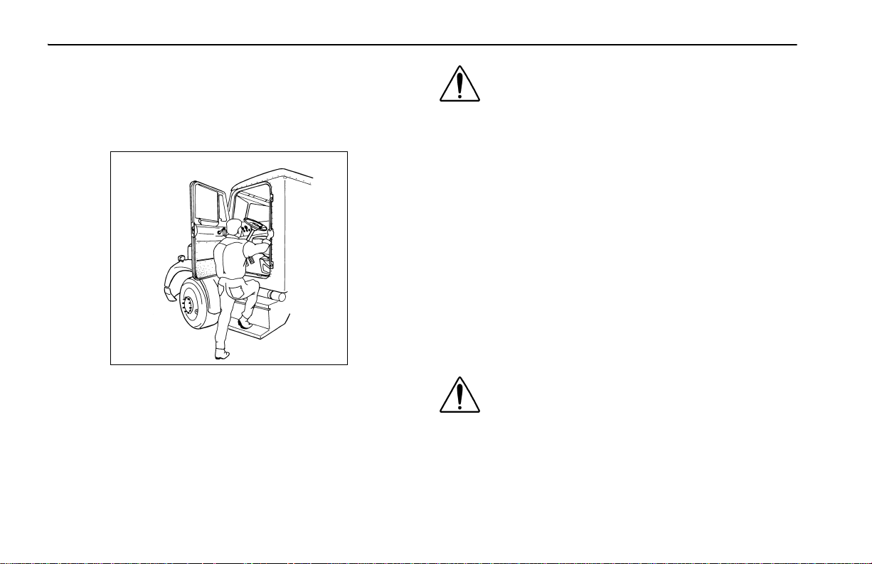
To help avoid personal injury due to a slip or fall:
• Use three points of contact (two feet, one hand or one
foot, two hands) to grip the steps or handholds whenev er
possible and look where you are going.
02611
• Use even more care when steps and handholds (or footwear) are wet, coated with ice, snow, mud, oil, fuel, or
grease.
WARNING! Do not step on vehicle components
without antiskid surfaces or use components
not designed for entry-and-exit use. You could
fall and injure yourself if y ou step ont o a slippery
surface. For example:
•Do not step onto the surface of a fuel tank. A
fuel tank is not a step. The tank surface can get
very slippery, and you might not be able to prevent a fall. Use only the steps and handholds
provided, not chain hooks, quarter fenders, etc.
•Do not climb onto and off the deck plate—use
steps and grab handle provided. If there is no
deck plate, or if proper steps and grab handles
are not provided, do not climb onto the area
behind the cab.
•Keep steps clean. Clean any fuel, oil, or grease
off the steps before entering the cab or accessing the deck plate.
WARNING! Always reinstall the battery compartment cover (step) before entering the cab. Without the battery cover you could slip and fall,
resulting in possible injury to yourself.
– 8 – Y53-6008
Medium Duty (R10/06)
Page 11

Operating Instructions Start–Up
NOTE: Any alteration (adding bulkheads, headache
racks, tool boxes, etc.) behind the cab tha t affects
the utilization of grab handles, deck plates, or frame
access steps installed by Peterbilt should comply
with Federal Motor Carrier Safety Regulation 399.
Hood Hold Downs and Tilt
The hood is locked in its closed position by an exter nal latch
on each side. These latches serve as hold downs and keep
the hood from opening unexpectedly.
CAUTION: If you do not latch the hood securely,
it could open during operation and cause vehicle damage. Be sure to latch the hood securely
before moving the vehicle.
WARNING! A pivoting hood could hurt someone
or be damaged itself. Before opening or closing
the hood, be sure there are no people or objects
in the way.
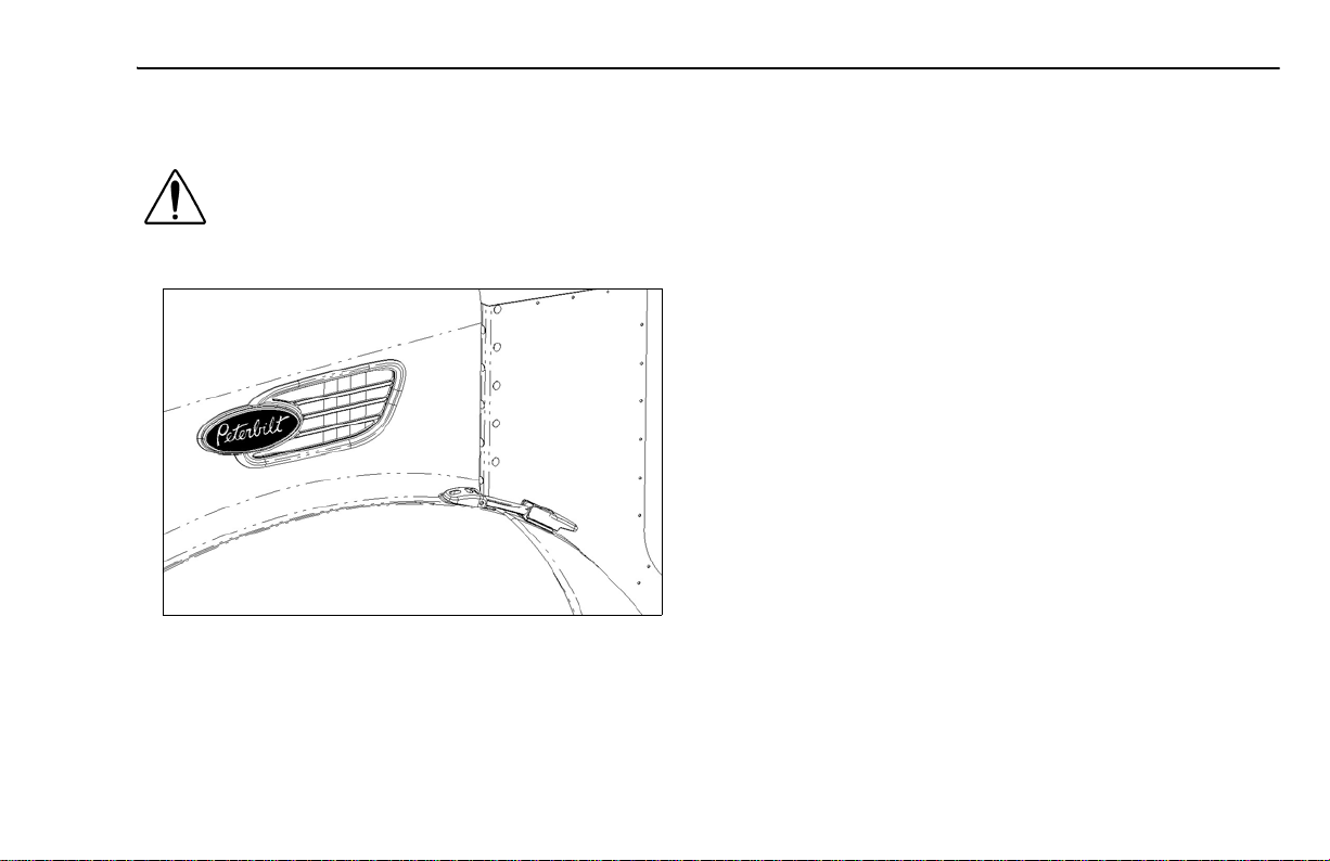
To open the hood, unlatch both of the hood hold downs.
UNLATCHED
Medium Duty
(R10/06) Y53-6008 – 9 –
Page 12

Start–Up Operating Instructions
Put one hand on the hood handle (just above the Peterbilt
emblem), one foot on the bumper, and one foot on the
ground. Tilt the hood forward until you hear it “lock”.
02609-1, -2
WARNING! If the hood falls, anyone under it
could be injured. Always make sure the lock is
engaged to keep your hood open any time anyone gets under the hood for any reason. Never
work under the hood unless the hood safety lock
is engaged.
To close the hood, you must first releas e the hood safety
lock.
WARNING! Before closing the hood, be sure the
area is clear—no people or objects are in the
way.
CAUTION: To avoid hood damage when closing
the hood, firmly squeeze the handle to release
the hold-open lock.
HOOD HOLD-OPEN
RELEASE HANDLE
– 10 – Y53-6008
Medium Duty (R10/06)
Page 13
Operating Instructions Start–Up
After lowering the hood, latch the hood closed with the hold
downs.
WARNING! If the hood is not latched securely, it
could open during operation and cause an accident. Be sure the hood is latched securely
before moving the vehicle.
LATCHED
Safe Vehicle Operation
For your safety, as well as those around you, be a responsible driver:
• If you drink, do not drive.
• Do not drive if you are tired, ill, or under emotional stress.
Much has gone into the manufacturing of your Medium Duty,
including advanced engineering techniques, rigid quality control, and demanding inspections. These manufacturing processes will be enhanced by you—the safe driver—who:
• knows and understands how to operate the vehicle and
all its controls
• maintains the vehicle properly
• uses driving skills wisely
For more information, refer to Department of Transportation
Regulation 392.7, which states that interstat e commercial
motor vehicles are not to be driven unless the driver is sure
that certain parts and accessories are in working order.
Medium Duty
(R10/06) Y53-6008 – 11 –
Page 14

Start–Up Operating Instructions
WARNING! Do not drink and drive. Your reflexes,
perceptions, and judgment can be affected by
even a small amount of alcohol. You could have
a serious—even fatal—accident if you drive after
drinking. Please do not drink and drive or ride
with a driver who’s been drinking.
•The use of alcohol, drugs, and certain medications will seriously impair perception, reactions,
and driving ability. These circumstances can
substantially increase the risk of an accident
and serious personal injury.
Vehicle Loading
Compare your vehicle's load capacity with the total load you
are carrying. If ad justments need to be made, make them—
do not drive an overloaded vehicle. If you are overloaded or
your load has shifted, your vehicle may be unsafe to drive.
WARNING! Do not exceed the specified load rating. Overloading can result in loss o f vehicle
control and serious personal injury, either by
causing component failures or by affecting vehicle handling. Exceeding load ratings can also
shorten the service life of the vehicle.
•The components of your vehicle are designed
to provide satisfactory service if the vehicle is
not loaded in excess of either the gross vehicle
weight rating (GVWR), or the maximum front an d
rear gross axle weight ratings (GAWRs). (Axle
weight ratings are listed on the driver's door
edge.)
Here are some definitions of weight you should know:
GVWR:
MAXIMUM WEIGHT your vehicle is allowed to carry, including the weight of the empty vehicle, loading platform, occupants, fuel, and any load. Never exceed the GVWR of your
vehicle.
GCW:
Weight (GCW), of your vehicle and its load: tractor, plus
trailer(s), plus cargo.
is the Gross Vehicle Weight Rating. This is the
is the actual combined weight, or Gross Combination
– 12 – Y53-6008
Medium Duty (R10/06)
Page 15

Operating Instructions Start–Up
GAWR: is the Gross Axle Weight Rating. This is the total
weight that one axle is designed to transmit to the ground.
You will find this number listed on the driver's door edge.
Load Distribution: be sure any load you carry is distributed
so that no axle has to support more than its GAWR.
WARNING! An unevenly distributed load or a
load too heavy over one axle can affect the braking and handling of your vehicle, which could
result in an accident. Even if your load is under
the legal limits, be sure it is distributed evenly.
Emergency Equipment
It is good practice to carry an emergency equipment kit in
your vehicle. One da y, if you hav e a roadside emergency, you
will be glad the following items are with you:
• window scraper
• snow brush
• container or bag of sand or salt
• emergency light
•small shovel
• first aid kit
• fire extinguisher
Driver's Check List
To keep your Medium Duty in top shape and maintain a high
level of safety for you, your passengers, and your load, make
a thorough inspection every day before you drive. You will
save maintenance time later, and the safety checks could
help prevent a serious accident. Please remember, too, that
the Federal law requires a pre-trip inspection and so do commercial trucking companies.
You are not expected to become a professional mechanic.
The purpose of your inspections is to find anything that might
interfere with the safe and efficient transportation of yourself,
any passengers, and your load. If you do find something
wrong and cannot fix it yourself, have an Authorized Service
Center or qualified mechanic repair your vehicle right away.
The following operations are to be perfor med by the driver.
Performing these checks and following the maintenance procedures in this manual will help keep your Medium Duty running properly.
Approaching Your Vehicle
• Check the overall appearance and condition. Are windows, mirrors, and lights clean and unobstructed?
Medium Duty
(R10/06) Y53-6008 – 13 –
Page 16

Start–Up Operating Instructions
• Check beneath the vehicle. Are th ere signs of fuel, oil, or
water leaks?
• Check for damaged, loose, or missing parts. Are there
parts showing signs of excessive wear or lack of lubrication? Have a qualified mechanic examine any questionable items and repair them without delay.
• Check your load. Is it secured properly?
Daily Checks
NOTE: The following items (Engine Compartment, Chassis and Cab, and Prestart Checks)
should be checked daily, as a minimum. They
are in addition to, not in place of, federal motor
Carrier Safety Regulations. These regulations
may be purchased by writing to:
Superintendent of Documents
U.S. Government Printing Office
Washington, DC 20402
Engine Compartment Checks — Daily
1. Engine Fluid Levels—add more if necessary.
• Engine oil
• Coolant (check while engine is cold)
• Power steering fluid level
• If your truck has hydraulic brakes, check the fluid
level in the master cylinder reservoir. See page 154
for more information.
2. Engine Belt—check tension and condition of belts. This
is important to ensure proper air compressor and engine
operation.
• Measure the belt tension at the longest span of the
belt. See page 142
ing belt tension.
NOTE: Deflection should be one belt thickness for each foot distance between the
pulley centers.
• If breaks or tears are found, the belt should be
replaced before operating the vehicle.
3. Fuel Filter/Water Separator Draining—check and drain.
Depending on the fuel storage facility, more frequent
draining may be required.
4. Windshield washer reservoir fluid level—fill if necessary.
5. Hood closed before entering cab. Is it latched properly?
Chassis and Cab Checks — Daily
Before entering the cab and operating the vehicle, check the
following equipment for proper maintenance:
for further information on check-
– 14 – Y53-6008
Medium Duty (R10/06)
Page 17

Operating Instructions Start–Up
1. Lights—do headlights, turn signals, emergency flashers,
and exterior lamps function and are they clean and
adjusted properly?
2. Windows and Mirrors—are they clean and adjusted
properly?
3. Tires and Wheels—are they inflated properly? Are all
wheel cap nuts in place and torqued properly—tighten if
necessary. Check front wheel bearing oil levels. Inspect
all tires and wheels for damage—correct if found.
4. Suspension—check for loose or missing fasteners.
Check damage to springs or other suspension parts.
5. Brake Components—check lines, linkages, chambers,
and brake operation.
6. If your truck has hydraulic brakes, check:
• the brake system for leaks
• hydraulic lines for cracks or kinks
• calipers for leaks
7. Air System—are there leaks?
• Air Tanks—drain water from all air tanks. Make sure
the drain cocks are closed. This procedure is also
required for air suspension tanks equipped with
automatic drain valves.
• See page 72
System.”
for further details on “Using the Brake
8. Steps and Handholds—check for worn surfaces and
loose or missing fasteners.
9. Fluid Tanks—check underneath the vehicle for signs of
fluid leaks. If any are found, correct before operating the
vehicle.
10. Fuel Tank Caps—are they secure?
WARNING! Diesel fuel in the presence of an ignition source (such as a cigarette) could cause an
explosion. You could be seriously injured. A
mixture of gasoline or alcohol with diesel fuel
increases this risk of explosion.
•Do not remove a fuel tank cap near an open
flame.
•Use only the fuel and/or additives recommended for your engine.
•See page 114
11. Trailer Connections (Tractor)—are they secure and the
lines clear? If they are not being used, are they stored
properly?
• Is the trailer spare wheel secure and inflated?
• Is the landing gear up and the handle secured?
12. Check the fifth wheel. Is the kingpin locked?
• Is the sliding fifth wheel locked?
for more information.
Medium Duty
(R10/06) Y53-6008 – 15 –
Page 18

Start–Up Operating Instructions
Prestart — Daily
1. Seat—adjust the seat for easy reach of controls.
2. If your vehicle is equipped with an adjustable steering
column, adjust the steering wheel to a comfortable position.
3. Mirrors—check and readjust mirrors if necessary.
4. Lights—turn ignition key to the IGN & ACC position and
check for warning lights and buzzer. Check operation of
turn signals and emergency lights.
5. Instruments—check all instruments.
6. Windshield—check operation of windshield wipers and
washers.
7. Horn—check operation of horn.
8. Check fire extinguisher charge and road emergency kit.
9. Fuel—check fuel. Is there enough fuel?
10. Seat Belts—fasten and adjust safety restraint belts
Weekly Operations
1. Battery—check battery and terminals.
2. Wheel Cap Nuts—are they all in place and torqued properly—tighten if necessary. See “
Page 173.
3. Other Controls and Wiring—check for condition and
adjustment.
4. Steering Components—check pitman arm, draglink, and
power steering hoses, etc., for loose, broken, or missing
parts.
5. Other Engine Compartment Checks
• Check condition and fastening of engine belt, hoses ,
clamps, and radiator.
• Check the air cleaner, muffler, and exhaust pipes.
Are they tight and secure?
• After Engine Warm-up
– Automatic Transmission—check fluid level in the
automatic transmission oil (if equipped).
Wheel Cap Nut Torque,”
– 16 – Y53-6008
Medium Duty (R10/06)
Page 19

Operating Instructions Start–Up
1
3
02599A
14
5
6
2
15
4
10
9
11
8
7
12
DASH INSTRUMENT PANEL
1 Headlight 6 Oil Pressure 11 Voltmeter (option)
2 Clearance Lights 7 Water Temperature 12 Air Pressure
3 Windshield Washer/Wiper 8 Speedometer 13 Transmission Temperature (option)
4 Panel Lights 9 Air Cleaner Restriction/Filter (option) 14 Warning Lamp Cluster
5 Tachometer 10 Fuel 15 Ignition Switch
13
02595-1A
Medium Duty
(R10/06) Y53-6008 – 17 –
Page 20

Instruments and Controls Operating Instructions
INSTRUMENTS AND CONTROLS
Introduction
Your Medium Duty dashboard is shown on the opposite
page.
The dash includes standard gauges and switches. Your vehicle may come with all or some of the switches and gauges
discussed here. The location of switches on the dash will
vary depending on the options ordered and how your vehicle
was configured.
For your convenience, all gauges and their corresponding
page numbers are listed here, see “
to the page listed to learn what each gauge does and how it
should be used.
Index of Gauges”. Refer
Instrument Index
Table 1 Index of Gauges
GAUGE REFERENCE PAGE
Tachometer 22
Engine Oil Pressure 25
Engine Coolant Temperature 23
Speedometer 21
Air Cleaner Restriction (option) 30
Fuel Level 28
Voltmeter (option) 29
Air System Pressure 26
Transmission Temperature (option) 29
Warning Lights and Buzzer
Many vehicle systems are linked to the instruments on your
instrument panel. Warning lights (in each instrument) may
indicate something is wrong with one of the many vehicle
systems. Check the lights frequently, and respond properly
as soon as a light or buzzer comes on.
– 18 – Y53-6008
Medium Duty (R10/06)
Page 21

Operating Instructions Instruments and Controls
WARNING LAMP MODULE
Medium Duty
HIGH
BEAM
FIFTH
WHEEL
LOAD
LIGHT
STOP
ENGINE
CHECK
ENGINE
CRUISE
CONTROL
DIFF
LOCK
SPOT
LIGHT
WAIT
TO
START
ENGINE
OIL
BRAKE
AIR
MIRROR
HEAT
LOW
WATER
WATER
FAN
ABS
VEHICLE WITH AIR BRAKES
CHECK
TRANS
OIL
!
BRAKE
MIRROR
HEAT
LOW
WATER
WATER
ENGINE
FAN
HIGH
BEAM
FIFTH
WHEEL
LOAD
LIGHT
STOP
ENGINE
CHECK
ENGINE
CRUISE
CONTROL
PARK
RANGE
SPOT
LIGHT
INHIBIT
P
VEHICLE WITH HYDRAULIC BRAKES
(R10/06) Y53-6008 – 19 –
Page 22

Instruments and Controls Operating Instructions
Self Test
When you turn on your ignition, the following warning lights
will turn on for 3 - 5 seconds, as a test to let you know they
are working.
Diff Lock Trailer ABS
Water Temp Left Turn
Mirror Heat Load Light
Brake Air (or Brake *) High Beam
Fifth Wheel Right Turn
Oil Pressure Engine Fan
ABS Park *
* Vehicle with hydraulic brakes only
WARNING! Do not ignore a warning light or
buzzer. These signals tell you some thing is
wrong with your vehicle. It could be a failure in an
important system, such as the brakes, which
could lead to an accident. Have the appropriate
system checked immediately.
The buzzer will sound continuously as long as:
• Engine temperature is above the specified range
• Air pressure to the service brakes is low
• Engine oil pressure is low
• There is a problem in the hydraulic brake system
If the buzzer sounds while driving, or if a light comes on, do
the following:
1. Slow down carefully.
2. Move a safe distance off the road and stop.
3. Set the parking brake. (See Pages 68
mission shifting and parking brake information.)
4. If the engine is overheating do not turn it off, see page
23; otherwise, for other conditions turn the engine OFF.
5. Turn on the emergency flasher and use other warning
devices to alert other motorists.
and 74 for trans-
– 20 – Y53-6008
Medium Duty (R10/06)
Page 23

Operating Instructions Instruments and Controls
WARNING! Do not operate the vehicle if the
BRAKE warning lamp illuminates or the buzzer
sounds. The vehicle should not be oper ated until
the system is repaired. Failure to respond to a
brake warning (lamp or buzzer) could result in an
accident and/or severe injury.
Speedometer and Odometer
The speedometer indicates the vehicle speed in miles per
hour (MPH) and in kilometers per hour (km/h).
The odometer records the distance traveled by the vehicle,
either in miles or kilometers, depending on which unit is
installed in the vehicle.
Speedometer (MPH-km/h)
02587
Medium Duty
(R10/06) Y53-6008 – 21 –
Page 24

Instruments and Controls Operating Instructions
Tachometer
The vehicle's tachometer measures the engine speed in revolutions–per–minute (rpm). Watching the tachometer is
important to driving efficiently. It will let you match driving
speed and gear selection to the operating range of your
engine. If the engine speed gets too high, you can select a
higher gear to lower the rpm's. If the engine speed drops too
low, you can select a lower gear to raise the rpms. See page
99 for further instructions on driving techniques and using the
HOURMETER
(OPTION)
Tachometer
02586
tachometer.
• To avoid engine damage, do not let the pointer exceed
maximum governed speed.
• When driving downhill, shift to a lower gear and use the
service brake, keeping the engine speed below the maximum governed speed.
The hour meter (option) records the time in hours the engine
is operating.
– 22 – Y53-6008
Medium Duty (R10/06)
Page 25

Operating Instructions Instruments and Controls
Coolant (Water) Temperature Gauge
The water temperature gauge shows the temperature of the
engine coolant. Under normal operating conditions the water
temperature gauge should register between 165 and 205°F
(74 and 90°C). Under certain conditions, somewhat higher
temperatures may be acceptable. The maximum allowable
temperature is 210°F (99°C) with the cooling system pressurized, except for cer tain special engines. Check the engine
manual to be sure.
02580
Water Temperature Gauge
Engine Overheating
The cooling system may ov erheat if the coolant level is below
normal or if there is sudden loss of coolant, such as a split
hose. The system may also temporarily overheat during
severe operating conditions such as:
• Climbing a long hill on a hot day
• Stopping after high–speed driving
If the Engine Coolant Temperature (“WATER”) warning light
comes on and the audible alarm sounds showing an overheat condition, or if you have an y other re ason to suspect the
engine may be overheating, DON'T TURN OFF THE
ENGINE unless the “LOW WATER” warning light also comes
on, indicating a loss of coolant. Instead, follow these steps:
A. Reduce engine speed or stop. When stopped, place the
transmission in Neutral and set the parking brake. See
Pages 68
and 74 for transmission shifting and parking
brake information.
B. Check to ensure that the oil pressure gauge reads nor-
mal.
C. Increase the engine speed to about one–half of full oper-
ating speed, or 1100 to 1200 rpm, maximum.
Medium Duty
(R10/06) Y53-6008 – 23 –
Page 26

Instruments and Controls Operating Instructions
D . Return the engine speed to normal idle after two or three
minutes.
E. Monitor the engine temperature. After the temperature
returns to normal, allow the engine to idle 3 to 5 minutes
before shutting it off. This allows the engine to cool gradually and uniformly.
• If the overheating came from severe operating conditions, the temperature should have cooled by this
time.
FILL
02604
Coolant Expansion Tank
F. Check the level of coolant in the coolant expansion tank
(engine compartment, right side.)
WARNING! Removing the radiator fill cap while
the engine is hot can be dangerous. Never
remove the caps of the expansion tank while the
engine is still hot; you could be badly burned.
•Scalding steam and fluid under pressure may
escape and cause serious personal injuries.
•Wait until the coolant temperature is below
122°F (50°C).
•Protect your face, hands, and arms by covering
the cap with a large, thick rag to protect against
escaping fluid and steam.
WARNING! Carefully and slowly turn cap one
turn to allow excess pressure to escape, then
push down and turn for final removal.
G. See page 143
for instructions on checking and filling the
coolant expansion tank.
– 24 – Y53-6008
Medium Duty (R10/06)
Page 27

Operating Instructions Instruments and Controls
WARNING! To reduce the chance of personal
injury and/or vehicle damage due to engine
overheating, never leave the engine idling without an alert driver present. If the engine should
overheat, as indicated by the engine coolant
temperature light, immediate action is required
to correct the condition. Continued unattended
operation of the engine, even for a short time,
may result in serious engine damage or a fire.
For further details on engine operation, see the Engine Operation and Maintenance Manual in the glove compartment of
your vehicle.
Engine Oil Pressure Gauge
It is important to maintain oil p ressure within acceptable limits. If oil pressure drops below the minimum psi a Red Warning Lamp on the oil pressure gauge and the Stop Engine
Warning Lamp will come ON.
For further information on engine oil and normal operating
pressures, see the Engine Operation and Maintenance Man-
ual.
Medium Duty
(R10/06) Y53-6008 – 25 –
02585
Engine Oil Pressure Gauge
CAUTION: Continuing to operate your vehicle
with insufficient oil pressure will cause serious
engine damage.
• If the oil pressure fails to rise within 10 seconds after the
engine starts, stop the engine and determine the cause.
• Check the engine manufacturer's manual for the correct
oil pressure ranges for your vehic le's engine.
• If the oil pressure suddenly drops, or the audible alarm
and engine oil pressure warning light come on while driving, do the following:
1. Slow down carefully.
2. Move a safe distance off the road and stop.
Page 28

Instruments and Controls Operating Instructions
3. Place the transmission in park and set the parking
brake. (See Pages 68
and 74 for transmission
shifting and parking brake information.)
4. Turn OFF the engine.
5. Turn ON the emergency flasher and use other
FRONT
SECONDARY
SERVICE
CIRCUIT
(WHITE)
warning devices to alert other motorists.
6. Wait a few minutes to allow oil to drain into the
engine oil pan, and then check the oil level. (See
page 139
7. Add oil if necessary. If the problem persists, contact an Authorized Service Center.
For further information on operating your engine properly,
see page 58
for details on checking oil level.)
.
02581
Dual Air Pressure Gauge (Air Reservoir)
REAR
PRIMARY
SERVICE
CIRCUIT
(ORANGE)
If the pressure in either or both circuits is too low for normal
Dual Air Pressure Gauge (Air Reservoir)
The dual air pressure gauge indicates the amount of air pressure in the brake system in pounds per square inch (psi). The
WHITE pointer shows the front (secondary service) reservoir
air pressure, and the ORANGE pointer indicates pressure in
the rear (primary service) reservoir.
brake operation (below 64 psi), a warning light in the panel
will glow and the audible alarm will sound.
WARNING! If the light and alarm do not turn off
at start-up, do not try to drive the vehicle until
the problem is found and fixed.
– 26 – Y53-6008
Medium Duty (R10/06)
Page 29

Operating Instructions Instruments and Controls
WARNING! If the air pressure falls below 60 psi
(414 kPa) the spring brakes may stop the vehicle
abruptly, which could result in an accident and/
or injuries. Observe the warning light in the
panel. If it comes on, do not continue to drive the
vehicle until it has been properly repaired or serviced.
WARNING! The air pressure warning light and
the audible alarm indicate a dangerous situation: there is not enough air pressure in the reservoirs for repeated braking and the brake
system has failed. Without the use of your service brakes, your spring brakes could suddenly
apply. This could cause a wheel lock-up, loss of
control, or over-take by following vehicles. You
could be in an accident and severely injured.
•Bring the vehicle to a safe stop right awa y, while
you still have control of the vehicle.
Air Loss Emergency Procedure
1. Slow down carefully.
2. Move a safe distance off the road and stop.
3. Place the transmission in park and set the parking brake.
(See Pages 68
ing brake information.)
4. Turn OFF the engine.
5. Turn ON the emergency flasher (See “
Flasher Switch” on page 55) and use other warning
devices to alert other motorists.
and 74 for transmission shifting and park-
Emergency
Medium Duty
(R10/06) Y53-6008 – 27 –
Page 30

Instruments and Controls Operating Instructions
Fuel Gauge
The fuel gauge shows the approximate amount of fuel in the
fuel tanks. Besides empty and full, the gauge also indicates
1/4, 1/2 and 3/4 of total fuel capacity.
02584
Fuel Gauge
Your truck has one main fuel tank and up to four optional
tanks. The fuel gauge shows the total amount of fuel. It is a
good idea to keep fuel tanks at least half–full; otherwise,
water that condenses in an empty tank will contaminate the
fuel and could damage the engine.
WARNING! Do not carry additional fuel containers in your vehicle. Fuel container s, eit her full or
empty, may leak, explode, and cause or feed a
fire. Do not carry extra fuel containe rs, even
empty ones are dangerous.
WARNING! Do not remove a fuel tank cap near
an open flame. Hot fuel vapors are combustible
and can cause an explosion or fire resulting in
injury or death.
See page 114
for more information.
– 28 – Y53-6008
Medium Duty (R10/06)
Page 31

Operating Instructions Instruments and Controls
Voltmeter (option)
The voltmeter shows the voltage your vehicle's electrical system is putting out. Normally, it should show 10 to 16 volts. If
voltage drops, have the electrical system checked.
02582
Voltmeter
Transmission Temperature Gauge (option)
Your vehicle may be equipped with a transmission temperature gauge. It indicates the temperature of the oil in your
transmission. Watch this gauge to know when your tr ansmission is overheating. If it is, have it checked by an Authorized
Service Center.
02579
Transmission Temperature Gauge
CAUTION: Maximum allowable transmission
temperature may vary, depending upon your
transmission and type of lubricant. Check your
transmission Owner's Manual.
Medium Duty
(R10/06) Y53-6008 – 29 –
Page 32

Instruments and Controls Operating Instructions
CAUTION: Do not continue to operate with the
Air Filter Restriction Gauge reading 25 in. (start
of red area). It could lead to damage to the
RED
CAUTION
AREA
engine. Inspect the filter and replace if necessary.
Holes in the paper element render an air cleaner useless and
may cause the Air Filter Restriction Gauge to give a false
reading, even if the element is clogged. Replace the element
if it is damaged. See page 167
for information on Air Filter
Replacement.
02583
Air Filter Restriction Indicator
Headlight Switch
The headlights are controlled by a toggle
Air Filter Restriction Indicator (option)
This gauge indicates the condition of the engine air cleaner
and is measured by inches of water . A clean filter should register 7 in. of water and a filter whose life is over will register
approximately 25 in.
For High Beam operation see page 54
switch on the left instrument panel. See
page 17
. When the headlights are ON, the
dash lights, side, and tail lamps are also
on.
.
– 30 – Y53-6008
Medium Duty (R10/06)
Page 33

Operating Instructions Instruments and Controls
Daytime Running Lights (option)
On vehicles equipped with the Daytime Running Light (DRL)
system, the low beam headlights are turned ON automatically at reduced brightness (to conserve headlamp life).
Three controls (or conditions) will affect whether the system
is ON or OFF:
• headlight switch
• engine on
• parking brake
If the headlight switch is turned OFF, the DRL system
engages automatically after the engine starts and you
release the parking brake. If the headlight switch is ON, the
DRL system is overridden, and headlights operate normally.
WARNING! Do not use daytime running lights
(DRL) during periods of darkness or reduced
visibility. Do not use DRL as a substitute for
headlights or other lights during operations that
require lighting of your vehicle. Doing so could
lead to an injury accident.
Panel Lights
The Panel Lights knob lets you vary the
brightness of your instrument panel lights.
The knob is located on the left instrument
panel. See page 17
.
To Operate the Panel Lights:
Turn on either the headlights, clearance lights, or fog/driving
lights.
To brighten the instrument panel lights, tur n the knob clockwise (to the right).
To dim the instrument lights or to turn them off, turn the knob
counterclockwise (to the left).
ID and Clearance Lights
A toggle switch controls the amber lights on
top of your cab , plus any additional lights that
were installed on the front, sides, and rear of
your vehicle. The switch is located on the left instrument
panel, and is labeled CL LPS. See page 17
.
Medium Duty
(R10/06) Y53-6008 – 31 –
Page 34

Instruments and Controls Operating Instructions
Windshield Wipers/Washer
NOTE: The ignition key must be turned to ACC or
IGN & ACC for the wiper/washer switch to operate.
A five-position windshield wiper switch controls the wipers
and washer. To turn ON the wipers, turn the knob clockwise.
• For intermittent operation turn to the 1st and 2nd positions; for continuous operation advance to the 3rd and
4th positions.
• The final option activates the washer cycle. To wash the
windshield, push knob IN and release. Hold knob IN to
extend washing cycle. After one to three wipes (depending on how long you hold the switch in) the wipers will
shut off automatically.
The windshield washer tank is located inside the engine
compartment below the radiator expansion tank. See
“
Washer Reservoir” on page 201. Check the windshield
washing fluid level weekly. If necessary, fill to top.
CAUTION: If the electric pump is operated for a
long period (more than 15 seconds) with a dry
reservoir, the pump rotor may be damaged.
PUSH IN
FOR
WASHER
Windshield wipers/washer switch
POSITION MODE
0OFF
1 Intermittent Range: long delay
2 Intermittent Range: Short delay
3 Low Speed
4 High Speed
Wiper/washer (push in)
0
1
2
3
4
– 32 – Y53-6008
Medium Duty (R10/06)
Page 35

Operating Instructions Instruments and Controls
WARNING! Do not drive with worn or dirty wiper
blades. They can reduce visibility, making driving hazardous. Clean the blades regularly to
remove road film and wax build-up. Use an alcohol-based cleaning solution and a lint-free cloth,
and wipe along the blades.
WINDSHIELD
WASHER FLUID
TANK
02391
Windshield Washer Fluid Tank
Clean all inside and outside windows regularly. Use an alcohol-based cleaning solution and wipe dry with e ither a lintfree or a chamois cloth. Avoid running the wiper blades over
a dry windshield to prevent scratching the glass. Spray on
washer fluid first. A scratched windshield will reduce visibility.
Ignition Key Switch
The engine ignition key switch (located to the left of the steering column) has four positions: ACC (Accessories), OFF, IGN
& ACC, and IGN & START.
OFF: In this position all accessories are OFF (except those
listed below) and you can remove the key.
• The following lights and accessories have power when
the key is in the OFF position:
- brake lights - marker lamps
- cigarette lighter - headlights
- tail lights - radio station memory
- horn - instrument lights
- emergency hazard flasher
- dome and courtesy lamps (on doors)
- auxiliary Power/Body or Trailer
NOTE: In the OFF position, fuel is cut off by a solenoid valve located on the left side of the engine,
near the ejection pump.
ACC (Accessory): With the key in this position you can play
the radio, defrost mirrors (if equipped with mirror heat) or use
other accessories.
Medium Duty
(R10/06) Y53-6008 – 33 –
Page 36

Instruments and Controls Operating Instructions
IGN & ACC: In this position, all circuits are energized. Panel
warning lights will light and the buzzer will sound until (1) the
engine is started, (2) nor mal oil operating pressure is
reached, and (3) air brake system pressure is above 64 psi
(441 kPa). In this position, the ignition key cannot be
removed.
IGN & START: Turn the key to this position to start your
engine: it energizes the starter and retracts the solenoid
valve to allow fuel supply to the engine. See page 59
for
details on starting the engine.
Parking Brake
Before you leave the cab, apply all parking brakes.
- for vehicles with air brakes:
1. Apply all parking brakes. Pull out the Yellow Parking
Brake Control knob (1) located on the dash. In tractors,
the Red (octagon-shaped) Trailer Air Supply Control
knob (2) will automatically pop out.
38//
72$33/<
3$5.,1*
%5$.(
386+72
5(/($6(
02391-1
Full Truck Parking Brake Valve
WARNING! Do not leave the cab without applying the parking brake. The truck could roll and
cause an injury accident. Always apply the parking brake before you leave the cab.
– 34 – Y53-6008
Medium Duty (R10/06)
Page 37

Operating Instructions Instruments and Controls
Using the Brake System” on page 72 for more informa-
See “
(2) Trailer Air Supply
Control (Red)
(1) Parking Brake Control
(Yellow)
tion.
- for vehicles with hydraulic brakes:
The parking brake consists of a driveline drum brake actuated by a lever and cable. The hand lever, mounted on the
vehicle's cab floor, pulls or releases the cable controlling the
brake. Pulling upward on the parking brake lever pulls the
02394
Combination (Tractor/Trailer) Parking Brake Control Valves
cable and expands the driveline brak e shoes outward against
the driveline brake drum.
The driveline brake is disengaged by pushing the handle
2. Shift the transmission into its PARK position. (See Pages
and 74 for transmission shifting and parking brake
68
information.)
3. Turn the key to OFF.
4. Remove the key.
downward to its lowest position.
NOTE: Failure to fully release the parking brake can
cause the brakes to overheat.
CAUTION: Unless it is an emergency, do not pull
upward on the parking brake lever while the
WARNING! Do not pull out the parking brake
valve while the vehicle is moving. Stopping with
the parking brake controls can cause a sudden
wheel lock-up, loss of control, or over-take by
vehicle is moving. Attempting to stop with the
parking brake could cause damage to the drive-
line, transmission, or the parking brake mecha-
nism itself.
following vehicles. You could be severely
injured.
Medium Duty
(R10/06) Y53-6008 – 35 –
Page 38

Instruments and Controls Operating Instructions
Using the Parking Brake
1. Come to a complete stop.
PARKING BRAKE LEVER
ENGAGE
DISENGAGE
2. Apply the parking brake. Pull upward on the parking
brake lever until it reaches an over (top) center position. (The PARK light on the dash will come on.)
NOTE: Ensure the lever is over center. The light will
come on prior to brake being fully applied.
CONTROL
STOP
ENGINE
CHECK
ENGINE
CRUISE
P
PARK
SPOT
LIGHT
PARKING BRAKE INDICATOR
3. Shift the transmission into NEUTRAL position:
4. Turn the key OFF.
5. Remove the key.
6. If you are parked on a grade, always block the
wheels.
– 36 – Y53-6008
Medium Duty (R10/06)
Page 39

Operating Instructions Instruments and Controls
Cruise Control Switch
02901
WARNING! Do not operate the cruise control
when operating on road surfaces with poor
traction (wet, icy, or snow covered roads) or in
heavy traffic. Accelerations caused by the normal operation of the cruise control could cause
you to lose control of the vehicle resulting in an
injury accident.
The master switch turns the cruise control ON or OFF.
The second switch allows you to SET the desired speed
or RESUME the desired speed after the cruise control
function has been interrupted.
See page 65 for instructions on how to use the cruise control.
Hand Throttle Control
Your vehicle may be equipped with a hand throttle. It is
located on the floor, to the left of the driver's seat. It can be
especially helpful in cold weather to keep your engine running above idle speed when you leav e the v ehicle briefly. See
page 64
for more information on idling your engine safely.
WARNING! Do not use the hand throttle control
for cruise control or to control your road speed.
It could cause an accident and you could be
seriously injured. Always disengage the hand
throttle before driving the vehicle.
Medium Duty
(R10/06) Y53-6008 – 37 –
Page 40

Heating and Air Conditioning Operating Instructions
)5(6+
5(&,5&
$&
212))
HEATING AND AIR CONDITIONING
Introduction
WARNING! Do not drive with your visibility
reduced by fog, condensation, or frost on the
windshield. Your view may be obscured, which
could result in an injury accident. For clear visibility and safe driving it is extremely important
for you to follow the instructions on the use of
the ventilation/heating and defogging/defrosting
system. If in doubt, consult your dealer. Maximum heating output and fast defrosting can be
obtained only after the engine has reached operating temperature.
Internal air circulation control is provided by three sets of
outlets:
• Front outlets on the dashboard panel, with directional
louvers
• Floor outlets under the dashboard
• Window defrost vents on the dashboard
A
E
B
Heater and Air Conditioner Controls
WARNING! Excessive heat may cause the pressurized components of the air conditioning system to explode. Never weld, solder, steam clean,
or use a blow torch near any part of the air conditioning system.
•If a refrigerant leak develops in the presence of
excessive heat or an open flame, hazardous
gases may be generated. These gases may
cause unconsciousness or death. If you become
C
D
02593
– 38 – Y53-6008
Medium Duty (R10/06)
Page 41

Operating Instructions Heating and Air Conditioning
aware of a refrigerant leak on your vehic le, have y our
system serviced immediately and observe the following precautions:
– Stay away from the hot engine until the exhaust
manifold has cooled.
– Do not permit any open flame in the area. Even a
match or a cigarette lighter may generate a hazardous quantity of poisonous gas.
– Do not smoke in the area. Inhaling gaseous
refrigerant through a cigarette may cause violent
illness.
WARNING! Ne ver idle y our vehicle for prolonged
periods of time if you sense that exhaust fumes
are entering the cab. Investigate the cause of the
fumes and correct it as soon as possible. If the
vehicle must be driven under these conditions,
drive only with the windows slightly open. Failure to repair the source of the exhaust fumes
may lead to personal harm.
NOTE: Keep the engine exhaust system and the
vehicle’s cab ventilation system properly maintained. It is recommended that the vehicle’s
exhaust system and cab be inspected:
• By a competent technician every 15,000 miles.
• Whenever a change is noticed in the sound of the
exhaust system.
• Whenever the exhaust system, underbody, cab or
sleeper is damaged.
NOTE: To allow for proper operations of the vehicle
ventilation system, keep the inlet grille at the base
of the windshield clear of snow, ice, leaves, and
other obstructions at all times.
WARNING! Do not stay in the vehicle with the
engine running or idling for more than 10 minutes with the vehicle’s Heater and A/C ventilation system in RECIRC or at LOW FAN SPEED.
Even with the ventilation system ON, running
the engine while parked or stopped for prolonged periods of time is not recommended.
Controls
The heater and air conditioning control unit is mounted in the
center dash console, below the radio. The standard control
unit has four controls to regulate air flow and temperature in
Medium Duty
(R10/06) Y53-6008 – 39 –
Page 42

Heating and Air Conditioning Operating Instructions
the cab: fan speed switch (A), air directional control switch
(B), air temperature switch (C), and air circulating mode
switch (D). With optional air conditioning, a fifth switch (E) is
used.
Fan Speed Control
The fan speed rotary switch (A) allows you to select one of
four blower speeds (1-4).
Air Direction Control
The air direction rotary switch (B) controls the air movement
within the cab. Fiv e modes direct the air flo w to the three sets
of air outlets: front panel, floor, and window defrost:
1.Front Panel only
2.Panel and Floor (Bi-level)
3.Floor only
4.Defrost and Floor (Bi-level)
5.Defrost only
Temperature Control
The temperature rotary switch (C) allows you to adjust and
maintain a comfortable internal cab temperature.
Air Circulation Control
The air circulation rocker switch (D) allows you to select
FRESH air from outside the cab or recirculate (RECIRC) air
from within the cab.
Air Conditioner Control
The optional air conditioner is engaged with this rocker
switch (E).
Heating
To heat the cab: select the desired air direction and circulat ing mode (B and D) and set the temperature knob (C) to hot
(red position on the control). Adjust the fan speed (A) as
desired.
– 40 – Y53-6008
Medium Duty (R10/06)
Page 43

Operating Instructions Heating and Air Conditioning
CAUTION: During extreme cold weather, do not
blow hot air onto cold windshields. This could
crack the glass. Turn the air direction lever to
Defrost and adjust the fan speed accordingly
while the engine warms. If the engine is already
warm, move the temperature selector to Cool,
then gradually increase the temperature when
you see that the windshield is starting to warm
up.
Defogging
NOTE: The air conditioning system is active when
the Defrost mode is selected.
To defog the windshield: select air direction mode 4 or 5 and
turn the fan speed switch (A) to high. Set the temperature
knob (C) to hot (red position on the control). The air conditioner (if equipped) is automatically activated to remov e moisture from the cab. After the windshield is clear, adjust the
controls as desired.
HEAT ING A/C CONTROL
CONTROLS
Fan Speed (A) High (4) Adjust High (4) Adjust High (4) Adjust
Air Direction
Mode (B) Panel
Temperature (C) Warm Adjust Cool Adjust Warm Adjust
Air Circulation
Mode (D)
Air Conditioner -
AC (E)
HEATING COOLING DEFOGGING
MAX NML MAX NML MAX NML
Panel
or BiLevel
(2)
Adjust Adjust
(1)
Recirc Fresh Record Fresh Recirc Fresh
OFF OFF ON ON — —
Defrost
(5)
Defrost
or Bi-
Level (4)
Cooling
To cool the cab: turn on the air cond itioner (if equipped)
(switch E), set the temperature knob (C) to cool (blue side),
and the fan (A) to high until the cab becomes cool—adjust as
desired.
For Efficient Cooling:
1. Ensure all heater/air conditioner controls are off.
2. Start the engine. Allow time for warm–up.
Medium Duty
(R10/06) Y53-6008 – 41 –
Page 44

Heating and Air Conditioning Operating Instructions
NOTE: A cold compressor can cause refrigerant to
liquefy and warp the valve plates or cause a hydr aulic lock. Warm the engine before starting the air conditioner.
3. Set the air conditioner for maximum cooling.
4. Close all windows.
5. Idle the engine between 1000 and 1500 rpm and turn the
fan switch to High.
6. After the cab temperature cools to a comfortable level,
adjust the fan speed and other controls to keep the
desired condition.
If the air conditioner does not cool the air, have the
unit checked at an Authorized Service Center.
NOTE: When the air conditioner isn't in regular use,
operate it for at least 15 minutes at least once a
month or every 5,000 miles (8,000 km), whichever
comes first. This will lubricate the seals in the air
conditioning system.
– 42 – Y53-6008
Medium Duty (R10/06)
Page 45

Operating Instructions Accessories
ACCESSORIES
Radio
As an option, your vehicle has either an AM/FM Stereo
Receiver or an AM/FM Stereo/Cassette Player.
For instructions on how to operate your particular radio, see
the manufacturer's Radio Operating Instructions in the glove
compartment.
Cigarette Lighter
NOTE: The cigarette lighter will operate with the
ignition key in either the OFF, ACC (accessory), or
IGN/ACC position.
To operate, push in on the knob end of the lighter. After a f e w
moments, the lighter will automatically pop out, glowing hot
and ready to use. After use, insert the lighter back into the
socket without pushing all the way in.
The socket of the cigarette lighter may be used to operate 12
volt, 15 ampere appliances, such as a hand spotlight or small
vacuum cleaner.
WARNING! Do not exceed the voltage/amperage
capacity of the cigarette lighter. It could re sult i n
a fire. Follow all warnings and instructions in the
operator's manual for the appliance you are
using.
Ashtray
To open, pull on the upper side of the panel. To close, push
against the panel.
WARNING! Do not place paper or other combustible substances in an ashtray. It could cause a
fire. Keep all burnable materials besides smoking materials, out of the ashtray.
Air Operated Horn (Option)
Your Medium Duty may be equipped with an air horn. To
operate, pull on the lanyard extending from the overhead
header panel. Your vehicle also has an electric horn. See
page 56
.
Medium Duty
(R10/06) Y53-6008 – 43 –
Page 46

Accessories Operating Instructions
Glove Compartment
A glove compartment is provided to store important docu ments, the vehicle literature set (including this Operator's
Manual) and other related materials. You can open it by
pushing the knob on the front.
• To close, push the cover up and press to latch it.
• You can lock and unlock the glove compartment door
with your ignition key; turn it clockwise to lock and counterclockwise to unlock.
WARNING! Do not drive with the glove compartment open, it can be dangerous. In an accident
or sudden stop, you or a passenger could be
thrown against the cover and be injured. To
reduce the risk of personal injury during an accident or sudden stop, keep the glove compartment closed when the vehicle is in motion.
WARNING! Do not carry loose objects in your
cab, it can be dangerous. In a sudden stop, or
even going over a bump in the road, they could
fly through the air and strike y ou or a passenger.
You could be injured or even killed. Secure all
loose objects in the cab before moving the vehicle.
Dome Light
The dome light is automatically activated when you open the
door. To turn the dome light on when you are inside the cab,
turn the headlight switch counter–clockwise until it clicks and
the light comes on.
– 44 – Y53-6008
Medium Duty (R10/06)
Page 47

Operating Instructions Seats
SEATS
Introduction
This section covers the operation and safe use of your
Medium Duty seats. For further information on features and
adjustment of the seat, see the manufacturer's literature
included with the vehicle.
Seat Adjustment
WARNING! Do not adjust the driver's seat while
the vehicle is moving. A sudden or unexpected
seat movement can cause the driver to lose control of the vehicle. Make all adjustments to the
seat while the vehicle is stopped.
• After adjusting the seat and before driving off,
always check to be sure that the seat is firmly
latched in position.
Standard Driver's Seat
The standard driver's seat can be adjusted forward and rearward. These movements are each controlled by levers
located on the FRONT of the seat.
Driver's Seat with Air Suspension (Option)
WARNING! Before driving or riding in the vehicle, be sure that there is adequate head clearance at maximum upward travel of seat. Serious
injury may occur if head clearance is not adequate.
CHUGGER-SNUBBER
LOCK-OUT FEATURE
Move handle down to
unlock
FRONT CUSHION
HEIGHT
Lift and pull forward
to raise position
FORE & AFT ISOLATOR
Move to left and slide
seat to desired position
BACKREST TILT
Rotate knob for
infinite selection of
SEAT RIDE HEIGHT
LUMBAR ADJUSTMENT
Push switch up to inflate
Push down to deflate
Peterbilt Ultraride II Highback Air Seat
settings
03017
Medium Duty
(R10/06) Y53-6008 – 45 –
Page 48

Seats Operating Instructions
Safety Restraint Belts
The right and left seats are equipped with 3-point lap/shoulder belts; the center seat has a 2-point seat belt. Safety belts
have proven to be the single most effective means available
for reducing the potential for either serious injury or death in
motor vehicle accidents. Therefore, read and follow these
instructions and always observe user warnings pertaining to
safety belts.
0917A
Unbelted Person in Crash
WARNING! Do not drive vehicle without your
seat belt and your riders’ belts fastened. Riding
without a safety belt which is properly fastened
can lead to increased injury or death in an accident. Unbelted riders could be thrown into the
windshield or other parts of the cab or could be
thrown out of the cab. They could strike another
person. Injuries can be much worse when riders
are unbelted. Always fasten your seat belt and
be sure anyone riding with you does the same.
Lap/Shoulder Belt
The combination lap-shoulder belt is equipped with a locking
mechanism. The system adjusts automatically to a person's
size and movements as long as the pull on the belt is slow.
Hard braking or a collision locks the belt. The belt will also
lock when driving up or down a steep hill or in a sharp curve.
To fasten the belt:
1. Grasp the belt tongue.
2. Pull the belt in a continuous slow motion across your
chest and lap.
– 46 – Y53-6008
Medium Duty (R10/06)
Page 49

Operating Instructions Seats
• Belts should fit snugly across the pelvis and chest.
Make sure any slack is wound up on the retractor.
To unfasten the belt:
Push in the release button on the buckle. The belt will spring
out of the buckle.
• To release a locked belt, lean back to take the body pressure off of the belt.
• To store a lap-shoulder belt, allow the belt to wind up on
the retractor by guiding the belt tongue until the belt
comes to a stop.
01888
Proper Safety Belt Adjustment
3. Insert the belt tongue into the buckle on the inboard side
of the seat.
4. Push down until the tongue locks securely (with an audible click). Pull on the belt to check for proper fastening.
• Pull the shoulder section to make sure the belt fits
snugly across the chest.
• The shoulder belt must be positioned over the shoulder—it must never rest against the neck.
Medium Duty
(R10/06) Y53-6008 – 47 –
Your combination lap-shoulder belt may need adjustment.
Adjust safety belts properly.
• The lap belt should be worn as low and tight on the hips
as possible. Make sure any slack is taken up by the belt
mechanism.
• The shoulder belt should fit snugly across your body. It
should be positioned midway over the shoulder (nearer
to the door); it should never rest against your neck.
Page 50

Seats Operating Instructions
Lap Belt Shoulder Belt
Too High
on Hips
Correct
Safety Restraint Belts
Incorrect
Correct (over arm)
• Be sure, also, that your belt is not too loose. A loose belt
could allow you to slide under it in an accident, and that
could bring the belt up around your abdomen.
• Do not twist the belt in the process of putting it on. A
twisted belt will not work as well to protect you.
WARNING! Always wear your seat belt low over
your pelvic bones.
– 48 – Y53-6008
Incorrect (under arm)
Incorrect (twisted)
• You can be seriously injured if your belt is buckled
too high. In a crash, it would apply force to your
abdomen, not your pelvic bones. This can result in
serious internal injuries.
• Do not drive with your seat belt loose. A seat belt
that is too loose can allow you to fall too far forward,
possibly causing head and neck injuries. You could
strike the wheel or the windshield. Adjust your belt
so that there is no more than 1 in. (25mm) of slack.
Medium Duty (R10/06)
Page 51

Operating Instructions Seats
WARNING! Do not wear the shoulder belt under
your arm or otherwise out of position. In a crash
your body would move too far forward, increasing the chance of head and neck injury. Also, the
belt would apply too much force to the ribs,
which are not as strong as your shoulder bones,
and could cause you to suffer internal injuries.
Wear the shoulder belt over your shoulder (see
Safety Restraint Belts” on page 46).
“
WARNING! Do not twist the belt in the process of
putting it on. A twisted belt will not work as well
to protect you. In a crash, the full width of the
belt would not be protecting you. A twisted belt
could cut into your body and cause serious injuries. Straighten the belt before buckling it. If you
are unable to wear it without twisting it, have
your dealer or service person repair it as soon
as possible.
Safety Restraint Tips
NOTE: Per FMCSR 392.60 - Unauthorized Persons
Not to be Transpor ted. Federal law prohibits the
transportation of persons in commercial vehicles
unless they are specifically authorized in writing by
the motor carrier. See the cited FMCSR for a complete description of the regulation and exemptions.
• Any authorized person riding in your vehicle should wea r
a seat belt. A responsible operator sees to it that everyone in the vehicle rides safely—and that means with a
seat belt.
• Do not strap in more than one person with each belt.
• Do not wear a belt over rigid or breakab le objects in or on
your clothing, such as eye glasses, pens, keys, etc., as
these may cause injury in an accident.
• Several layers of heavy clothing may interfere with
proper positioning of belts and reduce the overall effectiveness of the system.
• Keep belt buckles free of any obstruction that may prevent secure locking.
• Damaged or worn belts, subjected to excessive stretch
forces from crashes, cuts or tears, or normal wear, must
be replaced—they may not protect you if you have an
accident.
• If belts show damage to any part of assembly, such as
webbing, bindings, buckles or retractors, they must be
replaced.
• Do not allow safety belts to become damaged by getting
caught in door or seat hardware, or rubbing against
sharp objects.
Medium Duty
(R10/06) Y53-6008 – 49 –
Page 52

Seats Operating Instructions
• The belts must be kept clean or the retractors may not
work properly.
• Never bleach or dye seat belts: chemicals can weaken
them. Do, however, keep them clean by following the
care label on the belts. Let them dry completely before
allowing them to retract.
• Make sure the belt of the unoccupied passenger seat is
fully wound up on its retractor, so that the belt tongue is
in its stowed position. This reduces the possibility of the
tongue becoming a striking object in case of a sudden
stop.
• Do not modify or disassemble the seat belts in your vehicle. They will not be avail able to keep you and your passengers safe.
• If any seat belt is not working properly, see an Authorized
Service Center for repair or replacement.
WARNING! Before driving or riding in a vehicle,
ensure that there is adequate head clearance at
maximum upward travel of seat. Shorten the
tether belt as necessary to provide adequate
head clearance. Serious injury may occur if head
clearance is not adequate.
Tether Belts
Tether belts are installed on suspension seats. They help
secure the seat to the floor to restrain it in case of a sudden
stop or an accident.
Fixed Tethers
If your Medium Duty has been equipped with fixed length
tethers, no manual adjustment is required. The same inspection and replacement guidelines should be used as stated on
page 197
.
WARNING! Do not remove, modify, or replace
the tether belt system with a different tether system. A failed or missing tether belt could allow
the seat base to fully extend in the event of an
accident leading to greater injuries or death.
WARNING! F ailure to adjust tether belts pr operl y
can cause excessive movement of the seat in an
accident. This could lead to greater injuries to
you. T ether belts should be adjusted so that they
are taut when the seat is in its most upward and
forward position.
– 50 – Y53-6008
Medium Duty (R10/06)
Page 53

Operating Instructions Seats
Tether Adjustment
• Make sure that the tether belt is attached to the cab floor
and seat frame. It should be routed through the buckle
on each side.
• Often the attachments are made using a split-type hook.
Make sure both halves of the hook are around the
anchor bracket.
• To lengthen the tether, turn the buckle to a right angle to
the webbing. Then pull the buckle. To shorten the tether,
pull on the strap.
Komfort–Lok® Latch
Your Peterbilt contains a feature designed to eliminate cinching and provide improved safety and comfort. Cinching is the
condition where a belt becomes continually tighter around
you during a rough, bouncy ride. The need for this feature
increases with rough road conditions, par tic ularly over long
distances. To eliminate cinching, simply activate the Komfort–Lok®
1. Fasten the seatbelt according to the directions in the pre -
2. You are now ready to activate the Komf ort–Lok. Lean for-
3. When the slack is right, flip the latch cover up, cinching it
4. To release the Komfort–Lok latch, reach up and pull the
5. When you want to get out of the cab, release the latch,
feature at the appropriate time:
vious “Safety Belt Restraint” section.
ward to pull a little slack in the belt (maximum of one
inch, measured from the belt to your chest). Be sure to
allow only a small amount of slack.
into place.
latch cover open (down), or simply pull down on the
shoulder belt.
then just push the button on the buckle.
Medium Duty
(R10/06) Y53-6008 – 51 –
Page 54

Seats Operating Instructions
During Pregnancy
LATCH COVER
UP
The Komfort–Lok latch
LATCH COVER
DOWN
02395
Pregnant women should always wear combination lap/shoulder belts. The lap belt portion must be wor n snugly and as
low as possible across the pelvis. To avoid pressure on the
abdomen, the belt must never pass over the waist. Sometimes pregnant women worry that in a crash the seat belt
could hurt the baby . But if a woman wears her belt properly—
low over her pelvis, below her abdomen—the belt will not
harm the baby, even in a crash. And remember—the best
way to keep an unborn baby safe is to keep the mother safe.
Passengers
Anyone riding in your vehicle should wear a seat belt. A
responsible operator sees to it that ever yone in the vehicle
rides safely—and that means with a seat belt.
Belt Damage and Repair
Damaged belts in the cab must be replaced. Belts that have
been stretched, cut, or wor n out may not protect you in an
accident.
– 52 – Y53-6008
Medium Duty (R10/06)
Page 55

Operating Instructions Seats
If any seat belt is not working properly, see an Authorized
Service Center for repair or replacement.
For further information on seat belts and seat belt maintenance, see “
Safety Restraint System — Inspection,” P ag e
197.
Pregnant Woman with Belt Properly Worn
Medium Duty
(R10/06) Y53-6008 – 53 –
Page 56

Steering Column and Mirrors Operating Instructions
STEERING COLUMN AND MIRRORS
Introduction
This section covers the standard steering column controls
and mirror operation. Depending on how your Medium Duty
is configured, some or all of these features are installed on
your vehicle.
Turn Signal/High Beam Switch
NOTE: The ignition key must be turned to IGN &
ACC for the signal/switch to operate.
The lever-action turn signal/high beam switch is located on
the left side of the steering column.
Turn Signals
• To signal a right turn, push the lever up (clockwise).
• To signal a left turn, push the lever down (counterclockwise).
TRAILER
BRAKE VALVE
TURN
SIGNAL/HIGH
BEAM SWITCH
EMERGENCY FLASHER
Steering Column Controls
02596
High Beam
NOTE: The headlights must be “ON” for the high
beam switch to operate.
• To switch your headlights to lower or higher beam, push
and release the button on the end of the turn signal stalk.
The blue indicator light in the instrument panel will be ON
when the high beam is being used.
• To return to previous beam: push and release the button
again.
– 54 – Y53-6008
Medium Duty (R10/06)
Page 57

Operating Instructions Steering Column and Mirrors
Emergency Flasher Switch
The four-way Emergency Flasher switch is on the turn signal
body, just below the turn signal lever. The emergency flasher
makes all four turn signals (front and rear) flash simultaneously. The flasher works independently of the ignition
switch. You should alwa ys use the flasher if the v ehicle is disabled or parked under emergency conditions.
• To operate the emergency flasher, pull the lever out.
• The flasher is self-cancelling. To turn it off, activate the
left or right turn signal.
WARNING! Use your Hazard Flasher Warning
System any time you ha ve to stop off the road or
on the side of the road, day or night. A hard-tosee vehicle can result in an injury accident.
Another vehicle could run into you if you do not
set your flashers. Always move the vehicle a
safe distance off the road when stalled or
stopped for repairs.
•Your disabled vehicle can be dangerous for you
and others. The hot exhaust system could ignite
dry grass, brush, spilled fuel, or other material
that can cause fires. Do not park or operate your
vehicle in areas where the hot exhaust system
could cause a fire.
Trailer Brake Hand Valve
This hand valve, mounted on the steering wheel column of
tractor/trailer vehicles, provides air pressure to apply the
trailer brakes only. It operates independently of the foot treadle valve. See page 83
the Trailer Brake Hand Valve.
for more instructions on proper use of
Medium Duty
(R10/06) Y53-6008 – 55 –
Page 58

Steering Column and Mirrors Operating Instructions
Adjustable Steering Column (option)
Some vehicles are equipped with an optional tilt-telescoping
steering column. The tilt feature allows forward and rearward
movement of the wheel. The telescoping feature allows you
to move the wheel up and down.
WARNING! Do not adjust the Tilt-Telescoping
Steering Wheel while the vehicle is in motion, it
could cause loss of control. You would not be
able to steer properly and could have an accident. Make all adjustments to the steering column while the vehicle is stopped.
The Tilt-Telescoping Lever is located on the left side of the
steering column.
To tilt the wheel:
• PULL the lever up, toward yourself. Move the steering
wheel to the desired angle, then release the lever to lock
the wheel in the correct position.
To raise or lower the wheel:
• Push or pull the steering wheel to the desired height,
then release the lever to lock the wheel at that position.
Horn
To sound the electric hor n, press the button in the center of
the steering wheel.
Mirrors
Your vehicle comes equipped with two outside rear view mirrors that enable you to see to the sides and behind y our vehicle. Be sure both mirrors are adjusted properly before you
begin driving.
• To provide good visibility, adjust each mirror so the side
of your vehicle appears in the inboard part of the mirror.
WARNING! Convex mirrors can distort images
and make objects appear smaller and farther
away than they really are. You could have an
accident if you are too close to another vehicle
or other object. Keep plenty of space between
your vehicle and others when you turn or
change lanes. Remember that other objects are
closer than they may appear.
– 56 – Y53-6008
Medium Duty (R10/06)
Page 59

Operating Instructions Steering Column and Mirrors
Power Mirror (Option)
Your Medium Duty may have motoriz ed side mirrors. A s witch
for each, located on the dash, controls the adjustment.
To adjust the mirror:
• Push the arrow that points toward the direction you want
to move the mirror.
NOTE: The power mirror s witch does not control
the adjustment of the convex mirrors.
Heated Mirrors (Option)
Your vehicle also may hav e heated mirrors . To defrost mirrors
in cold weather, turn the mirror heat switch to ON.
You can keep the mirror heat on to ensure t hat the mirrors
stay free of ice or condensation. They automatically adjust to
the temperature outside, providing the right amount of heat to
keep them clear.
Medium Duty
(R10/06) Y53-6008 – 57 –
Page 60

Operating the Engine Operating Instructions
OPERATING THE ENGINE
Introduction
For detailed information on starting and operating the engine,
refer to the Engine Operation and Maintenance Manual provided with your Medium Duty.
Because each vehicle is custom-equipped, all engine operation instructions presented in this section are general. You
will want to consult the engine manual to find out details
about your vehicle's specific engine requirements. You may
need to use a slightly different procedure from the one outlined here.
Also, read the American Tr ucking Association's (ATA) Truck
Driver's Handbook. It will give you tips on starting, shifting,
and driving your vehicle.
WARNING! Do not use ethe r or other starting fluids as a cold-starting aid in your Medium Duty.
Your engine uses e ither an el ectrical gr id or an
open flame inside the manifold, to heat the air/
fuel mixture for cold weather starting. If ether or
another starting fluid is used, the air/fuel will
ignite inside the manifold, which could cause an
explosion and severe injury.
WARNING! Do not start or let the engine run in
an enclosed, unventilated area. Exhaust fumes
from the engine contain carbon monoxide, a colorless and odorless gas. Carbon monoxide can
be fatal if inhaled.
•Do not park or operate the vehicle in areas
where the hot exhaust system may come in contact with dry grass, brush, spilled fuel or other
material that can cause a fire.
CAUTION: The use of a winterfront can result in
excessive engine coolant, oil, and charge air
(intake) temperatures, which c an lead to overheating and possible engine damage. If you
must use a winterfront
• Refer to the “Engine Operation and Maintenance Manual” for operating restrictions
and recommendations.
• Use only a winterfront available from your
Peterbilt dealer that is compatible with a
2002 EPA-com pliant engine cooling sy stem.
These winterfronts are specifically designed
for use with new grill snap patterns.
– 58 – Y53-6008
Medium Duty (R10/06)
Page 61

Operating Instructions Operating the Engine
Starting Procedure — Normal Temperature
Use the following procedure to start your Medium Duty when
outside temperatures are at or ABOVE normal starting temperatures. Check the Engine Operation and Maintenance
Manual for starting temperatures.
1. Set the parking brake.
NOTE: When any one of the following is true, oil
should be applied to the turbocharger oil inlet
port: (1) if the en gine has not been sta r ted for
more than 25 days; or (2), the outside temperature is very cold; or (3), the oil filter has been
changed.
•With an oil can, squirt approximately one-half
cup (120 ml) of clean, specified engine oil into
the turbocharger oil inlet port. This will keep the
turbocharger bearings lubricated until the
engine oil pressure gets up to normal.
2. Insert key into the ignition switch.
3. Disable (or turn OFF) the following systems prior to starting the engine: the exhaust brake, the dual-speed rear
axle (put in LOW), and block heater (if equipped).
4. Disengage the transmission: place the shift lever in the
Neutral position.
5. Disengage (depress) the clutch (with manual transmission).
6. Turn the ignition switch to the IGN & ACC position. For
normal temperatures, no accelerator advance is necessary. See “Use of Accelerator” below. If the “WAIT TO
START” indicator lamp turns ON, wait until the indicator
lamp goes OFF (approximately 60 seconds) before
attempting to start the engine. (For each engine and
ambient temperatures, warm-up cycles will vary.)
7. Turn the ignition switch to the IGN & START position to
engage the starter. Crank the engine until it starts. If the
engine does not start within 30 seconds, release the key.
Use of Accelerator
• For mild to warm temperatures above 60°F (16°C) keep
your foot OFF the accelerator pedal while cranking. If the
engine does not start after 5 seconds, apply full throttle
while cranking.
• For below normal starting temperatures fully depress the
accelerator (throttle) pedal after engaging the starter.
NOTE: Pumping the accelerator will not assist in
starting the engine.
Medium Duty
(R10/06) Y53-6008 – 59 –
Page 62

Operating the Engine Operating Instructions
CAUTION: To help avoid overtaxing the starter
motor or batteries, or causing engine damage,
follow the recommendations listed below:
• Do not engage starter for more than 30 seconds at a
time.
• Wait two minutes between each attempt to start the
engine. This allows the starter motor to cool and time for
the batteries to regain power.
• If the engine fails to start after a couple of tries, there
could be a malfunction with the engine or other related
system. Make any adjustments or repairs necessar y
before trying to start the engine again.
When the engine starts:
• Watch the oil pressure gauge. Oil pressure should rise
within 15 seconds after the engine starts. If the oil pressure does not rise, stop the engine. Find what is wrong
before restarting. Check the Engine Operation and Main-
tenance Manual for the right oil pressure for your vehicle's engine. In most engines, idle pressure should be
about 15 psi.
CAUTION: Never operate the starter motor while
the engine is running. The starter and flywheel
gears could clash or jam, severely damaging
them.
• Wait until normal engine oil pressure registers on the
gauge before idling or accelerating the engine beyond
1000 rpm.
• Watch the air pressure gauge. Wait until both pointers
register at least 100 psi (689 kPa) before releasing the
spring brake and moving the vehicle. Also, check the
alarm system for any type of faults and correct them
before moving the vehicle.
CAUTION: Do not try to put the vehicle in motion
before pressure in the air system reaches 100
psi (689 kPa) because the wheels will still be
locked by the spring brake action.
•Unnecessary stress and possible brake malfunction could occur if the vehicle is forced to
move before the air system reaches 100 psi (689
kPa).
– 60 – Y53-6008
Medium Duty (R10/06)
Page 63

Operating Instructions Operating the Engine
Starting Procedure — Cold Weather
In addition to the previous “Normal Starting Procedures, ” use
these Cold Weather Starting guidelines when the air temperature falls below a certain temperature. Check your Engine
Operation and Maintenance Manual for further details on
when cold weather starting aids are needed.
Using special cold-starti ng equipment will help the eng ine
start easier. And in cold weather, fast engine starting helps
relieve the loads on the electrical system and cranking motor.
If you follow these few simple guidelines, you will extend the
service life of your vehicle's engine:
• Keep the electrical system in top condition.
• Use the best quality and recommended grade of fuel
(see Engine Operation and Maintenance Manual).
• Use the recommended engine lubricating oil.
• As stated in the Normal Starting Procedures, when temperatures are below normal, fully depress th e accelerator pedal after engaging the starter.
Engine Block Heater (Option)
To preheat the engine before starting, plug the optional
engine block heater into a properly grounded AC electrical
source. Do not start the engine with the heater plugged in.
WARNING! Engine block heaters can cause fires
resulting in serious personal injury and/or property damage if not properly maintained and
operated. Regularly inspect the engine block
heater wiring and connector for damaged or
frayed wires. Do not use the heater if there are
any signs of problems. Contact your Authorized
Service Center or the manufacturer of the heater
if you are in need of repairs or information.
CAUTION: Always unplug the heater before
starting the engine. Damage to the cooling system could occur if the heater is not turned OFF
(unplugged).
When the temperature falls below 0°F (–18°F) for Cater pillar
engines, or –10°F (–24°C) for Cummins engines, the block
heater is required.
Medium Duty
(R10/06) Y53-6008 – 61 –
Page 64

Operating the Engine Operating Instructions
• Use a solution of half ethylene glycol antifreeze and half
water for best heater performance. Do not exceed 60
percent concentration of antifreeze, as it can shorten
heater life. See page 146
• After servicing the cooling system, operate the vehicle
for a day or two befo re using the heater. Trapped air
inside the engine needs time to escape.
for more information.
Cold Weather Starting—Air Intake Heater
Do not use ether or any other starting fluid as a cold starting
aid in your Medium Duty. Engine conditions are automatically
monitored and in cold weather the fuel/air mixture is preheated in the manifold.
WARNING! Do not use ethe r or other starting fluids as a cold-starting aid in your Medium Duty.
Your engine uses e ither an el ectrical gr id or an
open flame inside the manifold, to heat the air/
fuel mixture for cold weather starting. If ether or
another starting fluid is used, the air/fuel will
ignite inside the manifold, which could cause an
explosion and severe injury.
With each engine make, the air intake heating system works
differently. T o understand fully ho w your engine's heating system operates, see the engine Operation and Maintenance
Manual for details.
On most systems the engine block temperature is monitored
at startup; other systems monitor the engine oil pressure,
coolant temperature, and time, as well. When the pre-set
conditions are met, the heater automatically engages.
Air Intake Heater
The air intake heater system will alert you when the engine
requires preheat. On the dash is a “WAIT TO START” warning light (See page 20
starting the engine.
Turn the key to IGN & ACC: the WAIT TO START light will
light up for bulb check.
Wait until the WAIT TO START light goes off before you start
the engine.
When the WAIT T O START light goes off , the preheat cycle is
complete and you can start the engine normally.
). This light alerts you to wait before
– 62 – Y53-6008
Medium Duty (R10/06)
Page 65

Operating Instructions Operating the Engine
After the engine starts and until operating conditions reach a
certain point, the system will continue to operate to eliminate
white-smoke exhaust.
Engine Warm–Up and Idling
The purpose of engine warm-up is to allow an oil film to be
established between pistons, shafts, and bearings while your
engine gradually reaches operating temperature.
Warm–Up Procedure
1. After you have started the engine, idle the engine at
approximately 600 rpm while you check vital engine systems:
– oil pressure
– air pressure
– alternator output (with the optional voltmeter)
2. Before placing engine under a load, continue warm-up
with the engine at 900 to 1000 rpm for 3 to 5 minutes.
• When a cold engine is started, increase the engine
speed (rpm) slowly to be sure adequate lubr ication
is available to the bearings and to allow the oil pressure to stabilize. In extremely cold temperatures,
you may have to increase idle speed.
NOTE: In colder climates where the temperatures are often below freezing, sufficient warmup for turbocharged engines is especially important. Chilled external oil lines leading to the turbocharger will slow the oil flow until the oil
warms, reducing oil available for the bear ings.
Watch the engine oil pressure gauge for a
warming trend before increasing engine idle
speed (rpm).
3. Continue the engine warm-up until the coolant temperature reaches at least 130°F (54°C). At this temperature,
you can use partial throttle. Wait until the coolant temperature is at least 160°F (71°C) before operating at full
throttle. See “
67.
WARNING! Exhaust fumes from the engine contain carbon monoxide, a colorless and odorless
gas. A poorly maintained, damaged, or corroded
exhaust system can allow carbon monoxide to
enter the cab or sleeper. Failure to properly
maintain your vehicle could cause carbon monoxide to enter the cab and cause serious illnesses.
Operating Manual Transmissions” on page
Medium Duty
(R10/06) Y53-6008 – 63 –
Page 66

Operating the Engine Operating Instructions
WARNING! Ne ver idle y our vehicle for prolonged
periods of time if you sense that exhaust fumes
are entering the cab. Investigate the cause of the
fumes and correct it as soon as possible. If the
vehicle must be driven under these conditions,
drive only with the windows slightly open. Failure to repair the source of the exhaust fumes
may lead to personal harm.
Idling the Engine
Under most circumstances, continuous idling of your engine
merely wastes fuel. In sev ere Arctic w eather conditions , ho wever, you may need longer idling to be sure all parts of your
engine are fully lubricated.
CAUTION: Do not allow your engine to idle, at
low rpm (400–600 rpm), longer than five minutes.
Long periods of idling after the engine has
reached operating temperatures can decrease
engine temperature and cause gummed piston
rings, clogged injectors, and possible engine
damage from lack of lubrication. The normal torsional
vibrations generated can also cause transmission wear.
• During the time it takes you to drink a cup of coffee, your
engine can cool as much as 60° F (33° C) below normal
operating temperature. To keep the engine warm during
a short break, turn it off. Do not allow your engine to idle
longer than five minutes.
Engine Fan Switch (Option)
Your Medium Duty may have an engine fan switch installed
as an option. The switch, which is mounted on the accessory
switch panel, allows you to control the engine f an manually or
automatically.
• With the ignition key switch ON and the fan switch in the
ON position, the engine fan will be on regardless of
engine temperature.
• With the engine fan switch in the AUTOMATIC position,
the engine fan will automatically turn on when the engine
coolant reaches a temperature of about 200°F (93°C)
– 64 – Y53-6008
Medium Duty (R10/06)
Page 67

Operating Instructions Operating the Engine
WARNING! Do not work on or near the fan with
the engine running. Anyone near the engine fan
when it turns on could be seriously injured. If it
is set at MANUAL, the fan will turn on any time
the ignition key switch is turned to the ON position. In AUTO, it could engage suddenly without
warning. Before turning on the ignition or
switching from AUTO to MANUAL, be sure no
workers are near the fan.
CAUTION: The fan or equipment near it could be
damaged if the fan turns on suddenly when you
do not expect it. Keep all tools and equipment
away from the fan.
NOTE: Do not operate the engine fan in the MANUAL position for extended periods of time. The fan
hub was designed for intermittent operation. Sustained operation will shorten the fan hub's service
life as well as reduce fuel economy.
Cruise Control (Option)
This feature improves fuel mileage and reduces driver
fatigue by maintaining a constant vehicle speed. The
cruise control will only operate above a programmed minimum vehicle speed, 15 mph for the CAT 3126B engine,
30 mph for the Cummins ISC engine.
Engaging the Cruise Control
02901
NOTE: Ensure that the vehicle speed is above the
minimum cruise control speed and the engine
speed is above 1100 rpm.
1. Move the ON/OFF switch to the ON position.
NOTE: Toggling the SET/RESUME switch to the
RESUME position at this point will select the previously set cruise speed.
2. Accelerate the vehicle to the desired cruise speed.
Medium Duty
(R10/06) Y53-6008 – 65 –
Page 68

Operating the Engine Operating Instructions
3. Toggle the SET/RESUME switch lever to the SET position to set the cruise speed. This toggle switch has additional functions that are set by the manufacturer. The two
functions are:
•To decrease the cruise set speed,
hold the SET/RESUME switch in the
RESUME position and coast to a
lower speed.
02901b
•To increase the cruise set speed,
hold the SET/RESUME switch in the
SET position; this will accelerate the
vehicle to a higher speed.
02901a
Disengaging the Cruise Control
Do one of these steps to disengage the cruise control:
• Move the ON/OFF switch to the OFF
position.
or
02901off
• Depress the brake pedal.
or
• Depress the clutch pedal.
Reengaging the Cruise Control
1. Move the ON/OFF switch to the ON position.
or
2. Toggle the SET/RESUME lever to the RESUME position.
– 66 – Y53-6008
Medium Duty (R10/06)
Page 69

Operating Instructions Operating the Transmission
OPERATING THE TRANSMISSION
Introduction
Your Medium Duty is equipped with either a manual or automatic transmission with special features and gearing to meet
your particular needs. It is impor tant for you, the driver, to
understand how your particular trans mission is operated. To
do this, you have two sources of information: this Operator's
Manual and the transmission manufacturer's Driver/Operator's Instruction Manual. Because of the variety of different
transmissions installed in Medium Duty vehicles, operating
procedures for your particular transmission are not included
in this manual; therefore, you should read and understand
both manuals. Read the general guidelines and instructions
that follow and read the specific instructions contained in the
transmission manufacturer's manual that is included with
your vehicle.
NOTE: You will find a shift pattern diagram in the
cab. Check to be sure you know the correct
sequence for your particular transmission.
Operating Manual Transmissions
If your truck has an automatic transmission, go to page 71.
6, 9, 10, and 11–Speed Manual
The 6–speed synchronized manual transmission has 6 forward speeds and 1 rev erse . The 9–speed transmission has 9
forward and 2 reverse speeds, consisting of a 5–speed low
range section and a 4–speed high range section.
For specific instructions on operating one of the optional 10or 11-speed transmissions, consult the t ransmission manufacturer’s Driver/Operator Instruction Manual.
Transmission Warm–Up
In cold weather [below 32°F (0°C)], you may find shifting
sluggish when you first star t up. Transm ission warm-up is
especially important at this time, but it is always a good idea
to warm your transmission oil before starting out on the road.
To warm the transmission lubricating oil during engine warmup:
Medium Duty
(R10/06) Y53-6008 – 67 –
Page 70

Operating the Transmission Operating Instructions
1. Put the transmission in Neutral.
2. Release the clutch pedal and let the transmission operate in Neutral for three to five minutes prior to shifting into
either a forward or reverse range.
Putting the Vehicle in Motion
After making sure the vehicle's oil and air pressure are correct and all other par ts and systems are in proper work ing
condition:
1. If your truck is equipped with a hand throttle, disengage
the hand throttle before driving the vehicle.
2. Fully depress the clutch pedal until the clutch brake
makes contact (see page 69
about 1 inch or less from the floorboard.
• The total stroke of the clutch pedal is about 10
inches. The first 1½ inches is free travel. After the
free travel comes the release stroke, which is the
part that fully releases the clutch. The last inch
engages the clutch brake.
• Always start out in a low gear. Starting in a higher
gear, even with a light load, will cause a very jumpy
start and excessive wear.
). The contact will occur at
CAUTION: Always use first gear or a low speed
range to start the vehicle in motion. The use of a
higher gear or speed range forces undue strain
on the engine, clutch, other transmission components, and may cause damage.
3. Evaluate the road surface conditions and terrain your
vehicle is on. Select a gear low enough to let your v ehicle
start forward with the throttle at idle.
4. Push the parking brake valv e handle (Yellow) against the
dash panel to release the brakes.
5. Release the clutch pedal, then gradually accelerate to
permit smooth starting,
6. Do not allow your v ehicle to roll (e v en a little) in the opposite direction during clutch engagement. If you need to
start up on an incline, apply your service brakes before
you release the parking brake. Then release y our service
brakes as you engage the clutch and apply throttle.
For further instructions on operating your transmission, see
the transmission manufacturer's manual that is included with
your vehicle.
– 68 – Y53-6008
Medium Duty (R10/06)
Page 71

Operating Instructions Operating the Transmission
If you have a misaligned gear condition in your vehicle's
transmission and cannot star t, gradually release the clutch,
allowing the drive gear teeth to line up properly. Then the
drive gear can roll enough to allow the teeth to line up properly and complete the shift.
The best engine performance and maximum economy is
obtained if gears are properly selec ted. This efficiency is
achieved by always selecting gears within optimum engine
rpm, which is where maximum torque and power are
obtained. For further information, see “
Techniques” on page 98.
More Driving Tips and
Shifting Gears in a New Vehicle
Shift carefully in a new vehicle. The tran smission may be a little stiff at first. Avoid gear clashing by closely following these
procedures.
When you are operating a new vehicle or one that has been
exposed to cold weather, you want the transmission lubricant
(fluid) to circulate and coat the contacting surfaces of the
gears. Metal contacting metal in moving parts may seriously
damage your transmission—do not drive in one gear for long
periods of time until the transmission lubricant has a chance
to coat all contacting surfaces. Carefully observe the free
travel in the clutch for the first few hundred miles. As the
clutch lining wears and high spots get worn smooth, you will
get less free travel.
Clutch Brake and Travel (9–, 10–, and 11–Speed
Transmissions only)
These transmissions utilize a clutch brake, rather than synchronizers. The clutch brake works by stopping all of the
gears in the transmission, allowing you to easily shift into first
gear or reverse without g rinding gears. The total strok e of the
clutch pedal is about 10 inches. The first part is the release
stroke: the part that fully releases the clutch. The last inch
engages the clutch brake.
During hard-shifting with vehicle not moving
• To apply the clutch brake (while the vehicle is stopped)
fully depress the clutch pedal to the floorboard to st op
the gears. With the throttle at idle, select first gear then
release the clutch pedal to let the vehicle start forward,
until the clutch is fully engaged. See the transmission
manufacturer's manual that is included with your vehicle
for further details.
Medium Duty
(R10/06) Y53-6008 – 69 –
Page 72

Operating the Transmission Operating Instructions
During Normal Driving
If you want to shift directly into any gear other than first or
reverse, depress the clutch pedal only far enough to release
the clutch. Pushing the clutch to the floor applies the clutch
brake and could cause gear hang-up.
CAUTION: Be careful not to apply the clutch
brake while the vehicle is moving. The purpose
of the clutch brake is to stop the transmission so
that you can shift into a starting gear without
grinding gears. Applying the clutch brake when
the vehicle is moving causes a braking effect on
the drivetrain and shortens the service life of the
clutch brake.
Double Clutching
Whether you are upshifting or down shifting, it is best to double clutch. Double clutching is easier on the tr ansmission and
on the engine, helping your vehicle match engine speed with
driveline speed and achieving clash-free shifts.
To double clutch:
1. Push the clutch pedal down to disengage the clutch.
2. Move the gear shift lever to Neutral.
3. Release the pedal to engage the clutch. This lets you
control the rpm of the mainshaft gears, allowing you to
match the rpm of the mainshaft gears to those of the output shaft.
• Upshifts: let the engine and gears slow down to the
rpm required for the next gear.
• Downshifts: press accelerator, increase engine and
gear speed to the rpm required in the lower gear.
4. Now quickly press the pedal to disengage the clutch and
move the gear shift lever to the ne xt gear speed position.
5. Release the pedal to engage the clutch.
More Transmission Tips
“Riding” the Clutch
The clutch is not a footrest. Do not drive with y our f oot resting
on the clutch pedal. It will allow your clutch to slip, causing
excessive heat and wear—damage could result.
– 70 – Y53-6008
Medium Duty (R10/06)
Page 73

Operating Instructions Operating the Transmission
Release Bearing Wear
When you must idle your engine for any period of time, shift
your transmission to Neutral and disengage the clutch (take
your foot OFF of the pedal). This helps prevent unnecessary
wear to your clutch release bearing, and it is less tiring for
you, too.
Clutch Adjustment
Inspect manual clutches according to the manuf acturer's recommendations. Regular maintenance should be followed to
maintain correct clutch adjustment. Have your dealer's Service Department perform any adjustment necessary.
Tips
• Always use the clutch when making upshifts or downshifts.
• Always select a starting gear that will provide sufficient
gear reduction for the load and terrain.
• Never downshift when the vehicle is moving too fast.
• Never slam or jerk the shift lever to complete gear
engagement.
• Never coast with the transmission in Neutral and the
clutch disengaged.
• To provide smooth gear engagements while shifting, use
proper coordination between shift lever and clutch.
Operating Automatic Transmissions
An automatic transmission makes shifting much easier,
however it is important to understand how to operate the
transmission efficiently. Please read the transmission
manufacturer’s operation manual supplied with your vehicle.
There may not be a “park” position with your automatic
transmission. Always be sure you apply the parking brake
before leaving the cab.
WARNING!
without applying the parking brake. The truck
could roll and cause an injury accident. Always
apply the parking brake before you leave the cab.
Do not leave the cab of your vehicle
Medium Duty
(R10/06) Y53-6008 – 71 –
Page 74

Using the Brake System Operating Instructions
USING THE BRAKE SYSTEM
NOTE: Today’s diesel engines have significant
torque and startability power at low RPMs. Combinations of engine speed and available torque may
overpower the vehicle’s parking brakes.
WARNING! Never drive your vehicle with the
parking brakes applied. Always release t he parking brakes prior to moving the vehicle. Failure to
disengage the parking brakes prior to moving
your vehicle could result in excessive heat b uildup of the brakes and start a fire.
NOTE: If your truck is equipped with hydraulic
brakes, go to page 88
Introduction
The operation of the vehicle's braking system and many v ehicle accessories depends upon the storage and application of
a high-pressure air supply.
.
This air brake system is a multiple circuit type: it has a circuit
for the front wheels, a separate circuit for the rear wheels,
and one for the trailer (tractors only). The system is supplied
by a compressor driven by the engine. The vehicle's compressor takes outside air and compresses it, usually to 100–
130 psi (690–896 kPa). This compressed air then goes to the
reservoirs to be stored until needed.
When you operate your air brakes , the stored compressed air
flows into the chambers where it is used to apply your truck
and trailer brakes. That is why, when you push down on the
brake pedal, you do not feel the same amount of pressure on
the pedal that you do when you apply the brak es on your car.
All you are doing on your truck is opening an air valv e to allow
air to flow into the brake chambers.
WARNING! The brake system is a critical vehic le
safety system. For the safety of you and others
around you, have the vehicle submitted for periodic preventive maintenance checks as well as
having any suspected problems immediately
checked by an Authorized Service Center. Failure to properly maintain your brake system can
lead to serious injury accidents.
– 72 – Y53-6008
Medium Duty (R10/06)
Page 75

Operating Instructions Using the Brake System
Brake Operation
WARNING! Do not drive through water deep
enough to wet brake components, as it may
cause the brakes to work less efficiently than
normal. The vehicle's stopping distance may be
longer than expected, and the vehicle may pull
to the left or right when brakes are applied,
which could contribute to an accident.
If you think your brak es hav e become w et, check th e rear and
both sides of the vehicle for clear traffic , then gently apply the
brakes, releasing and gently reapplying until the brakes dry
out—restoring nor mal operation. Always check your brakes
after driving through deep water to help reduce the possibility
of personal injury or an accident.
Front Brake System
When the brake pedal is depressed, the front circuit portion
of the treadle valve delivers air from the front service reservoir to the front axle brake chambers via a quick-release
valve.
Simultaneously (on full truck configurations), air is also su pplied to the modulating valve control port. In the event of a
rear service circuit failure, the modulating valve will exhaust
air from the spring brake chambers, applying the spring
brakes in proportion to the front circuit application.
Rear Brake System
When the brake pedal is depressed, the rear circuit portion of
the treadle valve deliv ers air from the rear service reservoir to
the service brake relay valve control port. The relay valve
then delivers air directly from the rear service reservoir to the
rear brake chambers in proportion to the treadle pressure.
On tractors without ABS, the relay valve is part of the BP-R1
brake valve, which automatically propor tions the dr ive axle
brake application pressure when driving bobtail (without a
trailer connected). The proportioning BP-R1 brake valve
allows full use of the steer axle (front) brakes and reduces
the chance that the drive axle brakes will lockup. The bobtail
brake proportioning sy stem is automa tically tur ned off when
a trailer is connected.
Medium Duty
(R10/06) Y53-6008 – 73 –
Page 76

Using the Brake System Operating Instructions
Using the Parking Brake
The yellow diamond-shaped knob on the dash controls the
truck/tractor parking brakes. These are spring brakes that
you activate by releasing air pressure from their ch ambers.
When they are not in use, air pressure compresses the
springs and releases the brakes. Pulling the knob OUT
applies the parking brake, which exhausts air from the chambers and allows the springs to extend and apply the brakes.
WARNING! Do not pull out the parking brake
valve while the vehicle is moving. Stopping with
the parking brake controls can cause a sudden
wheel lock-up, loss of control, or over-take by
following vehicles. You could be severely
injured.
WARNING! Do not leave the cab without applying the parking brake. The truck could roll and
cause an injury accident. Always apply the parking brake before you leave the cab.
Before you leave the cab:
1. Apply all parking brakes. Pull out the Yellow Parking
Brake Control knob located on the dash. The Red (octagon-shaped) Trailer Air Supply Control knob on tractors
will automatically pop out. (An optional dash warning
light will indicate when the brake is ON.)
2. Shift the transmission into PARK position:
• manual transmission, select First or Reverse gear
• automatic transmission, select Neutral.
3. Turn the key to OFF.
4. Remove the key.
38//
72$33/<
3$5.,1*
%5$.(
386+72
5(/($6(
02394-1
Full Truck Parking Brake Control Knob
– 74 – Y53-6008
Medium Duty (R10/06)
Page 77

Operating Instructions Using the Brake System
(2) Trailer Air Supply
Control (Red)
Combination (Tractor/Trailer) Parking Brake Control Valves
(1) Parking Brake Control
(Yellow)
02394
The parking brakes act on the rear wheels only. They are
spring-applied, with air pressure used to release them.
Release air is supplied by both the front and rear circuit reservoirs through a double check valve.
To release the truck or tractor parking brakes ONLY:
• Push IN the Yellow knob on the dash. Your trailer will
remain parked.
Below 60 psi (414 kPa) the Yellow par king brake valve
remains OUT (ON position). If air pressure is not
restored above 60 psi (414 kPa), the knob will automatically return to the OUT position if you attempt to push it
in. See page 26
for more information.
To release the trailer brakes ONLY:
• Push IN the Red knob on the dash. The truck or tractor
will remain parked.
To release the full combination of brakes:
•Push IN BOTH knobs on the dash.
• In the event that air pressure is reduced below a safe
level: the low air warning light will come on first; if air
pressure continues to drop, the parking brake valve will
pop OUT, automatically applying the spring brakes.
CAUTION: Do not try to put the vehicle in
motion before pressure in the system reaches
100 psi (689 kPa) because the wheels are
locked by the spring brake action.
• Unnecessary stress and possible brake malfunction could occur if the vehicle is forced to
move before the air system reaches 100 psi (689
kPa).
• Below 60 psi (414 kPa) the parking brake valve
button remains in the applied (ON) position. If air
pressure is not restored, the button will automatically return to its initial position.
Medium Duty
(R10/06) Y53-6008 – 75 –
Page 78

Using the Brake System Operating Instructions
WARNING! If the air pressure falls below 60 psi
(414 kPa) the spring brakes may stop the vehicle abruptly, which could result in an accident
and/or injuries. Observe the red warning lamps
on the gauges. If one comes on, do not continue to drive the vehicle until it has been properly repaired or serviced.
WARNING! Do not use the trailer hand brake or
service brakes to park and hold an unattended
vehicle—use the parking brakes. Because service brakes work with air pressure, these
brakes could slowly release. Your vehicle could
roll, causing a serious accident. Someone
could be hurt or killed. Never rely on the service
brakes to hold a parked vehicle.
Tractor and Trailer Air Supply Valve
Initial Charge
The red octagon knob contro ls the air supply t o the trailer.
With the system completely discharged, both the Red (trailer
air supply) and the Yellow (parking brake) knobs are OUT;
thus, tractor and the trailer parking (s pring) brakes are
applied.
To supply air to the trailer system and release the trailer parking brakes:
1. Allow the tractor air system pressure to build up to operating level.
2. When system pressure reaches 50 psi (345 kPa) the
Red knob may be pushed IN.
3. Hold the Red knob IN by hand until the trailer air pressure builds to a pre-set level, about 45 psi. At this point it
will remain in, charging the trailer system and releasing
only the trailer brakes.
4. The Yellow knob will remain OUT (tractor brakes ON).
Normal Run Position
• The Yellow knob (system park) may now be pushed IN,
which will supply air to the tractor spring brakes, releasing them.
• With both knobs pushed IN, air is now being supplied to
both the trailer and the tractor spring brakes; all brakes
are released.
– 76 – Y53-6008
Medium Duty (R10/06)
Page 79

Operating Instructions Using the Brake System
SYSTEM PARK OR
CHARGE TRAILER
WITH TRACTOR PAR KED
TRAILER
AIR
SUPPLY
PARKING
BRAKE
NORMAL OPERATING
POSITION
TRAILER
AIR
SUPPLY
PARKING
BRAKE
PARK TRAILER WITH
TRACTOR RELEASED OR
BOBTAIL TRACTOR
TRAILER
AIR
SUPPLY
PARKING
BRAKE
YELLOWRED
YELLOW
RED YELLOW
RED
The parking brakes act on the rear wheels only. They are
spring-applied, with air pressure used to release them.
Release air is supplied by both the front and rear circuit reservoirs through a double check valve.
02393
Trailer Park or Emergency Brake Application Only
If you ev er have a failure or disconnect the air supply hose to
the trailer, the trailer parking brakes will set. The Red knob
will automatically pop OUT and seal off the tractor air reservoirs to protect the tractor air system pressure.
Medium Duty
To apply the trailer brakes only:
Pull OUT the Red knob. This will exhaust air from the trailer
supply line, causing the tractor protection valve to close and
the trailer spring brakes to apply. The trailer is now in “emergency” or “park.” This mode would be used to uncouple from
the trailer and during bobtail operation (running without a
trailer connected).
(R10/06) Y53-6008 – 77 –
Page 80

Using the Brake System Operating Instructions
WARNING! Do not use the trailer hand brake or
service brakes to park and hold an unattended
vehicle—use the parking brakes. Because service brakes work with air pressure, these brakes
could slowly release. Your vehicle could roll,
causing a serious accident. Someone could be
hurt or killed. Never rely on the service brakes to
hold a parked vehicle.
Parking Tractor and Trailer
• With both knobs pushed in for normal operating modes,
the parking brakes of both the tractor and the trailer may
be applied by pulling the Yellow knob OUT. This will
exhaust the air from the tractor spring brakes , and sim ultaneously cause the Red knob to pop OUT, which will
apply the trailer brakes. This complies with the FMVSS
121 requirement that one control should apply all the
parking brakes on the vehicle.
Trailer Charge
• If both knobs are OUT (combination vehicle is parked),
and it is desired to recharge the trailer, the Red knob
may be pushed IN to repressurize the trailer supply line.
The tractor will remain parked. For more information on
air supply pressure requirements, see page 76
.
Brake Safety and Emergency
WARNING! Do not operate the vehicle in the
event of a malfunction in any air circuit. The
vehicle should not be operated until the system
is repaired and both braking circuits, including
all pneumatic and mechanical components, are
working properly. Loss of system air can cause
the service brakes to not function resulting in
the sudden application of the spring brakes
causing wheel lock-up, loss of control, or overtake by following vehicles. You could be in an
accident and severely injured.
– 78 – Y53-6008
Medium Duty (R10/06)
Page 81

Operating Instructions Using the Brake System
Front Brakes — Truck
The following applies to full truck configurations:
If air pressure is lost in the front circuit, the vehicle front
brakes will not operate. Check valves isolate the rear circuit,
so the rear service brakes and parking brakes are unaffected. The spring brakes will not automatically ap ply as long
as rear service pressure is maintained.
WARNING! If the remaining system pressure
drops below 60 psi (414 kPa) due to repeated
brake applications, the spring brakes will automatically apply—stopping the vehicle abruptly,
potentially causing serious injury. Observe the
warning light (BRAKE AIR) in the panel. If it
comes on, do not continue to drive the vehicle
until it has been properly repaired or serviced.
Rear Brakes — Truck
The following applies to full truck configurations:
If air is lost in the rear brake circuit, check valves isolate the
front circuit, and front brake operation is unaff ected. Because
this is a dual air system, spring brakes will not automatically
apply as long as pressure is maintained in the front circuit.
When the brake pedal is depressed, the modulating valve
detects the reduction or absence of rear service delivery pressure, and exhausts air from the spring chambers, applying the
spring brakes in proportion to the front brake application.
When releasing the brake pedal, the modulating valve delivers front service air to th e sprin g brake chambers, releasing
the spring brakes in proportion to the front brake application.
Thus, if there is a rear service failure, the remaining front axle
braking is supplemented by modulated spring brake action
on the rear axle.
WARNING! Efficiency of emergency braking
depends on the amount of air available in the
front circuit reservoir, wh ich is sufficient for a
limited number of brake applications and
releases.
• REMEMBER: when the remaining system pressure
drops below 60 psi (414 kPa), the spring brake is
automatically applied, stopping the vehicle abruptly,
potentially causing serious injury . Observe the warning light (BRAKE AIR) in the panel, it will come on
before the spring brakes are applied. If it comes on,
do not continue to drive the vehicle until it has been
properly repaired or serviced.
Medium Duty
(R10/06) Y53-6008 – 79 –
Page 82

Using the Brake System Operating Instructions
Brakes — Tractor/Trailer
The following applies to tractor/trailer configurations:
If pressure is lost in the tractor front or rear circuit, the “check”
valves isolate the unaffected circuit, allowing this circuit to
continue normal operation. The trailer brakes are still functional.
• If air pressure is lost in the trailer supply/park circuit, and
the pressure drops below 60 psi (414 kPa), the trailer
spring brakes are automatically applied, and the tractor
air pressure circuits are unaffected.
• If air pressure is lost in the trailer brake service circuit,
and the pressure in the tractor front and rear circuits
drops below 60 psi (414 kPa), the tractor and trailer
spring brakes are automatically applied.
Emergency Braking
WARNING! Unless you have an anti-lock braking system, always avoid completely depressing the service brake pedal, if possible, even
during emergency braking. Depressing the
brake pedal too aggressively can cause the
wheels to lock, which can lead to an uncontrolled skid and can result in an accident.
For Non-ABS Vehicles: To stop your vehicle in an emergency, vary the service brake application pressure to provide
maximum braking force without locking the wheels. Use
engine compression to assist the service brakes by not
depressing the clutch pedal until the engine reaches idle
speed.
Overheated Brakes
Under normal braking conditions, the e nergy generated will
bring the internal brake drum temperature to about 500°F
(260°C). This is well within the safe zone: the maximum safe
temperature of lining for drum type brakes is usually about
800°F (427°C).
But if service brakes are used for emergency braking, used
improperly, or for prolonged periods, internal brake drum
temperatures may exceed 800°F (427°C). Such brake overheating may be detected by a b urning smell or smoke coming
from a drum. If this occurs, you should immediately stop and
check for crac k ed br ak e drums or lining fires. If neither exists,
get back behind the wheel and resume a slow speed as soon
as possible to cool the brakes. If the vehicle was to remain
stopped, the heat transfer could destroy the linings and distort the brake drum.
– 80 – Y53-6008
Medium Duty (R10/06)
Page 83

Operating Instructions Using the Brake System
To prevent drums from distortion while they cool down:
• Park the vehicle on level surface and block the wheels.
• Release the parking brake and allow the brakes to cool
down. See page 74
.
Anti-Lock Braking System
This vehicle may be equipped with an anti-lock braking system (ABS). This ABS reduces the possibility of wheel lockup. If a wheel is about to lock during braking, the ABS will
automatically adjust air pressure to the brake chambers on
the appropriate wheel(s) to prevent wheel lock-up. The ABS
is automatically turned on when the ignition switch is turned
on.
ABS Warning Lamps
Truck/Tractor ABS Warning Lamp
A truck/tractor ABS warning lamp illuminates when the ignition switch is first turned on and will remain on until the system self-test has been completed successfully. Normally, the
ABS lamp will remain on until a speed of no more than 9 mph
has been reached and the speed sensors have been
checked for correct output. The lamp should remain off after
this point unless a failure in the system is de tected. The
truck/tractor ABS lamp is located in the warning lamp cluster.
CAUTION: If the truck/tractor ABS warning light
does not illuminate when the ignition is first
turned on, there is a problem with the bulb or
wiring. You should have this checked as soon as
possible.
Medium Duty
(R10/06) Y53-6008 – 81 –
Page 84

Using the Brake System Operating Instructions
Trailer ABS Warning Lamp
Trucks, tractors, and trailers built on and after March 1, 2001
are equipped with power line communication (PLC) per U.S.
FMVSS 121, including a trailer ABS warning lamp in the cab.
ABS
CAUTION: If the trailer ABS warning lamp does
not illuminate when the ignition is first turned
on, there is a problem with the bulb or wiring.
The driver should have this checked as soon as
possible.
NOTE: A successsful warning lamp illumination and
bulb check at ignition on does not
trailer you may be connected to has trailer ABS . You
should personally inspect every trailer to determine
its braking system.
indicate that the
A trailer ABS warning lamp will illuminate for a bulb check
when the ignition switch is first turned on - whether or not a
trailer is connected to the vehicle. If the bulb check is satisfactory, the lamp will next do either of the following:
1. If no trailer is connected, or if a non-ABS-equipped trailer
is connected, the trailer ABS lamp will go off after a few
seconds.
NOTE: A “properly connected” ABS-equipped trailer
is
• a trailer with PLC hooked up to the J560 connector.
• a trailer without PLC that is hooked up to an
optional ISO 3731 connector.
NOTE: For doubles or triples: PLC does not dis-
tinguish between trailers. An ABS problem in any
trailer will activate the trailer ABS warning lamp.
2. If an ABS-equipped trailer is properly connected, the
trailer ABS warning lamp will remain illuminated for a few
more seconds while the trailer ABS is tested.
• If no trailer ABS problems are detected, the
lamp will go off.
– 82 – Y53-6008
Medium Duty (R10/06)
Page 85

Operating Instructions Using the Brake System
• If a trailer ABS problem is detected, the lamp
will remain on. The driver should have the
trailer’s ABS problem corrected before the vehicle is driven with that trailer attached.
WARNING! Do not rel y on an anti-lock brake system that is functioning improperly. You could
lose control of the vehicle resulting in a severe
accident and serious personal injury. If your
ABS lamp goes on while you are drivin g or sta ys
on after the self-check, your anti-lock system
might not be working. The ABS may not fu nction
in an emergency. You will still have conventional
brakes, but not anti-lock brakes. If the lamp indicates a problem, have the ABS checked.
Wheel Spin Control Warning Lamp
Your ABS may have an acceleration slip regulation (ASR) or
automatic traction control (ATC) feature. Either of these features is monitored by a wheel spin control warning lamp. This
lamp is located in the warning lamp cluster.
The Wheel Spin Control warning lamp will briefly illuminate
and then go out when the ignition switch is first turned on.
The Wheel Spin Control warn ing lamp will illuminate whenever the ASR or ATC system detects drive wheel spin. The
lamp will remain illuminated as long as wheel spin is detected
and the ASR or ATC system is applying the dr ive wheel
brakes or reducing engine torque. Do not allow the Wheel
Spin Control lamp to remain on continuously for an extended
length of time. Extended, continuous use of the ASR / ATC
can cause overheating of the drive wheel brakes. Engine
torque or vehicle speed should be reduced to eliminate
wheel spin and prevent excessive application of the ASR /
ATC system.
Except for checking for proper illumination of the ABS and
Wheel Spin Control warning lamps when first starting the
truck and for monitoring these lamps while driving, no special
operating procedures are required. For detailed system
description, see ser vice literature for your specific ABS that
was provided with your vehicle.
Trailer Brake Hand Valve
Tractor/trailer vehicles are equipped with a trailer brake hand
valve mounted on the right side of the steering wheel column.
This hand valve provides air pressure to apply the trailer
brakes only. It operates independently of the foot treadle
valve.
Medium Duty
(R10/06) Y53-6008 – 83 –
Page 86

Using the Brake System Operating Instructions
To operate the trailer brake hand valve:
• Pull down on the lever.
• The valve is self-returning. When pressure is removed
from the valve lever, it will return to the OFF position.
NOTE: The trailer brake is not to be used as a substitute for the service brakes. Using this brake frequently, instead of using the foot brake, will cause
the trailer brakes to wear out sooner.
WARNING! Do not use the trailer hand brake or
service brakes to park and hold an unattended
vehicle—use the parking brakes. Because service brakes work with air pressure, these brakes
could slowly release. Your vehicle could roll,
causing a serious accident. Someone could be
hurt or killed. Never rely on the service brakes to
hold a parked vehicle.
Driving Bobtail or With an Unloaded Trailer
NOTE: The following information is applicable only
to tractor configurations.
Do not use the engine retarder (such as an exhaust brake) to
slow the vehicle down when you are bobtailing or pulling an
empty trailer.
WARNING! Do not use an engine retarder when
you are driving bobtail or with an unloaded
trailer. Using engine retarders while bobtailing
or with an unloaded trailer can cause a wheel
lockup resulting in less control and/or jackknife.
The trailer may not load the rear tractor tires
enough to provide necessary traction. When y ou
are bobtail or unloaded, you can have a serious
accident if your wheels lock suddenly during
braking—you could be severely injured.
Bobtail Brake Proportioning System
When a trailer is not connected, the drive axle brake application pressure will automatically be limited by the proportioning system.
The brake proportioning system regulates the application
pressure to the rear drive axle. To provide equivalent braking
power, tractors (driven bobtail) will require greater brake
pedal application than other types of vehicles not eq uipped
with a proportioning system.
– 84 – Y53-6008
Medium Duty (R10/06)
Page 87

Operating Instructions Using the Brake System
On tractors that do not have anti-lock brake systems (ABS) a
bobtail brake proportioning system is installed. When a trailer
is not connected (bobtail mode), the brake application pressure (on the rear drive axle) will automatically be limited by
the proportioning system.
Engine Retarder (option)
An engine retarder or exhaust brake may be installed (as an
option) to create a braking effect on the drive wheels. This
device uses your engine's power to slow your vehicle down.
Because it can help keep your vehicle's brakes from overheating, it can save wear and tear on the service brakes.
However, the retarder is not an emergency brake.
Ideally (on normal road surfaces), you should slow your v ehicle with the retarder (where permitted by law) and use the
service brakes only for stopping completely. Operating this
way will greatly prolong the life of the brakes.
WARNING! The service brakes must be used in
an emergency. The engine or retarder alone
might not stop you fast enough to prevent an
accident. You could be badly hurt if you relied
only on the engine retarder.
• The engine retarder is NOT intended as the primary
brake for the vehicle, nor is it an emergency brake .
The engine retarder only helps the service brakes b y
using pressure to slow the drivetrain. Use the service brakes for quick stops.
Exhaust Brake
With the exhaust brake switch ON, the brake automatically
creates its braking effect when you remo v e y our foot from the
accelerator pedal.
The brake switch is located on the accessory dash panel. It
controls whether the brake is ON (ready to slow the vehicle
down) or OFF (no braking action).
• Do not use the engine retarder (such as an exhaust
brake) to slow the vehicle down when you are bobtailing
or pulling an empty trailer.
• Make sure the brake is OFF before starting the engine.
Medium Duty
(R10/06) Y53-6008 – 85 –
Page 88

Using the Brake System Operating Instructions
• After the engine is started, warmed up, and you are
ready to get under way, tur n the exhaust brake switch
ON for added braking effect.
WARNING! Do not use the engine retard er when
operating on road surfaces with poor traction
(such as wet, icy, or snow covered roads or
gravel). Retarders can cause the wheels to skid
on a slippery surface. You could lose control of
the vehicle and/or jackknife if the wheels begin
to skid, resulting in an accident.
However, if your vehicle is equipped with Rockwell/WABCO
anti-lock brakes (ABS), the operation of the exhaust brake (if
turned ON) will be controlled by the ABS. For more ABS
information, see “
For more information on when and how to use the engine
retarder in your vehicle, see the owner’s manual for the
engine brake that is included with your vehicle.
Anti-Lock Braking System” on page 81.
Brake Components
The following is a brief description of the air/brake system. It
is intended to supply you with general information on how the
system works. For complete information see the Medium
Duty Maintenance Manual.
Compressor: supplies air to the system. System pressure is
controlled by the governor.
Governor: controls the air pressure in the system by actuat-
ing the compressor discharge mechanism. Its cut-out pressure is 115 to 125 psi (793 to 862 kPa). Its preset cut-in
pressure is set to between 13 to 25 psi (90 to 172 kP a) belo w
the cut-out pressure setting (cut-out and cut-in interval is not
adjustable).
Safety Valve: installed on the supply reservoir outlet. It
should “vent off” at 150 psi (1034 kPa) permitting air to
escape.
Air Dryer (Option): collects and removes moisture and contaminants from the air as it travels from the compressor to the
wet tank (reservoir).
– 86 – Y53-6008
Medium Duty (R10/06)
Page 89

Operating Instructions Using the Brake System
Compressed Air Tanks: The wet (supply) and dry (service)
tanks are located behind the batter y box and on the frame
rail; the supply tank is below the front service tank. See “Air
Tanks” on page 162
The wet tank receives air from the air dryer and cools it
somewhat, allowing moisture to condense for draining. Relatively dry air is then supplied to the two service tanks for distribution to their respective brake circuits. The service tanks
are isolated from each other by check valves.
Dual Service Brake Treadle Valve: delivers air to the two
service brake circuits.
Double Check Va lve: directs the higher air pressure from
either the rear (primar y) or front (se condar y) ser vice ta nk to
the modulating valve.
Modulating Valve (SR–1): used only on full trucks, not tractors. It performs four functions:
• Limits spring brake hold-off air pressure delivered to the
spring brake chambers.
• Provides a quick release of air pressure from the spring
brake chambers to speed spring brake application.
.
• Modulates spring brake application in proportion to front
service application in the event of a rear service failure.
• Prevents compounding of service and spring applications.
Relay valve (full truck): speeds up the application of the
rear service brake. It also incorporates a quick–release feature.
Brake Proportioning (BP-R1) valve (tractor): this valve
delivers air to the tractor's service brake chambers. It automatically proportions the drive axle brake app
lication pressure when driving bobtail (with out a trailer connected). Proportioning the brakes allows full use of the steer
axle brakes and reduces lockup of the driv e axle brakes. The
bobtail brake proportioning system is automatically turned off
when a trailer is connected.
Quick–Release Valve:
brake chambers. When air is released, the air in the brake
chambers is exhausted at the quick-release valve, rather
than exhausting back through the treadle valve.
speeds the release of air from the
Medium Duty
Single Check Valve: allows air flow in one direction only.
(R10/06) Y53-6008 – 87 –
Page 90

Using the Brake System Operating Instructions
Parking Brake Valve: yellow diamond-shaped knob. It controls the application and release of the parking (spring)
brakes of truck or tractor-trailer combinations or of the tractor
alone. If the air system is being charged from zero pressure,
the parking brake valve will not hold in the release position
until the system pressure exceeds 60 psi (414 kPa), which is
the pressure required to override the load of this valve's
plunger return spring.
Trailer Supply Valve (tractor): The Red octagonal-shaped
knob protects the tractor system; it functions in conjunction
with the parking brake valve (yellow). The trailer supply valve
is responsible for synchronizing the tr actor and tra iler parking
and emergency brakes. If the air system is being charged
from zero pressure, the trailer supply valv e will not hold in the
applied position until the system pressure exceeds 50 psi
(345 kPa). It automatically pops out and e xhausts air if supply
air pressure drops below 60 psi (414 kPa).
Tractor Protection Valve: The functions of this valve are to
(1) receive all pneumatic signals pertinent to the operation of
the trailer brake system, (2) transmit these signals to the
trailer, and (3) protect the tractor air supply in case of separ ation of the air lines connecting the tractor to the trailer.
Hydraulic Brakes
WARNING! Do not operate the vehicle in the
event of a malfunction in any air or hydraulic circuit. Such a malfunction may prevent the brake
system from operating properly, and could
result in an injury accident. The vehicle should
not be operated until the system is repaired and
both braking circuits, including all pneumatic,
hydraulic, and mechanical components are
working properly.
Introduction
The operation of the vehicle's braking system is based on the
principle of hydraulics. Hydraulic action begins when force is
applied to the brake pedal. This force creates hydraulic pressure in the master cylinder and is amplified with assistance of
a power booster. The supplemental boost in force is developed when pressurized power steering fluid from the steering
pump presses on the master cylinder piston. As a safety precaution, the pressurized fluid from the master cylinder has
two mutually independent circuits. The primary circuit sup plies the front wheels while the secondary circuit supplies the
rear wheels. The displaced fluid from the master cylinder
travels through brake pipes terminating at the wheel cylin-
– 88 – Y53-6008
Medium Duty (R10/06)
Page 91

Operating Instructions Using the Brake System
ders which actuate the brake pad mechanisms. Actuation of
these mechanisms force the brake pads against the rotors to
stop the wheels.
A reserve electric motor pump provides a redundant power
source for the hydraulic booster in the e v ent normal flow from
the power steering pump is interrupted. Manual braking is
also available in the event both the power and reserve systems are inoperative.
WARNING! Never drive your vehicle with the
parking brakes applied. Always release the parking brakes prior to moving the vehicle. Failure to
disengage the parking brakes prior to moving
your vehicle could result in excessive heat b uildup of the brakes and start a fire.
NOTE: Today’ s diesel electronic engines hav e significant torque and startability power at low RPM.
Combinations of engine speed and available torque
may over-power the vehicle’s parking brakes.
WARNING! The brake system is a critical vehic le
safety system. For the safety of you and others
around you, have the vehicle submitted for periodic preventive maintenance checks as well as
having any suspected problems immediately
checked by an Authorized Service Center. Failure to properly maintain your brake system can
lead to serious injury accidents.
Brake Components
The following is a brief description of the hydr aulic br ak e system. It is intended to supply you with general information on
how the system works. For complete information see the
Peterbilt Medium Duty Maintenance Manual.
Anti-Lock Brake System (ABS) Modulator Valve Body:
adjusts brake fluid flow between the master cylinder and the
wheel calipers to avoid wheel lockup.
ABS Warning Lamp: lights when the ABS controller detects
wheel lock-up while driving and activates the ABS. Lights
also when a fault in the ABS is detected.
Brake Fluid Reservoir: stores brake fluid and offers a place
to replenish when needed.
Medium Duty
(R10/06) Y53-6008 – 89 –
Page 92

Using the Brake System Operating Instructions
Brake Master Cylinder: translates brake pedal force into
hydraulic fluid pressure in the primary and secondary circuits.
Brake Pedal: applies actuation force from operator's foot to
the master cylinder pistons.
Brake Warning Lamp: illuminates when either power steering fluid flow is interrupted or when a pressu re differential is
present in the primary and secondar y brake fluid pressure.
Either case adversely affects braking operation.
Differential Switch: measures the hydraulic fluid pressure
difference between the primary and secondary circuits.
Electrohydraulic Pump: The Electrohydraulic (EH) pump is
used as a backup boost pump. The EH pump turns on and
provides fluid pressure to the hydraulic booster in the event
power steering fluid stops flowing through the booster head.
Front and Rear Wheel Calipers: translate hydraulic fluid
pressure into force applied at each wheel-end brake rotor to
retard wheel motion.
Hydraulic Booster: The hydraulic booster applies additional
hydraulic force from the power steering gear to the master
cylinder piston when the brake pedal is applied.
Parking Brake Lamp: illuminates when the parking brake is
engaged (the lever is in the up position.)
Parking Brake Lever: the hand lever located in the cab
which engages or disengages the driveline drum brake.
Power Steering Flow Switc h: senses flow of pow er steering
fluid.
Power Steerin g Fluid Reservo ir: stores power steering fluid
and offers a place to replenish when needed.
Power Steering Gear: assists the steering operation and
sends pressurized power steering fluid to the brake booster.
Power Steering Pump: draws power steering fluid from the
reservoir and sends it to the power steering gear.
War n i n g Buzzer: sounds when either power steering fluid
flow is interrupted or when a pressure differential is present
between the primary and secondary brake fluid pressure.
Either case adversely affects braking operation.
– 90 – Y53-6008
Medium Duty (R10/06)
Page 93

Operating Instructions Using the Brake System
Brake Warning Lamp
When the brake warning lamp comes on, it indicates a malfunction in the brake system. Possible malfunctions include
loss of hydraulic pressure from the power steering circuit or a
MIRROR
HEAT
0
pressure differential between the primary and secondary
brake circuits.
OIL
LOW
WATER
WARNING! Do not operate the vehicle if the
brake light or buzzer comes on. The light or
buzzer indicates a failure in one of the brake
components/system. Drive your vehicle to the
BRAKE
WATER
!
side of the road immediately. Failure to do this
may lead to an accident and severe injury.
SERVICE BRAKE WARNING INDICATOR
If the buzzer sounds while driving, or if the BRAKE light
comes on, do the following:
1. Slow down carefully.
Here are some things you can do to assist in slowing
the vehicle:
• Downshift - Putting the transmission into a lower
gear will help slow the vehicle.
Medium Duty
(R10/06) Y53-6008 – 91 –
Page 94

Using the Brake System Operating Instructions
• Pump the brakes - Pumping the brake pedal may
generate enough hydraulic pressure to stop the
vehicle.
• Use the parking brake - The parking or emergency
brake is separate from the hydraulic system. Therefore it can be used to slow the vehicle.
2. Move a safe distance off the road and stop.
3. Set the parking brake. (See page 36
4. Turn on the emergency flasher and use other warning
devices to alert other motorists.
.)
Wet or Overheated Brakes
• Wet Brakes
If you have been driving in heavy rain or deep stand-
ing water, your brakes will get wet. Water in the
brakes can cause them to be weak, to apply
unevenly, or to grab. These conditions can cause a
lack of braking power, wheel lockups, or pulling of the
vehicle to one side or the other.
Avoid driving through deep puddles or flowing w ater if
possible. If not possible, you should to the following:
• Slow down.
• Place transmission in lower gear.
• Gently press on the brake pedal.
• Increase engine speed while keeping light pressure
on the brake pedal for a short distance to dry out the
brake linings.
• Overheated Brakes
While traveling down steep hills, gravity will tend to
speed you up. You must go slow enough that your
brakes can hold you back without getting too hot. If
you ride the brake pedal and the brakes get too hot,
they may “fade”, causing you to press even harder in
an attempt to maintain your desired stopping power.
The brakes may e ven fade so much that you won’t be
able to slow down or stop at all.
Using lower transmission gears will help keep the
vehicle from going too fast. Using lower gears allo ws
engine compression and friction to help slow the
vehicle. Be sure to be in the right gear before you
start down a hill, especially if you have a manual
transmission. You could get hung up in NEUTRAL
and lose the benefit of engine braking. “Coasting” is
illegal, and also VERY dangerous.
– 92 – Y53-6008
Medium Duty (R10/06)
Page 95

Operating Instructions Using the Brake System
Anti-Lock Braking System
This vehicle is equipped with an Anti-Lock Braking System
(ABS). ABS reduces the likelihood of a wheel locking. If a
wheel is about to lock during braking, the ABS will automatically adjust hydraulic pressure to the brake calipers on the
appropriate wheel(s) to prevent wheel lock-up. The ABS is
automatically activated when the ignition switch is turned on.
CAUTION: The center pin of the 7-wa y trailer light
line may be constantly powered for ABS. Make
sure it will not accidently turn on trailer equipment.
ABS Warning Lamp
The ABS warning lamp will come on briefly , then go off, when
the key switch is first turned on. If the lamp remains ON until
a speed of 4 mph (6 km/h) is reached, then goes OFF, there
may be a stored fault code. If the lamp remains ON when a
speed in excess of 4 mph (6 km/h) is reached, there may be
an active fault in the ABS system.
CAUTION: If the ABS warning light does not illuminate when the ignition is first turned on, there
is a problem with the bulb or wiring. You shou ld
have this checked as soon as possible.
MIRROR
HEAT
0
OIL
LOW
WATER
WATER
!
BRAKE
ABS WARNING INDICATOR
WARNING! No indication will be given via the
dashboard warning lights or buzzer if tires of the
wrong size are installed on your vehicle. The
Anti-Lock Brake System (ABS) is calibrated for
the specific tire revolutions per mile. Use of a tire
and/or wheel size different from that originally
installed on your vehicle may cause the ABS system to not function during a hard braking event.
This could cause an accident or serious personal injury. Consult with your Peterbilt dealer
before using a different tire and/or wheel size
than was originally installed on your vehicle.
Medium Duty
(R10/06) Y53-6008 – 93 –
Page 96

Using the Brake System Operating Instructions
Parking Brake Burnishing
This procedure is recommended for new vehicles where less
lever actuation force is required. This procedure is manda-
tory whenever the driveline brake shoes or brake drum are
replaced.
WARNING! If a new drum or new brake shoes
are installed, the driveline brake must be burnished. Failure to properly burnish the parking
brake before putting it in service could result in
an inoperative parking brake, possible vehicle
rollaway, and serious personal injury or damage to the vehicle.
1. Drive the vehicle at 15 mph (24 km/h) in a low gear
(first or second) on a dry, hard road surface.
2. Apply the parking brake lever with a moderate force
(approximately 40 pounds) until the vehicle is
brought to a stop. Do not allow the wheels to loc k up .
3. After stopping, release the parking brake lever and
drive the vehicle at 20 mph (32 km/h) in a low gear
for approximately 2.5 miles, to allow the brake drum
to cool.
4. Repeat steps 1, 2, and 3 above until a total of 10
stops have been completed.
5. Adjust the parking brake lever. See the Medium Duty
Maintenance Manual.
– 94 – Y53-6008
Medium Duty (R10/06)
Page 97

Operating Instructions Operating the Rear/Drive Axle
OPERATING THE REAR/DRIVE AXLE
Introduction
This section covers the operation of your Rear/Drive Axle.
These instructions apply to the most commo n features of
drive axles. Refer to the manufacturer’s instructions for further information on the operation of your axle.
If your vehicle is equipped with a Rockwell Tractech™ Nospin single rear axle, the wheel differential lock feature automatically engages and disengages. When one wheel st ar ts
to spin on a slippery surface, this rear axle feature engages
to improve traction.
Interaxle Differential Lock
On vehicles with tandem rear axles, the interaxle differential
allows each axle to turn independently. Differential action
between the tandems relieves stress on the rear axles and
reduces tire wear. The interaxle diff erential loc k s witch allo ws
the operator to LOCK or UNLOCK the differential, depending
on road surface conditions.
When operating normally on paved, dry surfaces, keep your
truck's interaxle differential in the UNLOCK position.
GUARD
Interaxle Differential Lock Switch in normal (unlocked)
position
Interaxle
Differential Lock Switch in locked position
Medium Duty
(R10/06) Y53-6008 – 95 –
Page 98

Operating the Rear/Drive Axle Operating Instructions
In the LOCK position, an air operated clutch positively locks
both sets of axles together, providing greater traction on slippery road surfaces; howev er, steering around corners and on
dry pavement is more difficult. Continuous operation on a
paved, dry surface stresses the tandem axles, possib ly causing internal damage.
Use this feature only when driving on surfaces with poor traction, such as wet slippery roads, heavy mud or snow , or loose
gravel. And do not use it when going downhill or at speeds
greater than 25 mph (40 km/h).
Lock the
ditions such as these:
inter-axle differential when you encounter road con-
• Ice or snow — with or without tire chains.
• Dirt roads.
• Loose sand, mud, or other rough road conditions.
WARNING! Do not put the differential lock in the
LOCK position while the wheels are spinning
freely (slipping), you could lose control of the
vehicle or cause axle damage—you could be
injured. Switch to LOCK only when the wheels
are not spinning.
• Look ahead for wet, muddy, or icy patches on the road,
stop your vehicle and switch to LOCK ahead of time.
WARNING! Do not operate the vehicle on dry
pavement with the differential locked. This could
lead to an injury accident. On dry pavement, you
will not be able to steer well with the differential
locked. Lock the differential only when operating
on surfaces with poor traction, such as wet, slippery roads or loose gravel.
Inter–Axle Differential Lock Operation
WARNING! Do not use the inter-axle differential
lock when travelling downhill or at speeds abo ve
25 mph (40 km/h). When it is engaged under
these conditions, your vehicle will exhibit
“understeer” handling characteristics. This
“understeer” condition will cause your vehicle
to turn less quickly and more steering effort will
be required, which can cause an injury accident.
To LOCK the inter-axle differential:
1. Anticipate when you might need increased traction, slow
down to a steady speed under 25 mph (40 km/h) or stop
the vehicle. Do not lock the inter-axle differential while
– 96 – Y53-6008
Medium Duty (R10/06)
Page 99

Operating Instructions Operating the Rear/Drive Axle
going down steep grades or tra veling f aster than 25 mph,
or while wheels are spinning or traction is minimal; lock it
before you encounter these conditions.
Turning Radius When
Unlocked (Disengaged)
Turning Radius When
Locked (Engaged)
02871
Understeer Condition
2. Put the inter-axle differential lock switch, labeled MAIN
DIFFERENTIAL LOCK, in the LOCK position. A light
(DIFF LOCK) in the warning module on the dash will turn
on, indicating that the differential is locked (engaged).
3. If you LOCK or UNLOCK the inter-axle differential while
moving, let up momentarily on the accelerator pedal to
relieve torque on the gearing and allow full engagement
of the clutch (the mechanism that locks the wheels).
NOTE: If your vehicle has an automatic transmission, it may be necessary to shift the transmission to the Neutral position momentarily to
allow the main inter-axle differential lock splines
to fully engage or disengage.
4. Drive the vehicle through the poor traction area, keeping
your speed under 25 mph (40 km/h).
To UNLOCK the inter-axle differential:
1. When you reach dry pavement or better road conditions
where the differential lock is not needed, switch the differential lock to UNLOCK.
2. Let up momentarily on the accelerator pedal to relieve
torque and allow the clutch to disengage.
3. When you unlock the differential, normal vehicle handling will resume and the light on the warning module will
turn off.
Medium Duty
(R10/06) Y53-6008 – 97 –
Page 100

More Driving Tips and Techniques Operating Instructions
MORE DRIVING TIPS AND
TECHNIQUES
WARNING! Low air pressure could make the
brakes unsafe for driving. Before driving the
vehicle, make sure the pressure does pump
up to over 100 psi for normal brake operation.
If the air pressure does not pump up to at
least 100 psi, don’t try to move the vehicle.
CAUTION: Operating a vehicle with air suspension bags either overinflated or underinflated may cause damage to driveline
components. If a vehicle must be operated
under such conditions, do not exceed 5 mph.
Driving Tips And Techniques
This section covers additional driving tips and techniques
on how to drive your vehicle more efficiently. For fur ther
information, read the American Trucking Association's
(ATA) Truck Driver's Handbook. It will give you more tips
on starting, shifting, and driving your vehicle.
Coasting
WARNING! Do not coast with the transmission in neutral or with the clutch pedal
depressed—it is a dangerous practice. Without the use of the retarding power of the drivetrain, your vehicle can reach dangerous
speeds. At very high speeds you may not be
able to put the transmission in any gear. At
high speeds you could seriousl y damage you r
vehicle or cause an accident whe n you put the
transmission in gear. The engine speed could
exceed the maximum governed speed and
cause a serious accident due to mechanical
failures.
Do not coast with the transmission in neutral or with the
clutch pedal depressed. Besides being illegal and dangerous, coasting is also expensive. It causes premature failure or damage to the clutch and transmission and
overloads the brake system.
Coasting with the transmission in neutral also prevents
proper transmission component lubrication. During coasting the transmission is driven by the rear wheels, and the
– 98 – Y53-6008
Medium Duty (R10/06)
 Loading...