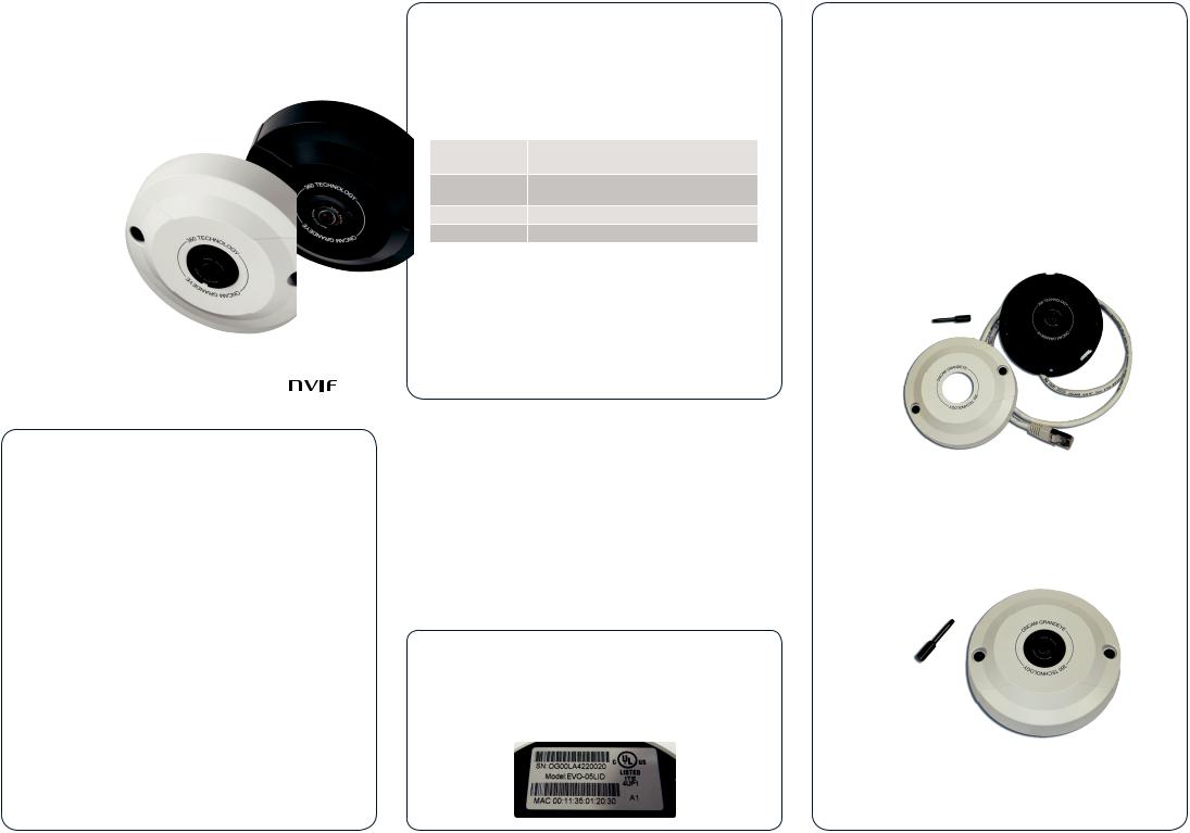
Pelco EVO-05LMD Quick Start Guide

Evolution 05 Mini Indoor
QUICK START GUIDE
EVO-05LJD
EVO-05LID
Welcome
The Oncam Evolution Mini Indoor 360° camera is designed to be connected to an IP network. Configure and operate the camera using a standard internet browser.
Described are the installation and configuration procedures for a standard surface mount camera application.
Power Input |
Power over Ethernet (PoE), |
|
IEEE standard 802.3af |
||
|
||
Operating |
0 to +40°C (-32 to +104°F) |
|
Temperature |
||
|
||
Enclosure |
Polymer |
|
Weight |
0.22 kg (0.48 lbs) |
Supplied Parts
• EVO-05 Mini Camera |
• |
Torx Screwdriver Bit |
|
• |
Mounting Kit |
• |
Drilling Template |
• |
Quick Start Guide |
|
|
Important
•Read these instructions carefully before installing or operating this camera.
•This camera should be installed by a qualified service person and the installation should conform to local and national regulations.
•This product is only suitable for a surface mount installation and should not be modified or adapted for any type of plenum installation.
•Certified as FCC Class A. In a domestic environment this camera may cause radio interference in which case the user should take adequate measures.
DANGER: RISK OF EXPLOSION IF
REPLACING A BATTERY WITH AN
INCORRECT BATTERY TYPE.
Technical Support
For the A&E, Specification, Installation and User Manual, Software and Firmware visit:
www.pelco.com
Tel: +1 559-292-1981 (International)
Email: techsupport@pelco.com
MAC Address
Document the camera’s installation location and unique MAC address. Find the MAC address printed on the camera label. This information may be needed during the camera configuration.
Mounting & Installation
The Evolution Mini Indoor camera is intended for mounting on flat surfaces, such as walls or ceilings. The camera comes fitted with an RJ45 flying lead for connectivity to data and PoE.
Two Torx screws attach the cover to the base.
1.Prepare the surface by using the supplied drilling template. Drill holes appropriately sized for the two base holes for use with mounting hardware.
NOTICE: Use the hardware appropriate for the surface material that collectively supports at least four times the weight of the camera.
2.Loosen the two cover screws using the Torx tool bit and remove the trim cover.
3.Attach the camera module to a wall or ceiling surface using the two base holes.
4.Route the network cable through the mounting plate cable routing canal to allow concealed cable access from the rear or side of the enclosure.
5.Reattach the trim cover to the camera base and apply power.
6.Remove the screen protection.
 Loading...