


 Loading...
Sarix® IMP Series
Indoor Mini Domes
User Manual
C3955M-B-EN (5/15)
2
Contents |
|
Important Notices ......................................................................................................................................................................... |
5 |
Regulatory Notices .............................................................................................................................................................. |
5 |
Radio and Television Interference ....................................................................................................................................... |
5 |
Legal Notice......................................................................................................................................................................... |
5 |
Video Quality Caution .......................................................................................................................................................... |
6 |
Frame Rate Notice Regarding User Selected Options ........................................................................................................ |
6 |
Open Source Software ........................................................................................................................................................ |
6 |
KCC Certification ................................................................................................................................................................. |
7 |
Korean Class A EMC .................................................................................................................................................. |
7 |
ESD Warning....................................................................................................................................................................... |
7 |
Network Topology Statement ....................................................................................................................................................... |
7 |
Legal Notice (Audio Notice).......................................................................................................................................................... |
7 |
Preface......................................................................................................................................................................................... |
8 |
1. Product Overview.............................................................................................................................................................. |
9 |
1.1 Dimensions.................................................................................................................................................................... |
9 |
1.2 Physical Characteristics............................................................................................................................................... |
10 |
2. Installation and Connection ........................................................................................................................................ |
11 |
2.1 Unpacking Everything.................................................................................................................................................. |
11 |
2.2 Optional Accessories ................................................................................................................................................... |
11 |
2.3 Installation.................................................................................................................................................................... |
11 |
2.3.1 Checking Appearance ...................................................................................................................................... |
11 |
2.3.2 Disassembling the Camera .............................................................................................................................. |
11 |
2.3.3 Connecting the Wires ....................................................................................................................................... |
12 |
2.3.4 Installing the Camera........................................................................................................................................ |
12 |
2.3.5 Positioning the Camera .................................................................................................................................... |
16 |
2.3.6 Adjusting the Focus.......................................................................................................................................... |
16 |
2.3.7 Network Topology ............................................................................................................................................ |
17 |
2.3.8 System Requirements ...................................................................................................................................... |
18 |
2.4 Connection................................................................................................................................................................... |
19 |
3
2.4.1 Default IP Address ........................................................................................................................................... |
19 |
2.4.2 Connecting from a Computer & Viewing Preparation ....................................................................................... |
19 |
3. Administration and Configuration.............................................................................................................................. |
20 |
3.1 Live .............................................................................................................................................................................. |
20 |
3.1.1 Zoom and Focus Controls ................................................................................................................................ |
21 |
3.2 Settings........................................................................................................................................................................ |
21 |
3.2.1 System ............................................................................................................................................................. |
22 |
3.2.2 Network ............................................................................................................................................................ |
25 |
3.2.3 Imaging............................................................................................................................................................. |
36 |
3.2.4 A/V Streams ..................................................................................................................................................... |
41 |
3.2.5 Users................................................................................................................................................................ |
46 |
3.2.6 Events .............................................................................................................................................................. |
50 |
Technical Specifications............................................................................................................................................................. |
60 |
Pelco Troubleshooting Contact Information ............................................................................................................................... |
64 |
4
Important Notices
REGULATORY NOTICES
This device complies with Part 15 of the FCC Rules. Operation is subject to the following two conditions: (1) this device may not cause harmful interference, and (2) this device must accept any interference received, including interference that may cause undesired operation.
RADIO AND TELEVISION INTERFERENCE
This equipment has been tested and found to comply with the limits of a Class A digital device, pursuant to Part 15 of the FCC rules. These limits are designed to provide reasonable protection against harmful interference when the equipment is operated in a commercial environment. This equipment generates, uses, and can radiate radio frequency energy and, if not installed and used in accordance with the instruction manual, may cause harmful interference to radio communications. Operation of this equipment in a residential area is likely to cause harmful interference in which case the user will be required to correct the interference at his own expense.
Changes and Modifications not expressly approved by the manufacturer or registrant of this equipment can void your authority to operate this equipment under Federal Communications Commission’s rules.
In order to maintain compliance with FCC regulations shielded cables must be used with this equipment. Operation with non-approved equipment or unshielded cables is likely to result in interference to radio and television reception.
This Class A digital apparatus complies with Canadian ICES-003.
Cet appareil numérique de la classe A est conforme à la norme NMB-003 du Canada.
LEGAL NOTICE
SOME PELCO EQUIPMENT CONTAINS, AND THE SOFTWARE ENABLES, AUDIO/VISUAL AND RECORDING CAPABILITIES, THE IMPROPER USE OF WHICH MAY SUBJECT YOU TO CIVIL AND CRIMINAL PENALTIES. APPLICABLE LAWS REGARDING THE USE OF SUCH CAPABILITIES VARY BETWEEN JURISDICTIONS AND MAY REQUIRE, AMONG OTHER THINGS, EXPRESS WRITTEN CONSENT FROM RECORDED SUBJECTS. YOU ARE SOLELY RESPONSIBLE FOR INSURING STRICT COMPLIANCE WITH SUCH LAWS AND FOR STRICT ADHERENCE TO ANY/ALL RIGHTS OF PRIVACY AND PERSONALTY. USE OF THIS EQUIPMENT AND/OR SOFTWARE FOR ILLEGAL SURVEILLANCE OR MONITORING SHALL BE DEEMED UNAUTHORIZED USE IN VIOLATION OF THE END USER SOFTWARE AGREEMENT AND RESULT IN THE IMMEDIATE TERMINATION OF YOUR LICENSE RIGHTS THEREUNDER.
5
VIDEO QUALITY CAUTION
FRAME RATE NOTICE REGARDING USER SELECTED OPTIONS
Pelco systems are capable of providing high quality video for both live viewing and playback. However, the systems can be used in lower quality modes, which can degrade picture quality, to allow for a slower rate of data transfer and to reduce the amount of video data stored. The picture quality can be degraded by either lowering the resolution, reducing the picture rate, or both. A picture degraded by having a reduced resolution may result in an image that is less clear or even indiscernible. A picture degraded by reducing the picture rate has fewer frames per second, which can result in images that appear to jump or move more quickly than normal during playback. Lower frame rates may result in a key event not being recorded by the system.
Judgment as to the suitability of the products for users' purposes is solely the users' responsibility. Users shall determine the suitability of the products for their own intended application, picture rate and picture quality. In the event users intend to use the video for evidentiary purposes in a judicial proceeding or otherwise, users should consult with their attorney regarding any particular requirements for such use.
OPEN SOURCE SOFTWARE
This product includes certain open source or other software originated from third parties that is subject to the GNU General Public License (GPL), GNU Library/Lesser General Public License (LGPL) and different and/or additional copyright licenses, disclaimers, and notices.
The exact terms of GPL, LGPL, and some other licenses are provided to you with this product. Please refer to the exact terms of the GPL and LGPL at http://www.fsf.org (Free Software Foundation) or http://www.opensource.org (Open Source Initiative) regarding your rights under said license. You may obtain a complete corresponding machine-readable copy of the source code of such software under the GPL or LGPL by sending your request to digitalsupport@pelco.com; the subject line should read Source Code Request. You will then receive an email with a link for you to download the source code.
This offer is valid for a period of three (3) years from the date of the distribution of this product by Pelco.
6

KCC CERTIFICATION
Korean Class A EMC
ESD WARNING
WARNING: This product is sensitive to Electrostatic Discharge (ESD). To avoid ESD damage to this product, use ESD safe practices during installation. Before touching, adjusting or handling this product, correctly attach an ESD wrist strap to your wrist and appropriately discharge your body and tools. For more information about ESD control and safe handling practices of electronics, please refer to ANSI/ESD S20.20-1999 or contact the Electrostatic Discharge Association (www.esda.org).
Network Topology Statement
IMPORTANT NOTE. PLEASE READ. The network implementation is shown as a general representation only and is not intended to show a detailed network topology. Your actual network will differ, requiring changes or perhaps additional network equipment to accommodate the system as illustrated. Please contact your local Pelco Representative to discuss your specific requirements.
Legal Notice (Audio Notice)
NOTE: Improper use of audio/visual recording equipment may subject you to civil and criminal penalties. Applicable laws regarding the use of such capabilities vary between jurisdictions and may require, among other things, express written consent from the recorded subjects. You are solely responsible for insuring strict compliance with such laws and for strict adherence to any/all right of privacy and personality.
WARRANTY STATEMENT
For information about Pelco's product warranty and thereto related information, refer to www.pelco.com/warranty.
7
Preface
This user manual is to be used as a reference for the installation and manipulation of the camera including features, functions, and a detailed explanation of the menu tree.
This manual provides the reader with the following information:
Product Overview: the main functions and system requirements of the unit.
Installation and Connection: instructions on unit installation and wire connections.
Administration and Configuration: the main menu navigation and controls explanations.
8
1. Product Overview
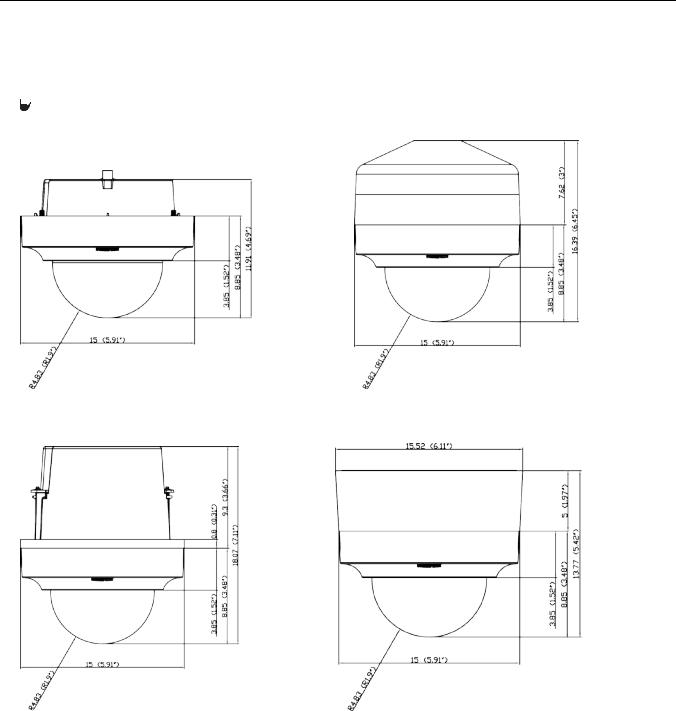
1.1 Dimensions
The Sarix Series IMP Indoor Mini Dome camera has three installation methods (refer to 2.3.4 Installing the Camera on page 12). Figure 1-1 depicts the dimensions of the environmental mini dome as well as the dimensions of three back box configurations (pendant mount, ceiling mount, surface mount).
 VALUES IN PARENTHESES ARE INCHES; ALL OTHERS ARE CENTIMETERS.
INDOOR DOME |
INDOOR DOME IN INDOOR PENDANT MOUNT |
INDOOR DOME IN INDOOR CEILING MOUNT |
INDOOR DOME IN INDOOR SURFACE MOUNT |
FIGURE 1-1: PHYSICAL DIMENSIONS
9

1.2 Physical Characteristics
|
|
FIGURE 1-2: CAMERA CONNECTIONS AND FEATURES 1/2


|
|
|
|
|
|
FIGURE 1-3: CAMERA CONNECTIONS AND FEATURES 2/2
1.Network Cable: Connect the network cable, pass the cable through the cable hole and fix it to the cable slot as the figure shows.
2.24 VAC Power: Supports 24 VAC as the power source.
3.Digital I/O Connectors
A.Alarm Out: Using the “OUT” and “COM” ports, connect to an external device to be triggered through alarm output signals.
B.Alarm In: Using the “IN” and “ ” (ground) ports, connect to an external device that can trigger alarm input signals.
C.Audio In: Using the “+” and “-“ ports, connect to an external device like a microphone that receives sound for the camera.
4.RJ-45 Network Port: Connects the camera to the IP network. Also supplies power to the camera through the network using PoE. If PoE is not available, the camera is prewired for 24 VAC.
5.Dome Liner
6.Lens
7.Default: Using a small tool, such as a paper clip, hold down the reset button longer than 5 seconds to reset the camera to factory defaults.
8.Micro-SD Card: To record images when events happen.
9.Reset: Using a small tool, such as a paper clip, press the reset button briefly and release to restart the camera.
10
2. Installation and Connection
2.1 Unpacking Everything
Check all items in the product box against the order form and the packing slip. In addition to this manual, the items below are included in the product box:
One indoor mini dome camera
One resource CD
One printed quick installation guide
One terminal header 2P
One terminal header 8P
One wrench pin Torx
Please contact your dealer if any items are missing.
2.2 Optional Accessories
IMPBB-S: Sarix Indoor Surface Mount for Mini Dome White
IMPBB-P: Sarix Indoor Pendant Mount for Mini Dome White
IMPBB-I: Sarix Indoor In-Ceiling Mount for Mini Dome
2.3 Installation
Following tools might help you complete the installation:
a drill
screwdrivers
wire cutters
2.3.1 Checking Appearance
Although the protective materials used for the packaging should be able to protect the unit from most accidents during transportation, check the unit and its accessories for any visible damage.
Remove the protective film to check items in accordance with the list in 2.1 Unpacking Everything.
2.3.2 Disassembling the Camera
Before you mount and adjust the camera, push and remove the dome cover (#2) with caution.
|
Camera Body
Dome Cover
FIGURE 2-1: DISASSEMBLING THE CAMERA
11
2.3.3 Connecting the Wires
This unit supports one of the following options as power supply.
•24 VAC: Connect 24V (~) cables to terminals ~24 VAC
•PoE: Connect the RJ-45 network connector to a PoE compatible network device that has supplied power through the Ethernet cable.
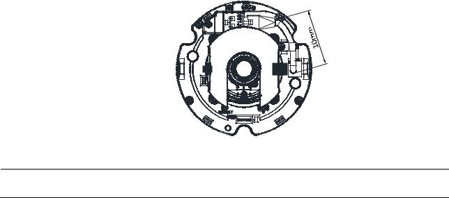
•(Optional) Insert audio cable and alarm cable to the unit, and connect the network cable to the RJ-45 network port of a switch. Refer to Network Cable in 1.2 Physical Characteristics to manage the cables.
NOTE: To avoid the length deficiency, you should reserve about 10mm length of the network cable for connecting the cable to the RJ-45 network port before attaching the cable to the cable slot.
FIGURE 2-2: CONNECTING THE NETWORK CABLE
Caution To avoid damage to the unit, never connect more than one type of power supply (PoE IEEE802.3 Ethernet Class 2 or AC 24V power plug) at the same time.
2.3.4 Installing the Camera
You can install the Sarix Series dome camera using one of the following installation methods:
Surface Mount (refer to 2.3.4.1 Surface Installation).
Pendant Mount (refer to 2.3.4.2 Pendant Installation).
In-Ceiling Mount (refer to 2.3.4.3 In-Ceiling Installation).
2.3.4.1 Surface Installation
Surface Installation involves mounting the camera to the wall with the IMPBB-S, Sarix Indoor Surface Mount for Mini
Dome White.
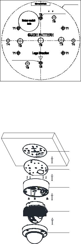
1.Pass all cables through the back box cable hole and attach the camera body (#2) to the back box (#1).
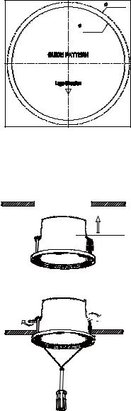
2.Attach the guide pattern (supplied with mount) that is used for surface mount to the wall or ceiling.
12
Out er  6 (
6 (  0. 25i nch) Hol es ( FOR PLASTI C ANCHOR )
 145mm( 5. 7")
I nner |
3. 3( 0. 125i nch) |
Hol es |
( M4 or |
#6 TYPE SCREW ) |
|
T1: Doubl e |
gang |
T2: Si ngl e |
gang |
T3: Pel co |
I M- VE Mount |
T4: 4” Square b ox |
|
T5: Pel co |
I M Mount |
FIGURE 2-3: ATTACHING THE GUIDE PATTERN
3.According to the guide pattern (#1), drill a bottom conduit hole or side conduit hole and pull the wires through the hole.
4.Attach the mount plate (#2) of surface mount back plate to the mounting surface with proper screws.
5.Secure the back box (#3) to the mounting surface with three captive screws.
6.Position the camera as needed (refer to 2.3.5 Positioning the Camera).
7.Focus the lens (refer to 2.3.6 Adjusting the Focus).
8.Install the dome cover (#5) and complete the installation.
Guide Pattern
Mount Plate
Back Box
Camera Body
Dome Cover
FIGURE 2-4: SURFACE INSTALLATION
13
2.3.4.2 Pendant Installation
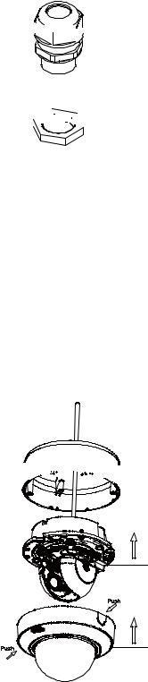
The Pendant Installation involves mounting the camera to the wall with the IMPBB-P, Sarix Indoor Pendant Mount for Mini Dome White. To attach the camera into the back box, it must be installed with a 3/4” rain-tight compression gland and a lock nut (both are not supplied) as shown in Figure 2-5.


Rain-tight Compression
glandLock Nut


FIGURE 2-5: RAIN-TIGHT& LOCK NUT
Refer to Figure 2-6 for pendant installation.
1.Pass all cables through the pendant pipe cable hole. (Use mounting screws appropriate to your installation.)
2.Screw the rain-tight compression gland onto the pipe until tight. Slide the back box (#1) onto the pipe until it rests on the underside of the rain-tight compression gland.
3.Screw the lock nut onto the pipe protruding from beneath the back box. Tighten until the back box is held firmly in place.
4.Mount the camera body (#2) to the back box (#1).
5.Use screws to attach the back box to the mounting surface.
6.Position the camera as needed (refer to 2.3.5 Positioning the Camera).
7.Focus the lens (refer to 2.3.6 Adjusting the Focus).
8.Install the dome cover (#3) and complete the installation.


|
Back Box
Camera Body
Dome Cover
FIGURE 2-6: PENDANT INSTALLATION
14
2.3.4.3 In-Ceiling Installation
The In-Ceiling Installation involves mounting the camera into the ceiling with the IMPBB-I, Sarix Indoor In-Ceiling Mount for Mini Dome.
1.Attach the guide pattern (supplied with mount) used for in-ceiling mount to the wall or ceiling.
145mm ( 5. 7" ) |
134 mm ( 5. 3" ) |
( Backbox) |
FIGURE 2-7: ATTACHING THE GUIDE PATTERN |
2.According the guide pattern, cut a hole in the ceiling/wall.
3.Insert the back box (#1) into the hole and screw the two screws with a screwdriver so the antidropping claspers (#4) can slide out to secure the back box into the ceiling (refer to Figure 2-8 & Figure 2-9).
FIGURE 2-8: INSERTING THE BACK BOX


FIGURE 2-9: SECURING THE BACK BOX
4.Pass all cables through the back box cable hole and attach the camera body (#2) to the back box (#1).
5.Position the camera as needed (refer to 2.3.5 Positioning the Camera).
6.Focus the lens (refer to 2.3.6 Adjusting the Focus).
7.Install the dome cover (#3) and complete the installation.
15
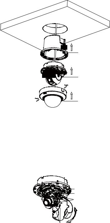
|
Back Box
Camera Body
Dome Cover
FIGURE 2-10: IN-CEILING INSTALLATION
2.3.5 Positioning the Camera
1.Retract the dome liner.
2.View the camera image using the browser (refer to 2.4 Connection).
3.Use a small Phillips screwdriver to loosen the screw (#5) for tilt adjustment.
4.Manually rotate and tilt the camera module to position the camera. Do not over-rotate the module. WARNING: Excessively turning the module in one direction could result in damage to the wiring.
|
|
|


FIGURE 2-12: POSITIONING THE CAMERA
Pan = 355°
Rotate = 360°
Tilt = 90°
Dome liner =90°
2.3.6 Adjusting the Focus
1.View the camera image using the browser (refer to 2.4 Connection).
2.Use the settings in the Web interface (refer to 3.2.3.3 Focus) to adjust the zoom and focus of the lens to the desired field of view.
3.Also the focus can be adjusted by moving the zoom slider and using the Focus options in the live webpage. NOTE: Focus adjustment is done exclusively with Web UI.
16
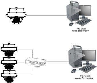
2.3.7 Network Topology
The camera can deliver video images and audio in real time using the Internet and Intranet. It's equipped with Ethernet RJ-45 network interface.
FIGURE 2-13: NETWORK TOPOLOGY TYPE
FIGURE 2-14: NETWORK TOPOLOGY TYPE
17

2.3.8 System Requirements
The table below lists the minimum requirements to implement and operate a unit. Network and processor bandwidth limitations might cause the video stream to pause or appear pixilated when additional Web-interface users connect to the camera. Decrease the images per second (ips), resolution, compression, or bit rate settings of the Web interface video streams to compensate for network/processor limitations.
|
|
|
|
TABLE 2-1: SYSTEM REQUIREMENTS |
|
|
|
|
|
||
|
System Hardware |
|
|
||
|
CPU |
|
|
Intel® Pentium® 4 microprocessor, 2.4GHz or equivalent |
|
|
RAM |
|
|
1 GB or above |
|
|
Monitor |
|
|
Minimum of 1024 x 768 resolution, 16or 32-bit pixel color resolution |
|
|
System Software |
|
|
||
|
Operating System |
Microsoft® Windows® XP, Vista 32 and 64 bit, Win7 32 and 64 bit |
|||
|
Browser |
|
|
Internet Explorer® 9.0 and later, Apple® Safari® 7.0.6, Mozilla® Firefox® 31.0, Google® |
|
|
|
|
|
Chrome™ 37.0.2062.124 m |
|
|
Media Player |
|
Pelco Media Player or QuickTime® 7.6.5 for Windows XP, Windows Vista, and Windows 7; or |
||
|
|
|
|
QuickTime 7.6.4 for Mac OS X 10.4 (or later) |
|
|
Unit |
|
|
|
|
|
Power Supply |
|
AC 24V / PoE |
||
|
|
|
|
||
Note |
1. |
All the installation and operations should comply with your local electricity safety rules. |
|||
|
|
2. |
Pelco Media Player is recommended for control, smoothness, and reduced latency as compared to |
||
|
|
|
QuickTime. The PMP is downloadable from Pelco web site: www.pelco.com/mediaplayer. |
||
|
|
3. |
This product is not compatible with QuickTime version 7.6.4 for Windows XP or Windows Vista. If |
||
|
|
|
you have this version installed on your PC, you will need to upgrade to QuickTime version 7.6.5. |
||
|
|
4. |
Network and processor bandwidth limitations might cause the video stream to pause or appear |
||
|
|
|
pixelated when additional Web-interface users connect to the camera. Decrease the images per |
||
second (ips), resolution, compression, or bit rate settings of the Web interface video streams to compensate for network or processor limitations.
18

2.4 Connection
2.4.1 Default IP Address
The unit’s default IP address is 192.168.0.20 and sub mask is 255.255.255.0. When setting default IP address of 192.168.0.20 the camera will check to see if that address is already in use and will bump the last octet of the address by 1 if it is. The bump last octet of IP Address by 1 will continue until an unused IP address is found.
However, if you have a DHCP server in your network, the unit would obtain an IP address automatically from the DHCP server so that you don’t need to change the camera’s IP address. The factory default is DHCP On and 192.168.0.20 assignment only occurs when camera is set for DHCP but a DHCP server does not respond to request for an IP address.
2.4.2 Connecting from a Computer & Viewing Preparation
2.4.2.1 Using Pelco Device Utility Software to Get Camera’s IP Address
Pelco Device Utility software is a utility program that helps users to manage and configure the camera. Use the utility to find the IP address since the default option is to obtain an IP address via DHCP and therefore the IP address will NOT be known. Steps to get the utility program running are listed below.
1.Finish installing the Device Utility to the computer according to the installation instructions.
2.Log in to the Device Utility by entering the camera’s User name and Password. In the window, enter the default user name: admin and password: admin, then click Enter DU2 button to log in.
3.In the Manage Devices page, you can click Refresh Device List or Add New Device to search for the devices.
4.From the Device List, you can get series information about camera, IP Address included.
For more information about using the Device Utility, click this green icon " " on the upper-right corner of the Device Utility page.
2.4.2.2 Connecting from a Computer
1.Check the networking available between the unit and the computer. Ping the default IP address. Start a command prompt (Windows: from the Start Menu,select Program. Select Accessories and choose Command Prompt.), and type “Ping 192.168.0.20”. If the message “Reply from…” appears, it means the connection is available.
2.Start Internet Explorer and enter IP address: 192.168.0.20. A login window should pop up. In the window, enter the
default user name: admin and password: admin to log in.
NOTE: If you do not know the camera’s IP address, you can locate it using the Pelco Device Utility software (refer to 2.4.2.1 Using Pelco Device Utility Software to Get Camera’s IP Address).
Further administration on the unit can be found in “3. Administration and Configuration".
FIGURE 2-15: LOGIN WINDOW
19

3. Administration and Configuration
3.1 Live
Simply click on Live on the top right side of the browser window while accessing the IP address of the unit, and a live video is displayed directly in the browser window. When clicked on Settings, a window will pop up for configuring “System”, “Network”, “Imaging”, “A/V Streams”, “Users”, and “Events”. Please refer to 3.2 Settings on page 21 for more information. The current logged in identity shows to the right of the Help. Click on Logout admin of the administration window and configuration will return to the camera image screen.
* Figures of 3. Administration and Configuration are taken from the 3MP model for web interface introduction purposes. Options within each item may differ slightly among series products and the differences will be marked in a NOTE.
The following are explanations to the tabs on the Live window.
Select Stream: Selects the viewable video stream that is displayed in live view (primary or secondary) and selects unicast or multicast settings.
Maximize Viewing Area: Scales the image to the full size of the browser. To resize the video pane to normal view, click the Show Toolbar button in the upper-right corner of the window.
Open Stream in New Window: Opens the video in a scalable, independent window. Opening the video in a separate window allows you to view the video while other applications are running. This window can be minimized, maximized, or closed using the title bar buttons of the active window. The window can also be resized to your specifications by dragging the lower-right corner of the window.
FIGURE 3-1: LIVE VIEW
20
Loading...