


 Loading...
I N S T A L L A T I O N / O P E R A T I O N
IM Series
Network Dome Camera
Sarix™ Technology
C2973M-B (1/10)

Contents
Important Notices . . . . . . . . . . . . . . . . . . . . . . . . . . . . . . . . . . . . . . . . . . . . . . . . . . . . . . . . . . . . . . . . . . . . . . . . . . . . . . . . . . . . . . . . . . . . . . . . . . . . . 6
Legal Notice . . . . . . . . . . . . . . . . . . . . . . . . . . . . . . . . . . . . . . . . . . . . . . . . . . . . . . . . . . . . . . . . . . . . . . . . . . . . . . . . . . . . . . . . . . . . . . . . . . . . . 6
Regulatory Notices . . . . . . . . . . . . . . . . . . . . . . . . . . . . . . . . . . . . . . . . . . . . . . . . . . . . . . . . . . . . . . . . . . . . . . . . . . . . . . . . . . . . . . . . . . . . . . . . 6
Video Quality Caution . . . . . . . . . . . . . . . . . . . . . . . . . . . . . . . . . . . . . . . . . . . . . . . . . . . . . . . . . . . . . . . . . . . . . . . . . . . . . . . . . . . . . . . . . . . . . . 6
Frame Rate Notice Regarding User-Selected Options . . . . . . . . . . . . . . . . . . . . . . . . . . . . . . . . . . . . . . . . . . . . . . . . . . . . . . . . . . . . . . . . 6
Open Source Software Notice . . . . . . . . . . . . . . . . . . . . . . . . . . . . . . . . . . . . . . . . . . . . . . . . . . . . . . . . . . . . . . . . . . . . . . . . . . . . . . . . . . . . . . . 6
Introduction . . . . . . . . . . . . . . . . . . . . . . . . . . . . . . . . . . . . . . . . . . . . . . . . . . . . . . . . . . . . . . . . . . . . . . . . . . . . . . . . . . . . . . . . . . . . . . . . . . . . . . . . . . 7
Compatible Systems . . . . . . . . . . . . . . . . . . . . . . . . . . . . . . . . . . . . . . . . . . . . . . . . . . . . . . . . . . . . . . . . . . . . . . . . . . . . . . . . . . . . . . . . . . . . . . . 7
Models . . . . . . . . . . . . . . . . . . . . . . . . . . . . . . . . . . . . . . . . . . . . . . . . . . . . . . . . . . . . . . . . . . . . . . . . . . . . . . . . . . . . . . . . . . . . . . . . . . . . . . . . . 7
Getting Started . . . . . . . . . . . . . . . . . . . . . . . . . . . . . . . . . . . . . . . . . . . . . . . . . . . . . . . . . . . . . . . . . . . . . . . . . . . . . . . . . . . . . . . . . . . . . . . . . . . . . . . 8
Parts List . . . . . . . . . . . . . . . . . . . . . . . . . . . . . . . . . . . . . . . . . . . . . . . . . . . . . . . . . . . . . . . . . . . . . . . . . . . . . . . . . . . . . . . . . . . . . . . . . . . . . . . . 8
Product Overview. . . . . . . . . . . . . . . . . . . . . . . . . . . . . . . . . . . . . . . . . . . . . . . . . . . . . . . . . . . . . . . . . . . . . . . . . . . . . . . . . . . . . . . . . . . . . . . . . . . . . . 9
Product Label . . . . . . . . . . . . . . . . . . . . . . . . . . . . . . . . . . . . . . . . . . . . . . . . . . . . . . . . . . . . . . . . . . . . . . . . . . . . . . . . . . . . . . . . . . . . . . . . . . . . 9
Installation . . . . . . . . . . . . . . . . . . . . . . . . . . . . . . . . . . . . . . . . . . . . . . . . . . . . . . . . . . . . . . . . . . . . . . . . . . . . . . . . . . . . . . . . . . . . . . . . . . . . . . . . . . 10 Orienting the Camera . . . . . . . . . . . . . . . . . . . . . . . . . . . . . . . . . . . . . . . . . . . . . . . . . . . . . . . . . . . . . . . . . . . . . . . . . . . . . . . . . . . . . . . . . . . . . 10 In-Ceiling Installation . . . . . . . . . . . . . . . . . . . . . . . . . . . . . . . . . . . . . . . . . . . . . . . . . . . . . . . . . . . . . . . . . . . . . . . . . . . . . . . . . . . . . . . . . . . . . 11 Fixed Ceiling or Wall . . . . . . . . . . . . . . . . . . . . . . . . . . . . . . . . . . . . . . . . . . . . . . . . . . . . . . . . . . . . . . . . . . . . . . . . . . . . . . . . . . . . . . . . . 11 Suspended Ceiling . . . . . . . . . . . . . . . . . . . . . . . . . . . . . . . . . . . . . . . . . . . . . . . . . . . . . . . . . . . . . . . . . . . . . . . . . . . . . . . . . . . . . . . . . . . 12 4S Deep Electrical box. . . . . . . . . . . . . . . . . . . . . . . . . . . . . . . . . . . . . . . . . . . . . . . . . . . . . . . . . . . . . . . . . . . . . . . . . . . . . . . . . . . . . . . . 13
Surface Installation. . . . . . . . . . . . . . . . . . . . . . . . . . . . . . . . . . . . . . . . . . . . . . . . . . . . . . . . . . . . . . . . . . . . . . . . . . . . . . . . . . . . . . . . . . . . . . . 14 Ceiling or Wall . . . . . . . . . . . . . . . . . . . . . . . . . . . . . . . . . . . . . . . . . . . . . . . . . . . . . . . . . . . . . . . . . . . . . . . . . . . . . . . . . . . . . . . . . . . . . . 14 4S Standard Electrical Box . . . . . . . . . . . . . . . . . . . . . . . . . . . . . . . . . . . . . . . . . . . . . . . . . . . . . . . . . . . . . . . . . . . . . . . . . . . . . . . . . . . . 16
Positioning the Camera. . . . . . . . . . . . . . . . . . . . . . . . . . . . . . . . . . . . . . . . . . . . . . . . . . . . . . . . . . . . . . . . . . . . . . . . . . . . . . . . . . . . . . . . . . . . 17 Adjusting the Focus . . . . . . . . . . . . . . . . . . . . . . . . . . . . . . . . . . . . . . . . . . . . . . . . . . . . . . . . . . . . . . . . . . . . . . . . . . . . . . . . . . . . . . . . . . . . . . 18 Focusing IMS0 Series Models. . . . . . . . . . . . . . . . . . . . . . . . . . . . . . . . . . . . . . . . . . . . . . . . . . . . . . . . . . . . . . . . . . . . . . . . . . . . . . . . . . 18 Focusing IM10 Series Models . . . . . . . . . . . . . . . . . . . . . . . . . . . . . . . . . . . . . . . . . . . . . . . . . . . . . . . . . . . . . . . . . . . . . . . . . . . . . . . . . . 18 Installing the Dome Liner and Lower Dome . . . . . . . . . . . . . . . . . . . . . . . . . . . . . . . . . . . . . . . . . . . . . . . . . . . . . . . . . . . . . . . . . . . . . . . . . . . . 19 Service Cable . . . . . . . . . . . . . . . . . . . . . . . . . . . . . . . . . . . . . . . . . . . . . . . . . . . . . . . . . . . . . . . . . . . . . . . . . . . . . . . . . . . . . . . . . . . . . . . . . . . 20 Wiring . . . . . . . . . . . . . . . . . . . . . . . . . . . . . . . . . . . . . . . . . . . . . . . . . . . . . . . . . . . . . . . . . . . . . . . . . . . . . . . . . . . . . . . . . . . . . . . . . . . . . . . . . 21 Cat5 Cable . . . . . . . . . . . . . . . . . . . . . . . . . . . . . . . . . . . . . . . . . . . . . . . . . . . . . . . . . . . . . . . . . . . . . . . . . . . . . . . . . . . . . . . . . . . . . . . . . 21 Audio Wiring . . . . . . . . . . . . . . . . . . . . . . . . . . . . . . . . . . . . . . . . . . . . . . . . . . . . . . . . . . . . . . . . . . . . . . . . . . . . . . . . . . . . . . . . . . . . . . . 22
Operation . . . . . . . . . . . . . . . . . . . . . . . . . . . . . . . . . . . . . . . . . . . . . . . . . . . . . . . . . . . . . . . . . . . . . . . . . . . . . . . . . . . . . . . . . . . . . . . . . . . . . . . . . . . 23
Camera Configuration Sequence . . . . . . . . . . . . . . . . . . . . . . . . . . . . . . . . . . . . . . . . . . . . . . . . . . . . . . . . . . . . . . . . . . . . . . . . . . . . . . . . . . . . 23
Minimum System Requirements . . . . . . . . . . . . . . . . . . . . . . . . . . . . . . . . . . . . . . . . . . . . . . . . . . . . . . . . . . . . . . . . . . . . . . . . . . . . . . . . . . . . 23
Accessing the IP Camera . . . . . . . . . . . . . . . . . . . . . . . . . . . . . . . . . . . . . . . . . . . . . . . . . . . . . . . . . . . . . . . . . . . . . . . . . . . . . . . . . . . . . . . . . . 24
Logging on to the Camera . . . . . . . . . . . . . . . . . . . . . . . . . . . . . . . . . . . . . . . . . . . . . . . . . . . . . . . . . . . . . . . . . . . . . . . . . . . . . . . . . . . . . 24
Live Video Page . . . . . . . . . . . . . . . . . . . . . . . . . . . . . . . . . . . . . . . . . . . . . . . . . . . . . . . . . . . . . . . . . . . . . . . . . . . . . . . . . . . . . . . . . . . . . . . . . . . . . . 25
Live Video Page Icons . . . . . . . . . . . . . . . . . . . . . . . . . . . . . . . . . . . . . . . . . . . . . . . . . . . . . . . . . . . . . . . . . . . . . . . . . . . . . . . . . . . . . . . . . . . . . 26
Selecting a Stream . . . . . . . . . . . . . . . . . . . . . . . . . . . . . . . . . . . . . . . . . . . . . . . . . . . . . . . . . . . . . . . . . . . . . . . . . . . . . . . . . . . . . . . . . . . . . . . 27
Primary Stream and Secondary Stream. . . . . . . . . . . . . . . . . . . . . . . . . . . . . . . . . . . . . . . . . . . . . . . . . . . . . . . . . . . . . . . . . . . . . . . . . . . 27
QuickView Stream . . . . . . . . . . . . . . . . . . . . . . . . . . . . . . . . . . . . . . . . . . . . . . . . . . . . . . . . . . . . . . . . . . . . . . . . . . . . . . . . . . . . . . . . . . . 27
Unicast . . . . . . . . . . . . . . . . . . . . . . . . . . . . . . . . . . . . . . . . . . . . . . . . . . . . . . . . . . . . . . . . . . . . . . . . . . . . . . . . . . . . . . . . . . . . . . . . . . . . 28
Multicast . . . . . . . . . . . . . . . . . . . . . . . . . . . . . . . . . . . . . . . . . . . . . . . . . . . . . . . . . . . . . . . . . . . . . . . . . . . . . . . . . . . . . . . . . . . . . . . . . . 28
Taking a Snapshot . . . . . . . . . . . . . . . . . . . . . . . . . . . . . . . . . . . . . . . . . . . . . . . . . . . . . . . . . . . . . . . . . . . . . . . . . . . . . . . . . . . . . . . . . . . . . . . 29
Displaying Video in the Multiscreen View . . . . . . . . . . . . . . . . . . . . . . . . . . . . . . . . . . . . . . . . . . . . . . . . . . . . . . . . . . . . . . . . . . . . . . . . . . . . . 29
Settings Page. . . . . . . . . . . . . . . . . . . . . . . . . . . . . . . . . . . . . . . . . . . . . . . . . . . . . . . . . . . . . . . . . . . . . . . . . . . . . . . . . . . . . . . . . . . . . . . . . . . . . . . . 30
Accessing the Camera Menus . . . . . . . . . . . . . . . . . . . . . . . . . . . . . . . . . . . . . . . . . . . . . . . . . . . . . . . . . . . . . . . . . . . . . . . . . . . . . . . . . . . . . . 30
System Tab . . . . . . . . . . . . . . . . . . . . . . . . . . . . . . . . . . . . . . . . . . . . . . . . . . . . . . . . . . . . . . . . . . . . . . . . . . . . . . . . . . . . . . . . . . . . . . . . . . . . . . . . . 31
Changing the Device Name . . . . . . . . . . . . . . . . . . . . . . . . . . . . . . . . . . . . . . . . . . . . . . . . . . . . . . . . . . . . . . . . . . . . . . . . . . . . . . . . . . . . . . . . 32
Configuring the Time Settings . . . . . . . . . . . . . . . . . . . . . . . . . . . . . . . . . . . . . . . . . . . . . . . . . . . . . . . . . . . . . . . . . . . . . . . . . . . . . . . . . . . . . . 32
Generating a System Log . . . . . . . . . . . . . . . . . . . . . . . . . . . . . . . . . . . . . . . . . . . . . . . . . . . . . . . . . . . . . . . . . . . . . . . . . . . . . . . . . . . . . . . . . . 32
Rebooting the Camera . . . . . . . . . . . . . . . . . . . . . . . . . . . . . . . . . . . . . . . . . . . . . . . . . . . . . . . . . . . . . . . . . . . . . . . . . . . . . . . . . . . . . . . . . . . . 32
Restoring All Camera Defaults . . . . . . . . . . . . . . . . . . . . . . . . . . . . . . . . . . . . . . . . . . . . . . . . . . . . . . . . . . . . . . . . . . . . . . . . . . . . . . . . . . . . . . 32
Network Tab . . . . . . . . . . . . . . . . . . . . . . . . . . . . . . . . . . . . . . . . . . . . . . . . . . . . . . . . . . . . . . . . . . . . . . . . . . . . . . . . . . . . . . . . . . . . . . . . . . . . . . . . 33
Changing the Hostname . . . . . . . . . . . . . . . . . . . . . . . . . . . . . . . . . . . . . . . . . . . . . . . . . . . . . . . . . . . . . . . . . . . . . . . . . . . . . . . . . . . . . . . . . . . 33
C2973M-B (1/10) |
3 |
Turning On DHCP . . . . . . . . . . . . . . . . . . . . . . . . . . . . . . . . . . . . . . . . . . . . . . . . . . . . . . . . . . . . . . . . . . . . . . . . . . . . . . . . . . . . . . . . . . . . . . . . 34 Turning Off DHCP . . . . . . . . . . . . . . . . . . . . . . . . . . . . . . . . . . . . . . . . . . . . . . . . . . . . . . . . . . . . . . . . . . . . . . . . . . . . . . . . . . . . . . . . . . . . . . . . 34 Selecting the Secure Sockets Layer Mode. . . . . . . . . . . . . . . . . . . . . . . . . . . . . . . . . . . . . . . . . . . . . . . . . . . . . . . . . . . . . . . . . . . . . . . . . . . . . 35 Generating a Certificate Request . . . . . . . . . . . . . . . . . . . . . . . . . . . . . . . . . . . . . . . . . . . . . . . . . . . . . . . . . . . . . . . . . . . . . . . . . . . . . . . 36 Generating a Self-Signed Certificate . . . . . . . . . . . . . . . . . . . . . . . . . . . . . . . . . . . . . . . . . . . . . . . . . . . . . . . . . . . . . . . . . . . . . . . . . . . . 36 Enabling Secure Shell. . . . . . . . . . . . . . . . . . . . . . . . . . . . . . . . . . . . . . . . . . . . . . . . . . . . . . . . . . . . . . . . . . . . . . . . . . . . . . . . . . . . . . . . . . . . . 37 Configuring the 802.1x Port Security Settings . . . . . . . . . . . . . . . . . . . . . . . . . . . . . . . . . . . . . . . . . . . . . . . . . . . . . . . . . . . . . . . . . . . . . . . . . . 37
Imaging Tab . . . . . . . . . . . . . . . . . . . . . . . . . . . . . . . . . . . . . . . . . . . . . . . . . . . . . . . . . . . . . . . . . . . . . . . . . . . . . . . . . . . . . . . . . . . . . . . . . . . . . . . . . 38 Configuring the Orientation of the Scene. . . . . . . . . . . . . . . . . . . . . . . . . . . . . . . . . . . . . . . . . . . . . . . . . . . . . . . . . . . . . . . . . . . . . . . . . . . . . . 39 Changing the Digital Processing Settings . . . . . . . . . . . . . . . . . . . . . . . . . . . . . . . . . . . . . . . . . . . . . . . . . . . . . . . . . . . . . . . . . . . . . . . . . . . . . 40 Selecting Auto Exposure Settings . . . . . . . . . . . . . . . . . . . . . . . . . . . . . . . . . . . . . . . . . . . . . . . . . . . . . . . . . . . . . . . . . . . . . . . . . . . . . . . . . . . 41 Selecting Manual Exposure Settings . . . . . . . . . . . . . . . . . . . . . . . . . . . . . . . . . . . . . . . . . . . . . . . . . . . . . . . . . . . . . . . . . . . . . . . . . . . . . . . . . 43 Configuring Auto Focus Settings . . . . . . . . . . . . . . . . . . . . . . . . . . . . . . . . . . . . . . . . . . . . . . . . . . . . . . . . . . . . . . . . . . . . . . . . . . . . . . . . . . . . 44 Configuring Manual Focus Settings . . . . . . . . . . . . . . . . . . . . . . . . . . . . . . . . . . . . . . . . . . . . . . . . . . . . . . . . . . . . . . . . . . . . . . . . . . . . . . . . . . 45 Setting Tone Map Options . . . . . . . . . . . . . . . . . . . . . . . . . . . . . . . . . . . . . . . . . . . . . . . . . . . . . . . . . . . . . . . . . . . . . . . . . . . . . . . . . . . . . . . . . 46 Selecting Auto White Balance Settings. . . . . . . . . . . . . . . . . . . . . . . . . . . . . . . . . . . . . . . . . . . . . . . . . . . . . . . . . . . . . . . . . . . . . . . . . . . . . . . 47 Selecting Manual White Balance Settings . . . . . . . . . . . . . . . . . . . . . . . . . . . . . . . . . . . . . . . . . . . . . . . . . . . . . . . . . . . . . . . . . . . . . . . . . . . . 48 Turning On Window Blanking. . . . . . . . . . . . . . . . . . . . . . . . . . . . . . . . . . . . . . . . . . . . . . . . . . . . . . . . . . . . . . . . . . . . . . . . . . . . . . . . . . . . . . . 49 Turing Off Window blanking. . . . . . . . . . . . . . . . . . . . . . . . . . . . . . . . . . . . . . . . . . . . . . . . . . . . . . . . . . . . . . . . . . . . . . . . . . . . . . . . . . . . . . . . 49 Deleting a Window Blanking Area . . . . . . . . . . . . . . . . . . . . . . . . . . . . . . . . . . . . . . . . . . . . . . . . . . . . . . . . . . . . . . . . . . . . . . . . . . . . . . . . . . . 49
A/V Streams Tab . . . . . . . . . . . . . . . . . . . . . . . . . . . . . . . . . . . . . . . . . . . . . . . . . . . . . . . . . . . . . . . . . . . . . . . . . . . . . . . . . . . . . . . . . . . . . . . . . . . . . 50 Selecting a Video Preset Configuration . . . . . . . . . . . . . . . . . . . . . . . . . . . . . . . . . . . . . . . . . . . . . . . . . . . . . . . . . . . . . . . . . . . . . . . . . . . . . . . 51 Configuring a Custom Video Stream Configuration . . . . . . . . . . . . . . . . . . . . . . . . . . . . . . . . . . . . . . . . . . . . . . . . . . . . . . . . . . . . . . . . . . . . . . 52 Compression Standards. . . . . . . . . . . . . . . . . . . . . . . . . . . . . . . . . . . . . . . . . . . . . . . . . . . . . . . . . . . . . . . . . . . . . . . . . . . . . . . . . . . . . . . 52 Available Camera Resolution . . . . . . . . . . . . . . . . . . . . . . . . . . . . . . . . . . . . . . . . . . . . . . . . . . . . . . . . . . . . . . . . . . . . . . . . . . . . . . . . . . 53 Image Rate. . . . . . . . . . . . . . . . . . . . . . . . . . . . . . . . . . . . . . . . . . . . . . . . . . . . . . . . . . . . . . . . . . . . . . . . . . . . . . . . . . . . . . . . . . . . . . . . . 53 Bit Rate . . . . . . . . . . . . . . . . . . . . . . . . . . . . . . . . . . . . . . . . . . . . . . . . . . . . . . . . . . . . . . . . . . . . . . . . . . . . . . . . . . . . . . . . . . . . . . . . . . . 53 I-Frame Interval . . . . . . . . . . . . . . . . . . . . . . . . . . . . . . . . . . . . . . . . . . . . . . . . . . . . . . . . . . . . . . . . . . . . . . . . . . . . . . . . . . . . . . . . . . . . . 53 Quality of Service for Differentiated Services Code Point . . . . . . . . . . . . . . . . . . . . . . . . . . . . . . . . . . . . . . . . . . . . . . . . . . . . . . . . . . . . 54 Endura Signing. . . . . . . . . . . . . . . . . . . . . . . . . . . . . . . . . . . . . . . . . . . . . . . . . . . . . . . . . . . . . . . . . . . . . . . . . . . . . . . . . . . . . . . . . . . . . . 54 Advance Sharpening . . . . . . . . . . . . . . . . . . . . . . . . . . . . . . . . . . . . . . . . . . . . . . . . . . . . . . . . . . . . . . . . . . . . . . . . . . . . . . . . . . . . . . . . . 54
Selecting the Audio Configuration Settings. . . . . . . . . . . . . . . . . . . . . . . . . . . . . . . . . . . . . . . . . . . . . . . . . . . . . . . . . . . . . . . . . . . . . . . . . . . . 55 Users and Groups Tab . . . . . . . . . . . . . . . . . . . . . . . . . . . . . . . . . . . . . . . . . . . . . . . . . . . . . . . . . . . . . . . . . . . . . . . . . . . . . . . . . . . . . . . . . . . . . . . . . 56 Creating a New User . . . . . . . . . . . . . . . . . . . . . . . . . . . . . . . . . . . . . . . . . . . . . . . . . . . . . . . . . . . . . . . . . . . . . . . . . . . . . . . . . . . . . . . . . . . . . 58 Editing a User . . . . . . . . . . . . . . . . . . . . . . . . . . . . . . . . . . . . . . . . . . . . . . . . . . . . . . . . . . . . . . . . . . . . . . . . . . . . . . . . . . . . . . . . . . . . . . . . . . . 58 Deleting A User. . . . . . . . . . . . . . . . . . . . . . . . . . . . . . . . . . . . . . . . . . . . . . . . . . . . . . . . . . . . . . . . . . . . . . . . . . . . . . . . . . . . . . . . . . . . . . . . . . 59 Creating a New Group . . . . . . . . . . . . . . . . . . . . . . . . . . . . . . . . . . . . . . . . . . . . . . . . . . . . . . . . . . . . . . . . . . . . . . . . . . . . . . . . . . . . . . . . . . . . 59 Editing a Group . . . . . . . . . . . . . . . . . . . . . . . . . . . . . . . . . . . . . . . . . . . . . . . . . . . . . . . . . . . . . . . . . . . . . . . . . . . . . . . . . . . . . . . . . . . . . . . . . . 59 Deleting a Group. . . . . . . . . . . . . . . . . . . . . . . . . . . . . . . . . . . . . . . . . . . . . . . . . . . . . . . . . . . . . . . . . . . . . . . . . . . . . . . . . . . . . . . . . . . . . . . . . 59 General Settings for Users and Groups . . . . . . . . . . . . . . . . . . . . . . . . . . . . . . . . . . . . . . . . . . . . . . . . . . . . . . . . . . . . . . . . . . . . . . . . . . . . . . . 60 Setting the Camera to Node . . . . . . . . . . . . . . . . . . . . . . . . . . . . . . . . . . . . . . . . . . . . . . . . . . . . . . . . . . . . . . . . . . . . . . . . . . . . . . . . . . . 60 Setting the Camera to Mixed . . . . . . . . . . . . . . . . . . . . . . . . . . . . . . . . . . . . . . . . . . . . . . . . . . . . . . . . . . . . . . . . . . . . . . . . . . . . . . . . . . 60
Events Tab . . . . . . . . . . . . . . . . . . . . . . . . . . . . . . . . . . . . . . . . . . . . . . . . . . . . . . . . . . . . . . . . . . . . . . . . . . . . . . . . . . . . . . . . . . . . . . . . . . . . . . . . . . 61 Sources . . . . . . . . . . . . . . . . . . . . . . . . . . . . . . . . . . . . . . . . . . . . . . . . . . . . . . . . . . . . . . . . . . . . . . . . . . . . . . . . . . . . . . . . . . . . . . . . . . . . . . . . 62 Creating a System Event Source . . . . . . . . . . . . . . . . . . . . . . . . . . . . . . . . . . . . . . . . . . . . . . . . . . . . . . . . . . . . . . . . . . . . . . . . . . . . . . . . 62 Creating a Timer Event Source . . . . . . . . . . . . . . . . . . . . . . . . . . . . . . . . . . . . . . . . . . . . . . . . . . . . . . . . . . . . . . . . . . . . . . . . . . . . . . . . . 62 Editing an Event Source. . . . . . . . . . . . . . . . . . . . . . . . . . . . . . . . . . . . . . . . . . . . . . . . . . . . . . . . . . . . . . . . . . . . . . . . . . . . . . . . . . . . . . . 63 Deleting an Event Source . . . . . . . . . . . . . . . . . . . . . . . . . . . . . . . . . . . . . . . . . . . . . . . . . . . . . . . . . . . . . . . . . . . . . . . . . . . . . . . . . . . . . 63 Handlers . . . . . . . . . . . . . . . . . . . . . . . . . . . . . . . . . . . . . . . . . . . . . . . . . . . . . . . . . . . . . . . . . . . . . . . . . . . . . . . . . . . . . . . . . . . . . . . . . . . . . . . 64 Creating an Event Handler: Send Email. . . . . . . . . . . . . . . . . . . . . . . . . . . . . . . . . . . . . . . . . . . . . . . . . . . . . . . . . . . . . . . . . . . . . . . . . . . 64 Creating an Event Handler: Upload JPEG to FTP Server . . . . . . . . . . . . . . . . . . . . . . . . . . . . . . . . . . . . . . . . . . . . . . . . . . . . . . . . . . . . . . 65 Editing an Event Handler . . . . . . . . . . . . . . . . . . . . . . . . . . . . . . . . . . . . . . . . . . . . . . . . . . . . . . . . . . . . . . . . . . . . . . . . . . . . . . . . . . . . . . 65 Deleting an Event Handler. . . . . . . . . . . . . . . . . . . . . . . . . . . . . . . . . . . . . . . . . . . . . . . . . . . . . . . . . . . . . . . . . . . . . . . . . . . . . . . . . . . . . 66 Example Handler Filter Setup . . . . . . . . . . . . . . . . . . . . . . . . . . . . . . . . . . . . . . . . . . . . . . . . . . . . . . . . . . . . . . . . . . . . . . . . . . . . . . . . . . 66
Help Menu . . . . . . . . . . . . . . . . . . . . . . . . . . . . . . . . . . . . . . . . . . . . . . . . . . . . . . . . . . . . . . . . . . . . . . . . . . . . . . . . . . . . . . . . . . . . . . . . . . . . . . . . . . 67
Log Off Menu . . . . . . . . . . . . . . . . . . . . . . . . . . . . . . . . . . . . . . . . . . . . . . . . . . . . . . . . . . . . . . . . . . . . . . . . . . . . . . . . . . . . . . . . . . . . . . . . . . . . . . . . 67
Specifications . . . . . . . . . . . . . . . . . . . . . . . . . . . . . . . . . . . . . . . . . . . . . . . . . . . . . . . . . . . . . . . . . . . . . . . . . . . . . . . . . . . . . . . . . . . . . . . . . . . . . . . 68
IMS0 Series . . . . . . . . . . . . . . . . . . . . . . . . . . . . . . . . . . . . . . . . . . . . . . . . . . . . . . . . . . . . . . . . . . . . . . . . . . . . . . . . . . . . . . . . . . . . . . . . . . . . 68
IM10 Series. . . . . . . . . . . . . . . . . . . . . . . . . . . . . . . . . . . . . . . . . . . . . . . . . . . . . . . . . . . . . . . . . . . . . . . . . . . . . . . . . . . . . . . . . . . . . . . . . . . . . 70
4 |
C2973M-B (1/10) |

List of Illustrations
1 Camera Connections and Features. . . . . . . . . . . . . . . . . . . . . . . . . . . . . . . . . . . . . . . . . . . . . . . . . . . . . . . . . . . . . . . . . . . . . . . . . . . . . . . . . . . . 9 2 Orienting the Camera . . . . . . . . . . . . . . . . . . . . . . . . . . . . . . . . . . . . . . . . . . . . . . . . . . . . . . . . . . . . . . . . . . . . . . . . . . . . . . . . . . . . . . . . . . . . . 10 3 Fixed Ceiling or Wall Installation . . . . . . . . . . . . . . . . . . . . . . . . . . . . . . . . . . . . . . . . . . . . . . . . . . . . . . . . . . . . . . . . . . . . . . . . . . . . . . . . . . . . 11 4 Suspended Ceiling Installation, Adapter Ring . . . . . . . . . . . . . . . . . . . . . . . . . . . . . . . . . . . . . . . . . . . . . . . . . . . . . . . . . . . . . . . . . . . . . . . . . . 12 5 Suspended Ceiling Installation, Surface Mount Ring . . . . . . . . . . . . . . . . . . . . . . . . . . . . . . . . . . . . . . . . . . . . . . . . . . . . . . . . . . . . . . . . . . . . 12 6 4S Deep Electrical Box Installation . . . . . . . . . . . . . . . . . . . . . . . . . . . . . . . . . . . . . . . . . . . . . . . . . . . . . . . . . . . . . . . . . . . . . . . . . . . . . . . . . . 13 7 Routing Wiring for Surface Installations . . . . . . . . . . . . . . . . . . . . . . . . . . . . . . . . . . . . . . . . . . . . . . . . . . . . . . . . . . . . . . . . . . . . . . . . . . . . . . 14 8 Ceiling or Wall Installation. . . . . . . . . . . . . . . . . . . . . . . . . . . . . . . . . . . . . . . . . . . . . . . . . . . . . . . . . . . . . . . . . . . . . . . . . . . . . . . . . . . . . . . . . 15 9 Concrete Ceiling or Wall Installation . . . . . . . . . . . . . . . . . . . . . . . . . . . . . . . . . . . . . . . . . . . . . . . . . . . . . . . . . . . . . . . . . . . . . . . . . . . . . . . . . 15 10 4S Standard Electrical Box Installation . . . . . . . . . . . . . . . . . . . . . . . . . . . . . . . . . . . . . . . . . . . . . . . . . . . . . . . . . . . . . . . . . . . . . . . . . . . . . . . 16 11 Adjusting Pan and Tilt. . . . . . . . . . . . . . . . . . . . . . . . . . . . . . . . . . . . . . . . . . . . . . . . . . . . . . . . . . . . . . . . . . . . . . . . . . . . . . . . . . . . . . . . . . . . . 17 12 Installing the Dome Liner . . . . . . . . . . . . . . . . . . . . . . . . . . . . . . . . . . . . . . . . . . . . . . . . . . . . . . . . . . . . . . . . . . . . . . . . . . . . . . . . . . . . . . . . . . 19 13 Installing the Lower Dome . . . . . . . . . . . . . . . . . . . . . . . . . . . . . . . . . . . . . . . . . . . . . . . . . . . . . . . . . . . . . . . . . . . . . . . . . . . . . . . . . . . . . . . . . 19 14 Attaching the 2.5 mm Monaural Headphone Plug . . . . . . . . . . . . . . . . . . . . . . . . . . . . . . . . . . . . . . . . . . . . . . . . . . . . . . . . . . . . . . . . . . . . . . . 20 15 Cat5 Cable Pin Descriptions . . . . . . . . . . . . . . . . . . . . . . . . . . . . . . . . . . . . . . . . . . . . . . . . . . . . . . . . . . . . . . . . . . . . . . . . . . . . . . . . . . . . . . . . 21 16 Line-In Audio Wiring. . . . . . . . . . . . . . . . . . . . . . . . . . . . . . . . . . . . . . . . . . . . . . . . . . . . . . . . . . . . . . . . . . . . . . . . . . . . . . . . . . . . . . . . . . . . . . 22 17 Live Video Page. . . . . . . . . . . . . . . . . . . . . . . . . . . . . . . . . . . . . . . . . . . . . . . . . . . . . . . . . . . . . . . . . . . . . . . . . . . . . . . . . . . . . . . . . . . . . . . . . . 25 18 SSL Configuration Page . . . . . . . . . . . . . . . . . . . . . . . . . . . . . . . . . . . . . . . . . . . . . . . . . . . . . . . . . . . . . . . . . . . . . . . . . . . . . . . . . . . . . . . . . . . 35 19 SSH Settings Page . . . . . . . . . . . . . . . . . . . . . . . . . . . . . . . . . . . . . . . . . . . . . . . . . . . . . . . . . . . . . . . . . . . . . . . . . . . . . . . . . . . . . . . . . . . . . . . 37 20 Orientation Page . . . . . . . . . . . . . . . . . . . . . . . . . . . . . . . . . . . . . . . . . . . . . . . . . . . . . . . . . . . . . . . . . . . . . . . . . . . . . . . . . . . . . . . . . . . . . . . . . 39 21 Digital Processing Page . . . . . . . . . . . . . . . . . . . . . . . . . . . . . . . . . . . . . . . . . . . . . . . . . . . . . . . . . . . . . . . . . . . . . . . . . . . . . . . . . . . . . . . . . . . 40 22 Auto Exposure Page . . . . . . . . . . . . . . . . . . . . . . . . . . . . . . . . . . . . . . . . . . . . . . . . . . . . . . . . . . . . . . . . . . . . . . . . . . . . . . . . . . . . . . . . . . . . . . 41 23 Manual Exposure Page . . . . . . . . . . . . . . . . . . . . . . . . . . . . . . . . . . . . . . . . . . . . . . . . . . . . . . . . . . . . . . . . . . . . . . . . . . . . . . . . . . . . . . . . . . . . 43 24 Auto Focus Page . . . . . . . . . . . . . . . . . . . . . . . . . . . . . . . . . . . . . . . . . . . . . . . . . . . . . . . . . . . . . . . . . . . . . . . . . . . . . . . . . . . . . . . . . . . . . . . . . 44 25 Manual Focus Page. . . . . . . . . . . . . . . . . . . . . . . . . . . . . . . . . . . . . . . . . . . . . . . . . . . . . . . . . . . . . . . . . . . . . . . . . . . . . . . . . . . . . . . . . . . . . . . 45 26 Tone Map Page . . . . . . . . . . . . . . . . . . . . . . . . . . . . . . . . . . . . . . . . . . . . . . . . . . . . . . . . . . . . . . . . . . . . . . . . . . . . . . . . . . . . . . . . . . . . . . . . . . 46 27 Auto White Balance Page. . . . . . . . . . . . . . . . . . . . . . . . . . . . . . . . . . . . . . . . . . . . . . . . . . . . . . . . . . . . . . . . . . . . . . . . . . . . . . . . . . . . . . . . . . 47 28 Manual White Balance Page . . . . . . . . . . . . . . . . . . . . . . . . . . . . . . . . . . . . . . . . . . . . . . . . . . . . . . . . . . . . . . . . . . . . . . . . . . . . . . . . . . . . . . . 48 29 Window Blanking Page. . . . . . . . . . . . . . . . . . . . . . . . . . . . . . . . . . . . . . . . . . . . . . . . . . . . . . . . . . . . . . . . . . . . . . . . . . . . . . . . . . . . . . . . . . . . 49 30 Select Video Preset Configuration Page. . . . . . . . . . . . . . . . . . . . . . . . . . . . . . . . . . . . . . . . . . . . . . . . . . . . . . . . . . . . . . . . . . . . . . . . . . . . . . . 51 31 Custom Video Stream Configuration Page . . . . . . . . . . . . . . . . . . . . . . . . . . . . . . . . . . . . . . . . . . . . . . . . . . . . . . . . . . . . . . . . . . . . . . . . . . . . . 52 32 Audio Configuration Page. . . . . . . . . . . . . . . . . . . . . . . . . . . . . . . . . . . . . . . . . . . . . . . . . . . . . . . . . . . . . . . . . . . . . . . . . . . . . . . . . . . . . . . . . . 55 33 User Page . . . . . . . . . . . . . . . . . . . . . . . . . . . . . . . . . . . . . . . . . . . . . . . . . . . . . . . . . . . . . . . . . . . . . . . . . . . . . . . . . . . . . . . . . . . . . . . . . . . . . . 56 34 Group Page . . . . . . . . . . . . . . . . . . . . . . . . . . . . . . . . . . . . . . . . . . . . . . . . . . . . . . . . . . . . . . . . . . . . . . . . . . . . . . . . . . . . . . . . . . . . . . . . . . . . . 57 35 User and Group Settings Page . . . . . . . . . . . . . . . . . . . . . . . . . . . . . . . . . . . . . . . . . . . . . . . . . . . . . . . . . . . . . . . . . . . . . . . . . . . . . . . . . . . . . . 60 36 New Event Source Page . . . . . . . . . . . . . . . . . . . . . . . . . . . . . . . . . . . . . . . . . . . . . . . . . . . . . . . . . . . . . . . . . . . . . . . . . . . . . . . . . . . . . . . . . . . 62 37 New Event Handler Page . . . . . . . . . . . . . . . . . . . . . . . . . . . . . . . . . . . . . . . . . . . . . . . . . . . . . . . . . . . . . . . . . . . . . . . . . . . . . . . . . . . . . . . . . . 64
C2973M-B (1/10) |
5 |

Important Notices
LEGAL NOTICE
SOME PELCO EQUIPMENT CONTAINS, AND THE SOFTWARE ENABLES, AUDIO/VISUAL AND RECORDING CAPABILITIES, THE IMPROPER USE OF WHICH MAY SUBJECT YOU TO CIVIL AND CRIMINAL PENALTIES. APPLICABLE LAWS REGARDING THE USE OF SUCH CAPABILITIES VARY BETWEEN JURISDICTIONS AND MAY REQUIRE, AMONG OTHER THINGS, EXPRESS WRITTEN CONSENT FROM RECORDED SUBJECTS. YOU ARE SOLELY RESPONSIBLE FOR INSURING STRICT COMPLIANCE WITH SUCH LAWS AND FOR STRICT ADHERENCE TO ANY/ALL RIGHTS OF PRIVACY AND PERSONALTY. USE OF THIS EQUIPMENT AND/OR SOFTWARE FOR ILLEGAL SURVEILLANCE OR MONITORING SHALL BE DEEMED UNAUTHORIZED USE IN VIOLATION OF THE END USER SOFTWARE AGREEMENT AND RESULT IN THE IMMEDIATE TERMINATION OF YOUR LICENSE RIGHTS THEREUNDER.
REGULATORY NOTICES
This device complies with Part 15 of the FCC Rules. Operation is subject to the following two conditions: (1) this device may not cause harmful interference, and (2) this device must accept any interference received, including interference that may cause undesired operation.
RADIO AND TELEVISION INTERFERENCE
This equipment has been tested and found to comply with the limits of a Class B digital device, pursuant to Part 15 of the FCC Rules. These limits are designed to provide reasonable protection against harmful interference in a residential installation. This equipment generates, uses, and can radiate radio frequency energy and, if not installed and used in accordance with the instructions, may cause harmful interference to radio communications. However there is no guarantee that the interference will not occur in a particular installation. If this equipment does cause harmful interference to radio or television reception, which can be determined by turning the equipment off and on, the user is encouraged to try to correct the interference by one or more of the following measures:
•Reorient or relocate the receiving antenna.
•Increase the separation between the equipment and the receiver.
•Connect the equipment into an outlet on a circuit different from that to which the receiver is connected.
•Consult the dealer or an experienced radio/TV technician for help.
You may also find helpful the following booklet, prepared by the FCC: “How to Identify and Resolve Radio-TV Interference Problems.” This booklet is available from the U.S. Government Printing Office, Washington D.C. 20402.
Changes and Modifications not expressly approved by the manufacturer or registrant of this equipment can void your authority to operate this equipment under Federal Communications Commission’s rules.
This Class B digital apparatus complies with Canadian ICES-003.
Cet appareil numérique de la classe B est conforme à la norme NMB-003 du Canada.
VIDEO QUALITY CAUTION
FRAME RATE NOTICE REGARDING USER-SELECTED OPTIONS
Pelco systems are capable of providing high quality video for both live viewing and playback. However, the systems can be used in lower quality modes, which can degrade picture quality, to allow for a slower rate of data transfer and to reduce the amount of video data stored. The picture quality can be degraded by either lowering the resolution, reducing the picture rate, or both. A picture degraded by having a reduced resolution may result in an image that is less clear or even indiscernible. A picture degraded by reducing the picture rate has fewer frames per second, which can result in images that appear to jump or move more quickly than normal during playback. Lower frame rates may result in a key event not being recorded by the system.
Judgment as to the suitability of the products for users’ purposes is solely the users’ responsibility. Users shall determine the suitability of the products for their own intended application, picture rate and picture quality. In the event users intend to use the video for evidentiary purposes in a judicial proceeding or otherwise, users should consult with their attorney regarding any particular requirements for such use.
OPEN SOURCE SOFTWARE NOTICE
This product includes certain open source or other software originated from third parties that is subject to the GNU General Public License (GPL), GNU Library/Lesser General Public License (LGPL) and different and/or additional copyright licenses, disclaimers, and notices.
The exact terms of GPL, LGPL, and some other licenses are provided to you with this product. Please refer to the exact terms of the GPL and LGPL at http://www.fsf.org (Free Software Foundation) or http://www.opensource.org (Open Source Initiative) regarding your rights under said license. You may obtain a complete corresponding machine-readable copy of the source code of such software under the GPL or LGPL by sending your request to digitalsupport@pelco.com; the subject line should read Source Code Request. You will then receive an email with a link for you to download the source code.
This offer is valid for a period of three (3) years from the date of the distribution of this product by Pelco.
6 |
C2973M-B (1/10) |

Introduction
The IM Series is a mini fixed network dome camera with a built-in, Web-based viewer for live streaming to a standard Web browser (Microsoft® Internet Explorer® or Mozilla® Firefox®). The camera features open architecture connectivity for third-party applications and is also
Endura Enabled™ and compatible with Digital Sentry® to record, manage, configure, and view multiple live streams. Some models are also compatible with DX8100 and DVR5100 video recorders.
The network camera supports up to three compression formats and many resolutions. The two standard compression formats include H.264 and MJPEG. MPEG-4 is also available with IMS0 models. The dual streams can be configured for a variety of resolutions, frame rates, and bit rates.
Both 0.5 and 1.3 megapixel (MPx) color camera models are available. The camera uses a 1/3-inch imager and is shipped with a 2.8~10 mm varifocal megapixel lens installed.
The camera also includes built-in Power over Ethernet (PoE), which supplies power to the camera through the network.
This manual explains how to interface with the camera using Internet Explorer® or Firefox.
COMPATIBLE SYSTEMS
The camera can also be used with an Endura® system as an Endura Enabled device, Digital Sentry, or a third-party system with Pelco’s application programing interface (API). For detailed instructions on configuring the camera using one of these systems, refer to the manual shipped with the system.
For a list of compatible API partners, go to xdn.pelco.com and register as a new user by following the on-screen instructions.
MODELS
IMS0C10-1 |
Sarix IM Series, network fixed dome camera, 0.5 megapixel standard definition color, 2.8~10 mm varifocal megapixel |
|
lens, white trim ring, clear bubble |
IM10C10-1 |
Sarix IM Series, network fixed dome camera, 1.3 megapixel standard definition color, 2.8~10 mm varifocal megapixel |
|
lens, white trim ring, clear bubble |
IM10C10-B1 |
Sarix IM Series, network fixed dome camera, 1.3 megapixel standard definition color, 2.8~10 mm varifocal megapixel |
|
lens, black trim ring, clear bubble |
C2973M-B (1/10) |
7 |
Getting Started
Before installing your network camera, thoroughly familiarize yourself with the information in this section of the manual.
NOTES:
•Pelco recommends connecting the camera to a network that uses a Dynamic Host Configuration Protocol (DHCP) server to address devices.
•Do not use a network hub when configuring the network settings for the camera.
•To ensure secure access to the network camera, place the camera behind a firewall when it is connected to a network.
PARTS LIST
Remove all of the contents from the shipping box.
Qty Description
1Back box and camera module
1Surface mount ring
1Lower dome (includes trim ring and bubble)
1Dome liner
1Adapter ring
14-pin audio connector (IM10 Series models only)
2Screws, #8 x 1.5-inch, Phillips pan head, self tapping
2Screws, #8 x 2.5-inch, Phillips pan head, self tapping
2Screws, #10 x 1.5-inch, Phillips pan head, self tapping
2Screws, 8-32 x 1-inch, Phillips flat head
1Quick Start Guide
1Resource disc
3MAC address labels (extra)
Installation tools and the following parts are needed but not supplied:
Qty Description
1 Service cable (IX-SC)
1 Mounting hardware
8 |
C2973M-B (1/10) |

Product Overview
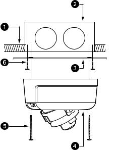
Figure 1. Camera Connections and Features
ìAccessory Port: For use with compatible Pelco accessories.
NOTE: A right-angle mini USB connector must be used to connect Pelco accessories to the accessory port.
îAudio Connector: Supplies line-in audio from a user-supplied microphone. Audio functionality is only available for IM10 Series models, and it can be enabled or disabled using the Web browser.
ïRJ-45 Network Port: Connects the camera to the IP network. Also supplies power to the camera through the network using PoE.
ñMicrophone: Supplies built-in, line-in audio to a PC. Audio functionality is only available for IM10 Series models, and it can be enabled or disabled using the Web browser.
óReset Button (R): Reboots the camera or restores the camera’s factory default settings. This button is recessed. Using a small tool, such as a paper clip, press and release the reset button once to reboot the camera. Press and hold the reset button for 10 seconds to restore the camera to the factory default settings.
NOTE: The lower dome must be removed to access this button.
rNTSC/PAL Button (V): Toggles the service port between NTSC and PAL formats. This button is recessed. Using a small tool, such as a paper clip, press and release the NTSC/PAL button to toggle between NTSC and PAL formats when using the service port. The default setting is NTSC.
NOTE: The lower dome must be removed to access this button.
sService Port: Outputs analog video. Use this port at the installation site to set up the field of view and to focus the camera. When a service cable is connected to the camera, video to the IP stream is disabled.
PRODUCT LABEL
The product label lists the model number, date code, serial number, and Media Access Control (MAC) address. This information might be required for setup. The product label is located on the top of the back box.
C2973M-B (1/10) |
9 |
Installation
You can install the IM Series network dome camera using one of the following installation methods:
•Install in a suspended ceiling or a fixed ceiling/wall (refer to In-Ceiling Installation).
•Mount to the surface of a ceiling/wall (refer to Surface Installation on page 14).
ORIENTING THE CAMERA
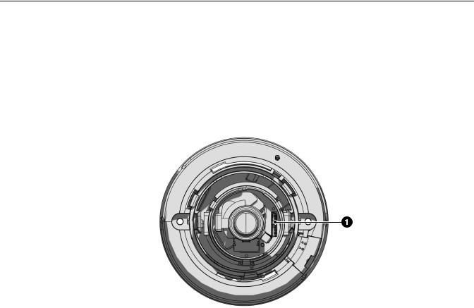
Before attaching the dome camera to the mounting surface, be sure to properly orient the camera to ensure that the video is right-side-up when viewed. The lens connectors should be on the right side of the lens when you are looking directly at the camera (refer to Figure 2).
NOTE: Improper camera orientation can also be corrected using the Web interface (refer to Configuring the Orientation of the Scene on page 39).
Figure 2. Orienting the Camera
ìLens Connectors
10 |
C2973M-B (1/10) |
IN-CEILING INSTALLATION
FIXED CEILING OR WALL
1.Cut a 4-inch (10.16 cm) diameter hole in the ceiling/wall.
2.Pull all wiring through the hole and connect the wiring to the side of the back box:
a.Connect the network cable to the RJ-45 network port on the side of the camera. Refer to Cat5 Cable on page 21 for wiring connections.
b.Connect the necessary wiring for audio (refer to Audio Wiring on page 22).
3.Apply power to the camera.
NOTE: If the camera is not connected to a DHCP server and DHCP is enabled, the configuration sequence might take up to five minutes to complete.
4.Insert the back box into the hole in the ceiling/wall. Be sure to angle the back box during this step to ensure that the wiring is inserted into the hole first and is not bent or damaged.
5.Use 3/16-inch toggle bolts (not supplied) to attach the back box to the mounting surface.
Figure 3. Fixed Ceiling or Wall Installation
ìCeiling/Wall
îBack Box
ï3/16-inch Toggle Bolts (not supplied)
6.Position the camera as needed (refer to Positioning the Camera on page 17).
7.Focus the lens (refer to Adjusting the Focus on page 18).
8.Install the plastic liner and lower dome (refer to Installing the Dome Liner and Lower Dome on page 19).
C2973M-B (1/10) |
11 |
SUSPENDED CEILING
1.Remove the ceiling tile from the ceiling.
2.Cut a 3.75-inch (9.53 cm) diameter hole in the ceiling tile.
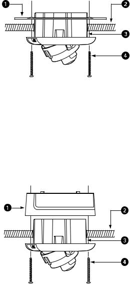
3.Place the adapter ring (supplied) or the surface mount ring on the inside of the ceiling tile.
4.Perform one of the following options:
•Attach the back box to the ceiling tile and adapter ring with two #8 x 1.50-inch Phillips pan head self-tapping screws (supplied; refer to Figure 4).
Figure 4. Suspended Ceiling Installation, Adapter Ring
ìAdapter Ring
îCeiling Tile
ïBack Box
ñ#8 x 1.50-inch Phillips Pan Head Self-Tapping Screws (supplied)
•Attach the back box to the ceiling tile and surface mount ring with two #10 x 1.50-inch Phillips pan head self tapping screws (supplied; refer to Figure 5).
Figure 5. Suspended Ceiling Installation, Surface Mount Ring
ìSurface Mount Ring
îCeiling Tile
ïBack Box
ñ#10 x 1.50-inch Phillips Pan Head Self-Tapping Screws (supplied)
12 |
C2973M-B (1/10) |
5.Replace the ceiling tile.
6.Remove an adjacent ceiling tile and connect the wiring to the side of the back box:
a.Connect the network cable to the RJ-45 network port on the side of the back box. Refer to Cat5 Cable on page 21 for wiring connections.
NOTE: If you are installing the dome using the surface mount ring, do not use network cables with over-molded RJ-45 connectors. These connectors will not fit inside the surface mount ring.
b.Connect the necessary wiring for audio (refer to Audio Wiring on page 22).
7.Apply power to the camera.
NOTE: If the camera is not connected to a DHCP server and DHCP is enabled, the configuration sequence might take up to five minutes to complete.
8.Position the camera as needed (refer to Positioning the Camera on page 17).
9.Focus the lens (refer to Adjusting the Focus on page 18).
10.Install the plastic liner and lower dome (refer to Installing the Dome Liner and Lower Dome on page 19).
4S DEEP ELECTRICAL BOX
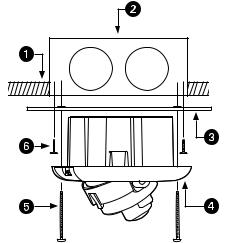
1.Attach the adapter ring (supplied) to a 4S deep electrical box with two 8-32 x 1.00-inch Phillips flat head screws (supplied; refer to Figure 6).
Figure 6. 4S Deep Electrical Box Installation
ìCeiling/Wall
î4S Deep Electrical Box
ïAdapter Ring
ñBack Box
ó#8 x 2.5-inch Phillips Pan Head Self-Tapping Screws (supplied)
r8-32 x 1.00-inch Phillips Flat Head Screws (supplied)
C2973M-B (1/10) |
13 |
2.Connect the wiring to the side of the back box:
a.Connect the network cable to the RJ-45 network port on the side of the back box. Refer to Cat5 Cable on page 21 for wiring connections.
b.Connect the necessary wiring for audio (refer to Audio Wiring on page 22).
3.Apply power to the camera.
NOTE: If the camera is not connected to a DHCP server and DHCP is enabled, the configuration sequence might take up to five minutes to complete.
4.Insert the back box into the hole in the adapter plate. Be sure to angle the back box during this step to ensure that the wiring is inserted into the hole first and is not bent or damaged.
5.Attach the back box to the adapter plate with two #8 x 2.5-inch Phillips pan head self-tapping screws (supplied; refer to Figure 6 on page 13).
6.Position the camera as needed (refer to Positioning the Camera on page 17).
7.Focus the lens (refer to Adjusting the Focus on page 18).
8.Install the plastic liner and lower dome (refer to Installing the Dome Liner and Lower Dome on page 19).
SURFACE INSTALLATION
CEILING OR WALL
1.Pull the video and power wires through the ceiling/wall.
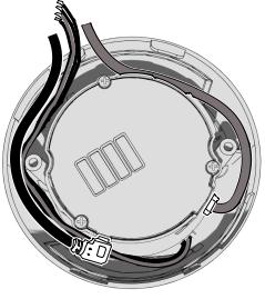
2.Connect the wiring to the side of the back box:
a.Connect the network cable to the RJ-45 network port on the side of the back box. Refer to Cat5 Cable on page 21 for wiring connections.
NOTE: Do not use network cables with over-molded RJ-45 connectors. These connectors will not fit inside the surface mount ring.
b.Connect the necessary wiring for audio (refer to Audio Wiring on page 22).
c.Be sure to route all wiring around the inside edge of the surface mount ring.
Figure 7. Routing Wiring for Surface Installations
3.Apply power to the camera.
NOTE: If the camera is not connected to a DHCP server and DHCP is enabled, the configuration sequence might take up to five minutes to complete.
14 |
C2973M-B (1/10) |

4. Use 6-32 toggle bolts (not supplied) to attach the surface mount ring and back box to the mounting surface (refer to Figure 8).
Figure 8. Ceiling or Wall Installation
ìWall/Ceiling
î6-32 Toggle Bolts (not supplied)
ïBack Box
NOTE: For a concrete ceiling or wall installation, use 8-32 mounting hardware (not supplied; refer to Figure 9).
Figure 9. Concrete Ceiling or Wall Installation
ìWall/Ceiling
î8-32 Mounting Hardware (not supplied)
ïBack Box
5.Position the camera as needed (refer to Positioning the Camera on page 17).
6.Focus the lens (refer to Adjusting the Focus on page 18).
7.Install the plastic liner and lower dome (refer to Installing the Dome Liner and Lower Dome on page 19).
C2973M-B (1/10) |
15 |
4S STANDARD ELECTRICAL BOX
1. Attach the adapter ring to the 4S standard electrical box with two 8-32 x 1.00-inch Phillips flat-head screws (supplied; refer to Figure 10).
Figure 10. 4S Standard Electrical Box Installation
ìCeiling/Wall
î4S Standard Electrical Box
ïAdapter Ring
ñBack Box
ó#8 x 2.50-inch Phillips Pan-Head Self-Tapping Screws (supplied)
r8-32 x 1.00-inch Phillips Flat-Head Screws (supplied)
2.Connect the wiring to the side of the back box:
a.Connect the network cable to the RJ-45 network port on the side of the back box. Refer to Cat5 Cable on page 21 for wiring connections.
NOTE: Do not use network cables with over-molded RJ-45 connectors. These connectors will not fit inside the surface mount ring.
b.Connect the necessary wiring for audio (refer to Audio Wiring on page 22).
3.Apply power to the camera.
NOTE: If the camera is not connected to a DHCP server and DHCP is enabled, the configuration sequence might take up to five minutes to complete.
4.Attach the surface mount ring and back box to the adapter plate with two #8 x 2.50-inch Phillips pan-head self-tapping screws (supplied; refer to Figure 10).
5.Position the camera as needed (refer to Positioning the Camera on page 17).
6.Focus the lens (refer to Adjusting the Focus on page 18).
7.Install the plastic liner and lower dome (refer to Installing the Dome Liner and Lower Dome on page 19).
16 |
C2973M-B (1/10) |

POSITIONING THE CAMERA
1.View the camera image using the service port.
2.Manually rotate and tilt the camera module to position the camera. Do not over-rotate the module.
 WARNING: Excessively turning the module in one direction could result in damage to the wiring.
Figure 11. Adjusting Pan and Tilt
ìPan 355°
îRotate 220°
ïTilt 180°
3.Adjust the field of view:
a.Loosen the zoom locking screw.
b.Turn the zoom adjustment ring clockwise or counterclockwise to adjust the field of view.
c.Tighten the zoom locking screw.
C2973M-B (1/10) |
17 |
ADJUSTING THE FOCUS
FOCUSING IMS0 SERIES MODELS
1.View the camera image using the service port.
2.Loosen the focus locking screw.
3.Turn the focus locking screw clockwise or counterclockwise to adjust the focus.
4.When the optimal focus is reached, tighten the focus locking screw.
FOCUSING IM10 SERIES MODELS
1.View the camera image using the service port or a Web browser.
2.Manually adjust the zoom and focus of the lens to the desired field of view.
3.The focus can be adjusted further using the settings in the Web interface (refer to Configuring Auto Focus Settings on page 44).
18 |
C2973M-B (1/10) |
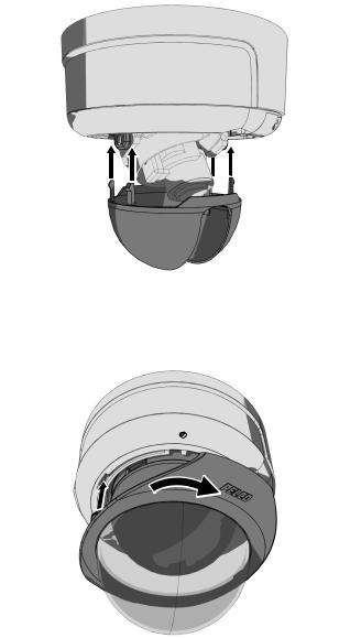
INSTALLING THE DOME LINER AND LOWER DOME
1. Align the dome liner with the camera module and snap it into place.
Figure 12. Installing the Dome Liner
2.Align the lower dome with the camera module, press it into place, and then turn it 45-degrees to conceal the service port, reset button, and NTSC/PAL button.
Figure 13. Installing the Lower Dome
C2973M-B (1/10) |
19 |
SERVICE CABLE
The dome camera includes a service port that outputs camera video. Use it at the installation site to set up the field of view and to focus the camera.
Pelco offers an optional service cable (IX-SC) that connects directly to the service port. To access the service port, you must remove the lower dome (refer to Installing the Dome Liner and Lower Dome on page 19). The service cable has a male BNC output for most standard viewers.
NOTE: The ICS-SC and CST150 are not compatible with this camera. If you have any questions about service cable compatibility, contact Pelco Product Support at 1-800-289-9100 (USA and Canada) or +1-559-292-1981 (international).
To assemble a service cable for the camera, you will need to purchase the following items from an electronics supply store:
Qty Description
1 2.5 mm stereo plug (male)
1 CPM 88 miniature coaxial connector
1 RG174/U coaxial cable
1 1/8-inch shrink fit tubing, 1/2-inch long
To assemble the cable:
1.Attach the CPM 88 miniature coaxial connector to one end of the cable. Follow the directions supplied with the miniature coaxial connector.
2.Attach the 2.5 mm stereo plug to the other end of the coaxial cable (refer to Figure 14):
a.Remove the support sleeve from the plug.
b.Slip the shrink fit tubing and support sleeve over the end of the cable.
c.Prepare the cable:
(1)Strip back the outer jacket 0.318 inch (8.06 mm) from the end of the cable.
(2)Pull back the coaxial braid shield.
(3)Strip back the insulating material 0.125 inch (3.18 mm) to expose the center conductor.
d.Solder the center connector of the cable to the center pin of the plug.
e.Pull the coaxial braid shield back through the crimp pin and solder it to the top of the crimp pin arm.
f.Crimp the end of the crimp pin around the cable.
g.Heat the shrink fit tubing around the center conductor and shoulder pin.
h.Reassemble the support sleeve and the plug.
Figure 14. Attaching the 2.5 mm Monaural Headphone Plug
ì2.5 mm Stereo Plug |
óShrink Fit Tubing |
îPlug Shoulder Pin |
rCoaxial Cable |
ïCenter Conductor |
sCoaxial Braid Shield |
ñSupport Sleeve |
tCrimp Pin Arm |
20 |
C2973M-B (1/10) |
WIRING
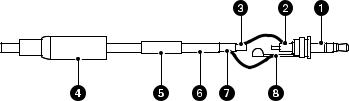
CAT5 CABLE
Connect a Cat5 cable to the RJ-45 network connector. The 8-pin connector includes video and PoE for the camera. PoE (IEEE 802.3af) injects power over the same cabling that carries the network data, eliminating the need for a separate power supply. This simplifies the installation and operation of the camera without affecting network performance.
NOTE: The camera will autosense and configure itself to use either a crossover cable or a straight cable.
Refer to Figure 15 for pin descriptions.
1 |
|
|
|
|
|
|
8 |
8 |
|
1 |
2 |
3 |
4 |
5 |
6 |
|
8 |
7 |
1 |
|
|
|
|
|
7 |
|
8 |
|
|
|
|
|
|
|
|
|
|
|
6 |
|
|
|
|
|
|
|
|
|
5 |
|
|
|
|
|
|
|
|
|
4 |
|
|
|
|
|
|
|
|
|
3 |
|
|
|
|
|
|
|
|
|
2 |
|
|
|
|
|
|
|
|
|
1 |
Pin |
Function |
|
|
1 |
TX+ |
|
|
2 |
TX– |
|
|
3 |
RX+ |
|
|
4 |
PoE 1-2 |
|
|
5 |
PoE 1-2 |
|
|
6 |
RX– |
|
|
7 |
PoE 3-4 |
|
|
8 |
PoE 3-4 |
|
|
Figure 15. Cat5 Cable Pin Descriptions
C2973M-B (1/10) |
21 |
AUDIO WIRING
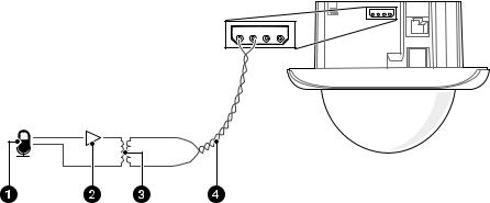
If you are not using the built-in microphone, the IM Series also supports line-in audio using standard UTP cable and a 600-ohm impedance matching transformer. Audio functionality is only available for IM10 Series models, and it can be enabled or disabled using the Web browser.
|
Figure 16. Line-In Audio Wiring |
ìMicrophone |
ï600-ohm Impedance Matching Transformer |
îAmplifier |
ñAudio UTP Cable |
22 |
C2973M-B (1/10) |

Operation
CAMERA CONFIGURATION SEQUENCE
Once the camera is installed and power is applied, the camera will start a configuration sequence: the green LED flashes five times per second for approximately two minutes and then glows solid green, indicating that the boot cycle is complete and the camera is on line.
NOTE: If the camera is not connected to a Dynamic Host Configuration Protocol (DHCP) server and DHCP is enabled, the configuration sequence might take up to five minutes to complete.
Refer to the following topics for more information:
•Network Tab on page 33
•Turning On DHCP on page 34
•Turning Off DHCP on page 34
MINIMUM SYSTEM REQUIREMENTS
Network and processor bandwidth limitations might cause the video stream to pause or appear pixilated when an increased number of Web-interface users connect to the camera. Decrease the images per second (ips), resolution, compression, or bit rate settings of the Web interface video streams to compensate for network/processor limitations.
The following minimum system requirements are needed to use a Web browser with the IP camera:
Processor: Intel® Pentium® 4 microprocessor, 1.6 GHz
Operating system: Microsoft® Windows® XP, Windows Vista®, or Mac® OS X 10.4
Memory: 512 MB RAM
Network interface card: 100 megabits (or greater)
Monitor: Minimum of 1024 x 768 resolution, 16or 32-bit pixel color resolution
Web browser: Internet Explorer® 7.0 (or later) or Mozilla® Firefox® 3.0 (or later)
Media Player: QuickTime® 7.6.5 for Windows XP, Windows Vista, or QuickTime 7.6.4 for Mac OS X 10.4 (or later)
NOTE: This product is not compatible with QuickTime version 7.6.4 for Windows XP, Windows Vista. If you have this version installed on your PC, upgrade to QuickTime version 7.6.5.
Refer to the following sections for more information:
•Compression Standards on page 52
•Available Camera Resolution on page 53
•Image Rate on page 53
•Bit Rate on page 53
C2973M-B (1/10) |
23 |
Loading...