


 Loading...
I N S T A L L A T I O N
ExSite® Enhanced Series
Explosionproof Camera
For EXP1230 (PTZ) Models
C1345M (11/18)
C1345M (11/18)
Important Safety Instructions . . . . . . . . . . . . . . . . . . . . . . . . . . . . . . . . . . . . . . . . . . . . . . . . . . . . . . . . . . . . . . . . . . . . . . . . . . . . . . . . . . . . . . . . . . . . 3
Standards, Certificates, and Warnings . . . . . . . . . . . . . . . . . . . . . . . . . . . . . . . . . . . . . . . . . . . . . . . . . . . . . . . . . . . . . . . . . . . . . . . . . . . . . . . . . . . . . 4
Standards . . . . . . . . . . . . . . . . . . . . . . . . . . . . . . . . . . . . . . . . . . . . . . . . . . . . . . . . . . . . . . . . . . . . . . . . . . . . . . . . . . . . . . . . . . . . . . . . . . . . . . . 4
Certificates . . . . . . . . . . . . . . . . . . . . . . . . . . . . . . . . . . . . . . . . . . . . . . . . . . . . . . . . . . . . . . . . . . . . . . . . . . . . . . . . . . . . . . . . . . . . . . . . . . . . . . 4
Warnings. . . . . . . . . . . . . . . . . . . . . . . . . . . . . . . . . . . . . . . . . . . . . . . . . . . . . . . . . . . . . . . . . . . . . . . . . . . . . . . . . . . . . . . . . . . . . . . . . . . . . . . . 4
Description. . . . . . . . . . . . . . . . . . . . . . . . . . . . . . . . . . . . . . . . . . . . . . . . . . . . . . . . . . . . . . . . . . . . . . . . . . . . . . . . . . . . . . . . . . . . . . . . . . . . . . . . . . . 6
Models . . . . . . . . . . . . . . . . . . . . . . . . . . . . . . . . . . . . . . . . . . . . . . . . . . . . . . . . . . . . . . . . . . . . . . . . . . . . . . . . . . . . . . . . . . . . . . . . . . . . . . . . . 6
Parts List . . . . . . . . . . . . . . . . . . . . . . . . . . . . . . . . . . . . . . . . . . . . . . . . . . . . . . . . . . . . . . . . . . . . . . . . . . . . . . . . . . . . . . . . . . . . . . . . . . . . . . . . 6
User Supplied Parts List . . . . . . . . . . . . . . . . . . . . . . . . . . . . . . . . . . . . . . . . . . . . . . . . . . . . . . . . . . . . . . . . . . . . . . . . . . . . . . . . . . . . . . . . . . . . 6
Installation . . . . . . . . . . . . . . . . . . . . . . . . . . . . . . . . . . . . . . . . . . . . . . . . . . . . . . . . . . . . . . . . . . . . . . . . . . . . . . . . . . . . . . . . . . . . . . . . . . . . . . . . . . . 7
Wire/Cable Connections . . . . . . . . . . . . . . . . . . . . . . . . . . . . . . . . . . . . . . . . . . . . . . . . . . . . . . . . . . . . . . . . . . . . . . . . . . . . . . . . . . . . . . . . . . . . . . . 11 Connecting an FSFP Module For Integrated Transmission (Fiber, etc). . . . . . . . . . . . . . . . . . . . . . . . . . . . . . . . . . . . . . . . . . . . . . . . . . . . . . . . 14 Installing an micro SD Card . . . . . . . . . . . . . . . . . . . . . . . . . . . . . . . . . . . . . . . . . . . . . . . . . . . . . . . . . . . . . . . . . . . . . . . . . . . . . . . . . . . . . . . . 15
Accessing the Camera . . . . . . . . . . . . . . . . . . . . . . . . . . . . . . . . . . . . . . . . . . . . . . . . . . . . . . . . . . . . . . . . . . . . . . . . . . . . . . . . . . . . . . . . . . . . . . . . . 16
Mounts. . . . . . . . . . . . . . . . . . . . . . . . . . . . . . . . . . . . . . . . . . . . . . . . . . . . . . . . . . . . . . . . . . . . . . . . . . . . . . . . . . . . . . . . . . . . . . . . . . . . . . . . . . . . . 17
Installation (Mounts) . . . . . . . . . . . . . . . . . . . . . . . . . . . . . . . . . . . . . . . . . . . . . . . . . . . . . . . . . . . . . . . . . . . . . . . . . . . . . . . . . . . . . . . . . . . . . . . . . . 18
WXM200 Wall Mount . . . . . . . . . . . . . . . . . . . . . . . . . . . . . . . . . . . . . . . . . . . . . . . . . . . . . . . . . . . . . . . . . . . . . . . . . . . . . . . . . . . . . . . . . . . . 18
CMXM200 Corner Mount Adapter . . . . . . . . . . . . . . . . . . . . . . . . . . . . . . . . . . . . . . . . . . . . . . . . . . . . . . . . . . . . . . . . . . . . . . . . . . . . . . . . . . . 19
PAXM200 Pole Mount Adapter . . . . . . . . . . . . . . . . . . . . . . . . . . . . . . . . . . . . . . . . . . . . . . . . . . . . . . . . . . . . . . . . . . . . . . . . . . . . . . . . . . . . . 20
PXM200 Pedestal Mount . . . . . . . . . . . . . . . . . . . . . . . . . . . . . . . . . . . . . . . . . . . . . . . . . . . . . . . . . . . . . . . . . . . . . . . . . . . . . . . . . . . . . . . . . . 21
Dimensions . . . . . . . . . . . . . . . . . . . . . . . . . . . . . . . . . . . . . . . . . . . . . . . . . . . . . . . . . . . . . . . . . . . . . . . . . . . . . . . . . . . . . . . . . . . . . . . . . . . . . . . . . 22
Schedule Document
This document cannot be changed without prior regulatory review.
C1345M (11/18) |
1 |
2 |
C1345M (11/18) |

Important Safety Instructions
1.Read these instructions.
2.Keep these instructions.
3.Heed all warnings.
4.Follow all instructions.
5.To reduce the risk of ignition of hazardous atmospheres, disconnect the equipment from the supply circuit before opening. Keep assembly tightly closed when in operation.
6.The maximum ambient temperature range is -76° to 140°F (-60° to 60°C).
7.Only use attachments/accessories specified by the manufacturer.
8.Refer all servicing to qualified service personnel. Servicing is required when the apparatus has been damaged in any way, such as powersupply cord or plug is damaged, liquid has been spilled or objects have fallen into the apparatus, the apparatus has been exposed to rain or moisture, does not operate normally, or has been dropped.
9.Installation should be done only by qualified personnel and conform to all local codes.
10.Use only installation methods and materials capable of supporting four times the maximum specified load.
11.Use stainless steel hardware to fasten the mount to outdoor surfaces.
12.CAUTION: Use Fasteners with yield stress greater than or equal to Class 70.
13.AN ALL-POLE MAINS SWITCH with a contact separation of at least 3 mm in each pole shall be incorporated in the electrical installation of the building.
14.A readily accessible disconnect device shall be incorporated in the building installation wiring.
15.CAUTION: These servicing instructions are for use by qualified service personnel only. To reduce the risk of electric shock do not perform any servicing other that contained in the operating instructions unless you are qualified to do so.
16.For Zones based installations, a certified flameproof “db,” “tb,” and IP66 sealing device, such as a stopping box with setting compound, shall be provided either in the flameproof enclosure or immediately at the entrance thereto.
17.Use wires suitable for at least 75°C. For ambient temperatures below 14°F ( -10°C) use field wiring suitable for both minimum and maximum ambient temperature.
18.For marine installations, ensure that the camera is installed at least 5 meters from the ship’s magnetic compass.
19.The AC Mains unit shall be connected to a circuit breaker rated maximum 15A or 20A.
20.This product requires a surge protector device (SPD) or surge arrestor as part of the installation to address transient overvoltages exceeding Overvoltage Category II, 2500 Vpk.
C1345M (11/18) |
3 |
Standards, Certificates, and Warnings
STANDARDS
EN 60079-0: 2012 / A11: 2013 |
IEC 60079-0: 2011 |
||
EN 60079-1: 2014 |
IEC 60079-1: 2014 |
||
EN 60079-28: 2015 |
IEC 60079-28: 2015 |
||
EN 60079-31: 2014 |
IEC 60079-31: 2013 |
||
UL 60079-0 6th |
CSA C22.2 |
No 60079.0: 2015 |
|
UL 60079-1 7th |
CSA C22.2 |
No 60079-1: 2016 |
|
UL 60079-31 |
2nd |
CSA C22.2 |
No 60079-31: 2015 |
UL 60079-28 |
2nd Ed |
CSA C22.2 |
No 60079-28: 2016 |
CERTIFICATES
CLASS I, ZONE 1, AEx db op pr IIC T6
AEx tb op pr IIIC T85°C
AEx db op is op pr IIC T6
AEx tb op is op pr IIIC T85°C
IECEx UL 17.0011X
Ex db op pr IIC T6 Gb X
Ex tb op pr IIIC T85°C Db X
Ex db op is op pr IIC T6 Gb X
Ex tb op is op pr IIIC T85°C Db X
DEMKO 17 ATEX 1834X
 0539
0539  II 2 G Ex db op pr IIC T6 Gb
 II 2 D ex tb op pr IIIC T85°C Db
 0539
0539  II 2 G Ex db op is op pr IIC T6 Gb
 II 2 D Ex tb op is op pr IIIC T85°C Db
WARNINGS
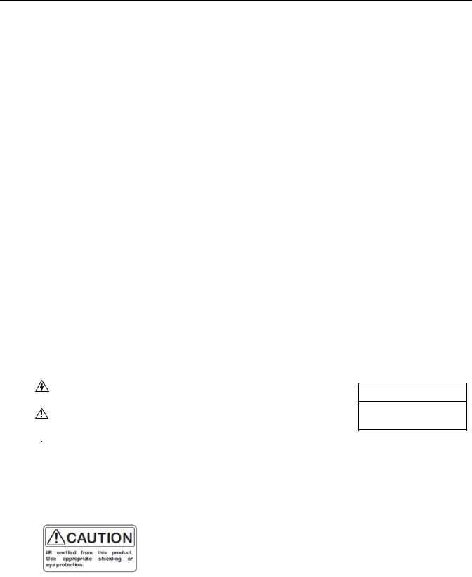
The product and/or manual may bear the following marks:
WARNING: This symbol indicates that dangerous voltage constituting a risk of electric shock is present within this unit.
This symbol indicates that there are important operating and maintenance instructions in the literature accompanying this unit.
 WARNING: HAZARDOUS MOVING PARTS. KEEP FINGERS AND OTHER BODY PARTS AWAY.
CAUTION:
RISK OF ELECTRIC SHOCK.
DO NOT OPEN.
 WARNING: Potential Electrostatic Charging Hazard
Clean the enclosure surface by gently wiping it with a damp, lint-free cloth before handling or performing maintenance.
 WARNING: Optical fiber cable must meet local codes and requirements for installation and connector must be secured by a latch.
 WARNING: Do not repair joints.
4 |
C1345M (11/18) |
WARNING: TO REDUCE THE RISK OF IGNITION OF HAZARDOUS ATMOSPHERES, DISCONNECT THE EQUIPMENT FROM THE SUPPLY CIRCUIT BEFORE OPENING. DO NOT OPEN WHEN AN EXPLOSIVE GAS/DUST ATMOSPHERE IS PRESENT. KEEP ASSEMBLY TIGHTLY CLOSED WHEN OPERATING. TO REDUCE THE RISK OF IGNITION OF HAZARDOUS ATMOSPHERES, ALL CONDUIT RUNSMUST HAVE A SEALING FITTING PLACED WITHIN 2” OF THE ENCLOSURE. REFER TO MANUAL FOR INSTALLATION.
PERIGO. PARA REDUZIR O RISCO DE IGNIÇÃO EM ATMOSFERAS POTENCIALMENTE EXPLOSIVAS DESCONECTE O EQUIPAMENTO DO SISTEMA DE ALIMENTAÇÃO ANTES DE ABRì-LO. MANTER O CONJUNTO CUIDADOSAMENTE FECHADO DURANTE A OPERAÇÃO TODOS OS CONDUITOS DEVEN POSSUIRUNIDADE SELADORA INSTALADA ATE 5.0CM DO INVOLUCRO PARA INSTALAÇÃO REFERIR SE O MANUAL.
AVERTISSEMENT: AFIN DE RÉDUIRE LE RISQUE D'INCENDIE DANS DES ATMOSPHÈRES DANGEREUSES, DÉBRANCHEZ L'ÉQUIPEMENT DU CIRCUIT ÉLECTRIQUE AVANT DE L'OUVRIR. NE PAS OUVRIR EN PRÉSENCE DE GAS EXPLOSIF OU DANS UNE ATMOSPHÈRE POUSSIÈREUSE. FERMEZ BIEN L'ASSEMBLAGE AVANT TOUTE UTILISATION. AFIN DE RÉDUIRE LE RISQUE D'INCENDIE DANS DES ATMOSPHÈRES DANGEREUSES, TOUS LES CONDUITS DOIVENT ÊTRE ÉQUIPÉS D'UN RACCORD D'ÉTANCHÉITÉ SITUÉ À 5,0 CM DU BOÎTIER. REPORTEZ-VOUS AU MANUEL POUR OBTENIR LES INSTRUCTIONS D'INSTALLATION.
C1345M (11/18) |
5 |

Description
ExSite® Enhanced Series is an explosionproof integrated positioning system with a built-in 1000Base-TX/100Base-TX network interface for live streaming using a standard Web browser. The integrated ExSite® Enhanced power module supplies power in 48 VDC or 100 to 240 VAC models.
MODELS
Model Number |
PTZ/Fixed |
Camera / Lens |
Input Voltage |
Illuminator |
EXP1230-4N |
|
1080p 30x |
48 VDC |
None |
EXP1230-7N |
PTZ |
1080p 30x |
100-240 VAC |
None |
|
|
|
|
|
EXP1230-7M |
|
1080p 30x |
100-240 VAC |
850 nm near-IR |
PARTS LIST
The following parts and tools are supplied:
Qty Description
1 ExSite Enhanced Series Explosion Proof Camera System
4 Bolts, M10 x 16 mm, stainless steel
4 Lock Washers
1 Custom Spanner Wrench
(NOTE: This tool is only used to open and close the wiring connection access door and the cap access door. The wiring connection access door and the cap access door are the only covers that are allowed to be opened.)
1 Power Connector
120-Pin Alarm/Relay Connector
1Ground Ring Terminal
1M4 x 8 mm Pan Head Slotted Ground Screw
11.5mm Hex Bit, 1/4" Shank
1Ferrite for Power Cable (Type 28A0640-0A2)
2Ferrites for Alarms/Relays and Ethernet Cables (Type 28A2024-0A2)
2M3 x 4mm Set Screws
112 - 28 AWG Splicing Connector
USER SUPPLIED PARTS LIST
You may or may not need a pipe nipple depending on the type of gland(s) you use. You will need one or two sealing glands depending on whether you use one or both of the unit’s cable entries. If using a single cable entry, you must provide a suitably-rated stopping plug for the other entry. Refer to the installation instructions for more information about plug selection.
1-2 Pipe Nipples, 3/4-inch NPT, 1-3/8-inch L
1 Conduit Sealing Fitting, 3/4-inch NPT, F/F, Metric Adapter (if needed) 1 Conduit Fitting Sealant
1 Safety Strap or Cable
1 3/4” NPT Conduit Plug (if not using both conduit entries)
For Zones based installations, the pipe nipple, stopping plug and/or conduit sealing fitting must be certified flameproof “db,” “tb,” and IP66, IP67, and IP68.
6 |
C1345M (11/18) |

Installation
Ensure that power is off before attempting to connect and wire the camera.
1.Attach a safety strap or cable (not supplied) in the hole shown below. Use a safety strap or cable during installation, when attaching the camera on a mount, or in case there is ever a screw or mount failure.
Safety Strap or Cable hole
Figure 1. Attach a Safety Strap or Cable in the Hole Shown Above
2.Attach the camera to the mounting surface. Use only installation methods and materials capable of supporting four times the maximum specified load of the system.
3.Make sure the threads on the underside of the camera and the threads of the four M10 x 16 mm stainless steel bolts (supplied) are free of dirt and debris.
4.Secure the camera to the mounting surface with the four M10 x 16 mm stainless steel bolts and lock washers (supplied).
C1345M (11/18) |
7 |
Loading...