


 Loading...
Pelco DSSRV-005-US, DSSRV-005DVD-US, DSSRV-030-US, DSSRV-030DVD-US, DSSRV-060-US Installation
...I N S T A L L A T I O N
Digital Sentry®
Network Video
Recorder
DSSRV, DSSRV-DVD
C4693M (10/11)
2 |
C4693M (10/11) |

Contents
Important Notices . . . . . . . . . . . . . . . . . . . . . . . . . . . . . . . . . . . . . . . . . . . . . . . . . . . . . . . . . . . . . . . . . . . . . . . . . . . . . . . . . . . . . . . . . . . . . . . . . . . . . 5
Legal Notice . . . . . . . . . . . . . . . . . . . . . . . . . . . . . . . . . . . . . . . . . . . . . . . . . . . . . . . . . . . . . . . . . . . . . . . . . . . . . . . . . . . . . . . . . . . . . . . . . . . . . 5
Regulatory Notices . . . . . . . . . . . . . . . . . . . . . . . . . . . . . . . . . . . . . . . . . . . . . . . . . . . . . . . . . . . . . . . . . . . . . . . . . . . . . . . . . . . . . . . . . . . . . . . . 5
Video Quality Caution . . . . . . . . . . . . . . . . . . . . . . . . . . . . . . . . . . . . . . . . . . . . . . . . . . . . . . . . . . . . . . . . . . . . . . . . . . . . . . . . . . . . . . . . . . . . . . 5
Description. . . . . . . . . . . . . . . . . . . . . . . . . . . . . . . . . . . . . . . . . . . . . . . . . . . . . . . . . . . . . . . . . . . . . . . . . . . . . . . . . . . . . . . . . . . . . . . . . . . . . . . . . . . 6
Optimized for Video Surveillance . . . . . . . . . . . . . . . . . . . . . . . . . . . . . . . . . . . . . . . . . . . . . . . . . . . . . . . . . . . . . . . . . . . . . . . . . . . . . . . . . . . . . 6
Reliability . . . . . . . . . . . . . . . . . . . . . . . . . . . . . . . . . . . . . . . . . . . . . . . . . . . . . . . . . . . . . . . . . . . . . . . . . . . . . . . . . . . . . . . . . . . . . . . . . . . . . . . 6
Open Architecture. . . . . . . . . . . . . . . . . . . . . . . . . . . . . . . . . . . . . . . . . . . . . . . . . . . . . . . . . . . . . . . . . . . . . . . . . . . . . . . . . . . . . . . . . . . . . . . . . 6
Features . . . . . . . . . . . . . . . . . . . . . . . . . . . . . . . . . . . . . . . . . . . . . . . . . . . . . . . . . . . . . . . . . . . . . . . . . . . . . . . . . . . . . . . . . . . . . . . . . . . . . . . . 7
Models . . . . . . . . . . . . . . . . . . . . . . . . . . . . . . . . . . . . . . . . . . . . . . . . . . . . . . . . . . . . . . . . . . . . . . . . . . . . . . . . . . . . . . . . . . . . . . . . . . . . . . . . . 7
Optional Accessories . . . . . . . . . . . . . . . . . . . . . . . . . . . . . . . . . . . . . . . . . . . . . . . . . . . . . . . . . . . . . . . . . . . . . . . . . . . . . . . . . . . . . . . . . . . . . . 7
Before You Begin . . . . . . . . . . . . . . . . . . . . . . . . . . . . . . . . . . . . . . . . . . . . . . . . . . . . . . . . . . . . . . . . . . . . . . . . . . . . . . . . . . . . . . . . . . . . . . . . . . . . . . 8
Package Contents . . . . . . . . . . . . . . . . . . . . . . . . . . . . . . . . . . . . . . . . . . . . . . . . . . . . . . . . . . . . . . . . . . . . . . . . . . . . . . . . . . . . . . . . . . . . . . . . . 8
Product Labels. . . . . . . . . . . . . . . . . . . . . . . . . . . . . . . . . . . . . . . . . . . . . . . . . . . . . . . . . . . . . . . . . . . . . . . . . . . . . . . . . . . . . . . . . . . . . . . . . . . 11
Product Serial Number Label Placement. . . . . . . . . . . . . . . . . . . . . . . . . . . . . . . . . . . . . . . . . . . . . . . . . . . . . . . . . . . . . . . . . . . . . . . . . . 11
IP Camera License Label . . . . . . . . . . . . . . . . . . . . . . . . . . . . . . . . . . . . . . . . . . . . . . . . . . . . . . . . . . . . . . . . . . . . . . . . . . . . . . . . . . . . . . 11
User Supplied Parts List . . . . . . . . . . . . . . . . . . . . . . . . . . . . . . . . . . . . . . . . . . . . . . . . . . . . . . . . . . . . . . . . . . . . . . . . . . . . . . . . . . . . . . . . . . . 11
Product Overview. . . . . . . . . . . . . . . . . . . . . . . . . . . . . . . . . . . . . . . . . . . . . . . . . . . . . . . . . . . . . . . . . . . . . . . . . . . . . . . . . . . . . . . . . . . . . . . . . . . . . 12
Rear Panel. . . . . . . . . . . . . . . . . . . . . . . . . . . . . . . . . . . . . . . . . . . . . . . . . . . . . . . . . . . . . . . . . . . . . . . . . . . . . . . . . . . . . . . . . . . . . . . . . . . . . . 12
Front Panel Controls and Indicators . . . . . . . . . . . . . . . . . . . . . . . . . . . . . . . . . . . . . . . . . . . . . . . . . . . . . . . . . . . . . . . . . . . . . . . . . . . . . . . . . . 13
Installation . . . . . . . . . . . . . . . . . . . . . . . . . . . . . . . . . . . . . . . . . . . . . . . . . . . . . . . . . . . . . . . . . . . . . . . . . . . . . . . . . . . . . . . . . . . . . . . . . . . . . . . . . . 15 Placing on a Desktop . . . . . . . . . . . . . . . . . . . . . . . . . . . . . . . . . . . . . . . . . . . . . . . . . . . . . . . . . . . . . . . . . . . . . . . . . . . . . . . . . . . . . . . . . . . . . 15 Mounting in a Rack. . . . . . . . . . . . . . . . . . . . . . . . . . . . . . . . . . . . . . . . . . . . . . . . . . . . . . . . . . . . . . . . . . . . . . . . . . . . . . . . . . . . . . . . . . . . . . . 15 Installing the Hard Drive Array . . . . . . . . . . . . . . . . . . . . . . . . . . . . . . . . . . . . . . . . . . . . . . . . . . . . . . . . . . . . . . . . . . . . . . . . . . . . . . . . . . . . . . 19 Installing the Hard Drive Carriers . . . . . . . . . . . . . . . . . . . . . . . . . . . . . . . . . . . . . . . . . . . . . . . . . . . . . . . . . . . . . . . . . . . . . . . . . . . . . . . 19 Connecting the Power Supply. . . . . . . . . . . . . . . . . . . . . . . . . . . . . . . . . . . . . . . . . . . . . . . . . . . . . . . . . . . . . . . . . . . . . . . . . . . . . . . . . . . . . . . 21 Connecting to the Network. . . . . . . . . . . . . . . . . . . . . . . . . . . . . . . . . . . . . . . . . . . . . . . . . . . . . . . . . . . . . . . . . . . . . . . . . . . . . . . . . . . . . . . . . 21
Startup and Shutdown. . . . . . . . . . . . . . . . . . . . . . . . . . . . . . . . . . . . . . . . . . . . . . . . . . . . . . . . . . . . . . . . . . . . . . . . . . . . . . . . . . . . . . . . . . . . . . . . . 22
Starting Up the Unit . . . . . . . . . . . . . . . . . . . . . . . . . . . . . . . . . . . . . . . . . . . . . . . . . . . . . . . . . . . . . . . . . . . . . . . . . . . . . . . . . . . . . . . . . . . . . . 22
Shutting Down the Unit . . . . . . . . . . . . . . . . . . . . . . . . . . . . . . . . . . . . . . . . . . . . . . . . . . . . . . . . . . . . . . . . . . . . . . . . . . . . . . . . . . . . . . . . . . . 22
Troubleshooting . . . . . . . . . . . . . . . . . . . . . . . . . . . . . . . . . . . . . . . . . . . . . . . . . . . . . . . . . . . . . . . . . . . . . . . . . . . . . . . . . . . . . . . . . . . . . . . . . . . . . . 23
Specifications . . . . . . . . . . . . . . . . . . . . . . . . . . . . . . . . . . . . . . . . . . . . . . . . . . . . . . . . . . . . . . . . . . . . . . . . . . . . . . . . . . . . . . . . . . . . . . . . . . . . . . . 24
Appendixes . . . . . . . . . . . . . . . . . . . . . . . . . . . . . . . . . . . . . . . . . . . . . . . . . . . . . . . . . . . . . . . . . . . . . . . . . . . . . . . . . . . . . . . . . . . . . . . . . . . . . . . . . 26 Appendix A: Installing an Uninterruptible Power Supply. . . . . . . . . . . . . . . . . . . . . . . . . . . . . . . . . . . . . . . . . . . . . . . . . . . . . . . . . . . . . . . . . . 26 Appendix B: Installing an Optional ENC5400 2-Port or 4-Port Capture Card . . . . . . . . . . . . . . . . . . . . . . . . . . . . . . . . . . . . . . . . . . . . . . . . . . . 27 Preparing and Installing the 2-PORT Capture Card . . . . . . . . . . . . . . . . . . . . . . . . . . . . . . . . . . . . . . . . . . . . . . . . . . . . . . . . . . . . . . . . . . 27 Preparing and Installing the 4-PORT Capture Card . . . . . . . . . . . . . . . . . . . . . . . . . . . . . . . . . . . . . . . . . . . . . . . . . . . . . . . . . . . . . . . . . . 28 Appendix C: Connecting to ENC5416 Units . . . . . . . . . . . . . . . . . . . . . . . . . . . . . . . . . . . . . . . . . . . . . . . . . . . . . . . . . . . . . . . . . . . . . . . . . . . . 30 Appendix D: Re-imaging the Unit . . . . . . . . . . . . . . . . . . . . . . . . . . . . . . . . . . . . . . . . . . . . . . . . . . . . . . . . . . . . . . . . . . . . . . . . . . . . . . . . . . . . 31 Recovery Process . . . . . . . . . . . . . . . . . . . . . . . . . . . . . . . . . . . . . . . . . . . . . . . . . . . . . . . . . . . . . . . . . . . . . . . . . . . . . . . . . . . . . . . . . . . . 32 Appendix E: Reconfiguring Monitor Resolutions . . . . . . . . . . . . . . . . . . . . . . . . . . . . . . . . . . . . . . . . . . . . . . . . . . . . . . . . . . . . . . . . . . . . . . . . 34 Appendix F: Installing AN Optional DSSRV-RAID Controller Card. . . . . . . . . . . . . . . . . . . . . . . . . . . . . . . . . . . . . . . . . . . . . . . . . . . . . . . . . . . 39 Preparing for RAID Controller Card Installation . . . . . . . . . . . . . . . . . . . . . . . . . . . . . . . . . . . . . . . . . . . . . . . . . . . . . . . . . . . . . . . . . . . . 39 Opening the Chassis . . . . . . . . . . . . . . . . . . . . . . . . . . . . . . . . . . . . . . . . . . . . . . . . . . . . . . . . . . . . . . . . . . . . . . . . . . . . . . . . . . . . . . . . . 39 Preparing the Unit for RAID Controller Card Installation . . . . . . . . . . . . . . . . . . . . . . . . . . . . . . . . . . . . . . . . . . . . . . . . . . . . . . . . . . . . . 40 Installing the RAID Controller Card . . . . . . . . . . . . . . . . . . . . . . . . . . . . . . . . . . . . . . . . . . . . . . . . . . . . . . . . . . . . . . . . . . . . . . . . . . . . . . 41 Completing the Installation . . . . . . . . . . . . . . . . . . . . . . . . . . . . . . . . . . . . . . . . . . . . . . . . . . . . . . . . . . . . . . . . . . . . . . . . . . . . . . . . . . . . 45 Appendix G: Installing an Optional DSSRV-SCSI Card. . . . . . . . . . . . . . . . . . . . . . . . . . . . . . . . . . . . . . . . . . . . . . . . . . . . . . . . . . . . . . . . . . . . 46 Preparing the DSSRV-SCSI Card . . . . . . . . . . . . . . . . . . . . . . . . . . . . . . . . . . . . . . . . . . . . . . . . . . . . . . . . . . . . . . . . . . . . . . . . . . . . . . . . 46 Opening the Chassis . . . . . . . . . . . . . . . . . . . . . . . . . . . . . . . . . . . . . . . . . . . . . . . . . . . . . . . . . . . . . . . . . . . . . . . . . . . . . . . . . . . . . . . . . 46 Installing the SCSI Card. . . . . . . . . . . . . . . . . . . . . . . . . . . . . . . . . . . . . . . . . . . . . . . . . . . . . . . . . . . . . . . . . . . . . . . . . . . . . . . . . . . . . . . 46 Completing the SCSI Card Installation . . . . . . . . . . . . . . . . . . . . . . . . . . . . . . . . . . . . . . . . . . . . . . . . . . . . . . . . . . . . . . . . . . . . . . . . . . . 47
C4693M (10/11) |
3 |

List of Illustrations
1 Major Package Components. . . . . . . . . . . . . . . . . . . . . . . . . . . . . . . . . . . . . . . . . . . . . . . . . . . . . . . . . . . . . . . . . . . . . . . . . . . . . . . . . . . . . . . . . 8 2 Accessory Pack . . . . . . . . . . . . . . . . . . . . . . . . . . . . . . . . . . . . . . . . . . . . . . . . . . . . . . . . . . . . . . . . . . . . . . . . . . . . . . . . . . . . . . . . . . . . . . . . . . . 9 3 Rack Mount Kit . . . . . . . . . . . . . . . . . . . . . . . . . . . . . . . . . . . . . . . . . . . . . . . . . . . . . . . . . . . . . . . . . . . . . . . . . . . . . . . . . . . . . . . . . . . . . . . . . . 10 4 Rear Panel Layout . . . . . . . . . . . . . . . . . . . . . . . . . . . . . . . . . . . . . . . . . . . . . . . . . . . . . . . . . . . . . . . . . . . . . . . . . . . . . . . . . . . . . . . . . . . . . . . . 12 5 DSSRV Front Panel Layout (Bezel Open). . . . . . . . . . . . . . . . . . . . . . . . . . . . . . . . . . . . . . . . . . . . . . . . . . . . . . . . . . . . . . . . . . . . . . . . . . . . . . . 13 6 DSSRV-DVD Front Panel Layout (Bezel Open) . . . . . . . . . . . . . . . . . . . . . . . . . . . . . . . . . . . . . . . . . . . . . . . . . . . . . . . . . . . . . . . . . . . . . . . . . . 13 7 Front Bezel Indicators (Bezel Closed) . . . . . . . . . . . . . . . . . . . . . . . . . . . . . . . . . . . . . . . . . . . . . . . . . . . . . . . . . . . . . . . . . . . . . . . . . . . . . . . . . 13 8 Support Rail Assembly . . . . . . . . . . . . . . . . . . . . . . . . . . . . . . . . . . . . . . . . . . . . . . . . . . . . . . . . . . . . . . . . . . . . . . . . . . . . . . . . . . . . . . . . . . . . 15 9 Removing the Chassis Brackets from the Sliding Brackets . . . . . . . . . . . . . . . . . . . . . . . . . . . . . . . . . . . . . . . . . . . . . . . . . . . . . . . . . . . . . . . . 16 10 Attaching the Mounting Brackets. . . . . . . . . . . . . . . . . . . . . . . . . . . . . . . . . . . . . . . . . . . . . . . . . . . . . . . . . . . . . . . . . . . . . . . . . . . . . . . . . . . . 16 11 Attaching the L-Shaped Mounting Brackets . . . . . . . . . . . . . . . . . . . . . . . . . . . . . . . . . . . . . . . . . . . . . . . . . . . . . . . . . . . . . . . . . . . . . . . . . . . 17 12 Attaching the Brackets to the Rack . . . . . . . . . . . . . . . . . . . . . . . . . . . . . . . . . . . . . . . . . . . . . . . . . . . . . . . . . . . . . . . . . . . . . . . . . . . . . . . . . . 17 13 Installing the Unit in the Rack . . . . . . . . . . . . . . . . . . . . . . . . . . . . . . . . . . . . . . . . . . . . . . . . . . . . . . . . . . . . . . . . . . . . . . . . . . . . . . . . . . . . . . 18 14 Aligning the Chassis Bracket and the Sliding Bracket . . . . . . . . . . . . . . . . . . . . . . . . . . . . . . . . . . . . . . . . . . . . . . . . . . . . . . . . . . . . . . . . . . . . 18 15 Numbered Hard Drive Bays for DSSRV . . . . . . . . . . . . . . . . . . . . . . . . . . . . . . . . . . . . . . . . . . . . . . . . . . . . . . . . . . . . . . . . . . . . . . . . . . . . . . . 19 16 Numbered Hard Drive Bays Plus Optical for DSSRV-DVD . . . . . . . . . . . . . . . . . . . . . . . . . . . . . . . . . . . . . . . . . . . . . . . . . . . . . . . . . . . . . . . . . 20 17 Opening the Bezel. . . . . . . . . . . . . . . . . . . . . . . . . . . . . . . . . . . . . . . . . . . . . . . . . . . . . . . . . . . . . . . . . . . . . . . . . . . . . . . . . . . . . . . . . . . . . . . . 20 18 Installing a Hard Drive Carrier . . . . . . . . . . . . . . . . . . . . . . . . . . . . . . . . . . . . . . . . . . . . . . . . . . . . . . . . . . . . . . . . . . . . . . . . . . . . . . . . . . . . . . 20 19 Closing and Locking a Hard Drive Carrier. . . . . . . . . . . . . . . . . . . . . . . . . . . . . . . . . . . . . . . . . . . . . . . . . . . . . . . . . . . . . . . . . . . . . . . . . . . . . . 21 20 Network Cable Connection. . . . . . . . . . . . . . . . . . . . . . . . . . . . . . . . . . . . . . . . . . . . . . . . . . . . . . . . . . . . . . . . . . . . . . . . . . . . . . . . . . . . . . . . . 21 21 Starting Up the Unit . . . . . . . . . . . . . . . . . . . . . . . . . . . . . . . . . . . . . . . . . . . . . . . . . . . . . . . . . . . . . . . . . . . . . . . . . . . . . . . . . . . . . . . . . . . . . . 22 22 Connecting a UPS to a DS NVR . . . . . . . . . . . . . . . . . . . . . . . . . . . . . . . . . . . . . . . . . . . . . . . . . . . . . . . . . . . . . . . . . . . . . . . . . . . . . . . . . . . . . 26 23 Removing the Filler Bracket: 2-Port Capture Card . . . . . . . . . . . . . . . . . . . . . . . . . . . . . . . . . . . . . . . . . . . . . . . . . . . . . . . . . . . . . . . . . . . . . . . 27 24 Installing the 2-Port Capture Card . . . . . . . . . . . . . . . . . . . . . . . . . . . . . . . . . . . . . . . . . . . . . . . . . . . . . . . . . . . . . . . . . . . . . . . . . . . . . . . . . . . 27 25 Removing the Filler Bracket: 4-Port Capture Card . . . . . . . . . . . . . . . . . . . . . . . . . . . . . . . . . . . . . . . . . . . . . . . . . . . . . . . . . . . . . . . . . . . . . . . 28 26 Installing the 4-Port Capture Card . . . . . . . . . . . . . . . . . . . . . . . . . . . . . . . . . . . . . . . . . . . . . . . . . . . . . . . . . . . . . . . . . . . . . . . . . . . . . . . . . . . 29 27 Connecting the DSSRV and ENC5416(s). . . . . . . . . . . . . . . . . . . . . . . . . . . . . . . . . . . . . . . . . . . . . . . . . . . . . . . . . . . . . . . . . . . . . . . . . . . . . . . 30 28 Recovery Warning Dialog Box . . . . . . . . . . . . . . . . . . . . . . . . . . . . . . . . . . . . . . . . . . . . . . . . . . . . . . . . . . . . . . . . . . . . . . . . . . . . . . . . . . . . . . 32 29 RAID Operations Dialog Box. . . . . . . . . . . . . . . . . . . . . . . . . . . . . . . . . . . . . . . . . . . . . . . . . . . . . . . . . . . . . . . . . . . . . . . . . . . . . . . . . . . . . . . . 32 30 JBOD Systems Dialog Box . . . . . . . . . . . . . . . . . . . . . . . . . . . . . . . . . . . . . . . . . . . . . . . . . . . . . . . . . . . . . . . . . . . . . . . . . . . . . . . . . . . . . . . . . 33 31 Reconfiguring Monitor Resolutions: Option One . . . . . . . . . . . . . . . . . . . . . . . . . . . . . . . . . . . . . . . . . . . . . . . . . . . . . . . . . . . . . . . . . . . . . . . . 34 32 Reconfiguring Monitor Resolutions: Option Two . . . . . . . . . . . . . . . . . . . . . . . . . . . . . . . . . . . . . . . . . . . . . . . . . . . . . . . . . . . . . . . . . . . . . . . . 34 33 Reconfiguring Monitor Resolutions: Option Three. . . . . . . . . . . . . . . . . . . . . . . . . . . . . . . . . . . . . . . . . . . . . . . . . . . . . . . . . . . . . . . . . . . . . . . 34 34 Selecting the Operating Mode . . . . . . . . . . . . . . . . . . . . . . . . . . . . . . . . . . . . . . . . . . . . . . . . . . . . . . . . . . . . . . . . . . . . . . . . . . . . . . . . . . . . . . 35 35 Selecting the Monitor. . . . . . . . . . . . . . . . . . . . . . . . . . . . . . . . . . . . . . . . . . . . . . . . . . . . . . . . . . . . . . . . . . . . . . . . . . . . . . . . . . . . . . . . . . . . . 35 36 Accepting Display Settings. . . . . . . . . . . . . . . . . . . . . . . . . . . . . . . . . . . . . . . . . . . . . . . . . . . . . . . . . . . . . . . . . . . . . . . . . . . . . . . . . . . . . . . . . 35 37 Selecting the Display Settings . . . . . . . . . . . . . . . . . . . . . . . . . . . . . . . . . . . . . . . . . . . . . . . . . . . . . . . . . . . . . . . . . . . . . . . . . . . . . . . . . . . . . . 36 38 Selecting Displays for Cloned Monitors. . . . . . . . . . . . . . . . . . . . . . . . . . . . . . . . . . . . . . . . . . . . . . . . . . . . . . . . . . . . . . . . . . . . . . . . . . . . . . . 36 39 Selecting Cloned Display Settings . . . . . . . . . . . . . . . . . . . . . . . . . . . . . . . . . . . . . . . . . . . . . . . . . . . . . . . . . . . . . . . . . . . . . . . . . . . . . . . . . . . 37 40 Complete the Wizard Dialog Box . . . . . . . . . . . . . . . . . . . . . . . . . . . . . . . . . . . . . . . . . . . . . . . . . . . . . . . . . . . . . . . . . . . . . . . . . . . . . . . . . . . . 37 41 Selecting Dual Monitor Resolutions. . . . . . . . . . . . . . . . . . . . . . . . . . . . . . . . . . . . . . . . . . . . . . . . . . . . . . . . . . . . . . . . . . . . . . . . . . . . . . . . . . 38 42 Identifying Monitors . . . . . . . . . . . . . . . . . . . . . . . . . . . . . . . . . . . . . . . . . . . . . . . . . . . . . . . . . . . . . . . . . . . . . . . . . . . . . . . . . . . . . . . . . . . . . . 38 43 Disconnecting SATA Cables from the Motherboard. . . . . . . . . . . . . . . . . . . . . . . . . . . . . . . . . . . . . . . . . . . . . . . . . . . . . . . . . . . . . . . . . . . . . . 40 44 Lifting the Backplanes . . . . . . . . . . . . . . . . . . . . . . . . . . . . . . . . . . . . . . . . . . . . . . . . . . . . . . . . . . . . . . . . . . . . . . . . . . . . . . . . . . . . . . . . . . . . 40 45 Disconnecting the SATA Cables . . . . . . . . . . . . . . . . . . . . . . . . . . . . . . . . . . . . . . . . . . . . . . . . . . . . . . . . . . . . . . . . . . . . . . . . . . . . . . . . . . . . . 41 46 Connecting the Multilane SATA Cables . . . . . . . . . . . . . . . . . . . . . . . . . . . . . . . . . . . . . . . . . . . . . . . . . . . . . . . . . . . . . . . . . . . . . . . . . . . . . . . 42 47 Seating the Backplanes . . . . . . . . . . . . . . . . . . . . . . . . . . . . . . . . . . . . . . . . . . . . . . . . . . . . . . . . . . . . . . . . . . . . . . . . . . . . . . . . . . . . . . . . . . . 42 48 Removing the PCIe x 16 Filler Bracket . . . . . . . . . . . . . . . . . . . . . . . . . . . . . . . . . . . . . . . . . . . . . . . . . . . . . . . . . . . . . . . . . . . . . . . . . . . . . . . . 43 49 Installing the RAID Controller Card . . . . . . . . . . . . . . . . . . . . . . . . . . . . . . . . . . . . . . . . . . . . . . . . . . . . . . . . . . . . . . . . . . . . . . . . . . . . . . . . . . 43 50 Running the Cables Through the Cable Slot. . . . . . . . . . . . . . . . . . . . . . . . . . . . . . . . . . . . . . . . . . . . . . . . . . . . . . . . . . . . . . . . . . . . . . . . . . . . 44 51 Connecting the Cables to the RAID Controller Card. . . . . . . . . . . . . . . . . . . . . . . . . . . . . . . . . . . . . . . . . . . . . . . . . . . . . . . . . . . . . . . . . . . . . . 44 52 Installing the Hard Drive Carriers . . . . . . . . . . . . . . . . . . . . . . . . . . . . . . . . . . . . . . . . . . . . . . . . . . . . . . . . . . . . . . . . . . . . . . . . . . . . . . . . . . . . 45 53 Removing the Metal Filler Bracket . . . . . . . . . . . . . . . . . . . . . . . . . . . . . . . . . . . . . . . . . . . . . . . . . . . . . . . . . . . . . . . . . . . . . . . . . . . . . . . . . . . 46 54 Installing the SCSI Card . . . . . . . . . . . . . . . . . . . . . . . . . . . . . . . . . . . . . . . . . . . . . . . . . . . . . . . . . . . . . . . . . . . . . . . . . . . . . . . . . . . . . . . . . . . 47
4 |
C4693M (10/11) |

Important Notices
LEGAL NOTICE
SOME PELCO EQUIPMENT CONTAINS, AND THE SOFTWARE ENABLES, AUDIO/VISUAL AND RECORDING CAPABILITIES, THE IMPROPER USE OF WHICH MAY SUBJECT YOU TO CIVIL AND CRIMINAL PENALTIES. APPLICABLE LAWS REGARDING THE USE OF SUCH CAPABILITIES VARY BETWEEN JURISDICTIONS AND MAY REQUIRE, AMONG OTHER THINGS, EXPRESS WRITTEN CONSENT FROM RECORDED SUBJECTS. YOU ARE SOLELY RESPONSIBLE FOR INSURING STRICT COMPLIANCE WITH SUCH LAWS AND FOR STRICT ADHERENCE TO ANY/ALL RIGHTS OF PRIVACY AND PERSONALTY. USE OF THIS EQUIPMENT AND/OR SOFTWARE FOR ILLEGAL SURVEILLANCE OR MONITORING SHALL BE DEEMED UNAUTHORIZED USE IN VIOLATION OF THE END USER SOFTWARE AGREEMENT AND RESULT IN THE IMMEDIATE TERMINATION OF YOUR LICENSE RIGHTS THEREUNDER.
REGULATORY NOTICES
This device complies with Part 15 of the FCC Rules. Operation is subject to the following two conditions: (1) this device may not cause harmful interference, and (2) this device must accept any interference received, including interference that may cause undesired operation.
RADIO AND TELEVISION INTERFERENCE
This equipment has been tested and found to comply with the limits of a Class A digital device, pursuant to Part 15 of the FCC rules. These limits are designed to provide reasonable protection against harmful interference when the equipment is operated in a commercial environment.
This equipment generates, uses, and can radiate radio frequency energy and, if not installed and used in accordance with the instruction manual, may cause harmful interference to radio communications. Operation of this equipment in a residential area is likely to cause harmful interference in which case the user will be required to correct the interference at his own expense.
Changes and Modifications not expressly approved by the manufacturer or registrant of this equipment can void your authority to operate this equipment under Federal Communications Commission’s rules.
In order to maintain compliance with FCC regulations shielded cables must be used with this equipment. Operation with non-approved equipment or unshielded cables is likely to result in interference to radio and television reception.
This Class A digital apparatus complies with Canadian ICES-003.
Cet appareil numérique de la classe A est conforme à la norme NMB-003 du Canada.
VIDEO QUALITY CAUTION
FRAME RATE NOTICE REGARDING USER-SELECTED OPTIONS
Pelco, Inc. systems are capable of providing high quality video for both live viewing and playback. However, the systems can be used in lower quality modes, which can degrade picture quality, to allow for a slower rate of data transfer and to reduce the amount of video data stored. The picture quality can be degraded by either lowering the resolution, reducing the picture rate, or both. A picture degraded by having a reduced resolution may result in an image that is less clear or even indiscernible. A picture degraded by reducing the picture rate has fewer frames per second, which can result in images that appear to jump or move more quickly than normal during playback. Lower frame rates may result in a key event not being recorded by the system.
Judgment as to the suitability of the products for users’ purposes is solely the users’ responsibility. Users should refer to the operation manuals for cautionary statements regarding user selected options and how they might affect video quality. Users shall determine the suitability of the products for their own intended application, picture rate and picture quality. The video analytic behaviors provide a large spectrum of settings that allow the behaviors to be used in a variety of applications. Selection of appropriate settings for proper detection in user applications is the sole responsibility of users. This equipment is intended to assist users in identifying situations of interest to users. Users have the sole responsibility of determining the appropriate response. In the event users intend to use the video for evidentiary purposes in a judicial proceeding or otherwise, users should consult with their attorney regarding any particular requirements for such use.
C4693M (10/11) |
5 |

Description
OPTIMIZED FOR VIDEO SURVEILLANCE
The new Digital Sentry® network video recorder (NVR) is optimized by Pelco to deliver the essential hardware support for the DS NVs video management software (VMS) without the extra cost or risk of integrating hardware and software.
Boosted by the 2nd Generation Intel® Core™ i7 processor and 8 GB of RAM, Digital Sentry NVR provides an optimal combination of processing power and reliability to meet the demands of HD video recording and playback operations. The system is powered to support up to 128 combined IP and analog video streams, with up to 64 analog cameras supported through the optional ENC5416 direct-attached encoder. Analog cameras are also supported using Pelco and third-party network video encoders.
The new DS NVR delivers total available throughput of 280 Mbps for recording of analog and IP video streams as well as playback and export through the DS ControlPoint client. When determining the maximum number of cameras and the desired frame rate to host on each system, the number of concurrent client connections, the number of streams likely to be viewed in playback on each client, and the bandwidth required to support the client connections must be taken into consideration.*
The DS NVR functions as a stand-alone system or as part of a network of servers, monitored from the DS ControlPoint user interface. The system can be deployed solely as a network video recorder, as a digital video recorder (DVR), or as a hybrid NVR.
Two gigabit network ports provide for convenient network architecture planning by allowing one port to be dedicated to IP cameras, while the second nework port is used for client connections. Two DVI-D ports provide a convenient connection for high resolution digital monitors for use with HD cameras.
RELIABILITY
With front-accessible drives for easy servicing and upgrades, the DS NVR is available with up to 18 TB for models without the optional optical disk drive (ODD), or up to 12 TB for ODD models. The drives are hot-swappable when configured for internal RAID 5 storage with the optional RAID 5 controller card. A minimum of three drives is required for a RAID 5 configuration. External storage is supported through USB attached storage or by using the optional DSSRV-SCSI interface card connected to DX8100HDDI storage of up to 24 TB. The external storage can be configured for JBOD storage or RAID 5. Internal RAID 5 storage cannot be used in conjunction with external storage.
Front panel LED displays on the DS NVR provide heads-up information on system operation. The LEDs are integrated with the Digital Sentry System Information (DSSI) utility, providing critical, real-time statistics on system resource utilization, temperature, and throughput status.
OPEN ARCHITECTURE
The cornerstone of Digital Sentry design, a fully Open Architecture, is provided through ONVIF compliance and support for a large number of IP-specific drivers. Users can choose specific IP cameras or encoders to fit their application.
Eliminate the risk of deferred support that comes with VMS software from one vendor and a general purpose hardware platform from another. Replace it with the assurance of an integrated platform built specifically for the rigors of IP video recording. Make the performance, reliability, and Open Architecture of DS NVs running on DS NVR the core foundation of your video management solution.
*Refer to the DS NVR Throughput Utilization Chart for references on typical bandwidth consumption rates. The chart is available at www.pelco.com on the Digital Sentry product page.
6 |
C4693M (10/11) |
FEATURES
•Provides 280 Mbps to support IP and analog video
•Supports up to 128 IP camera streams; up to 64 analog cameras*
•Optimized to support pre-installed DS NVs software
•Records H.264, MJPEG, and MPEG-4 IP streams
•Supports Pelco and third-party IP cameras and network encoders
•Expandable by networking an unlimited number of servers and encoders
•Compatible with DS ControlPoint for simultaneous monitoring of all DS Series and DX Series products in a single client interface
•Network health and event monitoring support through Simple Network Management Protocol (SNMP) and the Digital Sentry System Information (DSSI) utility
•Compatible with the DS Archive Utility
•Recording rate configurable per individual camera
•Support for DS DataPoint Integration
*Concurrent client connections, number of playback streams per client, and required bandwidth for client connections must be considered when determining maximum cameras and frame rate to host on each system.
MODELS
The following table describes the Digital Sentry NVR (DSSRV/DSSRV-DVD) model numbers. For example, the model number for a DS NVR with 12 TB and a United Kingdom power cord is DSSRV-120-UK. The model number for a DSSRV-DVD with 6 TB and an Australian power cord is DSSRV-060DVD-AU.
NOTE: Units shipped to China do not include power cords.
Table A. Models
Model |
|
Storage* |
Country Code |
|
|
|
|
|
Unit Without Optical Disk Drive |
||
|
|
|
|
DSSRV-005 |
|
500 GB |
|
|
|
|
|
DSSRV-030 |
|
3 TB |
US = North America |
|
|
|
EU = Europe |
DSSRV-060 |
|
6 TB |
|
|
|
|
UK = United Kingdom |
DSSRV-090 |
|
9 TB |
|
|
CN = China |
||
|
|
|
|
DSSRV-120 |
|
12 TB |
|
|
AU = Australia |
||
|
|
|
|
DSSRV-150 |
|
15 TB |
AR = Argentina |
|
|
|
|
DSSRV-180 |
|
18 TB |
|
|
|
|
|
Model |
Storage* |
Country Code |
|
|
|
|
|
Unit With Optical Disk Drive |
|||
|
|
|
|
DSSRV-005DVD |
500 GB |
US = North America |
|
DSSRV-030DVD |
3 TB |
EU = Europe |
|
|
|
UK = United Kingdom |
|
DSSRV-060DVD |
6 TB |
||
CN = China |
|||
|
|
||
DSSRV-090DVD |
9 TB |
||
AU = Australia |
|||
|
|
||
DSSRV-012DVD |
12 TB |
AR = Argentina |
|
|
|
|
|
*Storage capacities are subject to change. Contact Pelco Product Support for current capacity information.
OPTIONAL ACCESSORIES
DS-SW-CAM |
Models include eight licenses for Pelco and third party IP cameras; additional DS-SW-CAM licenses can be |
|
purchased separately |
ENC5416 |
Direct-attached analog encoder |
ENC5400-2PORT |
Analog 2-port host card connects two ENC5416 for up to 32 analog channels |
ENC5400-4PORT |
Analog 4-port host card connects four ENC5416 for more than 32 analog channels |
DSSRV-RAID |
LSI 3Ware 9750-8i RAID controller card |
DSSRV-SCSI |
Adaptec® SCSI Card 29320LPE |
KBD5000 Series |
Desktop keyboard with three control pods (recommended for analog keyboard requirements) |
C4693M (10/11) |
7 |
Before You Begin
PACKAGE CONTENTS
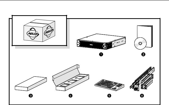
Figure 1. Major Package Components
ì
î
ï
ñ
ó
r
Network Video Recorder (DSSRV)
DSSRV-LIT Literature Kit: Includes Important Safety Instructions, Safe Handling of Hard Drives manual, resource disc, and recovery disc
NOTE: Refer to Appendix C: Connecting to ENC5416 Units on page 30 for NVR units.
Accessory Pack
Hard Drive Pack (hard drives in carriers)
NOTE: Number of hard drives depends on model.
Standard USB Keyboard (1 ea.)
Rack Mount Kit (1 ea.)
8 |
C4693M (10/11) |

Figure 2. Accessory Pack
ì
î
ï
ñ
Standard USB Mouse (1 ea.)
Bezel Keys (2 ea.)
Standard US Power Cord (1 ea.)
Power Cord (based on country designation, 1 ea.)
NOTE: Units shipped to China do not include power cords.
óChassis Handles (2 ea.)
NOTE: Includes Phillips screws for installation.
r Rubber Feet (4 ea.)
C4693M (10/11) |
9 |
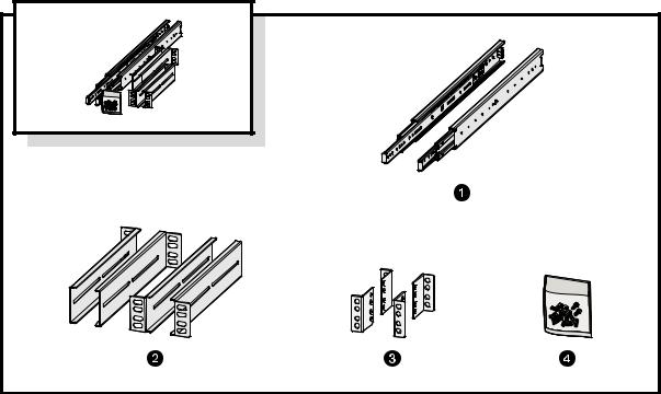
Figure 3. Rack Mount Kit
ì Sliding Mounting Brackets (2 ea.)
îRear Mount Rails (2 ea.), Front Mount Rails (2 ea.)
ï L-Shaped Plate Nuts (4 ea.)
ñM5*8L-H2.5 Round Head Nickel Screws (18 ea.), M4*6L-H2.5 Round Head Nickel Screws (18 ea.), 4.2*11*0.8 Nickel Washers (10 ea.)
10 |
C4693M (10/11) |
PRODUCT LABELS
PRODUCT SERIAL NUMBER LABEL PLACEMENT
Product serial number labels help identify your system and its factory configuration if your unit or its components should require service.
Three labels citing your product’s serial number are attached to the unit. One label is attached to the upper-right corner of the rear of the unit. A second, smaller label is attached to the inside left of the bezel.
Because rack mounting and other installation options may obscure the factory-applied labels, a third set of labels is provided for you to attach to your product documentation or to another product location that will not be obscured by installation.
To use these labels:
1.Locate the small label attached to the outside of the front bezel, attached with a yellow sticker that reads, “Extra serial number label: remove prior to installation.”
2.Remove the yellow sticker.
3.Peel away the backing of the small label, and then attach it to this manual, other product documentation, or an unobstructed product location.
IP CAMERA LICENSE LABEL
If you have ordered a license for additional IP cameras, a label will be placed on the inside left of the bezel. This label contains the key you will use to access the additional IP cameras through DS Quick Setup.
USER SUPPLIED PARTS LIST
The following installation tools and parts are needed for installation, but not supplied.
•Power source (110/220 VAC)
•Small Phillips screwdriver, if mounting the unit into a rack
•Uninterruptible power supply (UPS)
C4693M (10/11) |
11 |
Product Overview
REAR PANEL
Familiarize yourself with your respective unit's rear panel before connecting any equipment to the unit.
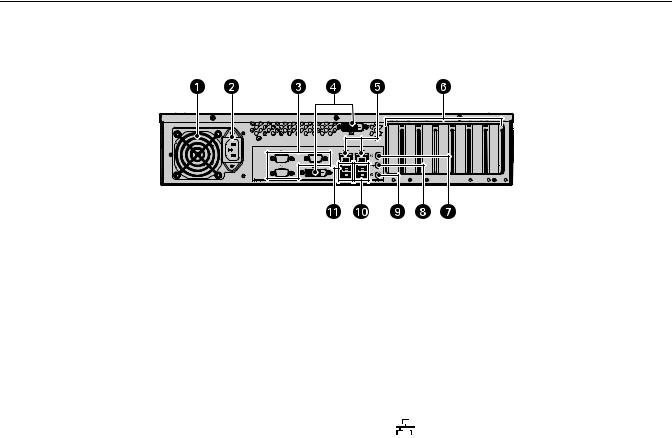
Figure 4. Rear Panel Layout
ì
î
ï
ñ
ó
r s t u ~í ~â
Rear Chassis Fan
Power Receptacle
Reserved (do not use)
Digital Visual Interface (DVI) connectors
•DVI-D1 (primary)
•DVI-D2 (secondary)
Ethernet Ports
•Network Port 1 (left is primary)
•Network Port 2 (right is secondary) 
Card Slots
Reserved (do not use)
Audio Out
Reserved (do not use)
USB 3.0 Ports
USB 2.0 Ports
12 |
C4693M (10/11) |

FRONT PANEL CONTROLS AND INDICATORS
Figure 5. DSSRV Front Panel Layout (Bezel Open)
Figure 6. DSSRV-DVD Front Panel Layout (Bezel Open)
Digital Sentry
DS SRV Series
Figure 7. Front Bezel Indicators (Bezel Closed)
ìUnit Status 
Unit status is indicated by one of the following three colors:
•Green: The unit is functioning normally.
•Flashing green: The unit is starting or shutting down.
•Amber: The unit is nearing operational thresholds; maintenance is recommended.
•Red: The unit is in an error condition (refer to Troubleshooting on page 23).
îNetwork Port 1 Speed and Activity 
Network status (connection and speed) is indicated by one of the following conditions:
•Off: The unit is not connected to the network.
•Solid green: The unit is connected to the network using the 1000Base-T standard.
•Solid amber: The unit is connected to the network using the 100Base-T standard.
•Solid red: The unit is connected to the network using the 10Base-T standard.
NOTE: For proper operation, you must use the 1000Base-T standard.
C4693M (10/11) |
13 |
ïNetwork Port 2 Speed and Activity 
Network status (connection and speed) is indicated by one of the following conditions:
•Off: The unit is not connected to the network.
•Solid green: The unit is connected to the network using the 1000Base-T standard.
•Solid amber: The unit is connected to the network using the 100Base-T standard.
•Solid red: The unit is connected to the network using the 10Base-T standard.
NOTE: For proper operation, you must use the 1000Base-T standard.
ñSoftware Status 
•Green: The software is operating normally.
•Amber: A minor software malfunction is detected (for example, an excessive network packet loss).
•Red: A fatal software error has occurred (for example, ceasing to record).
óPower Button 
•Push the power button to turn the unit on or off.
•Push and hold the power button for a hard shutdown.
rDrive Status
The drive status indicator reports the operating status of each individual hard drive as follows:
•Flashing green: The read or write activity on a specific hard drive.
•Solid red: A problem exists with the hard drive.
•Flashing green/red: The unit is initializing the hard drive.
sUSB Ports
The Digital Sentry NVR supports five USB ports: one on the front panel (one USB 2.0 port) and four on the rear panel (two USB 3.0 ports and two USB 2.0 ports). These ports can be used to connect a UPS unit, or it can be used to conduct diagnostic and troubleshooting activities.
14 |
C4693M (10/11) |
Installation
PLACING ON A DESKTOP
 WARNING: Do not place the unit on its side; in this position, the unit is likely to fall over and may cause equipment damage or personal injury.
To install the unit on a desktop:
1.Make sure the rubber feet are installed to prevent damage. If not, secure each rubber foot to the bottom panel of the unit.
2.Position the unit to allow for cable and power cord clearance at the rear of the unit.
MOUNTING IN A RACK
The unit can be mounted in an industry standard 48 cm (19-inch) equipment rack and occupies 2 rack units (RU) of vertical rack space (8.9 cm or 3.5 inches). The hardware necessary to mount the unit into a rack is supplied with the unit.
NOTE: The unit must be placed on a desktop to install an optional 2-Port or 4-Port capture card, a RAID controller card, or a SCSI card. Make sure these cards are installed properly and performing as expected before placing the unit in the rack.
The rack must meet the following requirements:
•Rack standard: 48 cm (19 inches), EIA-310-D compliant (rear column required)
•Rack column depth: 50.8 to 76.2 cm (20 to 30 inches)
•Column mounting hole provisions: 10-32 UNF-2B threaded holes or square window holes on front and rear columns
•Door systems (optional): Front doors must have at least 5.1 cm (2 inches) between the unit bezel and the inside of the door.
Rear doors may be used only on rack columns that are more than 66 cm (26 inches) deep.
 WARNINGS:
•Secure the front and rear screws to the support rails.
•Make sure the unit is level.
Slots and openings in the cabinet provide ventilation to prevent the unit from overheating. Do not block these openings. Never place the unit near or over a radiator or heat register. When placing the unit in a rack, be sure to provide proper ventilation.
NOTE: Refer to Figure 3 on page 10 for the description of the hardware used in this installation.
Figure 8 shows the support rail assembly items.
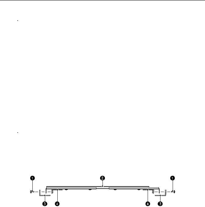
Figure 8. Support Rail Assembly
ì M5*8L-H2.5 Round Head Nickel Screws
î Mounting Bracket (sliding bracket attached to L-shaped brackets)
ï Rack
ñ L-Shaped Plate Nut
C4693M (10/11) |
15 |
Loading...