

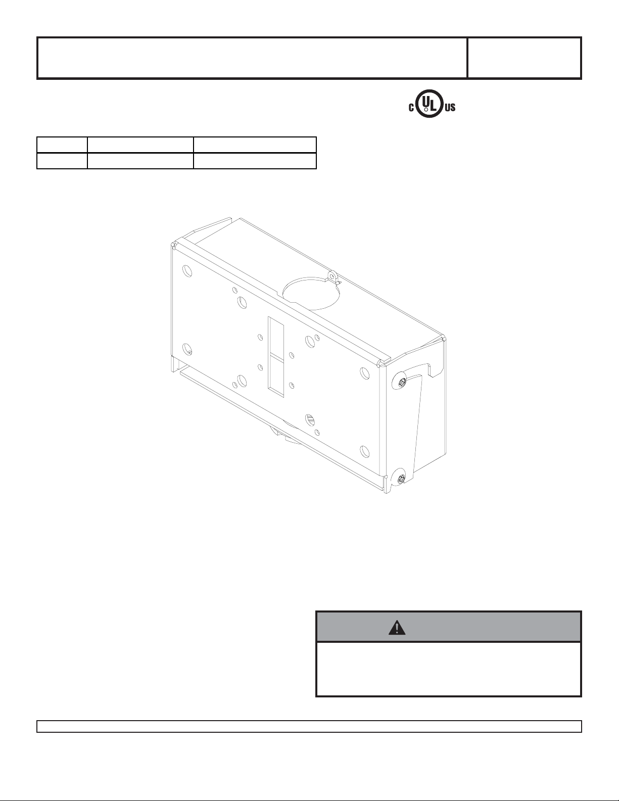
Installation and Assembly -
Solid•Point
™
Flat Panel Straight
Column Mount
Model:PLCM 2
Read instruction sheet before you start installation and assembly.
Mode l Ma x. Load Screen Siz e Ra nge
PLCM -2 225 lb. (102.3 k g . ) 32'' to 71''
This product is intended for use with UL
R
Listed products and must be installed by a
qualified professional installer.
Note: Installation for 32" - 71" LCD and Flat Panel Screens
WARNING
• Installer must verify that the supporting surface will
safely support the combined weight of all attached
equipment and hardware.
1 of 5
Visit the Peerless Web Site at www.peerlessmounts.com For customer care call 1-800-729-0307 or 708-865-8870.
ISSUED:02-14-03 SHEET #: 201-9019-8 03-29-07
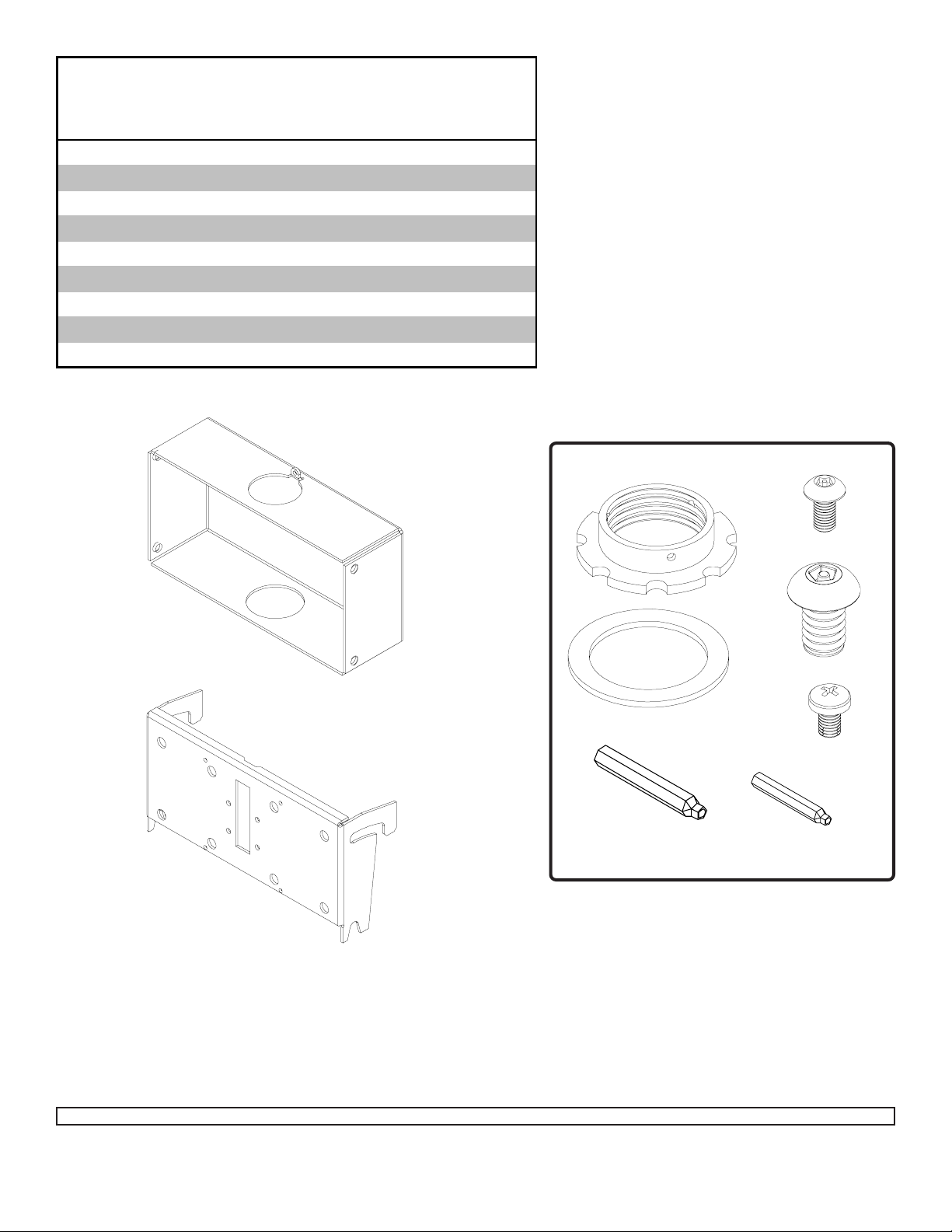
Before you begin, m ake sure all parts shown are included with y our product.
PARTS LIST
Description Qty Part #
ceiling arm box 1 201-1062
A
tilt bracket 1 200-1552
B
retaining collar 1 1800-375
D
M5 x .8 x 10 mm penta-pin™ screw 4 505-9010
E
2.875 OD x 2.125 ID x .062 H fi ber washer 1 540-9432
F
M10 x 1.5 x 15 mm penta-pin screw 8 520-9263
G
M10 x 2" penta-pin tool 1 520-9260
H
M5 x 1" penta-pin tool 1 520-9249
I
M5 x .8 x 8 mm phillips Type F screw 4 520-1167
J
A
B
F
H
Fasteners
D
E
G
J
I
Note: Some parts may not appear exactly as illustrated.
2 of 5
Visit the Peerless Web Site at www.peerlessmounts.com For customer care call 1-800-729-0307 or 708-865-8870.
ISSUED:02-14-03 SHEET #: 201-9019-8 03-29-07

Thread support pipe (schedule 40 pipe, 1.5 x 11.5 NPT, not included) into threaded fitting in ceiling plate
(UL Listed CMJ470, not included). Tighten - four or five complete turns - leaving slot aligned with one small hole in
the side of the ceiling plate threaded fitting. Insert and tighten one M5 x .8 x 10 mm penta-pin screw (E) provided
with ceiling plate as shown. Use the M5 penta-pin tool (I) to tighten screw. BY HAND, insert four M10 x 1.5 x 15
mm penta-pin screws (G) into threaded holes in the sides of ceiling arm box (A). Leave approximately 1/4" of
exposed thread. Slide ceiling arm box (A) and fiber washer (F) onto end of support pipe. Thread retaining collar (D)
onto threaded end of support pipe. Tighten - four or five complete turns. Slide ceiling arm box (A) down so that it
is on top of retaining collar (D). Insert and tighten one M5 x .8 x 10 mm penta-pin screw (E) into retaining collar (D)
as shown. Insert one M5 penta-pin screw (E) through the tab on the back of ceiling arm box (A). Use M5 pentapin tool (I) to tighten screw just enough to stabilize support pipe.
Note: UL Listed ADJ or EXT extension column series can be used in combination with, or in place of support
pipe to achieve different lengths.
ceiling plate (not included)
D
support pipe (not included)
A
F
E
E
BACK OF CEILING
ARM BOX
G
G
D
1/4"
E
3 of 5
Visit the Peerless Web Site at www.peerlessmounts.com For customer care call 1-800-729-0307 or 708-865-8870.
ISSUED:02-14-03 SHEET #: 201-9019-8 03-29-07

Note: Refer to adapter plate instruction sheet (sold separately , not UL evaluated) for attachment of adapter plate to
plasma before proceeding with step 2.
For LCD screen adapter bracket, skip to step 2 on page 5.
Attach tilt bracket (B) to adapter plate using four M10 x 15 mm penta-pin screws (G) in accordance with appropriate drawing below. T ighten using M10 penta-pin tool (H).
PLASMA SCREEN
ADAPTER PLATE
B
Note: Screen and adapter
plate may appear different
LANDSCAPE
Hang tilt bracket (B) onto ceiling arm box (A).
Adjust tilt as desired and tighten four M10 x 1.5 x
15 mm penta-pin screws (G) securely using M10
penta-pin tool (H).
than illustrated.
LANDSCAPE
PLASMA SCREEN
ADAPTER PLATE
G
B
G
PORTRAIT
(NOT to be used with UNL models)
WARNING
• For a safe assembly be sure to fully tighten four
screws (G).
• Do not mount PLCM-UNL in portrait orientation.
Mounting PLCM-UNL in portrait orientation may result
in product failure.
WARNING
A
A
G
B
LANDSCAPE PORTRAIT
4 of 5
Visit the Peerless Web Site at www.peerlessmounts.com For customer care call 1-800-729-0307 or 708-865-8870.
B
(NOT to be used with UNL models)
ISSUED:02-14-03 SHEET #: 201-9019-8 03-29-07
G

Note: Refer to adapter bracket instruction sheet (sold separately, not evaluated by UL) for att achment of adapter bracket to
LCD screen before proceeding with step 2.
Attach tilt bracket (B) to adapter bracket using four M5 x 8 mm phillips screws (J).
Note: Do not use M5 x 6 mm screws that are included with the adapter bracket
LCD SCREEN
ADAPTER BRACKET
B
Note: Screen and adapter
plate may appear different
than illustrated.
Hang tilt bracket (B) onto ceiling arm box (A). Adjust tilt as desired and tighten four
M10 x 1.5 x 15 mm penta-pin screws (G) securely using M10 penta-pin tool (H).
WARNING
• For a safe assembly be sure to fully tighten four
screws (G).
B
J
A
5 of 5
Visit the Peerless Web Site at www.peerlessmounts.com For customer care call 1-800-729-0307 or 708-865-8870.
ISSUED:02-14-03 SHEET #: 201-9019-8 03-29-07
G
 Loading...