

Installation and Assembly:
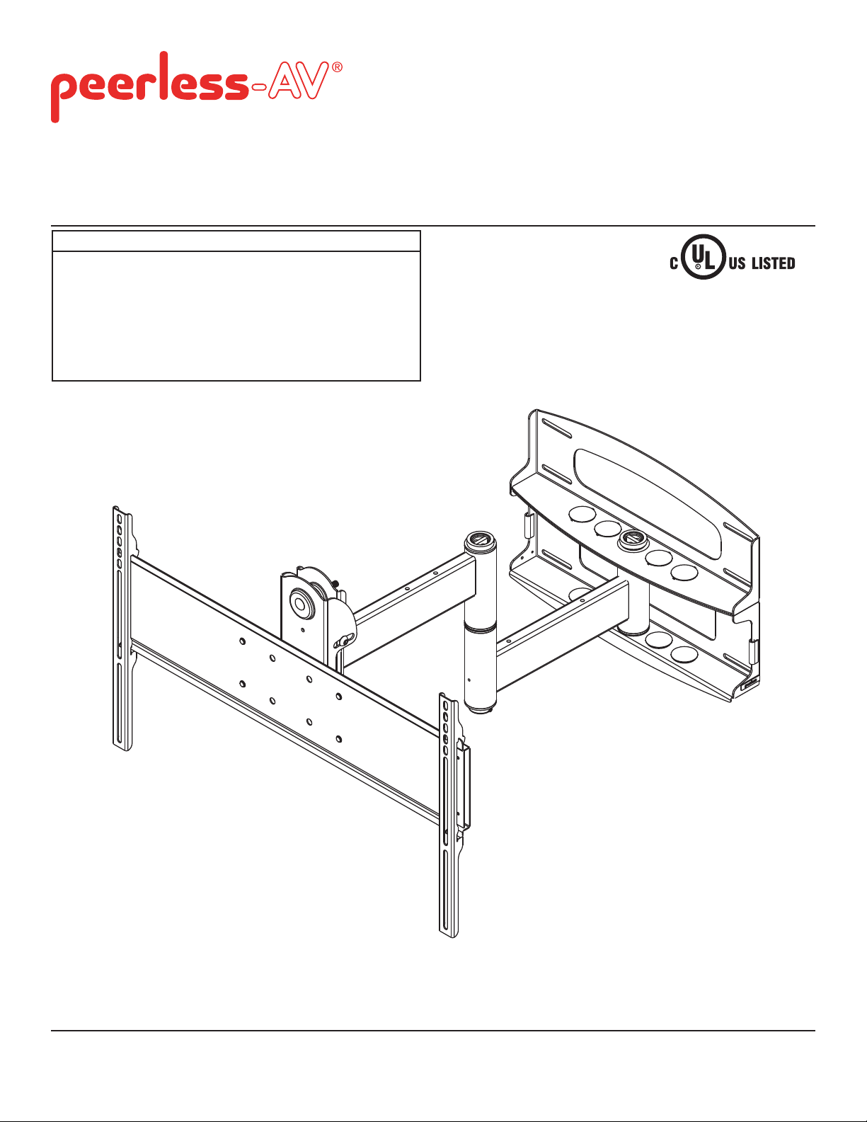
Universal Articulating Swivel Arm for 37" - 65" Flat Panel
Displays
Models
PLA60-UNL, PLA60-UNL-S,
PLA60-UNLP, PLA60-UNLP-S,
PLAV60-UNL, PLAV60-UNL-S,
PLAV60-UNLP, PLAV60-UNLP-S,
PLA60-UNLP-GB, PLA60-UNLP-GS,
PLAV60-UNLP-GB, PLAV60-UNLP-GS
Max UL Load Capacity:
175 lb (79 kg)
2300 White Oak Circle • Aurora, Il 60502 • (800) 865-2112 • Fax: (800) 359-6500 • www.peerless-av.com
ISSUED: 06-05-06 SHEET #: 202-9141-11 (2013-10-01)
Note: Read entire instruction sheet before you start installation and assembly.
WARNING
• Do not begin to install your Peerless product until you have read and understood the instructions and warnings
contained in this Installation Sheet. If you have any questions regarding any of the instructions or warnings, for US
customers please call Peerless customer care at 1-800-865-2112, for all international customers, please contact
your local distributor.
• This product should only be installed by someone of good mechanical aptitude, has experience with basic building
construction, and fully understands these instructions.
• Make sure that the supporting surface will safely support the combined load of the equipment and all attached
hardware and components.
• Never exceed the Maximum Load Capacity. See page one.
• If mounting to wood wall studs, make sure that mounting screws are anchored into the center of the studs. Use of
an "edge to edge" stud fi nder is highly recommended.
• Always use an assistant or mechanical lifting equipment to safely lift and position equipment.
• Tighten screws fi rmly, but do not overtighten. Overtightening can damage the items, greatly reducing their holding
power.
• This product is intended for indoor use only. Use of this product outdoors could lead to product failure and personal
injury.
• This product was designed to be installed on the following wall construction only;
WALL CONSTRUCTION HARDWARE REQUIRED
• Wood Stud Included
• Wood Beam Included
• Solid Concrete Included
• Cinder Block Included
• Metal Stud Do not attach except with Peerless Metal Stud Accessory Kit
(not evaluated by UL)
• Brick Contact Qualifi ed Professional (not evaluated by UL)
• Other or unsure? Contact Qualifi ed Professional
Tools Needed for Assembly
• stud fi nder ("edge to edge" stud fi nder is recommended)
• drill
• 3/16" (5mm) drill bit for wood studs
• 3/8" (10mm) masonry drill bit for concrete
• 7/16" socket wrench with extension (recommended)
• level
• phillips screwdriver
Accessories
• External Wall Plate (WSP716, WSP716-S, WSP724,
WSP724-S) (Metal Stud not evaluated by UL)
Table of Contents
Parts List............................................................................................................................................................................ 3, 4
Installation to Double Wood Stud Wall ...................................................................................................................................5
Installation to Solid Concrete or Cinder Block ........................................................................................................................6
2 of 41
ISSUED: 06-05-06 SHEET #: 202-9141-11 (2013-10-01)
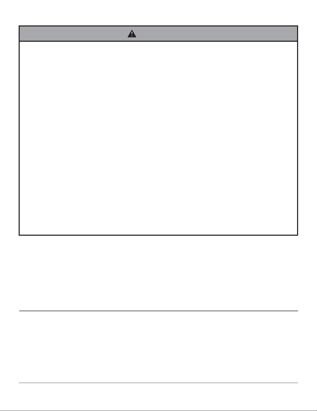
Wall Mount Parts List
Description Qty.
A wall plate 1 201-P1040 201-C4040 201-1040 201-4040 201-1040 201-4040 201-P1040 201-C4040
B tilt-roll assembly 1 201-P1093 201-C4093 201-1093 201-4093 201-1048 201-4048 201-P1048 201-C4048
arm assembly
C
Before you start make sure all parts listed are
included with your product.
Parts List
Description Qty. Part # Part #
D wall support arm axle 1 201-1041 201-1041
E vinyl trim 3 600-1012 600-1012
F M10 x 15 mm screw bolt 8 520-9262 520-9262
G .505 x .75 x .062" nylon washer 1 540-1074 540-1074
H tilt adjustment knob 1 560-0108 560-0108
I carriage bolt 3/8"-16 x 3.25" 1 520-1315 520-1315
J 1.525 x 2 x .062" delrin washer 2 540-1070 540-1070
K #8-32 x .375" socket head screw 1 520-1210 520-1210
L plastic finishing cap 8 590-1123 590-1123
M holding pin 1 580-1166 580-1166
N retainer plug 1 590-1007 590-1007
O 5/16 x 3" wood screw 8 520-1243 520-1243
P .250 x 1 x .068" washer 8 540-1063 540-1063
Q 9/64" allen wrench 1 560-9728 560-9728
R cable management clips 4 590-1166 590-1166
S cable tie 4 590-1168 590-1168
T 36" polyester mesh sleeve 1 600-1015 600-1015
U 6 mm allen wrench 1 560-9716 560-9716
V 10 mm allen wrench 1 - 560-9727
anchor 8 590-0321 590-0321
W
Part # Part #
1 201-P1072
PLA60-UNL
PLA60-UNL-S
PLA60-UNLP
PLA60-UNLP-S
PLA60-UNLP-GB
PLA60-UNLP-GS
201-C4072 201-1072 201-4072
PLA60-UNL
PLA60-UNLPPLA60-UNLP-GSPLA60-UNLP-GB
Part #
PLAV60-UNL
PLAV60-UNL-S
PLAV60-UNLP
PLAV60-UNLP-S
PLAV60-UNLP-GB
PLAV60-UNLP-GS
PLA60-UNL-S
PLA60-UNLP-S
Part # Part # Part #
PLAV60-UNL
PLAV60-UNLP
201-1049 201-4049 201-P1049 201-C4049
A
I
E FD
PLAV60-UNL-S
PLAV60-UNLP-S
B
J
PLAV60-UNLP-GB PLAV60-UNLP-GS
Part # Part #
C
G
H
K
L
MN RQO
P
T
W
S
V
U
3 of 41
ISSUED: 06-05-06 SHEET #: 202-9141-11 (2013-10-01)

Before you begin, make sure all parts shown are included with your product.
Adapter Bracket Parts List
Description Qty Part # Part # Part # Part # Part # Part #
AA adapter bracket 1 201-1110 201-4110 201-1110 201-4110 201-P1110 201-C4110
shallow adapter bracket 2 201-1511 201-4511 201-1514 201-4514 201-P1514 201-C4514
BB
CC allen wrench 1 560-9646 560-9646 560-0072 560-0072 560-0072 560-0072
PLA60-UNL
PLAV60-UNL
AA
PLA60-UNL-S
PLAV60-UNL-S
BB
PLA60-UNLP
PLAV60-UNLP
PLA60-UNLP-S
PLAV60-UNLP-S
CC
PLA60-UNLP-GB
PLAV60-UNLP-GB
PLA60-UNLP-GS
PLAV60-UNLP-GS
M5 x 12 mm (4)
(520-1027)
M5 x 25 mm (4)
M5 x 12mm (4)
(520-1064)
M5 x 25mm (4)
(520-9543)
(520-1122)
Phillips Adapter Bracket Fasteners
M6 x 12 mm (4)
(520-1128)
M6 x 25 mm (4)
(520-1208)
M8 x 12 mm (4)
(520-9571)
.75" spacer (4)
(540-1059)
M8 x 25 mm (4)
(520-1031)
Security Adapter Bracket Fasteners
M6 x 12mm (4)
(520-1050)
M6 x 25mm (4)
(520-1211)
M8 x 12mm (4)
(520-1724)
M8 x 25mm (4)
(520-1101)
.75" spacer (4)
(540-1059)
Multi-washer (4)
(580-1398)
Multi-washer (4)
(580-1398)
4 of 41
ISSUED: 06-05-06 SHEET #: 202-9141-11 (2013-10-01)
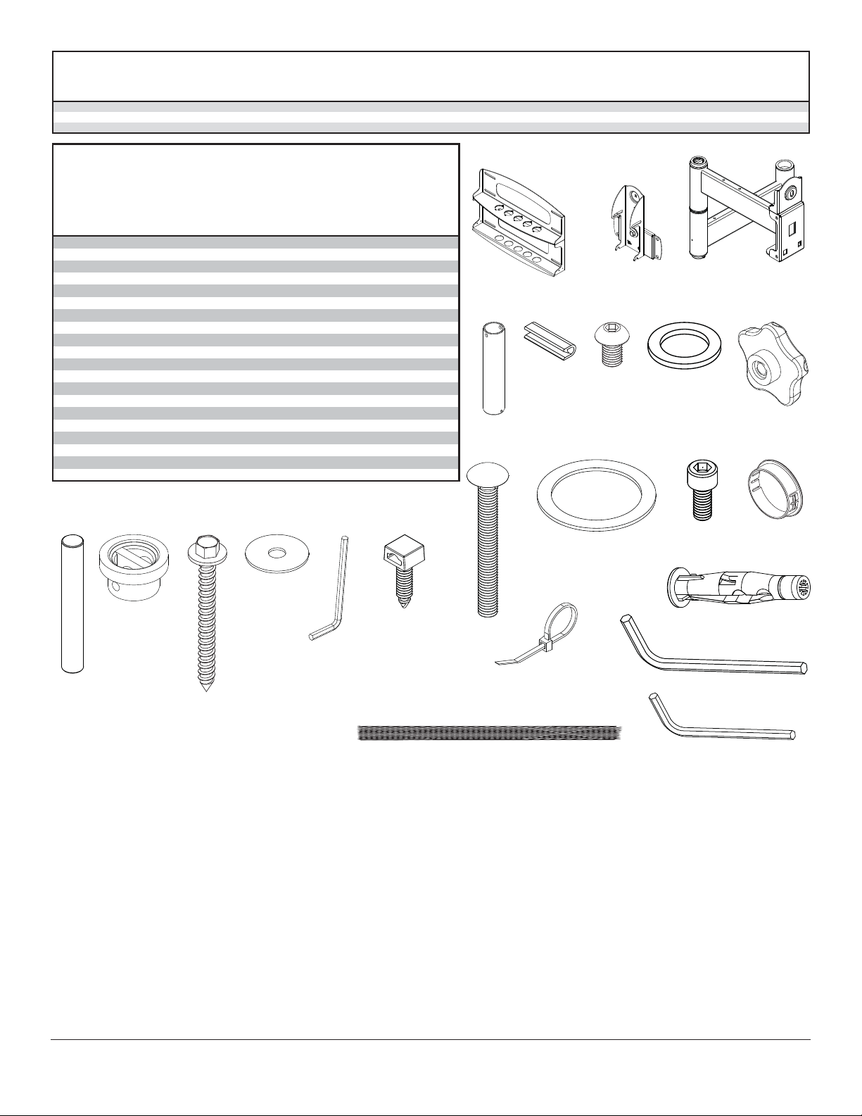
Installation to Wood Stud Wall
WARNING
• Installer must verify that the supporting surface will safely support the combined load of the equipment and all
attached hardware and components.
• Tighten wood screws so that wall plate is fi rmly attached, but do not overtighten. Overtightening can damage the
screws, greatly reducing their holding power.
• Never tighten in excess of 80 in. • lb (9 N.M.).
• Make sure that mounting screws are anchored into the center of the stud. The use of an "edge to edge" stud fi nder
is highly recommended.
• Hardware provided is for attachment of mount through standard thickness drywall or plaster into wood studs. Installers are responsible to provide hardware for other types of mounting situations (not evaluated by UL).
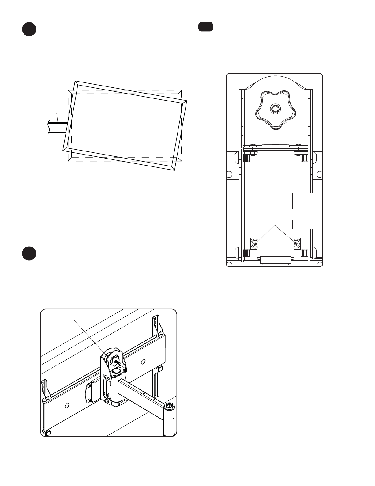
Wall plate (A) can be mounted to two studs that are 16" apart. Use a stud fi nder to locate the edges of the studs.
1
Use of an edge-to-edge stud fi nder is highly recommended. Based on their edges, draw a vertical line down each
stud’s center. Place wall plate on wall as a template. The top mounting slots should be located at your desired
display center. Level plate, and mark the center of the eight mounting holes. Make sure that the mounting holes
are on the stud centerlines. Drill eight 3/16" (5mm) dia. holes 3" (76mm) deep. Make sure that the wall plate is
level, secure it using eight 5/16 x 3" wood screws (O) and washers (P).
Skip to step 2
WARNING
• Never mount this product to metal studs without the
required accessory.
A
P
O
5 of 41
ISSUED: 06-05-06 SHEET #: 202-9141-11 (2013-10-01)

Installation to Solid Concrete or Cinder Block Wall
WARNING
• When installing Peerless wall mounts on cinder block, verify that you have a minimum of 1-3/8" (35mm) of actual
concrete thickness in the hole to be used for the concrete anchors. Do not drill into mortar joints! Be sure to mount
in a solid part of the block, generally 1" (25mm) minimum from the side of the block. Cinder block must meet ASTM
C-90 specifi cations. It is suggested that a standard electric drill on slow setting is used to drill the hole instead of a
hammer drill to avoid breaking out the back of the hole when entering a void or cavity.
• Concrete must be 2000 psi density minimum. Lighter density concrete may not hold concrete anchor.
• Make sure that the supporting surface will safely support the combined load of the equipment and all attached
hardware and components.
Use wall plate (A), making sure that it is level, as
1
a template to mark holes. The top mounting slots
should be located at your desired display center.
Use the masonry bit to drill 3/8" (10mm) dia. holes
to a minimum depth of 3" (76mm). Insert anchors
(W) in holes fl ush with wall as shown (right). Place
wall plate (A) over anchors (W) and secure with
5/16 x 3" wood screws (O) and washers (P).
WARNING
• Tighten screws so that wall plate is fi rmly attached,
but do not overtighten. Overtightening can damage
screws, greatly reducing their holding power.
• Never tighten in excess of 80 in. • lb (9 N.M.).
• Always attach concrete expansion anchors directly
to load-bearing concrete.
• Never attach concrete expansion anchors to
concrete covered with plaster, drywall, or other
fi nishing material. If mounting to concrete surfaces
covered with a fi nishing surface is unavoidable (not
evaluated by UL), the fi nishing surface must be
counterbored as shown below. Be sure concrete
anchors do not pull away from concrete when
tightening screws. If plaster/drywall is thicker than
5/8" (16mm), custom fasteners must be supplied by
installer (not evaluated by UL).
1
concrete
surface
W
Drill holes and insert anchors (W).
O
A
W
2
Place plate (A) over anchors (W) and secure with screws (O).
3
Tighten all fasteners.
W
P
plate
CUTAWAY VIEW
wall
plaster/
dry wall
INCORRECT CORRECT
concrete
wall
plate
plaster/
dry wall
concrete
6 of 41
O
A
ISSUED: 06-05-06 SHEET #: 202-9141-11 (2013-10-01)

WARNING
• If you are uncertain that product is properly installed, call customer care.
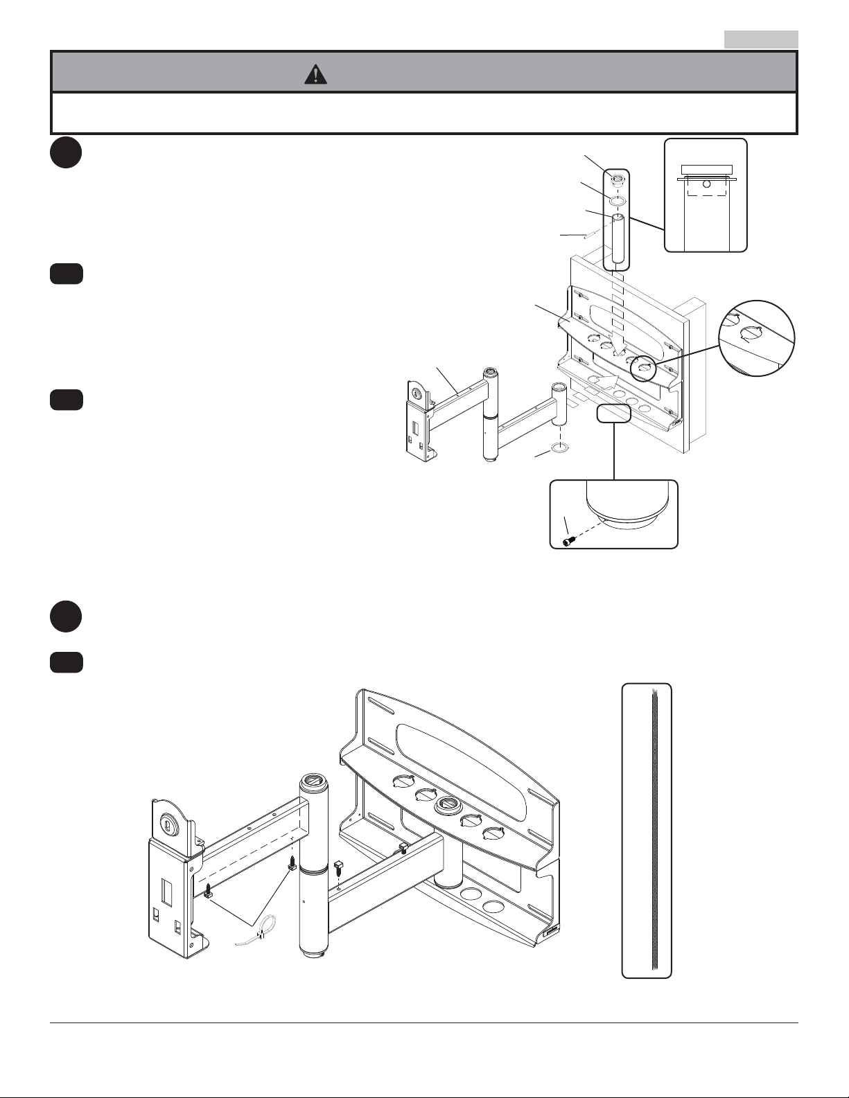
2
2-1
2-2
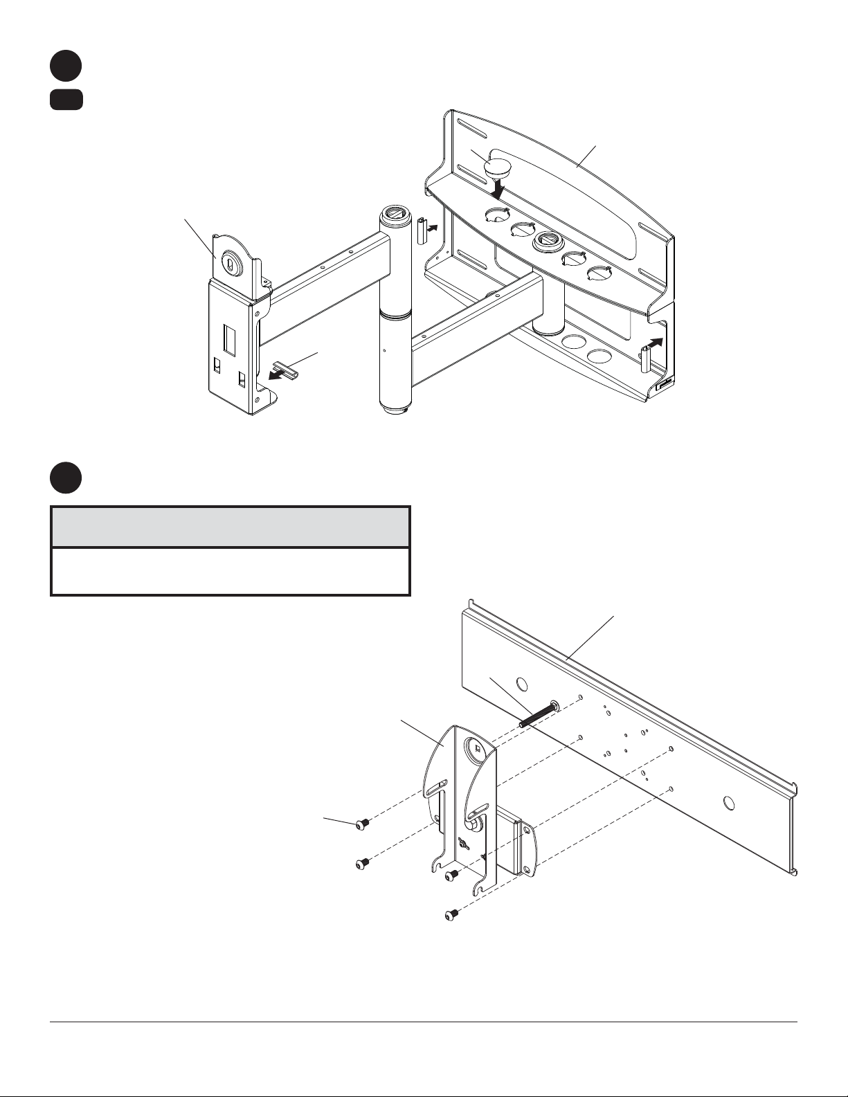
Note: There are fi ve mounting positions. The
center position is shown (right). Slide washer
(J) over wall support arm axle (D). Next, insert
plastic cap (N) into axle. Then, insert holding pin
(M) into axle. See detail 1.
Place arm assembly (C) with washer (J) into wall
plate (A). Insert axle assembly shown in detail
1 through wall plate (A), arm assembly (C), and
washer (J). Lock axle in place by aligning holding pin (M) with notches shown in detail 2.
Insert socket cap screw (K) into hole at bottom
of wall support arm axle (D) as shown in detail 3.
Tighten screw using 9/64" allen wrench (Q).
Note: Fit of axle (D) into wall plate (A) and arm
assembly (C) will be tight. Gently tap into place
with a hammer if necessary.
C
N
J
D
M
DETAIL 1
A
NOTCH
DETAIL 2
J
K
D
3
3-1
DETAIL 3
Snap four cable management clips (R) into top or bottom of arm assembly (C) as shown. Cable ties (S) are used
with clips for cord management.
Slide one mesh sleeve (T) over each cable. Use cable ties (S) to tighten mesh sleeves to cables.
T
R
C
S
7 of 41
ISSUED: 06-05-06 SHEET #: 202-9141-11 (2013-10-01)
4
4-1
Attach two pieces of vinyl trim (E) to wall plate (A). Next, attach one piece of vinyl trim to bottom of swivel box on
arm assembly (C).
Insert one fi nishing cap (L) into each unused hole of wall plate (A).
L
SWIVEL BOX
A
C
E
Insert and tape carriage bolt (I) into top hole of pitch-roll assembly (B). Attach tilt-roll assembly to adapter bracket
5
(AA) with four M10 socket screws (F). Tighten screws using 6mm allen wrench (U).
CAUTION
• Do not overtighten screws! Overtightening may
hinder roll option.
F
AA
I
B
8 of 41
ISSUED: 06-05-06 SHEET #: 202-9141-11 (2013-10-01)
WARNING
• Use an assistant or mechanical lifting equipment to safely lift and position the plasma TV.
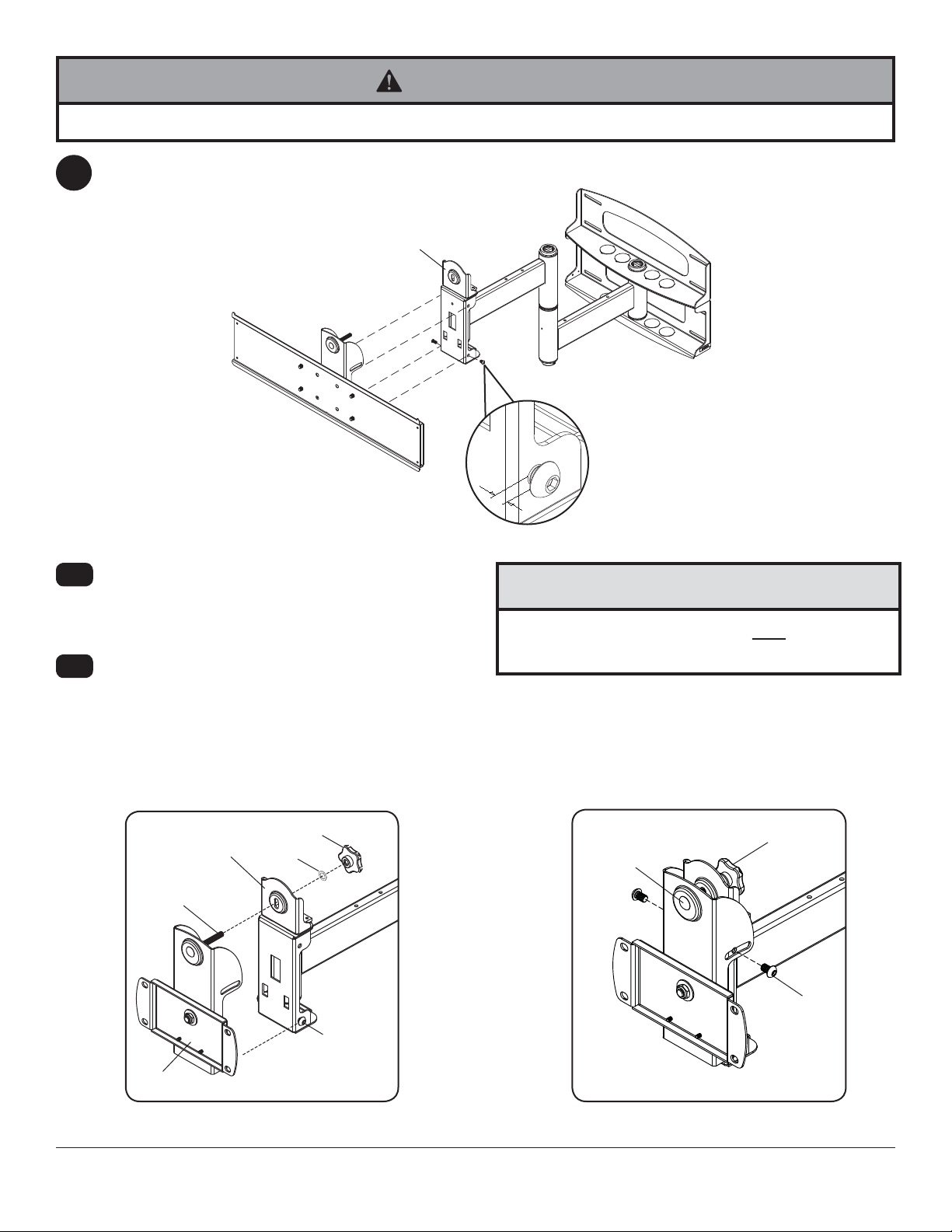
Insert two M10 screws (F) into swivel box on arm assembly (C) as shown. Leave approx. .25" of exposed thread.
6
6-1
6-2
SWIVEL BOX
Hook tilt-roll assembly (B) onto M10 screws (F).
Insert carriage bolt (I) into slot of swivel box as
shown in fi gure 6.1. Install nylon washer (G) and tilt
adjustment knob (H).
Install remaining two M10 screws (F) as shown in
fi gure 6.2. HAND TIGHTEN all four M10 screws to
allow for tilt adjustment. Remove tape from carriage
bolt (I). For tilt adjustment, push back on the top of
plasma to relieve pressure on knob. Adjust tilt to
desired position and tighten tilt adjustment knob (H),
then securely tighten all four M10 screws (F) using
6mm allen wrench (U).
C
F
.25"
CAUTION
• After tilt is adjusted, all fasteners must be tightened.
Failure to do so will result in damage to the mount.
SWIVEL BOX
H
G
H
I
I
F
F
B
Adapter bracket not shown for clarity. Adapter bracket not shown for clarity.
fi g. 6.1 fi g. 6.2
9 of 41
ISSUED: 06-05-06 SHEET #: 202-9141-11 (2013-10-01)
Installing Adapter Brackets
WARNING
• Tighten screws so adapter brackets are fi rmly attached. Do not tighten with excessive force. Overtightening can
cause stress damage to screws, greatly reducing their holding power and possibly causing screw heads to become
detached. Tighten to 40 in. • lb (4.5 N.M.) maximum torque.
• If screws don't get three complete turns in the display inserts or if screws bottom out and bracket is still not tightly
secured, damage may occur to display or product may fail.
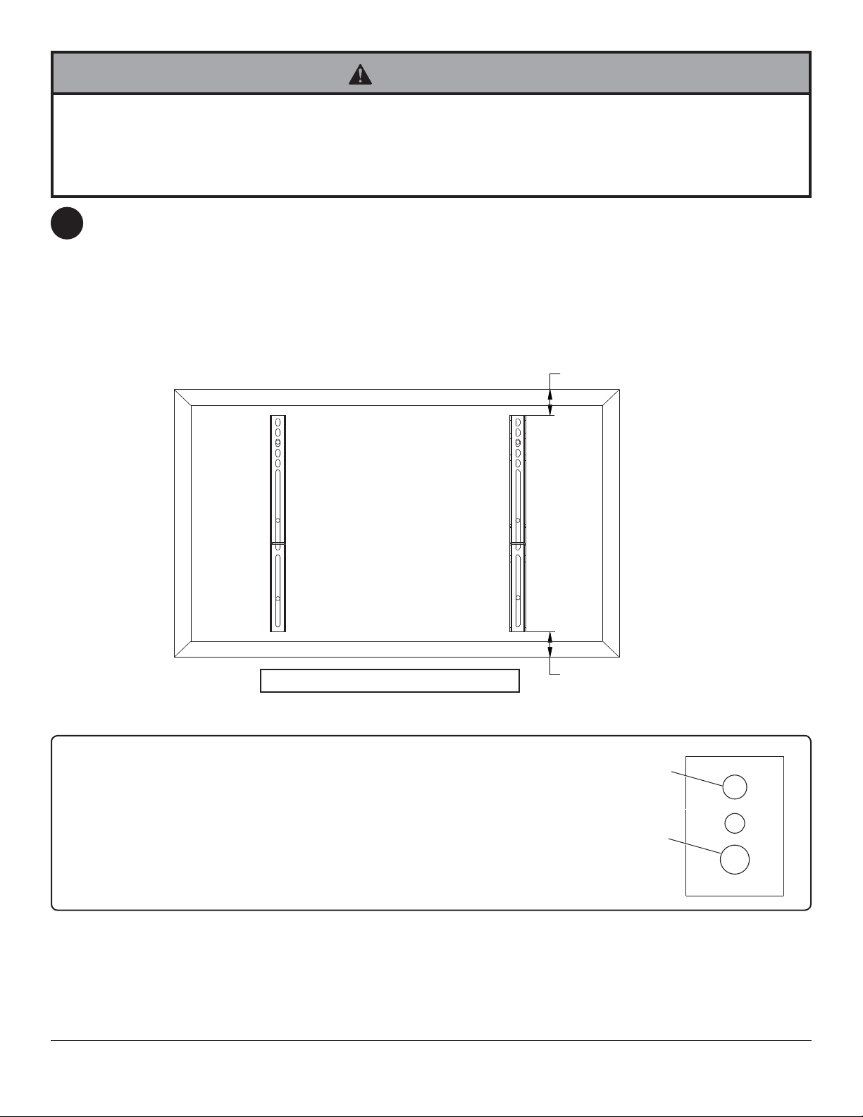
To prevent scratching the display, set a cloth on a fl at, level surface that will support the weight of the display.
7
Place display face side down. If display has knobs on the back, remove them to allow the adapter brackets to be
attached. Place adapter brackets (BB) on back of display, align to holes, and center on back of display as shown
below. Attach the adapter brackets to the back of the display using the appropriate combination of screws, multiwashers, and spacers as shown in fi gure 7.1 and fi gure 7.2.
NOTE: Top and bottom holes on display must always be used.
Verify that all holes are properly aligned, and then tighten screws using a phillips screwdriver.
NOTE: If using security screws, tighten using security allen wrench (CC).
X
BB
Note: "X" dimensions should be equal.
Notes:
• The number of fasteners used will vary,
depending upon the type of display.
• Multi-washers and spacers may not be used,
depending upon the type of display.
• Use the corresponding hole in the multiwasher that matches your screw size as shown.
CENTER BRACKETS
VERTICALLY ON BACK
OF DISPLAY
X
MULTI-WASHER
MEDIUM HOLE FOR M5 SCREWS
LARGE HOLE FOR M6 SCREWS
NOTE: For fl at back displays proceed to step 7-1. For bump-out or recessed back display skip to step 7-2
10 of 41
ISSUED: 06-05-06 SHEET #: 202-9141-11 (2013-10-01)

For Flat Back Display
Begin with the shortest length screw, hand thread through multi-washer and adapter bracket into display as
7-1
shown below. Screw must make at least three full turns into the mounting hole and fi t snug into place. Do not
over tighten. If screw cannot make three full turns into the display, select a longer length screw from the baffl ed
fastener pack. Repeat for remaining mounting holes, level brackets and tighten screws.
NOTE: Spacers may not be used, depending upon the type of display.
If you have any questions, please call Peerless customer care at 1-800-865-2112.
fi g. 7.1
DISPLAY
MULTI-WASHER
SCREW
ADAPTER
BRACKET
(BB)
For Bump-out or Recessed Back Display
Begin with longer length screw, hand thread through multi-washer, adapter bracket and spacer in that order into
7-2
display as shown below. Screw must make at least three full turns into the mounting hole and fi t snug into place.
Do not over tighten. If screw cannot make three full turns into the display, select a longer length screw from the
baffl ed fastener pack. Repeat for remaining mounting holes, level brackets and tighten screws.
DISPLAY
SPACER
If you have any questions, please call Peerless customer care at 1-800-865-2112.
fi g. 7.2
MULTI-WASHER
SCREW
ADAPTER
BRACKET
(BB)
11 of 41
ISSUED: 06-05-06 SHEET #: 202-9141-11 (2013-10-01)
Mounting and Removing Flat Panel Display
WARNING
• Always use an assistant or mechanical lifting equipment to safely lift and position the plasma television.
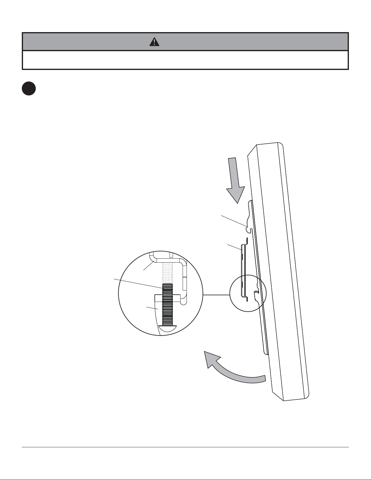
Refer to mount instruction sheet for attachment of adapter bracket to mount.
Hook adapter brackets (BB) onto adapter bracket (AA), then slowly swing display in as shown. Turn screws
8
clockwise at least six times to prevent display from being removed as shown in detail 4. Tighten using allen
wrench (CC).
Display can be adjusted horizontally if desired.
Note: To lock the display down, tighten screws to adapter bracket as shown in detail 4.
To remove display from mount, loosen screws, swing display away from mount, and lift display off of mount.
SAFETY/SECURITY
SCREWS
BB
AA
AA
BB
DETAIL 4
12 of 41
ISSUED: 06-05-06 SHEET #: 202-9141-11 (2013-10-01)
Depending on the specifi c size & weight of the plas-
9
ma, articulating swing arm may be angled at different
positions, causing plasma to appear to lean sideways
at different articulating positions. Tilt-roll assembly (B)
allows plasma to be manually adjusted, so plasma
can be horizontal at all positions. To adjust, gently
rotate plasma by hand to desired position.
ARTICULATING
ARM
PLASMA
If it is too diffi cult to adjust roll of plasma, loosen
9-1
screws shown in fi gure 9.1 using a phillips screw-
driver.
IMPORTANT! Do not loosen or tighten screws
more than 1/8 turn.
10
FOR PLAV60 ONLY:
Position of display may be adjusted vertically up to .79" in
each direction by doing the following:
• To lower display, turn socket screw shown in fi gure 10.1
clockwise with 10mm allen wrench (V).
• To raise display, turn socket screw shown in fi gure 10.1
counterclockwise with 10mm allen wrench (V).
SOCKET
SCREW
ROLL
ADJUSTMENT
SCREWS
fi g. 9.1
fi g. 10.1
13 of 41
All other brand and product names are trademarks or registered trademarks of their respective owners.
ISSUED: 06-05-06 SHEET #: 202-9141-11 (2013-10-01)
© 2013, Peerless Industries, Inc. All rights reserved.

Instalación y ensamblaje:
Brazo articulador de giro universal para pantallas de 37" - 65"
Modelos
PLA60-UNL, PLA60-UNL-S,
PLA60-UNLP, PLA60-UNLP-S,
PLAV60-UNL, PLAV60-UNL-S,
PLAV60-UNLP, PLAV60-UNLP-S,
PLA60-UNLP-GB, PLA60-UNLP-GS,
PLAV60-UNLP-GB, PLAV60-UNLP-GS
Capacidad de carga máxima de UL:
175 lb (79 kg)
2300 White Oak Circle • Aurora, Il 60502 • (800) 865-2112 • Fax: (800) 359-6500 • www.peerless-av.com
PUBLICADO: 06-05-06 HOJA #:202-9141-10 06-14-12

Español
Nota:
Lea la hoja de instrucciones completa antes de comenzar la instalación y el ensamblaje.
ADVERTENCIA
• No comience a instalar su producto de Peerless hasta haber leído y entendido las instrucciones y las advertencias
contenidas en la Hoja de Instalación. Si tiene alguna pregunta acerca de cualquiera de las instrucciones o las
advertencias, por favor, llame a Servicio al Cliente de Peerless al 1-800-865-2112 si está en EE. UU. Si es un cliente
internacional, por favor, comuníquese con su distribuidor local.
• Este producto sólo debe ser instalado por una persona que tenga una buena aptitud mecánica, que tenga
experiencia en construcción básica de edifi cios y que entienda estas instrucciones en su totalidad.
• Asegúrese de que la superfi cie de apoyo sostendrá, con seguridad, la carga combinada del equipo y todos los
fi jadores y componentes.
• Nunca sobrepase la capacidad máxima de soportar carga aceptada por Underwriters Laboratories. Vea la página 14.
• Si va a instalar el producto en una pared con montantes de madera, asegúrese de que los tornillos de montaje estén
anclados en el centro de los montantes. Se recomienda utilizar un localizador de montantes de "borde a borde".
• Siempre cuente con la ayuda de un asistente o utilice un equipo mecánico de izar para levantar y colocar el equipo
con más seguridad.
• Apriete los tornillos con fi rmeza, pero no en exceso. Apretarlos en exceso puede dañar los artículos y puede
disminuir signifi cativamente su fuerza de fi jación.
• Este producto está diseñado para uso en interiores solamente. Utilizar este producto en exteriores podría causar
fallas del producto y lesiones a individuos.
• Este producto fue diseñado para ser instalado en paredes con la siguiente construcción solamente:
CONSTRUCCIÓN DE LA PARED ACCESORIOS NECESARIOS
• Montante de madera Incluido
• Viga de madera Incluido
• Concreto macizo Incluido
• Bloque de hormigón de escorias Incluido
• Montante de metal No lo instale excepto con el juego de accesorios de Peerless para
montantes de metal (no evaluados por UL)
• Ladrillo Comuníquese con un profesional califi cado (no evaluados por UL)
• ¿Otra superfi cie o no está seguro? Comuníquese con un profesional califi cado
Herramientas necesarias para el ensamblaje
• localizador de montantes (se recomienda uno de “borde a borde”)
• taladro
• broca de 3/16" (5mm) para montantes de madera
• broca de 3/8" (10mm) para taladro de albaρilerνa para concreto
• llave de copa 7/16" con extensión (se recomienda)
• nivel
• destornillador phillips
Accesorios
• Placa de pared externa (WSP716, WSP716-S,
WSP724, WSP724-S)
(Montante de metal no evaluado por UL).
Tabla de contenido
Lista de piezas............................................................................................................................................................... 16, 17
Instalación en una pared con montantes de madera dobles ............................................................................................... 18
Instalación en una pared de concreto macizo o de bloques de hormigón de escorias ....................................................... 19
15 de 41
PUBLICADO: 06-05-06 HOJA #:202-9141-11 (2013-10-01)

Español
p
E FD
PLAV60-UNL-S
PLAV60-UNLP-SPLA60-UNLP-GB PLA60-UNLP-GS PLA60-UNL
B
J
PLAV60-UNLP-GB PLAV60-UNLP-GS
C
G
K
Lista de piezas
Descripción Cant. Nº de pieza Nº de pieza Nº de pieza
A placa de pared 1 201-P1040 201-C4040 201-1040 201-4040 201-1040 201-4040 201-P1040 201-C4040
B armazón de inclinación y giro 1 201-P1093 201-C4093 201-1093 201-4093 201-1048 201-4048 201-P1048 201-C4048
armazón del brazo
C
Antes de comenzar, asegúrese de que su
producto incluye todas las piezas indicadas
en la lista.
1 201-P1072
Lista de piezas
Descripción Cant. Nº de pieza Nº de pieza
D eje del brazo de soporte de pared 1 201-1041 201-1041
E ribete de vinilo 3 600-1012 600-1012
F tornillo de rosca M10 x 15 mm 8 520-9262 520-9262
G arandela de nilón .505 x .062" 1 540-1074 540-1074
H perilla ajuste de la inclinación 1 560-0108 560-0108
I perno cabeza 3/8"-16 x 3.25" 1 520-1315 520-1315
J arandela delrin de 1.525 x .062" 2 540-1070 540-1070
K tornillo hueca 8 x -32 x 0.375" 1 520-1210 520-1210
L cubierta plástica de acabado 8 590-1123 590-1123
M pasador de sujeción 1 580-1166 580-1166
N tapón retenedor 1 590-1007 590-1007
O tornillo de madera 5/16 x 3" 8 520-1243 520-1243
P arandela de 250 x 1 x .068" 8 540-1063 540-1063
Q llave allen de 9/64 1 560-9728 560-9728
R clips de sujeción de cables 4 590-1166 590-1166
S sujetacables 4 590-1168 590-1168
T funda de malla de poliéster 36" 1 600-1015 600-1015
U llave allen de 6 mm 1 560-9716 560-9716
V llave allen de 10 mm 1 - 560-9727
anclaje para concreto 8 590-0321 590-0321
W
201-C4072 201-1072 201-4072
PLA60-UNL
PLA60-UNL-S
PLA60-UNLP
PLA60-UNLP-S
PLA60-UNLP-GB
PLAV60-UNL
PLAV60-UNL-S
PLAV60-UNLP
PLAV60-UNLP-S
PLAV60-UNLP-GB
PLAV60-UNLP-GS
PLA60-UNL-S
PLA60-UNLP-S
Nº de pieza
PLAV60-UNL
PLAV60-UNLP
Nº de pieza Nº de pieza Nº de pieza Nº de pieza
201-1049 201-4049 201-P1049 201-C4049
A
I
H
L
MN RQO
P S
T
W
V
U
16 de 41
PUBLICADO: 06-05-06 HOJA #:202-9141-11 (2013-10-01)

Antes de comenzar, asegúrese de que su producto contiene todas las partes que se muestran.
Español
Lista de piezas
Descripción Cant. Nº de pieza Nº de pieza Nº de pieza Nº de pieza Nº de pieza Nº de pieza
AA soporte adaptador 1 201-1110 201-4110 201-1110 201-4110 201-P1110 201-C4110
soporte adaptador de poca profundidad 2 201-1511 201-4511 201-1514 201-4514 201-P1514 201-C4514
BB
CC llave allen 1 560-9646 560-9646 560-0072 560-0072 560-0072 560-0072
PLA60-UNL
PLAV60-UNL
AA
PLA60-UNL-S
PLAV60-UNL-S
BB
PLA60-UNLP
PLAV60-UNLP
PLA60-UNLP-S
PLAV60-UNLP-S
CC
PLA60-UNLP-GB
PLAV60-UNLP-GB
PLA60-UNLP-GS
PLAV60-UNLP-GS
Fijaciones Phillips para los soportes adaptadores
M5 x 12 mm (4)
(520-1027)
M5 x 25 mm (4)
(520-9543)
M6 x 12 mm (4)
(520-1128)
M6 x 25 mm (4)
(520-1208)
M8 x 12 mm (4)
(520-9571)
.75" espaciador (4)
(540-1059)
M8 x 25 mm (4)
(520-1031)
Fijaciones de seguridad para los soportes adaptadores
M5 x 12mm (4)
(520-1064)
M5 x 25mm (4)
(520-1122)
M6 x 12mm (4)
(520-1050)
M6 x 25mm (4)
(520-1211)
M8 x 12mm (4)
(520-1724)
M8 x 25mm (4)
(520-1101)
.75" espaciador (4)
(540-1059)
arandela múltiple (4)
(580-1398)
arandela múltiple (4)
(580-1398)
17 de 41
PUBLICADO: 06-05-06 HOJA #:202-9141-11 (2013-10-01)

Español
Instalación en una pared con montantes de madera
ADVERTENCIA
• El instalador debe verifi car que la superfi cie de apoyo sea capaz de soportar fi rmemente la carga combinada del
equipo y todos los herrajes y componentes.
• Apriete los tornillos para madera de tal modo que la placa de apoyo quede fi rmemente sujeta, pero no apriete en
exceso. El apriete excesivo puede dañar los tornillos, reduciendo enormemente su fuerza de fi jación.
• Nunca apriete más de 80 pulg-lb (9 N•m).
• Asegúrese de que los tornillos de montaje queden bien fi jos en el centro del montante. Se recomienda usar un
localizador de montantes de "borde a borde".
• Los herrajes suministrados son para fi jar el soporte a través de tabique de yeso-cartón o yeso de espesor estándar
a los montantes de madera. Los instaladores son responsables de suministrar los herrajes para otros tipos de
situaciones de montaje (no evaluados por UL).
La placa de pared (A) se puede instalar en dos montantes que tengan una separaciσn de 16". Utilice un
1
localizador de montantes para ubicar los bordes de los montantes. Se recomienda utilizar un localizador de
montantes de “borde a borde”. Tomando los bordes como punto de referencia, trace una lνnea vertical por el
centro de cada montante. Coloque la placa de pared contra la pared para utilizarla como plantilla. Las ranuras
superiores de montaje deben estar ubicadas donde quiere que el centro de la pantalla. Nivele la placa y marque
el centro de los ocho agujeros de montaje. Asegϊrese de que los agujeros de montaje estιn sobre las lνneas
que trazσ por el centro de los montantes. Taladre ocho agujeros de 3/16" (5mm) de diámetro y 3" (76mm) de
profundidad. Asegϊrese de que la placa estι nivelada, fνjela usando ocho tornillos para madera de 5/16 x 3" (O) y
las arandelas (P).
Proceda al paso 2
ADVERTENCIA
• Nunca instale este producto con montantes de metal
sin el accesorio necesario.
A
P
O
18 de 41
PUBLICADO: 06-05-06 HOJA #:202-9141-11 (2013-10-01)

Instalación en una Pared de Concreto Macizo o de Bloques de
Español
Hormigón de Escorias
ADVERTENCIA
• Cuando instale soportes de pared Peerless en bloques de hormigón de escorias, verifi que que tengan un mínimo de 1-3/8"
(35mm) de superfi cie efectiva de concreto en el agujero que va a utilizar para los anclajes de concreto. ¡No perfore en las juntas
de mortero! Asegúrese de instalar el soporte en una parte sólida del bloque, generalmente a un mínimo de 1" (25mm) del costado
del bloque. El bloque de hormigón de escorias debe ser de conformidad con las especifi caciones C-90 de ASTM. Se sugiere
taladrar el agujero con un taladro eléctrico normal en velocidad lenta en vez de un taladro percutor para evitar romper la parte
trasera del agujero al entrar en un espacio o cavidad.
• El concreto debe tener una densidad mínima de 2000 psi. Un concreto menos denso podría no ser capaz de sujetar el anclaje
para concreto.
• El instalador debe verifi car que la superfi cie de apoyo sea capaz de soportar fi rmemente la carga combinada del equipo y todos
los herrajes y componentes.
Utilice la placa de pared (A), asegurándose de
1
que esté nivelada, como plantilla para marcar
los agujeros. Las ranuras superiores de montaje
deben estar ubicadas donde quiere que el centro
de la pantalla. Utilice el pedacito de la albañilería
para perforar 3/8" (10mm) diámetro. agujeros a
una profundidad mínima de 3" (76mm). Inserte los
anclajes (W) en los agujeros a ras con la pared,
como se muestra (a la derecha). Coloque la placa
de pared (A) sobre los anclajes (W) y fi jela con
los tornillos para madera de 5/16 x 3" (O) y las
arandelas (P).
ADVERTENCIA
• Apriete los tornillos de tal modo que la placa de apoyo
quede fi rmemente sujeta, pero no los apriete en exceso.
El apriete excesivo puede dañar los tornillos, reduciendo
enormemente su fuerza de fi jación.
• Nunca apriete más de 80 pulg-lb (9 N•m).
• Siempre fi je los anclajes de expansión directamente al
concreto que soporta carga.
• Nunca fi je los anclajes de expansión a una pared de
concreto recubierta con yeso, tabiques de yeso-cartón u
otro material de acabado. Si el montaje a superfi cies de
concreto recubiertas con una superfi cie de acabado es
inevitable (no evaluadas por UL), será necesario escariar el
acabado, como se muestra más abajo. Asegúrese de que
los anclajes de concreto no se alejen del concreto al apretar
los tornillos. Si el grosor de la pared de yeso/tabique de
yeso-cartón es mayor que 5/8" (16mm), el instalador deberá
suministrar fi jaciones especiales (no evaluadas por UL).
1
Perfore los agujeros y después inserte los anclajes (W).
2
A
O
Coloque la placa (A) sobre los anclajes (W) y fíjela con
los tornillos (O).
3
Apriete todas las fi jaciones.
W
P
superfi cie de
concreto
W
W
placa
de
pared
VISTA EN CORTE
INCORRECTO
concreto
yeso / tabique de yeso-cartón
placa
pared
de
CORRECTO
concreto
19 de 41
O
A
PUBLICADO: 06-05-06 HOJA #:202-9141-11 (2013-10-01)

ADVERTENCIA
• Si no está seguro de que el producto esté bien instalado, llame a Servicio al Cliente.
Nota: Hay cinco posiciones de instalación.
2
Se muestra la posición central (derecha).
Deslice la arandela (J) sobre el eje del brazo del
soporte de pared (D). Luego inserte la cubierta
plástica de acabado (N) en el eje. Luego inserte
2-1
2-2
el pasador de sujeción (M) en el eje. Vea el
detalle 1.
Coloque el armazón del brazo (C) con la
arandela (J) en la placa de pared (A). Inserte el
armazón del eje que se muestra en el detalle 1 a
través de la placa de pared (A) y la arandela (J).
Fije el eje en su lugar alineando el pasador de
sujeción (M) con las muescas, que se muestran
en el detalle 2.
Inserte el tornillo de cabeza hueca (K) en el
agujero de la parte interior del eje del brazo del
soporte de pared (D), como se muestra en el
detalle 3. Apriete el tornillo usando una llave
allen de 9/64" (Q).
Nota: El eje (D) quedará apretado en la placa
de pared (A) y en el armazón del brazo (C).
Déle golpecitos suaves con un martillo para
llevarlo a su lugar, de ser necesario.
C
M
A
J
K
Español
N
J
D
DETALLE 1
Muesca
DETALLE 2
D
3
3-1
DETALLE 3
Inserte, a presión, cuatro clips de sujeción de cables (R) en la parte superior o en la parte inferior del armazón del
brazo (C), como se muestra. Los sujetacables (S) se usan con los clips para recoger los cordones.
Deslice una funda de malla (T) sobre cada cable. Use los sujetacables (S) para apretar la funda de malla que
cubre los cables.
T
R
C
S
20 de 41
PUBLICADO: 06-05-06 HOJA #:202-9141-11 (2013-10-01)

4
4-1
Español
Adhiera dos pedazos del ribete de vinilo (E) a la placa de pared (A). Luego adhiera un pedazo del ribete de vinilo
a la parte inferior de la caja giratoria del armazón del brazo (C).
Inserte una capa plástica de acabado (L) en cada agujero que no haya utilizado de la placa de pared (A).
L
CAJA GIRATORIA
A
C
E
Inserte y adhiera, con un pedazo de cinta adhesiva, el perno de cabeza redonda (I) al armazón de inclinación y
5
giro (B). Fije el armazón de inclinación y giro en el soporte adaptador (AA) con cuatro tornillos de cabeza hueca
M10 (F). Apriete los tornillos usando una llave allen de 6mm (U).
ATENCION
• ¡No apriete los tornillos en exceso! Apretarlos en
exceso puede limitar la opción de giro.
F
AA
I
B
21 de 41
PUBLICADO: 06-05-06 HOJA #:202-9141-11 (2013-10-01)

Español
ADVERTENCIA
• Cuente con un asistente o con un equipo mecánico de izar para levantar y colocar el televisor de plasma con más
seguridad.
Inserte dos tornillos M10 (F) en la caja giratoria del armazón del brazo (C), como se muestra. Deje
6
aproximadamente .25" de la rosca expuesto.
6-1
6-2
Enganche el armazón de inclinación y giro (B) en
los tornillos M10 (F). Inserte el perno de cabeza
redonda (I) en la ranura de la caja giratoria,
como se muestra en la ilustración 6.1. Instale la
arandela de nilón (G) y la perilla de ajuste de la
inclinación (H).
Instale los dos tornillos M10 (F) que quedan,
como se muestra en la ilustración 6.2. APRIETE A
MANO los cuatro tornillos M10 para poder ajustar
la inclinación. Quite la cinta adhesiva del perno
de cabeza redonda (I). Para ajustar la inclinación,
empuje la parte superior de la pantalla de plasma
para disminuir la presión sobre la perilla. Ajuste
la inclinación a la posición deseada y apriete
la perilla de ajuste de la inclinación (H) y luego
apriete fi rmemente los cuatro tornillos M10 (F)
usando una llave allen de 6mm (U).
CAJA GIRATORIA
C
F
.25"
ATENCION
• Después de ajustar la inclinación, tiene que apretar
todas las fi jaciones. Si no lo hace, el resultado será
que le causará daño al soporte.
CAJA GIRATORIA
H
G
I
F
B
El soporte adaptador no se muestra
para propósitos aclaratorios.
fi g. 6.1 fi g. 6.2
22 de 41
H
I
F
El soporte adaptador no se muestra
para propósitos aclaratorios.
PUBLICADO: 06-05-06 HOJA #:202-9141-11 (2013-10-01)

Instalación de los soportes adaptadores
Español
ADVERTENCIA
• Apriete los tornillos de manera que los soportes adaptadores se fi jen con fi rmeza. No los apriete con fuerza
excesiva. Apretar los tornillos en exceso puede causarles daño por forzarlos, y puede disminuir signifi cativamente
su fuerza de fi jación y podría causar el desprendimiento de las cabezas de los tornillos. Apriete los tornillos a un
máximo de 40 pulg-lb (4.5 N•m) de par torsor.
• Si no se les da tres vueltas completas a los tornillos en los insertos de la pantalla o si los tornillos topan fondo y la
placa todavía no está fi rme, se podría dañar la pantalla o el producto podría no funcionar bien.
Para no rayar la pantalla, coloque un trapo sobre una superfi cie plana y nivelada que sostenga el peso de la
7
pantalla. Coloque la pantalla boca abajo. Si la pantalla tiene perillas en la parte trasera, quíteselas para poder
fi jar los soportes adaptadores. Coloque los soportes adaptadores (BB) en la parte trasera de la pantalla, alinéelos
con los agujeros y centralícelos en la parte trasera de la pantalla, como se muestra abajo. Fije los soportes
adaptadores en la parte trasera de la pantalla utilizando la combinación adecuada de tornillos, arandelas múltiples
y espaciadores, como se muestra en la fi gura 7.1 o en la fi gura 7.2.
NOTA: Siempre se tienen que usar los agujeros superiores y los inferiores.
Verifi que que todos los agujeros estén debidamente alineados y luego apriete los tornillos usando un destornillador
phillips.
NOTA: Si va a utilizar tornillos de seguridad, apriételos usando una llave allen de seguridad (CC).
X
BB
NOTA: Las dimensiones "X" deben ser iguales.
Notas:
• El número de fi jaciones que se utilizará variará,
dependiendo del tipo de pantalla.
• Es posible que no necesite las arandelas
múltiples y los espaciadores, dependiendo del
tipo de pantalla.
• Utilice el agujero correspondiente de la
arandela múltiple que sea del mismo tamaño
del tornillo, como se muestra.
CENTRALICE
LOS SOPORTES
VERTICALMENTE EN LA
PARTE TRASERA DE LA
PANTALLA
X
ARANDELA MÚLTIPLE
AGUJERO MEDIANO PARA
TORNILLOS M5
AGUJERO GRANDE PARA
TORNILLOS M6
NOTA: En el caso de los televisores que tienen la parte posterior plana, pase al paso 7-1. En el caso de los televisores
que tienen la parte posterior abultada o empotrada, pase al paso 7-2.
23 de 41
PUBLICADO: 06-05-06 HOJA #:202-9141-11 (2013-10-01)

Instalación de un televisor que tiene la parte posterior plana
Comience con uno de los tornillos más cortos, enrósquelo, con la mano, a través de la arandela múltiple y el
7-1
soporte adaptador a la parte posterior de la pantalla, como se muestra abajo. El tornillo debe dar, por lo menos,
tres vueltas completas dentro del agujero de instalación y debe quedar ajustado en su lugar. No apriete los
tornillos en exceso. Si el tornillo no puede dar tres vueltas completas al entrar en la parte posterior de la pantalla,
seleccione un tornillo más largo de los sujetadores identifi cados y clasifi cados en las divisiones del empaque
plástico. Siga el mismo procedimiento con los agujeros de instalación restantes, nivele los soportes y apriete los
tornillos.
NOTA: Es posible que no necesite usar los espaciadores, dependiendo del tipo de pantalla.
PANTALLA
ARANDELA
MÚLTIPLE
SOPORTE
ADAPTADOR
(BB)
Español
fi g. 7.1
TORNILLO
Si tiene alguna pregunta, por favor, llame a servicio al cliente de Peerless al 1-800-865-2112.
Instalación de un televisor que tiene la parte posterior abultada o empotrada
Comience con uno de los tornillos más largos, enrósquelo, con la mano, a través de la arandela múltiple, el
7-2
soporte adaptador y el espaciador, en ese orden, a la parte posterior de la pantalla, como se muestra abajo. El
tornillo debe dar, por lo menos, tres vueltas completas dentro del agujero de instalación y debe quedar ajustado
en su lugar. No apriete los tornillos en exceso. Si el tornillo no puede dar tres vueltas completas al entrar en la
parte posterior de la pantalla, seleccione un tornillo más largo de los sujetadores identifi cados y clasifi cados
en las divisiones del empaque plástico. Siga el mismo procedimiento con los agujeros de instalación restantes,
nivele los soportes y apriete los tornillos.
fi g. 7.2
PANTALLA
ARANDELA
ESPACIADOR
MÚLTIPLE
TORNILLO
SOPORTE
ADAPTADOR
(BB)
Si tiene alguna pregunta, por favor, llame a servicio al cliente de Peerless al 1-800-865-2112.
24 de 41
PUBLICADO: 06-05-06 HOJA #:202-9141-11 (2013-10-01)

Instalación y desinstalación de la pantalla plana
ADVERTENCIA
• Siempre cuente con un asistente o con un equipo mecánico de izar para levantar y colocar el televisor de plasma
con más seguridad.
Refi érase a la hoja de instrucciones del soporte para saber cómo fi jar el soporte adaptador.
8
Enganche los soportes adaptadores (BB) a la placa de pared (AA) y luego gire la pantalla lentamente hacia
dentro, como se muestra. Déles, por lo menos seis vueltas a los tornillos en el sentido del movimiento de las
manecillas del reloj para evitar que se pueda quitar la pantalla, como se muestra en el detalle 4. Apriete los
tornillos usando una llave allen (CC).
La pantalla se puede ajustar horizontalmente si lo desea.
Nota: Para trabar la pantalla, apriete los tornillos de seguridad al soporte adaptador, como se muestra en el
detalle 4.
Para quitar la pantalla del soporte, afl oje los tornillos, gire la pantalla retirándola del soporte y levántela para
sacarla del soporte.
Español
TORNILLOS
BB
AA
AA
BB
DETALLE 4
25 de 41
PUBLICADO: 06-05-06 HOJA #:202-9141-11 (2013-10-01)

Dependiendo del modelo y el peso específi cos
9
de la pantalla de plasma, el ángulo del brazo
articulador de giro se puede ajustar a diferentes
posiciones, lo cual puede causar que parezca que
la pantalla de plasma se inclina hacia uno de los
lados en las diferentes posiciones.
de inclinación y giro (B) le permite ajustar la
pantalla de plasma manualmente, de manera que
la pantalla se pueda mantener horizontal en todas
las posiciones. Para ajustarla, gire la pantalla de
plasma suavemente hasta la posición deseada.
BRAS
ARTICULANT
PLASMA
El armazón
9-1
Español
Si se hace difícil girar la pantalla de plasma,
afl oje los tornillos que se muestran en la
ilustración 9.1 usando un destornillador phillips.
¡IMPORTANTE! No afl oje ni apriete los tornillos
más de 1/8 de vuelta.
10
TORNILLOS
GIRO
AJUSTE
TORNILLOS
SÓLO PARA EL MODELO PLAV60:
La posición de la pantalla se puede ajustar verticalmente
hasta .79" en cada dirección haciendo lo siguiente:
• Para bajar la pantalla, gire el tornillo de cabeza hueca
que se muestra en la ilustración 10.1 en el sentido del
movimiento de las manecillas del reloj con la llave allen
de 10mm (V).
• Para subir la pantalla, gire el tornillo de cabeza hueca
que se muestra en la ilustración 10.1 en el sentido
opuesto al movimiento de las manecillas del reloj con la
llave allen de 10mm (V).
fi g. 10.1
26 de 41
Cualesquiera otras marcas y nombres de productos son marcas comerciales o registradas de sus respectivos dueños.
PUBLICADO: 06-05-06 HOJA #:202-9141-11 (2013-10-01)
© 2013, Peerless Industries, Inc. Todos los derechos reservados.

Installation et montage:
Support mural articulé universel pour écrans de 37 à 65 po
Modèles
PLA60-UNL, PLA60-UNL-S,
PLA60-UNLP, PLA60-UNLP-S,
PLAV60-UNL, PLAV60-UNL-S,
PLAV60-UNLP, PLAV60-UNLP-S,
PLA60-UNLP-GB, PLA60-UNLP-GS,
PLAV60-UNLP-GB, PLAV60-UNLP-GS
Capacité de charge maximale préconisée par UL:
175 lb (79 kg)
2300 White Oak Circle • Aurora, Il 60502 • (800) 865-2112 • Fax: (800) 359-6500 • www.peerless-av.com
PUBLIÉ LE : 06-05-06 FEUILLE no : 202-9141-10 06-14-12

Français
Remarque : lisez entièrement la fi che d’instructions avant de commencer l’installation et l’assemblage.
AVERTISSEMENT
• Ne commencez pas à installer votre produit Peerless avant d’avoir lu et assimilé les instructions et les avertissements contenus dans cette fi che d’installation. Pour toute question concernant les instructions ou les avertissements,
veuillez appeler le service à la clientèle de Peerless au 1-800-865-2112; tous les clients internationaux sont priés de
contacter leur distributeur local.
• Ce produit doit être installé uniquement par quelqu’un possédant une bonne aptitude à la mécanique, une expérience
de la construction immobilière et ayant bien compris ces instructions.
• Assurez-vous que la surface de support puisse soutenir sans danger la charge totale de l’équipement ainsi que des
pièces et composants qui y sont attachés.
• Ne dépassez jamais la capacité de charge maximum établie par l’UL. Reportez-vous à la page 27.
• Lors d’une installation sur un mur à montants en bois, assurez-vous que les vis de montage sont ancrées au centre
des montants. L’utilisation d’un localisateur de montants « bord à bord » est fortement recommandée.
• Pour lever et positionner l’équipement en toute sécurité, faites-vous toujours aider par une autre personne ou utilisez
un dispositif de levage mécanique.
• Serrez fermement les vis, mais sans excès. Un serrage excessif peut endommager les composants et en réduire
considérablement la capacité de support.
• Ce produit est conçu uniquement pour un usage intérieur. L’utilisation de ce produit à l’extérieur peut causer une défaillance du produit et des blessures corporelles.
• Ce produit a été conçu uniquement pour une installation sur les types de murs ci-dessous :
TYPE DE MUR PIÈCES DE FIXATION REQUISES
• Montant en bois Incluses
• Poutre en bois Incluses
• Béton plein Incluses
• Bloc de béton de mâchefer Incluses
• Montant métallique Ne pas installer sur ce type de mur sauf à l’aide de l’ensemble d’accessoires
Peerless pour montants métalliques (non évalué UL)
• Brique Contacter un professionnel qualifi é (non évalué UL)
• Autre, ou vous n’êtes pas sûr ? Contacter un professionnel qualifi é
Outils nécessaires au montage
• localisateur de montants (un localisateur de montants
« bord à bord » est recommandé.)
• perceuse
• foret de 5mm (3/16 po) pour montants en bois
• foret à maçonnerie de 10mm (3/8 po) pour béton
• clé à douille de 7/16 po avec extension (recommandé)
• niveau
• tournevis Phillips
Accessoires
• Plaque murale extérieure (WSP716, WSP716-S,
WSP724, WSP724-S) (Le montant métallique n’a pas
été évalué par l’UL)
Table des matières
Liste des pièces ............................................................................................................................................................. 29, 30
Installation sur un mur à doubles montants en bois ............................................................................................................ 31
Installation sur du béton plein ou un bloc de béton de mâchefer ........................................................................................ 32
28 sur 41
PUBLIÉ LE : 06-05-06 FEUILLE no : 202-9141-11 (2013-10-01)

Français
Liste des pièces
Description
A plaque murale 1 201-P1040 201-C4040 201-1040 201-4040 201-1040 201-4040 201-P1040 201-C4040
B support inclinable et rotatif 1 201-P1093 201-C4093 201-1093 201-4093 201-1048 201-4048 201-P1048 201-C4048
bras articulé
C
Avant de commencer, veuillez vous assurer que
toutes les pièces énumérées sont incluses.
Liste des pièces
Description
D axe du support mural 1 201-1041 201-1041
E bordure en vinyle 3 600-1012 600-1012
F boulon à vis M10 x 1,5 x 15 mm 8 520-9262 520-9262
G rondelle 0,505 x .75 x 0,062 po 1 540-1074 540-1074
H molette 1 560-0108 560-0108
I boulon 3/8 -16 x 3,25 po 1 520-1315 520-1315
J rondelle 1,525 x 2 x 0,062 po 2 540-1070 540-1070
K vis d’assemblage à tête creuse 1 520-1210 520-1210
L embout de finition en plastique 8 590-1123 590-1123
M tige de fixation 1 580-1166 580-1166
N bouchon de sûreté 1 590-1007 590-1007
O vis à bois de 5/16 x 3 po 8 520-1243 520-1243
P rondelle de 0,250 x 1 x 0,068 po 8 540-1063 540-1063
Q clé hexagonale de 9/64 po 1 560-9728 560-9728
R serre-câble 4 590-1166 590-1166
S attache de câble 4 590-1168 590-1168
T enveloppe en maille polyester 1 600-1015 600-1015
U clé hexagonale de 6 mm 1 560-9716 560-9716
V clé hexagonale de 10 mm 1 - 560-9727
cheville d’ancrage 8 590-0321 590-0321
W
Qté
Pièce nº Pièce nº Pièce nº
1 201-P1072
Qté Pièce nº Pièce nº
201-C4072 201-1072 201-4072
PLA60-UNL
PLA60-UNL-S
PLA60-UNLP
PLA60-UNLP-S
PLA60-UNLP-GB
PLA60-UNLP-GS
PLA60-UNL
PLA60-UNLPPLA60-UNLP-GSPLA60-UNLP-GB
PLAV60-UNL
PLAV60-UNL-S
PLAV60-UNLP
PLAV60-UNLP-S
PLAV60-UNLP-GB
PLAV60-UNLP-GS
PLA60-UNL-S
PLA60-UNLP-S
Pièce nº Pièce nº Pièce nº
PLAV60-UNL
PLAV60-UNLP
201-1049 201-4049 201-P1049 201-C4049
PLAV60-UNL-S
PLAV60-UNLP-S PLAV60-UNLP-GB PLAV60-UNLP-GS
A
E FD
I
J
Pièce nº Pièce nº
B
G
K
C
H
L
MN RQO
W
P
S
V
U
T
29 sur 41
PUBLIÉ LE : 06-05-06 FEUILLE no : 202-9141-11 (2013-10-01)

Avant de commencer, veillez à ce que toutes les pièces énumérées soient incluses.
Français
Liste des pièces
Description Qté Pièce nº Pièce nº Pièce nº Pièce nº Pièce nº Pièce nº
AA support adaptateur 1 201-1110 201-4110 201-1110 201-4110 201-P1110 201-C4110
support adaptateur peu profond 2 201-1511 201-4511 201-1514 201-4514 201-P1514 201-C4514
BB
CC clé hexagonale 1 560-9646 560-9646 560-0072 560-0072 560-0072 560-0072
PLA60-UNL
PLAV60-UNL
AA
PLA60-UNL-S
PLAV60-UNL-S
BB
PLA60-UNLP
PLAV60-UNLP
PLA60-UNLP-S
PLAV60-UNLP-S
CC
PLA60-UNLP-GB
PLAV60-UNLP-GB
PLA60-UNLP-GS
PLAV60-UNLP-GS
M5 x 12 mm (4)
(520-1027)
M5 x 25 mm (4)
M5 x 12mm (4)
(520-1064)
M5 x 25mm (4)
Fixations Phillips du support adaptateur
M6 x 12 mm (4)
(520-9543)
(520-1128)
M6 x 25 mm (4)
(520-1208)
M8 x 12 mm (4)
(520-9571)
.75" entretoise (4)
(540-1059)
M8 x 25 mm (4)
(520-1031)
Fixations de sécurité du support adaptateur
(520-1122)
M6 x 12mm (4)
(520-1050)
M6 x 25mm (4)
(520-1211)
M8 x 12mm (4)
(520-1724)
M8 x 25mm (4)
(520-1101)
.75" entretoise (4)
(540-1059)
rondelle tout usage (4)
(580-1398)
rondelle tout usage (4)
(580-1398)
30 sur 41
PUBLIÉ LE : 06-05-06 FEUILLE no : 202-9141-11 (2013-10-01)

Français
Installation sur des murs à montants en bois
AVERTISSEMENT
• L’installateur doit s’assurer que la surface de support puisse soutenir sans danger la charge totale de l’équipement
ainsi que des pièces et composants qui y sont attachés.
• Serrez fermement les vis à bois pour que la plaque murale tienne solidement en place, mais sans excès. Un serrage
excessif peut endommager les vis et en réduire considérablement le pouvoir de maintien.
• Ne serrez jamais à plus de 80 po-lb (9 Nm).
• Ne pas monter directement sur un mur à montants métalliques. Il est nécessaire d’utiliser une plaque murale WSP
afi n de fi xer le support à des montants métalliques (veuillez vous adresser au service à la clientèle). L’installation sur
montants métalliques n’a pas été évaluée par l’UL.
• Assurez-vous que les vis de montage sont fi xées au centre des montants. L’utilisation d’un localisateur de montants
"bord à bord" est fortement recommandée.
• Les pièces de fi xations fournies sont prévues pour une installation du support sur des montants en bois à travers
une cloison sèche ou du plâtre d’épaisseur standard. Il est de la responsabilité de l’installateur de fournir les pièces
de fi xation requises pour tout autre type d’installation.
• Ne dépassez jamais la capacité de charge maximum de 175 lb (79 kg) établie par l’UL.
La plaque murale (A) peut être installée à deux montants espacés de 16 po. Repérez le bord des montants à
1
l’aide d’un localisateur de montants. L’utilisation d’un localisateur de montants « bord à bord » est fortement
recommandée. Après avoir repéré les bords, tracez une ligne verticale le long du centre de chaque montant.
Posez la plaque murale sur le mur et utilisez-la comme gabarit. Les fentes de montage supérieures doivent être
situées de l’endroit souhaité pour le centre de l’écran. Mettez la plaque à niveau et marquez le centre des huit
trous de fi xation. Veillez à ce que les trous de fi xation soient sur la ligne médiane du montant. Percez huit trous
de 3/16 po (5mm) de dia. et de 3 po (76mm) de profondeur. Veillez à ce que la plaque murale soit de niveau et
fi xez-la à l’aide de huit vis à bois de 5/16 x 3 po (O) et des rondelles (P).
Passez à l’étape 2
AVERTISSEMENT
• N’installez jamais ce produit sur des montants métalliques sans les accessoires requis.
A
P
O
31 sur 41
PUBLIÉ LE : 06-05-06 FEUILLE no : 202-9141-11 (2013-10-01)

Français
Installation sur du Béton Plein ou un Bloc de Béton de Mâchefer
AVERTISSEMENT
• Si vous installez des montures murales Peerless sur un bloc de béton de mâchefer, vérifi ez que vous disposez d’une épaisseur
de béton d’au moins 35mm (1 3/8 po) dans le trou destiné aux ancrages de béton. Ne percez pas dans les joints de mortier !
Veillez à effectuer le montage dans une partie pleine du bloc, généralement à au moins 25mm (1 po) du côté du bloc. Le bloc
de béton de mâchefer doit être conforme aux spécifi cations de l’ASTM C-90. Pour percer le trou, il est conseillé d’utiliser une
perceuse électrique standard sur un réglage bas au lieu d’un marteau perforateur, afi n d’éviter de briser la partie arrière du trou
lorsque vous pénétrez un vide ou une cavité.
• Le béton doit avoir une densité minimum de 2 000 psi. Un béton de densité moindre risquerait de ne pas retenir un ancrage de
béton.
• Assurez-vous que la surface de support pourra soutenir sans danger la charge combinée de l’équipement, de toute sa visserie et
de tous ses composants.
Utilisez la plaque murale (A) comme gabarit pour
1
marquer l’emplacement des trous, en vous assurant
qu’elle est de niveau. Les fentes de montage supérieures doivent être situées de l’endroit souhaité pour
le centre de l’écran. Employez le peu de maçonnerie
pour forer 3/8 po (10 millimètres) diamètre. trous à
une profondeur minimum de 3 po (76 millimètres).
Insérez les chevilles d’ancrage (W) dans les trous
au ras du mur comme illustré (à droite). Placez la
plaque murale (A) sur les chevilles et fi xez-la à l’aide
de vis à bois de 5/16 x 3 po (O) et des rondelles (P).
AVERTISSEMENT
• Serrez les vis de manière que la plaque murale soit
fermement fi xée, mais sans excès. Un serrage excessif
peut endommager les vis et en réduire considérablement le
pouvoir de maintien.
• Ne serrez jamais à plus de 9 Nm (80 po-lb).
• Fixez toujours des ancrages de béton directement sur du
béton porteur.
• Ne fi xez jamais d’ancrages sur du béton recouvert de
plâtre, une cloison sèche ou autre matériau de fi nition.
Si vous ne pouvez pas éviter d’effectuer le montage sur
du béton recouvert d’une surface de fi nition, celle-ci doit
être chambrée (non évaluées par l’UL), comme indiqué
cidessous. Assurez-vous que les ancrages de béton ne
se séparent pas du béton lorsque vous serrez les vis. Si
l’épaisseur du plâtre / de la cloison sèche dépasse 16mm
(5/8 po), des fi xations adaptées devront être fournies par
l’installateur (non évaluées par l’UL).
1
Percez des trous et insérez les ancrages (W).
2
A
O
Placez la plaque (A) sur les ancrages (W) et fi xez avec
des vis (O).
3
Serrez toutes les fi xations.
W
P
surface en
béton
W
W
plaque
mural
plâtre /
VUE EN COUPE
cloison sèche
INCORRECT
béton
plaque
mural
plâtre /
cloison sèche
CORRECT
béton
32 sur 41
O
A
PUBLIÉ LE : 06-05-06 FEUILLE no : 202-9141-11 (2013-10-01)
AVERTISSEMENT
• Si vous n’êtes pas certain que le produit est installé correctement, appelez le service à la clientèle.
Remarque : Il y a cinq positions de montage
2
possibles. La position centrale est illustrée (à droite).
Faites glisser la rondelle (J) par dessus l’axe du support
mural (D). Insérez ensuite l’embout en plastique (N) dans
l’axe. Puis, insérez la tige de fi xation (M) dans l’axe. Voir
le dessin de détail 1.
N
J
D
M
Français
Placez le bras articulé (C) et la rondelle (J) dans la
2-1
plaque murale (A). Insérez l’axe illustré dans le dessin
de détail 1 dans la plaque murale (A), le bras articulé
(C), et la rondelle (J). Faites tenir l’axe en place en
alignant la tige de fi xation (M) sur les encoches tel
qu’illustré dans le dessin de détail 2.
IInsιrez la vis d’assemblage ΰ tκte creuse (K)
2-2
dans le trou situι au bas de l’axe du support
mural (D) comme illustrι dans le dessin de dιtail 3.
Serrez la vis ΰ l’aide d’une clι hexagonale de 9/64
po (Q).
A
C
DESSIN DE
DÉTAIL
J
Remarque : L’ajustement de l’axe (D) à la plaque
murale (A) et au bras articulé (C) sera serré. Enfoncezle doucement à l’aide d’un marteau si nécessaire.
Pressez quatre serre-câbles (R) sur le dessus ou le dessous du bras articulé (C) comme illustré. Des attaches de
3
câble (S) sont utilisées conjointement aux serre-câbles pour permettre l’organisation des câbles
Faites glisser une enveloppe en maille (T) sur chaque câble. Utilisez les attaches de câble (S) pour resserrer les
3-1
enveloppes en maille sur les câbles.
K
D
DESSIN DE
DÉTAIL 3
1
Encoche
DESSIN DE
DÉTAIL 2
T
R
C
S
33 sur 41
PUBLIÉ LE : 06-05-06 FEUILLE no : 202-9141-11 (2013-10-01)

Attachez deux bordures en vinyle (E) à la plaque murale (A). Attachez ensuite une bordure en vinyle au bas de la
4
boîte de rotation du bras articulé (C).
Insérez un embout de fi nition (L) dans chaque trou inutilisé de la plaque murale (A).
4-1
Français
L
BOÎTE DE ROTATION
A
C
E
Insérez le boulon de carrosserie (I) dans l’orifi ce supérieur support inclinable et rotatif (B) et maintenez-le
5
avec du ruban adhésif. Fixez le support inclinable et rotatif au support adaptateur (AA) à l’aide de quatre vis
M10 à tête creuse (F). Serrez les vis à l’aide d’une clé hexagonale de 6mm (U).
PRÉCAUTION
• Ne serrez pas trop les vis ! Un serrage excessif
risque d’empêcher la rotation.
F
AA
I
B
34 sur 41
PUBLIÉ LE : 06-05-06 FEUILLE no : 202-9141-11 (2013-10-01)

AVERTISSEMENT
• Pour lever et positionner le téléviseur plasma en toute sécurité, faites-vous aider par une autre personne ou
utilisez un dispositif de levage mécanique.
Insérez deux vis M10 (F) dans la boîte de rotation du bras articulé (C) comme illustré. Laissez environ .25 po de
6
fi letage exposé.
BOÎTE DE
ROTATION
C
Français
Accrochez le support inclinable et rotatif (B) à des
6-1
vis M10 (F). Insérez le boulon de carrosserie (I)
dans la fente de la boîte de rotation comme illustré
à la fi gure 6.1. Posez la rondelle en nylon (G) et la
molette de réglage de l’inclinaison (H).
Posez les deux vis M10 restantes (F) comme
6-2
illustré à la fi gure 6.2. SERREZ À LA MAIN les
quatre vis M10 pour permettre le réglage de
l’inclinaison. Enlevez le ruban adhésif du boulon de
carrosserie (I). Pour régler l’inclinaison, poussez le
haut de l’écran plasma vers l’arrière pour réduire
la pression sur la molette. Réglez l’inclinaison pour
obtenir la position souhaitée et serrez la molette de
réglage de l’inclinaison (H), puis serrez fermement
les quatre vis M10 (F) à l’aide d’une clé hexagonale
de 6mm (U).
Le support adaptateur n’est pas illustré pour plus de clarté.
BOÎTE DE
ROTATION
H
G
.25"
F
PRÉCAUTION
• Une fois l’inclinaison réglée, toutes les fi xations
doivent être resserrées. Sinon, vous risqueriez de
causer des dommages importants au support.
H
I
B
I
F
F
fi g. 6.1
Le support adaptateur n’est pas illustré pour plus de clarté.
35 sur 41
PUBLIÉ LE : 06-05-06 FEUILLE no : 202-9141-11 (2013-10-01)
fi g. 6.2

Installation des supports adaptateurs
Français
AVERTISSEMENT
• Serrez les vis de manière à ce que les supports adaptateurs tiennent solidement en place. N’exercez pas une force
excessive. Un serrage excessif peut endommager les vis, réduire considérablement leur capacité de support et,
éventuellement, faire tomber les têtes de vis. Serrez à un couple maximal de 40 po-lb (4,5 Nm).
• Si les vis ne sont pas enfoncées de trois tours complets dans les inserts ou si elles sont serrées au maximum sans
parvenir à fi xer solidement le support, l’écran peut être abîmé ou le produit détérioré.
Afi n d’éviter d’égratigner l’écran, posez un morceau de tissu sur une surface plane et de niveau qui peut supporter
le poids de l’écran. Déposez l’écran à plat, tourné vers le bas. Si l’écran possède des boutons à l’arrière, enlevez-
7
les pour pouvoir attacher les supports adaptateurs. Placez les supports adaptateurs (BB) à l’arrière de l’écran,
alignez-les sur les trous et centrez-les sur l’arrière de l’écran, comme illustré ci-dessous. Fixez les supports
adaptateurs à l’arrière de l’écran à l’aide des vis, rondelles universelles et entretoises appropriées, comme illustré
sur la fi gure 7.1 ou 7.2.
REMARQUE : Les trous supérieurs et inférieurs doivent toujours être utilisés.
Veillez à ce que tous les trous soient bien alignés, puis serrez les vis à l’aide d’un tournevis Phillips.
REMARQUE : Si vous utilisez des vis de sécurité, serrez-les à l’aide d’une clé de sécurité hexagonale (CC).
X
RONDELLE
UNIVERSELLE
BB
centrer les supports à
la verticale à l’arrière de
l’écran
X
Remarque : les dimensions de " X "doivent être égales.
TROU MOYEN POUR VIS M5
GROS TROU POUR VIS M6
REMARQUES:
• Le nombre de fi xations utilisées varie suivant le type
d’écran.
• Il est possible que les rondelles universelles et les
entretoises ne soient pas utilisées, suivant le type d’écran.
• Utilisez le trou correspondant dans la rondelle universelle
adaptée à la taille de l’écran, comme illustré.
REMARQUE : Pour les écrans à dos plat, exécutez l’étape 7-1. Pour les écrans à dos convexes ou concaves passez
à l’étape 7-2.
36 sur 41
PUBLIÉ LE : 06-05-06 FEUILLE no : 202-9141-11 (2013-10-01)

Pour les écrans à dos plat
Commencez par la vis la plus courte et vissez-la manuellement à l’écran en la faisant passer à travers la rondelle
7-1
tout usage et le support adaptateur, comme indiqué ci-dessous. La vis doit effectuer au moins trois tours complets
dans le trou de fi xation et tenir solidement en place. Ne pas trop serrer. S’il est impossible d’effectuer trois tours de
vis complets, choisissez une vis plus longue dans le jeu de fi xations à compartiments. Répétez pour le reste des
trous de fi xations, mettez les supports à niveau et resserrez les vis.
REMARQUE : Il n’est pas toujours nécessaire d’utiliser des entretoises, selon le type d’écran.
Français
fi g. 7.1
ÉCRAN
RONDELLE
TOUT USAGE
VIS
SUPPORT
ADAPTATEUR
(BB)
Pour toute question, veuillez appeler le service à la clientèle de Peerless au 1-800-865-2112.
Pour un écran à dos convexe ou concave
Commencez par la vis la plus longue et vissez-la manuellement à l’écran en la faisant passer à travers la rondelle
7-2
tout usage, le support adaptateur et l’entretoise comme indiqué ci-dessous. La vis doit effectuer au moins
trois tours complets dans le trou de fi xation et tenir solidement en place. Ne pas trop serrer. S’il est impossible
d’effectuer trois tours de vis complets, choisissez une vis plus longue dans le jeu de fi xations à compartiments.
Répétez pour le reste des trous de fi xations, mettez les supports à niveau et resserrez les vis.
ÉCRAN
ENTRETOISE
fi g. 7.2
RONDELLE
TOUT USAGE
VIS
SUPPORT
ADAPTATEUR
(BB)
Pour toute question, veuillez appeler le service à la clientèle de Peerless au 1-800-865-2112.
37 sur 41
PUBLIÉ LE : 06-05-06 FEUILLE no : 202-9141-11 (2013-10-01)

Français
Montage et démontage d’un écran plat
AVERTISSEMENT
• Pour lever et positionner le téléviseur plasma en toute sécurité, faites-vous toujours aider par une autre personne
ou utilisez un dispositif de levage mécanique.
Veuillez vous reporter à la feuille d’instructions pour la fi xation du support adaptateur au support.
8
Accrochez les supports adaptateurs (BB) au support adaptateur (AA), puis faites pivoter lentement l’écran comme
illustré. Faites au moins six tours de vis dans le sens des aiguilles d’une montre pour vous assurer que l’écran ne
puisse se détacher comme illustré dans le dessin de détail 4. Serrez les vis à l’aide d’une clé hexagonale (CC).
L’écran peut être réglé horizontalement si désiré.
Remarque : Pour verrouiller l’écran en place, vissez-le au support adaptateur comme illustré dans le dessin de
détail 4.
Pour retirer l’écran du support, desserrez les vis, faites pivoter l’écran hors du support et soulevez-le.
VIS
BB
AA
AA
BB
DESSIN DE DÉTAIL 4
38 sur 41
PUBLIÉ LE : 06-05-06 FEUILLE no : 202-9141-11 (2013-10-01)

Selon les dimensions et le poids de l’écran plasma,
9
le support mural articulé peut s’incliner dans
différents angles, ce qui peut donner l’impression
qu’il penche de côté dans certaines positions. Le
support inclinable et rotatif (B) permet de régler
manuellement l’écran plasma afi n qu’il soit à
l’horizontale dans toutes les positions. Réglez
l’écran plasma en le faisant doucement pivoter
manuellement dans la position souhaitée.
BRAZO DE
ARTICULACIEN
PLASMA
S’il est trop diffi cile de régler la rotation de l’écran,
9-1
desserrez les vis comme illustré à la fi gure 9.1
à l’aide d’un tournevis Phillips.
IMPORTANT ! Ne pas desserrer ni serrer les vis de
plus de 1/8 de tour.
Français
POUR LE MODÈLE PLAV 60 UNIQUEMENT :
La position de l’écran peut être réglée
10
verticalement jusqu’à 0,79 po dans chaque
direction de la façon suivante :
• Pour baisser l’écran, serrez la vis à tête creuse
illustrée à la fi gure 10.1 dans le sens des aiguilles
d’une montre à l’aide d’une clé hexagonale de
10mm (V).
• Pour remonter l’écran, serrez la vis à tête
creuse illustrée à la fi gure 10.1 dans le sens
contraire des aiguilles d’une montre à l’aide d’une
clé hexagonale de 10mm (V).
VIS
VIS DE RÉGLAGE
DE LA ROTATION
fi g. 9.1
fi g. 10.1
39 sur 41
Tous les autres noms de marques et de produits sont des marques de commerce ou déposées de leurs propriétaires respectifs.
PUBLIÉ LE : 06-05-06 FEUILLE no : 202-9141-11 (2013-10-01)
© 2013, Peerless Industries, Inc. Tous droits réservés.

LIMITED FIVE-YEAR WARRANTY
Peerless Industries, Inc. (“Peerless”) warrants to original end-users of Peerless® products will be free from defects in material and workmanship, under normal
use, for a period of fi ve years from the date of purchase by the original end-user (but in no case longer than six years after the date of the product’s manufacture).
In no event shall the duration of any implied warranty of merchantability or fi tness for a particular purpose be longer than the period of the applicable
express warranty set forth above. Some states do not allow limitations on how long an implied warranty lasts, so the above limitation may not apply to you.
This warranty does not cover damage caused by (a) service or repairs by the customer or a person who is not authorized for such service or repairs by Peerless,
(b) the failure to utilize proper packing when returning the product, (c) incorrect installation or the failure to follow Peerless’ instructions or warnings when installing,
In no event shall Peerless be liable for incidental or consequential damages or damages arising from the theft of any product, whether or not secured
by a security device which may be included with the Peerless® product. Some states do not allow the exclusion or limitation of incidental or consequential
This warranty is in lieu of all other warranties, expressed or implied, and is the sole remedy with respect to product defects. No dealer, distributor, installer or other
person is authorized to modify or extend this Limited Warranty or impose any obligation on Peerless in connection with the sale of any Peerless® product.
At its option, Peerless will repair or replace, or refund the purchase price of, any product which fails to conform with this warranty.
using or storing the product, or (d) misuse or accident, in transit or otherwise, including in cases of third party actions and force majeure.
damages, so the above limitation or exclusion may not apply to you.
This warranty gives specifi c legal rights, and you may also have other rights which vary from state to state.
www.peerless-av.com
© 2013 Peerless Industries, Inc.
Español
GARANTÍA LIMITADA DE CINCO AÑOS
Peerless Industries, Inc. (Peerless) les garantiza a los usuarios fi nales originales de los productos Peerless® que los productos Peerless® estarán libres de
defectos de materiales o de manufactura, en condiciones de uso normal, durante un periodo de cinco (5) años a partir de la fecha en la que el usuario fi nal
original compre cualquier producto (pero, en ningún caso, durante un periodo mayor de 6 años después de la fecha de manufactura del producto). Queda a la
La duración de toda garantía implícita de comerciabilidad o de idoneidad para un propósito en particular no sobrepasará en caso alguno el periodo
de vigencia de la garantía explícita correspondiente indica en lo anterior. Algunos Estados no permiten que se establezcan limitaciones en relación con el
Esta garantía no cubre daños causados por (a) trabajos de mantenimiento o de reparación hechos por el cliente o alguna persona que no esté autorizada por
Peerless para realizar dichos trabajos de mantenimiento o de reparación, (b) no empacar el producto como es debido si lo devuelve, (c) hacer una instalación
incorrecta o no seguir las instrucciones o las advertencias de Peerless al instalar, utilizar o guardar el producto o (d) el mal uso o los accidentes, en tránsito o en
Peerless no tendrá responsabilidad en ningún caso de daños y perjuicios incidentales o indirectos o de daños y perjuicios que surjan por el robo de
cualquier producto, ya sea que el mismo esté o no esté asegurado con un dispositivo de seguridad que se haya incluido con el producto de Peerless®.
Algunos Estados no permiten que se excluyan o se establezcan limitaciones en relación con los daños y perjuicios incidentales o indirectos, de manera que es
Esta garantía remplaza toda otra garantía, expresa o implícita, y es el único recurso en lo que respecta a los defectos del producto. Ningún concesionario,
distribuidor, instalador ni ninguna otra persona está autorizada a modifi car o extender esta Garantía Limitada ni a imponer obligación alguna a Peerless en
Esta garantía concede derechos específi cos creados por ley y es posible que usted, además, tenga otros derechos que varían de acuerdo con el Estado donde
discreción de Peerless, reparar, reemplazar o rembolsar el precio de compra de cualquier producto que no cumpla esta garantía.
periodo de duración de una garantía implícita, de manera que es posible que la limitación expuesta en lo anterior no sea pertinente a usted.
otras circunstancias, incluidos los casos relacionados con las acciones de terceros o una fuerza mayor.
posible que la limitación o la exclusión expuesta en lo anterior no sea pertinente a usted.
relación con la venta de cualquier producto de Peerless®.
se encuentre.
www.peerless-av.com
40 of 41
© 2013 Peerless Industries, Inc.
ISSUED: 06-05-06 SHEET #: 202-9141-11 (2013-10-01)

Français
GARANTIE DE CINQ ANS
Peerless Industries, Inc. (« Peerless ») garantit aux utilisateurs fi naux d’origine des produits PeerlessMD que lesdits produits ne présenteront aucun défaut de
matériau ou de main-d’œuvre, dans la mesure où ils sont utilisés normalement, pendant une période de cinq ans à compter de la date d’achat par l’utilisateur fi nal
d’origine (mais en aucun cas plus de six ans après la date de fabrication du produit). Peerless, à sa discrétion, réparera ou remplacera tout produit non conforme
La durée de toute garantie implicite de qualité commerciale ou d’application à un usage particulier n’excédera en aucun cas la durée de la garantie
applicable expressément stipulée plus haut. Certains états ou provinces n’autorisent pas la limitation de la durée d’une garantie implicite, et la limitation ci-
Cette garantie ne couvre pas les dommages causés par (a) un entretien ou des réparations effectués par l’acheteur ou une personne non autorisée par Peerless
à effectuer un tel entretien ou de telles réparations, (b) un emballage inadéquat lors de l’expédition d’un produit retourné, (c) une installation incorrecte ou le non-
respect des instructions ou mises en garde de Peerless lors de l’installation, l’utilisation ou le rangement du produit, ou (d) une mauvaise utilisation ou un accident
survenu lors d’un transport ou autrement, y compris l’intervention de tiers et les cas de force majeure.
Peerless ne peut en aucun cas être tenu responsable de quelque dommage accessoire ou indirect que ce soit ni de dommages résultant du vol
d’un quelconque produit, que celui-ci ait été ou non protégé par un dispositif de sécurité intégré à un produit Peerless
n’autorisent pas l’exclusion ou la restriction des dommages accessoires ou indirects, et il est possible que les restrictions ou exclusions ci-dessus ne s’appliquent
Les dispositions de cette garantie remplacent toute autre garantie expresse ou implicite et constituent le seul recours possible en cas de défectuosité d’un
produit. Aucun marchand, distributeur, installateur ou autre personne n’est autorisé à modifi er ou étendre la portée de cette garantie limitée, ni à imposer quelque
obligation ce que soit à Peerless en ce qui concerne la vente de tout produit Peerless
Cette garantie offre des droits juridiques particuliers auxquels peuvent s’ajouter d’autres droits, susceptibles de varier d’une province ou d’un état à l’autre.
aux termes de cette garantie, ou en remboursera le prix d’achat.
dessus peut donc ne pas vous être applicable.
pas à votre cas.
MD
. Certains états ou provinces
MD
.
Patented. Utiltiy Patent No. 7,722,002; 8,348,212; 8,517,322; 7,513,469.
www.peerless-av.com
© 2013 Peerless Industries, Inc.
41 of 41
ISSUED: 06-05-06 SHEET #: 202-9141-11 (2013-10-01)
 Loading...