


 Loading...
585M
6200
Isoperibol Calorimeter
Operating Instruction Manual
For models produced after October 2010

6200 |
Table of Contents |
|
|
Preface |
4 |
|
|
Scope |
4 |
Related Instructions |
4 |
Purpose |
4 |
Customer Service |
4 |
Explanation of Symbols |
5 |
Safety Information |
5 |
Intended Usage |
5 |
General Specifications |
5 |
Environmental Conditions |
6 |
Provisions for Lifting and Carrying |
6 |
Cleaning & Maintenance |
6 |
Getting Started |
6 |
Chapter 1 |
7 |
|
|
Concept of Operation |
7 |
Overview |
7 |
Removable Bomb |
7 |
Removable Bucket |
7 |
Dynamic Operation |
7 |
Full Microprocessor Based Process Control |
8 |
Full Microprocessor Based Data Acquisition and Handling |
8 |
Flexible Programming |
8 |
Chapter 2 |
9 |
|
|
Installation |
9 |
Environmental Conditions |
9 |
Required Consumables, Utilities and Power Requirements |
9 |
Filling the Jacket Reservoir |
9 |
Power Connection |
9 |
Jacket Cooling Water Connection |
9 |
Tap Water Cooling |
10 |
Cooling with the Water Handling System |
10 |
Oxygen Filling Connection |
10 |
Printer and Balance Connections |
10 |
Standardizing the Calorimeter |
10 |
Swagelok Tube Fittings |
11 |
Chapter 3 |
15 |
|
|
Instrument Description |
15 |
Types of Controls |
15 |
Menu Keys |
15 |
Control Keys |
15 |
Chapter 4 |
17 |
|
|
Program Installation & Control |
17 |
Software Installation |
17 |
Default Settings |
17 |
Revising Default Settings |
17 |
Chapter 5 |
21 |
|
|
Operating Instructions |
21 |
Operating the 1108P Oxygen Combustion Vessel |
21 |
Operating the Filling Connection |
21 |
Operating the Calorimeter |
21 |
Samples and Sample Holders |
23 |
Combustion Aids |
23 |
Oxygen Charging Pressure |
23 |
Combustion Capsules |
23 |
Foodstuffs and Cellulosic Materials |
24 |
Coarse Samples |
24 |
Corrosive Samples |
24 |
Explosives and High Energy Fuels |
24 |
Volatile Sample Holders |
24 |
Poor Combustion |
25 |
Chapter 6 |
27 |
|
|
Corrections & Final Reports |
27 |
Entering Corrections and Obtaining the Final Report |
27 |
Manual Entry |
27 |
Fixed Corrections |
27 |
Chapter 7 |
29 |
|
|
Reporting Instructions |
29 |
Report Option Section |
29 |
Report Generation |
29 |
Net Heat of Combustion |
29 |
w w w . p a r r i n s t . c o m |
1 |

Table of Contents
Chapter 8 |
31 |
|
|
File Management |
31 |
Clearing Memory |
31 |
Removable SD Memory |
31 |
Chapter 9 |
33 |
|
|
Maintenance & Troubleshooting |
33 |
Oxygen Bomb |
33 |
Jacket Temperature Troubleshooting |
33 |
Fuses |
33 |
6200 Calorimeter Error List |
33 |
Appendix A |
35 |
|
|
Menu Operating Instructions |
35 |
Calorimeter Operation Menu |
35 |
Temperature vs. Time Plot Screen |
35 |
Temperature Plot Setup |
36 |
Operating Controls Menu |
37 |
Program Information and Control Menu |
38 |
Calibration Data and Controls Menu |
39 |
Thermochemical Calculations Menu |
41 |
Data Entry Controls Menu |
43 |
Reporting Controls Menu |
45 |
Communication Controls Menu |
45 |
File Management |
47 |
Diagnostics Menu |
48 |
Appendix B |
49 |
|
|
|
|
Calculations |
|
49 |
Calculating the Heat of Combustion |
49 |
|
General Calculations |
49 |
|
Thermochemical Corrections |
49 |
|
ASTM and ISO Methods Differ |
50 |
|
Thermochemical Calculation Details |
51 |
|
Acid and Sulfur Corrections |
51 |
|
ASTM Treatment for Acid and Sulfur |
53 |
|
ISO Calculations |
|
53 |
Spiking Samples |
|
54 |
Conversion to Other Moisture Bases |
54 |
|
Conversion to Net Heat of Combustion |
54 |
|
2 |
P a r r I n s t r u m e n t C o m p a n y |
|
Appendix C |
55 |
|
|
Standardization |
55 |
Standardizing the Calorimeter |
55 |
Standard Materials |
55 |
Automatic Statistical Calculations |
55 |
Appendix D |
59 |
|
|
Communications Interfaces |
59 |
Printer Port |
59 |
Balance and Port Input Driver Specifications |
59 |
Mettler 011/012 Balance Interface |
59 |
Sartorius Balance Interface |
59 |
Generic Interface |
60 |
Ethernet Interface |
61 |
Samba Server Feature (Optional) |
62 |
Bar Code Port |
70 |
Network Data Services |
70 |
Appendix E |
71 |
|
|
Technical Service |
71 |
Return for Repair |
71 |
|
|
Appendix F |
73 |
|
|
Parts Lists & Drawings |
73 |
Principal Assemblies in Calorimeter |
73 |
Parts List for A1279DD2 Controller Assembly |
73 |
Parts List for Temperature Control Assembly |
73 |
Parts List for A1284DD2 Stirrer Hub Assembly |
74 |
Parts List for Water Tank Assembly |
74 |
Parts List for Cooling Water Supply |
74 |
Parts List for Oxygen Filling System |
74 |
Part List for 6200 Stirrer Motor and Drive |
74 |
Spare and Installation Parts List* |
74 |

6200 |
Table of Contents |
|
|
Tables
Table 4-1 6200 Factory Default Settings |
18 |
|
Table B-1 Settings for ISO & BSI Methods |
52 |
|
Table C-1 Calorimeter Control Limit Values in J/g |
56 |
|
Table C-2 Calorimeter Control Limit Values in cal/g |
57 |
|
Table C-3 Calorimeter Control Limit Values in BTU/lb |
58 |
|
Table D-1 6200 Data File Naming Convention |
60 |
|
Table D-2 6200 Calorimeter Run Data Template |
60 |
|
|
|
|
Figures |
|
|
|
|
|
Figure 2-1 Swagelok Tube Fittings |
11 |
|
Figure 2-2 6200 Calorimeter Back Panel |
12 |
|
Figure 2-3 Closed Loop Configuration with 6510 |
13 |
|
Figure 2-4 Open Loop Configuration with Tap Water |
13 |
|
Figure 2-5 Open Loop Configuration with 1552 |
14 |
|
Figure 5-7 Combustion Capsule with Adhesive Tape Seal |
25 |
|
Figure F-1 6200 Isoperibol Calorimeter Cutaway Front |
75 |
|
Figure F-2 6200 Isoperibol Calorimeter Cutaway Rear |
76 |
|
Figure F-3 A1279DD2 Control Schematic |
77 |
|
Figure F-4 Oxygen Solenoid Assembly & Fittings |
78 |
|
Figure F-5 Water Tank Assembly |
79 |
|
Figure F-6 A1311DD Circulating Pump Assembly |
80 |
|
Figure F-7 Temperature Control Assembly with Fittings |
81 |
|
Figure F-8 A1284DD2 Stirrer Hub Assembly |
82 |
|
Figure F-9 Stirrer Motor Assembly |
83 |
|
w w w . p a r r i n s t . c o m |
3 |
Preface
Preface
Scope
This manual contains instructions for installing and operating the Parr 6200 Calorimeter. For ease of use, the manual is divided into nine chapters.
Concept of Operation Installation Instrument Description
Program Installation & Control Operating Instructions Corrections & Final Reports Reporting Instructions
File Management
Maintenance & Troubleshooting
Subsections of these chapters are identified in the Table of Contents.
To assure successful installation and operation, the user must study all instructions carefully before starting to use the calorimeter to obtain an understanding of the capabilities of the equipment and the safety precautions to be observed in the operation.
Note About Nomenclature:
Historically, burning a sample enclosed in a high pressure oxygen environment is known as Oxygen Bomb Calorimetry and the vessel containing the sample is known as an Oxygen Bomb. The terms bomb and vessel are used interchangeably.
Related Instructions
Additional instructions concerning the installation and operation of various component parts and peripheral items used with the 6200 Calorimeter have been included and made a part of these instructions.
No. Description
201M Limited Warranty
418M 1108P Oxygen Combustion Vessel
207M Analytical Methods for Oxygen Bombs
230M Safety in the Operation of Laboratory
and Pressure Vessels
483M Introduction to Bomb Calorimetry
Additional instructions for the printer, cooler, and water handling systems are found in the respective package and should be made a part of this book.
Note: The unit of heat used in this manual is the InternationalTable calorie, which is equal to 4.1868 absolute joules.
Purpose
Heats of combustion, as determined in an oxygen bomb calorimeter such as the 6200 Isoperibol Calorimeter, are measured by a substitution procedure in which the heat obtained from the sample is compared with the heat obtained from a standardizing material. In this test, a representative sample is burned in a high-pressure oxygen atmosphere within a metal pressure vessel or “bomb”. The energy released by the combustion is absorbed within the calorimeter and the resulting temperature change is recorded.
Customer Service
Questions concerning the installation or operation of this instrument can be answered by the Parr Customer Service Department:
1-309-762-7716 • 1-800-872-7720 • Fax: 1-309-762-9453
E-mail: parr@parrinst.com • http://www.parrinst.com
4 |
P a r r I n s t r u m e n t C o m p a n y |

6200 |
|
Preface |
|
|
|
|
|
Explanation of Symbols |
|||
|
|
|
|
|
I |
On Position |
|
|
|
|
|
|
O |
Off Position |
|
|
|
|
|
|
~ |
Alternating Current |
|
|
|
|
|
|
|
This CAUTION symbol may be present on the Product Instrumenta- |
|
|
|
tion and literature. If present on the product, the user must consult |
|
|
|
the appropriate part of the accompanying product literature for more |
|
|
|
information. |
|
|
|
|
|
|
|
ATTENTION, Electrostatic Discharge (ESD) hazards. Observe precau- |
|
|
|
tions for handling electrostatic sensitive devices. |
|
|
|
|
|
|
|
Protective Earth (PE) terminal. Provided for connection of the protec- |
|
|
|
tive earth (green or green/yellow) supply system conductor. |
|
|
|
|
|
|
|
Chassis Ground. Identifies a connection to the chassis or frame of the |
|
|
|
equipment shall be bonded to Protective Earth at the source of supply |
|
|
|
in accordance with national and local electrical code requirements. |
|
|
|
|
|
|
|
Earth Ground. Functional earth connection.This connection shall be |
|
|
|
bonded to Protective earth at the source of supply in accordance with |
|
|
|
national and local electrical code requirements. |
|
|
|
|
|
Safety Information
To avoid electrical shock, always:
1.Use a properly grounded electrical outlet of correct voltage and current handling capability.
2.Ensure that the equipment is connected to electrical service according to local national electrical codes. Failure to properly connect may create a fire or shock hazard.
3.For continued protection against possible hazard, replace fuses with same type and rating of fuse.
4.Disconnect from the power supply before maintenance or servicing.
To avoid personal injury:
1.Do not use in the presence of flammable or combustible materials; fire or explosion may result.This device contains components which may ignite such material.
2.Refer servicing to qualified personnel.
Intended Usage
If the instrument is used in a manner not specified by Parr Instrument Company, the protection provided by the equipment may be impaired.
General Specifications
Electrical Ratings
120VAC, 6.0 Amps. 50/60 Hz
240VAC, 3.0 Amps. 50/60 Hz
Before connecting the calorimeter to an electrical outlet the user must be certain that the electrical outlet has an earth ground connection and that the line, load and other characteristics of the installation do not exceed the following limits:
Voltage: Fluctuations in the line voltage should not exceed 10% of the rated nominal voltage shown on the data plate.
w w w . p a r r i n s t . c o m |
5 |

Preface
Frequency: Calorimeters can be operated from either a 50 or 60 Hertz power supply without affecting their operation or calibration.
Current:The total current drawn should not exceed the rating shown on the data plate on the calorimeter by more than 10 percent.
Environmental Conditions
Operating: 15 ºC to 30 ºC; maximum relative humidity of 80% non-condensing. Installation Category II (over voltage) in accordance with IEC 664. Pollution degree 2 in accordance with IEC 664.
Altitude Limit: 2,000 meters.
Storage: -25 ºC and 65 ºC; 10% to 85% relative humidity.
Provisions for Lifting and Carrying
Before moving the instrument, disconnect all connections from the rear of the apparatus. Lift the instrument by grabbing underneath each corner.
Cleaning & Maintenance
Periodic cleaning may be performed on the exterior surfaces of the instrument with a lightly dampened cloth containing mild soap solution. All power should be disconnected when cleaning the instrument.There are no user serviceable parts inside the product other than what is specifically called out and discussed in this manual. Advanced troubleshooting instructions beyond the scope of this manual can be obtained by calling Parr Instrument Company in order to determine which part(s) may be replaced or serviced.
Getting Started
These steps are offered to help the user become familiar with, install, operate and develop the full capabilities of the Parr 6200 Calorimeter.
1.Review the Concept of Operations, Chapter 1, to get an understanding of the overall capabilities of the calorimeter and microprocessor control.
2.Unpack and install the calorimeter in accordance with Installation, Chapter 2.This simple, stepwise procedure will acquaint the user with the
various parts of the calorimeter and make it easier to understand the operating instructions which follow.
3.Turn the power switch ON (located on the back). Turn to the Instrument Description, Chapter 3, to review the touch screen controls.
4.Review the Program Installation and Control, Chapter 4, to match the factory settings to the intended mode of operation. Any required changes can be made to the program parameters located in the Main Menu.
5.Review the Reporting Instructions, Chapter 7, to become familiar with the manner in which calorimetry corrections are entered. Also discussed are generating final reports, editing and clearing memory.
6.Turn to the Menu Operating Instructions, Appendix A, to review the menu functions used to modify the program contained in the 6200 Calorimeter. A review of the menus will provide a good idea of the capabilities and flexibility designed into this instrument.
7.Review the Calculations, Appendix B.This provides information about calculations performed by the 6200 Calorimeter.
8.Review Standardization, Appendix C.This will serve two important functions. First, it provides instructions on generating the energy equivalent factor required to calculate the heat of combustion of unknown samples. Secondly, it will give the user the opportunity to run tests on a material with a known heat of combustion to become familiar with the instrument and confirm that the instrument and operating procedures are producing results with acceptable precision. Most 6200 Calorimeters will have an energy equivalent of approximately 2400 calories per ºC.The runs for standardization and determinations are identical, except for the setting of the instrument to the standardization or determination mode.
9.Review the Communication Interfaces, Appendix D, for the correct installation of any peripherals connected to the 6200 Calorimeter.
10.After successful standardization, the 6200 Calorimeter should be ready for testing samples.
6 |
P a r r I n s t r u m e n t C o m p a n y |

6200
Chapter 1
Concept of Operation
Overview
•The 6200 Calorimeter has been designed to provide the user with:
•A traditional design calorimeter with removable oxygen bomb and bucket.
•A moderately priced calorimeter which uses real time temperature measurements to determine heat leaks using a controlled calorimeter jacket.
•A high precision calorimeter capable of exceeding the repeatability and reproducibility requirements of all international standard test methods.
•A compact calorimeter requiring minimum laboratory bench space.
•A modern intuitive graphical user interface for ease of operation and training.
•A calorimeter with up to date digital hardware, software and communication capabilities.
•A calorimeter that is cost effective and which can incorporate a user’s current bombs, buckets, and accessories.
Removable Bomb
The Model 6200 Calorimeter utilizes the Parr 1108P Oxygen Combustion Vessel. More than 20,000 of these reliable 1108 style oxygen combustion vessels have been placed in service on a world wide basis. This bomb features an automatic inlet check valve and an adjustable needle valve for controlled release of residual gasses following combustion. They are intended for samples ranging from 0.6 to 1.2 grams with a maximum energy release of 8,000 calories per charge.
Concept of Operation 1
The 1108P Oxygen Combustion Vessel is made of high-strength, high nickel stainless steel designed to resist the corrosive acids produced in routine fuel testing. An alternative 1108PCL vessel is available, constructed of an alloy containing additional cobalt and molybdenum to resist the corrosive conditions produced when burning samples containing chlorinated compounds.
The Model 6200 can also be equipped with a variety of special purpose oxygen combustion vessels for unusual samples and/or applications. The 1104 High
Strength Oxygen Combustion Vessel is designed for testing explosives and other potentially hazardous materials. The 1109A Semimicro Oxygen Combustion Vessels can be fitted along with its unique bucket to test samples ranging from 25 to 200 mg.
Removable Bucket
The A391DD removable bucket has been designed to hold the bomb, stirrer and thermistor with a minimum volume of water and to provide an effective circulating system which will bring the calorimeter to rapid thermal equilibrium both before and after firing.
Dynamic Operation
In its Dynamic Operating Mode, the calorimeter uses a sophisticated curve matching technique to compare the temperature rise with a known thermal curve to extrapolate the final temperature rise without actually waiting for it to develop. Repeated testing, and over 20 years of routine use in fuel laboratories, has demonstrated that this technique can cut the time required for a test by one-half without significantly affecting the precision of the calorimeter.
w w w . p a r r i n s t . c o m |
7 |

1 Concept of Operation
Full Microprocessor Based Process Control
The microprocessor controller in this calorimeter has been pre-programmed to automatically prompt the user for all required data and control input and to:
•Generate all temperature readings in the calorimeter.
•Monitor jacket as well as bucket temperature.
•Confirm equilibrium conditions.
•Fire the bomb.
•Confirm that ignition has occurred.
•Determine and apply all necessary heat leak corrections.
•Perform all curve matching and extrapolations required for dynamic operation.
•Terminate the test when it is complete.
•Monitor the conditions within the calorimeter and report to the user whenever a sensor or operating condition is out of normal ranges.
Full Microprocessor Based Data Acquisition and Handling
In addition to its process control functions, the microprocessor in the calorimeter has been preprogrammed to:
•Collect and store all required test data.
•Apply all required corrections for combustion characteristics.
•Compute and report the heat of combustion for the sample.
Flexible Programming
The fifth generation software built into this calorimeter and accessed through the screen menus permit the user to customize the operation of the calorimeter to meet a wide variety of operating conditions including:
•A large selection of printing options.
•Choice of accessories and peripheral equipment.
•Multiple options in regard to handling thermochemical corrections.
•Choice of ASTM or ISO correction procedures.
•A variety of memory management and reporting procedures.
•Complete freedom for reagent concentrations and calculations.
•Unlimited choice of reporting units.
•Automatic bomb usage monitoring and reporting.
•A choice of Equilibrium or Dynamic test methods.
•Automatic statistical treatment of calibration runs.
•Enhanced testing and trouble shooting procedure.
The 6200 Calorimeter is equipped with one USB connection for direct communication with its printer and other peripherals. It is also equipped with an Ethernet network connection for connections to laboratory computers.
8 |
P a r r I n s t r u m e n t C o m p a n y |
6200 |
Installation |
2 |
|
|
|
Chapter 2
Installation
Note: Some of the following manual sections contain information in the form of warnings, cautions and notes that require special attention. Read and follow these instructions carefully to avoid personal injury and damage to the instrument. Only qualified personnel should conduct the installation tasks described in this portion of the manual.
Environmental Conditions
The 6200 Calorimeter is completely assembled and given a thorough test before it is shipped from the factory. If the user follows these instructions, installation of the calorimeter should be completed with little or no difficulty. If the factory settings are not disturbed, only minor adjustments will be needed to adapt the calorimeter to operating conditions in the user’s laboratory.
This apparatus is to be used indoors. It requires at least 8 square feet of workspace on a sturdy bench or table in a well-ventilated area with convenient access to an electric outlet, running water and a drain.The supply voltage must be within ± 10% of marked nominal voltage on the apparatus. The supply voltage receptacle must have an earth ground connection.
Required Consumables, Utilities and Power Requirements
The 6200 Calorimeter System requires availability of Oxygen, 99.5% purity, 2500 psig maximum.
The power requirements for the subassemblies of the 6200 Calorimeter are:
Calorimeter
120VAC, 6.0 Amps. 50/60 Hz
240VAC, 3.0 Amps. 50/60 Hz
Printer
100 to 240 VAC, 0.35 Amps 50/60 Hz
Printer Supplies
334C Printer Paper
335C Printer Ribbon
Filling the Jacket Reservoir
The water reservoir of the calorimeter must be filled with approximately 1.4 liters of water (distilled or de-ionized preferred).This must be done prior to turning on the heater and the pump.The reservoir is filled through the tank fill elbow on the back of the calorimeter.The tank is full once water stands in the horizontal run of the filling elbow.
Power Connection
Plug the power line into any grounded outlet providing proper voltage that matches the specification on the nameplate of the calorimeter. The calorimeter will draw approximately 300 watts of power. Grounding is very important not only as a safety measure, but also to ensure satisfactory controller performance. If there is any question about the reliability of the ground connection through the power cord, run a separate earth ground wire to the controller chassis.
Turn the power switch to the on position. After a short time, the Parr logo will appear on the LCD display followed by a running description of the instrument boot sequence. When the boot sequence is complete, the calorimeter Main Menu is displayed. Go to the Calorimeter Operation page and turn the heater and pump on.This begins circulating and heating the calorimeter jacket water. Add water to the filling elbow at the rear of the instrument as required in order to keep it full.
Jacket Cooling Water Connection
It becomes necessary to use the jacket cooling water connection only if the calorimeter operating room temperature exceeds 24 °C (75 °F).
When required, an external water source is used to cool the jacket of the 6200 Calorimeter.This is done in either of the following ways:
1.Tap water is used for cooling and then run to a drain.
2.Cooling water is re-circulated to the calorimeter from a Parr 6510 Water Handling System.
The water that provides the cooling goes through a heat exchanger and does not mix with the water in the jacket and its reservoir.There is a very low cooling load and tap water up to a temperature of 27 °C should be adequate.
w w w . p a r r i n s t . c o m |
9 |

2 Installation
Tap Water Cooling
Connect the tap water supply to the cold water inlet on the back of the calorimeter using either 1/4” copper or nylon tubing (HJ0025TB035). A 196VB metering valve is provided with the calorimeter. This valve should be installed in this inlet line near the calorimeter.This valve is used to adjust the flow of water to the heat exchanger to compensate for differences in tap water temperatures and water line pressures. Once the calorimeter is operating at equi-
librium, check the jacket temperature that is displayed on the operating page. If this temperature is cycling significantly, close down on the metering valve to reduce the flow of cooling water. If the jacket rises above its 30 °C set point, open this valve to increase the cooling. A flow rate of 100 ml/ minute is generally all that is required.
Connect the cooling water outlet on the back of the calorimeter to a drain using either nylon
(HJ0025TB035) or copper 1/4” tubing. A shut off valve in tap water supply line is also a good idea if the calorimeter will not be used for an extended period.
Cooling with the Water Handling System
If the calorimeter is to be operated with a Parr Water Handling System, connect the pump output to the cooling water inlet and connect the cooling water outlet to the return connection on the water handling system. With this installation it is neither necessary nor desirable to install the 196VB metering valve in the inlet line. It is a good idea to keep all water line runs as short as practical to avoid unwanted temperature changes in the water between the source and the calorimeter.
Oxygen Filling Connection
The 6200 Calorimeter is equipped with an automatic bomb oxygen filling system.This system consists of an oxygen pressure regulator with a relief valve that mounts on an oxygen tank and a controlled solenoid inside the calorimeter. To install the regulator on the oxygen supply tank, unscrew the protecting cap from the oxygen tank and inspect the threads on the tank outlet to be sure they are clean and in good condition. Place the ball end of the regulator in the outlet and draw up the union nut tightly, keeping the gages tilted slightly back from an upright position. Connect the regulator to the oxygen inlet fitting on the back of the calorimeter case. This hose should be routed so that it will not kink or come in contact with any hot surface. Connect the high-pressure nylon hose with the push on connector to the oxygen outlet fitting on the back of the calorimeter.
All connections should be checked for leaks. Any leaks detected must be corrected before proceeding. Instructions for operating the filling connection are in the Operating Instructions chapter.
Adjust the pressure regulator to deliver 450 psi of O2. Assemble the oxygen bomb without a charge and attach the filling hose to the bomb inlet valve. Press the O2 Fill key on the Calorimeter Operation page and observe the delivery pressure on the 0 – 600 psi gage while the oxygen is flowing into the bomb. Adjust the regulator, if needed, to bring the pressure to 450 psi. If there is any doubt about the setting, release the gas from the bomb and run a second check.
Printer and Balance Connections
Connect the printer to the calorimeter at this time. The Parr 1758 Printer is configured and furnished with a cord to connect directly to the USB port on the back of the calorimeter.
If a balance is to be attached to the calorimeter it will be necessary to use a USB hub so that multiple
devices can be connected. Any standard USB hub can be used.
Standardizing the Calorimeter
The calorimeter must be accurately standardized prior to actually performing calorimetric tests on sample materials. Review Appendix C - Standardization, in order to become familiar with the general procedure and calculations. The user should configure the calorimeter at this time to accommodate the desired sample weight entry mode.The calorimeter can be placed into standardization mode on the Calorimeter Operation Page, with the OPERATING MODE key.
If two bombs and buckets are being used with the calorimeter to maximize sample throughput, the calorimeter can be configured to prompt for a Bomb ID at the start of each test.The Bomb ID can also be selected on the Calorimeter Operations Page, using the Bomb/EE key. All bomb and bucket combinations will need to be standardized separately.The end result of a standardization test is an energy equivalent value, or the amount of energy required to raise the temperature of the calorimeter one degree. Repeated standardization with any given bomb and bucket combination should yield an energy equivalent value with a range of 14 calories per degree, centered around the mean value for all tests using that bomb and bucket combination. The calorimeter is ready for testing samples after an energy equivalent value has been obtained.
10 |
P a r r I n s t r u m e n t C o m p a n y |
6200
SwagelokTube Fittings
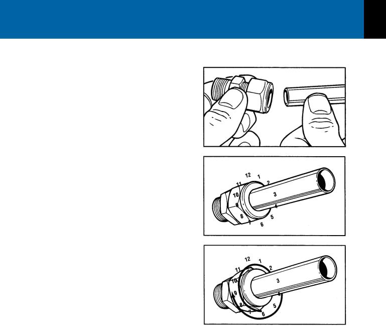
When SwagelokTube Fittings are used, the instructions for installation are:
1.Simply insert the tubing into the SwagelokTube Fitting. Make sure that the tubing rests firmly on the shoulder of the fitting and that the nut is finger-tight.
2.Before tightening the Swagelok nut, scribe the nut at the 6 o’clock position.
3.While holding the fitting body steady with a back-up wrench, tighten the nut 1-1/4 turns.
Watch the scribe mark, make one complete revolution and continue to the 9 o’clock position.
4.For 3/16” and 4mm or smaller tube fittings, tighten the Swagelok nut 3/4 turns from fingertight.
Swagelok tubing connections can be disconnected and retightened many times. The same reliable leakproof seal can be obtained every time the connection is remade using the simple two-step procedure.
1.Insert the tubing with pre-swaged ferrules into the fitting body until the front ferrule seats.
2.Tighten the nut by hand. Rotate the nut to the original position with a wrench. An increase in resistance will be encountered at the original position. Then tighten slightly with a wrench.
Smaller tube sizes (up to 3/16” or 4mm) take less tightening to reach the original position than larger tube sizes.
The type of tubing and the wall thickness also has an effect on the amount of tightening required. Plastic tubing requires a minimal amount of additional tightening while heavy wall metal tubing may require somewhat more tightening. In general, the nut only needs to be tightened about 1/8 turn beyond finger tight where the ferrule seats in order to obtain a tight seal.
Over tightening the nut should be avoided. Over tightening the nut causes distortion (flaring) of the lip of the tube fitting where the ferrule seats. This in turn causes the threaded portion of the body to deform. It becomes difficult to tighten the nut by hand during a subsequent re-tightening when the fitting body becomes distorted in this manner.
Installation 2
Figure 2-1
Swagelok Tube Fittings
w w w . p a r r i n s t . c o m |
11 |
2 Installation
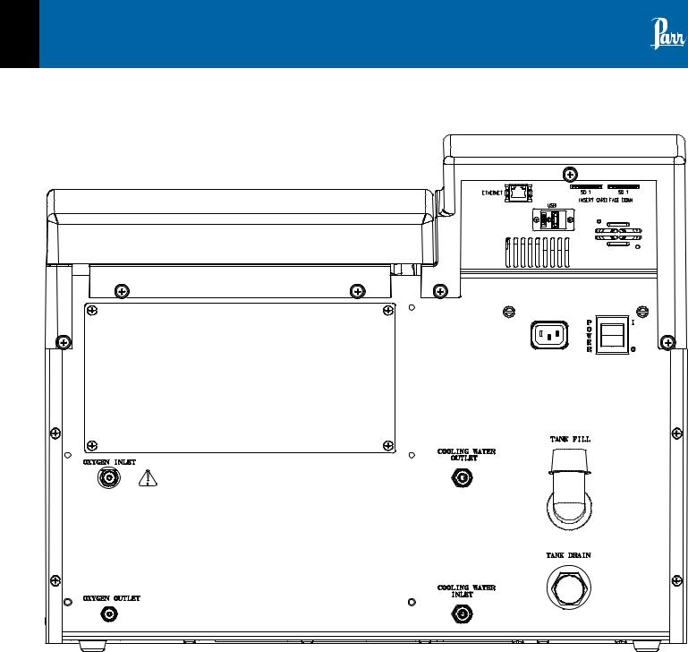
Figure 2-2
6200 Calorimeter Back Panel
12 |
P a r r I n s t r u m e n t C o m p a n y |

6200 |
Installation |
2 |
|
|
|
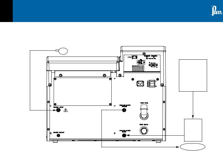
Figure 2-3
Closed Loop Configuration with 6510

 O2 Regulator
|
6510 Water |
Line 3 |
Handling |
System |
|
|
Line 2 |
|
Line 1 |
|
~27 °C |
|
Figure 2-4 |
|
Open Loop Configuration with Tap Water |
|
O2 Regulator |
Tap Water
· <27 °C
Line 3
Line 2
Line 1
Drain
Line 1 & 2 – Maximum length of 10 feet, 1/4” OD, Polyurethane (Part Number HJ0025TB035) Line 3 – Maximum length of 25 feet, 1/8” OD, Nylon (Part Number HX0012TB024)
w w w . p a r r i n s t . c o m |
13 |
2 Installation
Figure 2-5
Open Loop Configuration with 1552

 O2 Regulator
|
Tap Water |
|
Line 3 |
· >27 °C |
|
|
||
Line 2 |
1552 |
|
Line 1 |
Water |
|
Cooler |
||
~27 °C |
||
|
Drain |
Line 1 & 2 – Maximum length of 10 feet, 1/4” OD, Polyurethane (Part Number HJ0025TB035) Line 3 – Maximum length of 25 feet, 1/8” OD, Nylon (Part Number HX0012TB024)
14 |
P a r r I n s t r u m e n t C o m p a n y |
6200
Chapter 3
Instrument Description
Types of Controls
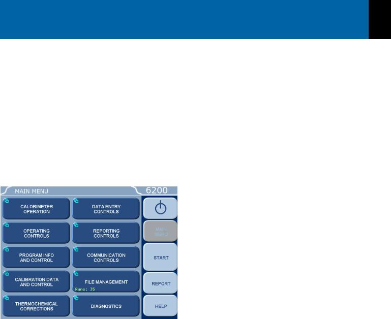
All calorimeter configurations and operations are handled by a menu-driven system operated from the bright touch screen display.The settings and controls are organized into nine main sections or pages which comprise the MAIN MENU.
Note: Keys with a “double box” in the upper left hand corner lead to sub-menus.
Menu Keys
The controls that change the data field information in the menus will be one of the following:
1.Toggles.These data fields contain ON/OFF or YES/NO choices. Simply touching the key on the screen toggles the choice to the other option. The current setting is displayed in the lower right corner of the key.
2.Option Selection.These data fields contain a list of options.Touching the key on the screen steps the user through the available choices. The current setting is displayed in the lower right corner of the key.
3.Value Entry Fields.These data fields are used to enter data into the calorimeter.Touching the key on the screen brings up a sub menu with a key
Instrument Description 3
pad or similar screen for entering the required value. Some keys lead to multiple choices. Always clear the current value before entering a new value. Once entered the screen will revert to the previous menu and the new value will be displayed in the lower right corner of the key.
4.Data Displays. Most of these keys display values that have been calculated by the calorimeter and are informational only. Certain ones can be overridden by the user entering a desired value through a sub-menu. The value is displayed in the lower right corner of the key.
Note: Some keys will respond with an opportunity for the user to confirm the specified action to minimize accidental disruptions to the program and/or stored data.
Control Keys
There are five control keys which always appear in the right column of the primary displays. These keys are unavailable when they are gray instead of white.
1.Escape. This key is used to go up one level in the menu structure.
2.Main Menu. This key is used to return to the main menu touch screen from anywhere in the menu structure.
3.Start. This key is used to start a calorimeter test.
4.Report. This key is used to access the test results stored in the calorimeter, to enter thermochemical corrections and to initiate report on the display, printer or attached computer.
5.Help. This key is used to access help screens related to the menu currently displayed on the touch screen.
6.Abort. This key appears in the start key location while the test is running. Pressing this key will abort the test in progress.
7. This key appears on the main menu only and is used to prepare the calorimeter for turning off the power.
w w w . p a r r i n s t . c o m |
15 |

Notes
16 |
P a r r I n s t r u m e n t C o m p a n y |

6200
Chapter 4
Program Installation & Control
Software Installation
The program in the 6200 Calorimeter can be extensively modified to tailor the unit to a wide variety of operating conditions, reporting units, laboratory techniques, available accessories and communication modes.
In addition, the calculations, thermochemical corrections, and reporting modes can be modified to conform to a number of standard test methods and procedures.
Numerous provisions are included to permit the use of other reagent concentrations, techniques, combustion aids and short cuts appropriate for the user’s work.
Note: Changes to the program are made by use of the menu structure described in Appendix A of this manual. Any of these items can be individually entered at any time to revise the operating program.
Default Settings
Units are pre-programmed with default settings. See pages 17 and 18 for a listing of the factory default settings.
These default settings remain in effect until changed by the user. Should the user ever wish to return
to the factory default settings, go to the Program
Information and Control Menu, then to User/Factory
Settings, and then touch Reload Factory Default Settings andYES.
Non-volatile memory is provided to retain any and all operator initiated program changes; even if power is interrupted or the unit is turned off. If the unit experiences an intentional or unintentional “Cold Restart”, the controller will return to its default settings.
Program Installation & Control 4
Revising Default Settings
The default parameters of the 6200 Calorimeter can be changed to guarantee that the 6200 Calorimeter, when cold restarted, will always be in the desired configuration before beginning a series of tests.
Users who wish to permanently revise their default settings may do so using the following procedure:
•Establish the operating parameters to be stored as the user default settings.
•Go to the Program Info and Control Menu, User/
Factory Settings, User Setup ID, and enter the desired User Setup ID.
•Select Save User Default Settings
To re-load the user default settings, go to the Program Info and Control Page, User/Factory Settings,
Re-load User Default Settings, andYES.
w w w . p a r r i n s t . c o m |
17 |

4 Program Installation & Control
Table 4-1
6200 Factory Default Settings
Calorimeter Operations
Operating Mode |
Determination |
Bomb Installed/EE |
1/2400.0 |
|
|
Heater and Pump |
OFF |
Operating Controls
Method of Operation |
Dynamic |
|
|
Reporting Units |
BTU/lb |
Use Spiking Correction |
OFF |
|
|
“OTHER” Multiplier |
4.1868 |
|
|
CalibrateTouchscreen |
|
LCD BacklightTimeout(s) |
1200 S |
LCD Backlight Intensity |
70% |
|
|
Print Error Messages |
ON |
|
|
Language |
English |
Spike Controls
Use Spiking |
OFF |
Heat of Combustion of Spike |
6318.4 |
|
|
Use Fixed Spike |
OFF |
|
|
Weight of Fixed Spike |
0.0 |
Prompt for Spike before Weight |
OFF |
Program Information and Control
Date &Time Settings
Volume Level Adjust |
85% |
Software and Hardware Info |
|
Settings Protect |
OFF |
|
|
User/Factory Settings |
|
Feature Key |
|
BombType Select |
|
|
|
User Function Setup |
|
|
|
Cold Restart |
|
User/Factory Settings
User Setup ID |
62-1108 |
Reload Factory Default Settings
Reload User Default Settings
Save User Default Settings
Calibration Data & Controls
Calibration Run Limit |
10 |
EE Max Std Deviation |
0.0 |
Heat of Combustion of Standard |
6318.4 |
|
|
Bomb Service Interval |
500 |
Control Chart Parameters |
|
Charted Value |
HOC Standard |
|
|
Process Sigma |
0.1 |
Temp Rise High Warning |
3.3 |
Temp Rise Low Warning |
2.0 |
|
|
Use Bomb |
1 |
Bomb 1 Through 4
EE Value |
2400.0 |
|
|
Protected EE Value |
OFF |
Thermochemical Corrections Standardization
Fixed Fuse Correction |
ON 50 |
Acid Correction |
Fixed HNO3 10.0 |
Fixed Sulfur Correction |
ON 0.0 |
|
|
Determination
Fixed Fuse Correction |
ON 50 |
|
|
Acid Correction |
Fixed HNO3 10.0 |
Fixed Sulfur Correction |
OFF 0.0 |
Net Heat/Dry Factors |
Net Heat & Dry Disable |
|
Fixed Hydrogen |
|
OFF 0.0 |
|
|
|
Fixed Oxygen |
|
ON 0.0 |
Fixed Nitrogen |
|
ON 0.0 |
Calculate Net Heat of Combustion |
OFF |
|
|
|
|
Fixed Moisture as Determined |
OFF 0.0 |
|
Fixed Moisture as Received |
|
OFF 0.0 |
Dry Calculation |
|
OFF |
|
|
|
18 |
P a r r I n s t r u m e n t C o m p a n y |
6200 |
|
Program Installation & Control |
4 |
|
|
|
|
|
|
|
Table 4-1 (Continued) |
|||
|
6200 Factory Default Settings |
|||
Calculation Factors |
|
Communication Controls |
|
|
Nitric Acid Factor |
1.58 |
Acid Multiplier |
0.0709 |
|
|
Sulfur Value is Percent |
ON |
Sulfur Multiplier |
0.6238 |
Fuse Multiplier |
1.0 |
|
|
Use Offset Correction (ISO) |
OFF |
|
|
Offset Value |
0.0 |
PrinterType |
Parr 1758 |
|
|
Balance Port |
|
Network Interface |
|
Printer Destination |
Local (USB) |
|
|
Bar Code Port |
|
|
|
Network Data Devices |
|
Balance Port Communications
Data Entry Controls
Prompt for Bomb ID |
ON |
|
|
Weight Entry Modes |
Touch Screen |
Acid Entry Mode |
Touch Screen |
Net Heat Entry Modes |
Touch Screen |
|
|
Auto Sample ID Controls |
ON |
|
|
Sample Weight Warning above |
2.0 |
Spike Weight Entry Mode |
Touch Screen |
|
|
Sulfur Entry Mode |
Touch Screen |
|
|
Moisture Entry Mode |
Touch Screen |
Auto Preweigh Controls |
ON |
|
|
Auto Sample ID Controls
Automatic Sample ID |
ON |
|
|
Automatic Sample ID Increment |
1 |
Automatic Sample ID Number |
1 |
|
|
Auto Preweigh Controls
Automatic Preweigh ID |
ON |
Automatic Preweigh ID Increment |
1 |
Automatic Preweigh ID Number |
1 |
|
|
Reporting Controls
Report Width |
40 |
Automatic Reporting |
ON |
Auto Report Destination |
Printer |
|
|
Individual Printed Reports |
OFF |
Edit Final Reports |
OFF |
Recalculate Final Reports |
OFF |
|
|
Use New EEValues in Recalculation |
OFF |
BalanceType |
Generic |
Balance Port Device |
|
|
|
Customize Balance Settings |
|
Balance Port Settings
Number of Data Bits |
8 |
Parity |
None |
|
|
Number of Stop Bits |
1 |
Handshaking |
None |
Baud Rate |
9600 |
|
|
Data Characters from Balance |
8 |
|
|
Data Precision |
4 |
TransferTimeout (seconds) |
10 |
|
|
Balance Handler Strings |
|
|
|
Data Logger
Data Logger |
OFF |
|
|
Data Log Interval |
12s |
Data Log Destination |
Log File and Printer |
|
|
Select Data Log Items |
|
|
|
Data Log Format |
Text Format |
w w w . p a r r i n s t . c o m |
19 |

Notes
20 |
P a r r I n s t r u m e n t C o m p a n y |

6200
Chapter 5
Operating Instructions
Operating the 1108P Oxygen Combustion Vessel
Detailed instructions for preparing the sample and charging the 1108P Oxygen Combustion Vessels are given in Operating Instructions No. 418M. Follow these instructions carefully, giving particular attention to the precautions to be observed in charging and handling the bomb.
Operating the Filling Connection
To fill the bomb, connect the hose to the bomb inlet valve and push the O2 Fill button on the calorimeter control panel.The calorimeter will then fill the bomb to the preset pressure and release the residual pressure in the connecting hose at the end of the filling cycle. It will take approximately 60 seconds to fill the bomb. During this time a countdown timer on the O2 fill button will display the remaining fill time. Pushing the O2 key a second time will stop the flow of oxygen at any time. Once the display returns to its normal reading, the user can disconnect the coupling and proceed with the combustion test.
If the charging cycle should be started inadvertently, it can be stopped immediately by pushing the O2 FILL key a second time.
During extended periods of inactivity, overnight or longer, close the tank valve to prevent leakage. When changing oxygen tanks, close the tank valve
and push the O2 FILL key to exhaust the system. Do not use oil or combustible lubricants on this filling system or on any devices handling oxygen under pressure. Keep all threads, fittings, and gaskets clean and in good condition. Replace the two 394HCJE O-rings in the slip connector if the connector fails to maintain a tight seal on the bomb inlet valve.
The recommended filling pressure is 450 psig (3 MPa or 30 bar).This pressure is prescribed by most of the standard bomb calorimetric test methods. Higher or lower filling pressures can be used, but the bomb must never be filled to more than 600 psig (40 atm).
Operating Instructions 5
Operating the Calorimeter
All operations required to standardize the 6200 Calorimeter, or test an unknown sample, should proceed step-wise in the following manner:
1.Turn on the calorimeter and activate the pump and heater using Calorimeter Operations. Allow at least 20 minutes for the calorimeter to warm up and the jacket temperature to stabilize. Once the jacket temperature comes within 0.5 °C of 30 °C and stays there for approximately 15 minutes, the calorimeter is ready to begin testing.
The Start key will be available at this time.The bomb parts should be wetted and then dried in the manner used at the conclusion of a test. This serves to wet all sealing parts as well as leaving the bomb with the same amount of residual water which will exist in all subsequent testing.
2.Prepare the sample weighing the material to 0.1 mg and charge the oxygen bomb as described in the section entitled Operating the Filling Connection. Using an additional bomb and bucket can increase the throughput of the 6200 Calorimeter. With this arrangement, the calorimeter can operate almost continuously since the operator will be able to empty a bomb and recharge it while a run is in progress. A bomb and bucket for the next run will be ready to go into the calorimeter as soon as it is opened. Each bomb and bucket combination will have to be standardized separately and the proper energy equivalent for each set must be used when calculating the heat of combustion.
3.Fill the calorimeter bucket by first taring the dry bucket on a solution or trip balance; then add
2000 (+/- 0.5) grams of water. Distilled water is preferred, but demineralized or tap water containing less than 250 ppm of dissolved solids is satisfactory. The bucket water temperature should be approximately 3 to 5 °C below the jacket temperature. It is not necessary to use exactly 2000 grams, but the amount selected must be duplicated within +/- 0.5 gram for each run. Instead of weighing the bucket, it can be
filled from an automatic pipet, or from any other volumetric device if the repeatability of the filling system is within +/- 0.5 ml.
w w w . p a r r i n s t . c o m |
21 |

5 Operating Instructions
To speed and simplify the bucket filling process, and to conserve water and energy, Parr offers
a closed circuit Water Handling System (No. 6510). This provides a water supply, cooled to the starting temperature and held in an automatic pipet ready for delivery in the exact amount needed to fill the bucket. Instructions
for this automatic system are given in Operating Instruction No. 454M.
4.Set the bucket in the calorimeter. Attach the lifting handle (421A) to the two holes in the side of the screw cap and partially lower the
bomb into the water. Handle the bomb carefully during this operation so that the sample will not be disturbed. Push the two ignition lead wires into the terminal sockets on the bomb head. Orient the wires away from the stirrer shaft
so they do not become tangled in the stirring mechanism. Lower the bomb completely into water with its feet spanning the circular boss in the bottom of the bucket. Remove the lifting handle and shake any drops of water back into the bucket and check for gas bubbles.
Note: If bubbles continue to rise from the bomb after the air in the screw cap has escaped the test must be stopped and the bomb not fired until the leak has been corrected.
5.Close the calorimeter cover. This lowers the stirrer and thermistor probe into the bucket. Make sure that the bucket thermistor does not touch the bucket or 1108P when the lid is lowered.
6.Select determination or standardization as appropriate on the Calorimeter Operation menu by toggling the OPERATING MODE key. After pressing the START key, the calorimeter will now prompt the operator for Bomb ID number, sample ID number, sample weight and spike weight in accordance with the instructions set into the operating controls page.
7.The calorimeter will now take over and conduct the test. During the time it is establishing the initial equilibrium, it will display PREPERIOD on
the status bar. Just before it fires the bomb, it will sound a series of short beeps to warn the user to move away from the calorimeter. Once the bomb has been fired, the status bar will display POSTPERIOD. The calorimeter will check to make certain that a temperature rise occurs and will then look for the final equilibrium conditions to be met. If it fails to meet either the initial or final equilibrium conditions, or if it fails to detect a temperature rise within the allotted time, the calorimeter will terminate the test and advise the user of the error.
8.At the conclusion of the test, the calorimeter will signal the user.
9.Open the cover and remove the bomb and bucket. Remove the bomb from the bucket and open the knurled valve knob on the bomb
head to release the residual gas pressure before attempting to remove the cap. This release should proceed slowly over a period of not less than one minute to avoid entrainment losses. After all pressure has been released, unscrew the cap, lift the head out of the cylinder and examine the interior of the bomb for soot or other evidence of incomplete combustion. If such evidence is found, the test will have to be discarded. Otherwise, wash all interior surfaces of the bomb, including the head, with a jet of distilled water and collect the washings in a beaker.
10.Titrate the bomb washings with a standard sodium carbonate solution using methyl orange, red or purple indicator. A 0.0709N sodium carbonate solution is recommended for this titration to simplify the calculation. This is
prepared by dissolving 3.76 grams of Na2CO3 in the water and diluting to one liter. NaOH or KOH solutions of the same normality may be used.
11.Analyze the bomb washings to determine the sulfur content of the sample if it exceeds 0.1%. Methods for determining sulfur are discussed in Operating Instructions No. 207M.
12.At the end of the testing period, turn OFF the calorimeter at the power switch.
22 |
P a r r I n s t r u m e n t C o m p a n y |
6200 |
Operating Instructions |
5 |
|
|
|
Samples and Sample Holders
Particle Size and Moisture Content. Solid samples burn best in an oxygen bomb when reduced to 60 mesh, or smaller, and compressed into a pellet with a 2811 Parr Pellet Press.
Large particles may not burn completely and small particles are easily swept out of the capsule by turbulent gases during rapid combustion.
Note: Particle size is important because it influences the reaction rate. Compression into a pellet is recommended because the pressure developed during combustion can be reduced as much as 40% when compared to the combustion of the material in the powder form. In addition in giving controlled burn rates, the pelletizing of samples keeps the sample in the fuel capsule during combustion.
Materials, such as coal, burn well in the as-received or air-dry condition, but do not burn completely dry samples. A certain amount of moisture is desirable in order to control the burning rate. Moisture content up to 20% can be tolerated in many cases, but the optimum moisture is best determined by trial combustions.
If moisture is to be added to retard the combustion rate, drop water directly into a loose sample or onto a pellet after the sample has been weighed.Then let the sample stand for awhile to obtain uniform distribution.
Combustion Aids
Some samples may be difficult to ignite or they may burn so slowly that the particles become chilled below the ignition point before complete combustion is obtained. In such cases benzoic acid, white oil or any other combustible material of known purity can be mixed with the sample. Ethylene glycol, butyl alcohol or decalin may also be used for this purpose.
Note: It must be remembered, however, that a combustion aid adds to the total energy released in the bomb and the amount of sample may have to be reduced to compensate for the added charge.
Also, when benzoic acid is combusted for standardization runs or for combustion aid purposes, it should be in the form of a pellet to avoid possible damage to the bomb which might result from rapid combustion of the loose powder.
Oxygen Charging Pressure
The 6200 Calorimeter has been designed to operate with an oxygen filling pressure of 30 atm. Significant changes from this value are not recommended.
Combustion Capsules
Non-volatile samples to be tested in Parr oxygen bombs are weighed and burned in shallow capsules measuring approximately 1” diameter and 7/16” deep.These are available in stainless steel, fused silica, fused quartz, and platinum alloyed with
3-1/2% rhodium.
Stainless steel capsules 43AS are furnished with each calorimeter. When combusting samples that contain metal particles such as aluminum or magnesium, the non-metallic fused silica 43A3 capsule or fused quartz 43A3KQ capsule is required. When superior corrosion resistance is needed, the platinum rhodium 43A5 capsule is required.
The stainless steel capsules will acquire a dull gray finish after repeated use in an oxygen bomb due to the formation of a hard, protective oxide film.This dull finish not only protects the capsule, but it also promotes combustion and makes it easier to burn the last traces of the sample.
Capsules should be monitored for wear. Do not use the capsule if the wall or base thickness is less than 0.025”.
New capsules are heated in a muffle furnace at 500 ºC for 24 hours by Parr to develop this protec-
tive coating uniformly on all surfaces.This treatment should be repeated after a capsule has been polished with an abrasive to remove any ash or other surface deposits. Heating in a muffle is also a good way to destroy any traces of carbon or combustible matter which might remain in the capsule from a previous test.
Note: After heating, place the capsules in a clean container and handle them only with forceps when they are removed to be weighed on an analytical balance.
w w w . p a r r i n s t . c o m |
23 |

5 Operating Instructions
Foodstuffs and Cellulosic Materials
Fibrous and fluffy materials generally require one of three modes of controlling the burn rate. Fibrous materials do not pelletize readily and generally require either moisture content or a combustion aid such as mineral oil to retard the burn rate and avoid development of high pressures.
Partial drying may be necessary if the moisture content is too high to obtain ignition, but if the sample is heat sensitive and cannot be dried, a water soluble combustion aid such as ethylene glycol can be added to promote ignition.
Coarse Samples
In most cases it may be necessary to burn coarse samples without size reduction since grinding or drying may introduce unwanted changes.There is no objection to this if the coarse sample will ignite and burn completely. Whole wheat grains
and coarse charcoal chunks are typical of materials which will burn satisfactorily without grinding and without additives or a special procedure.
Corrosive Samples
The 1108P Oxygen Combustion Vessel is made of a corrosion resistant alloy designed to withstand the corrosive mixture of sulfuric and nitric acids produced in normal fuel testing operations. Samples containing chlorine and particular samples containing more than 20 mg of chlorine samples with high sulfur contents will greatly accelerate corrosion of the bomb. An alternate 1108PCL is available constructed of an alloy selected to specifically resist the corrosive effects of samples with high chlorine or chloride.
While no material will offer complete corrosion resistance to these samples, the 1108PCL offers significantly enhanced corrosion resistance for this service.
Explosives and High Energy Fuels
The 1108P and 1108PCL used in the 6200 Calorimeter have been designed to provide highly automated testing of routine samples. Materials which release large volumes of gas which detonate with explosive force or burn with unusually high energy levels should not be tested with these bombs. Rather, they should be tested in a model 1104 High Pressure Oxygen Combustion Vessel designed specifically for these types of samples.
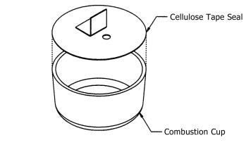
Volatile Sample Holders
Volatile samples can be handled in a Parr 43A6 platinum capsule with a spun rim, or in a Parr 43AS stainless steel capsule which has a sturdy wall with a flat top rim.These holders can be sealed with a disc of plastic adhesive tape prepared by stretching tape across the top of the cup and trimming the excess with a sharp knife.The seal obtained after pressing this disc firmly against the rim of the cup with a flat blade will be adequate for most volatile samples.
The tape used for this purpose should be free of chlorine and as low in sulfur as possible. Borden MysticTape, No. M-169-C or 3MTransparentTape, No. 610, are recommended for this purpose.The 3M TransparentTape can be ordered through Parr, Part No. 517A.
The weight of the tape disc must be determined separately and a correction applied for any elements in the tape which might interfere with the determination.The approximate Heat of Combustion of the tape is 6300 cal/g. An actual amount should be determined by running a blank test with tape alone using a sample weighing 1.0 gram.The compensation for heat of tape may be done through the spike option; see Spike Controls, Line 2 - Heat of Combustion of Spike.
Note: Tape should always be stored in a sealed container to minimize changes in its moisture and solvent content.
24 |
P a r r I n s t r u m e n t C o m p a n y |
6200 |
Operating Instructions |
5 |
|
|
|
Figure 5-7
Combustion Capsule with Adhesive Tape Seal
Use the following procedure when filling and handling any of these tape-sealed sample holders:
•Weigh the empty cup or capsule; then cover the top with tape, trim with a knife and press the trimmed edge firmly against the metal rim. Also cut and attach a small flag to the disc (see Figure 5-7).
•Puncture the tape at a point below the flag, then re-weigh the empty cup with its tape cover.
•Add the sample with a hypodermic syringe; close the opening with the flag and re-weigh the filled cup.
•Set the cup in the capsule holder and arrange the auxiliary fuse so that it touches the center of the tape disc.
•Just before starting the test, prick the disc with a sharp needle to make a small opening which is needed to prevent collapse of the disc when pressure is applied.
•Fill the bomb with the usual oxygen charging pressure.
•The calorimeter will fire the bomb and complete the test in the usual manner.
Volatile samples are defined as one with an initial boiling point below 180 °C per ASTM D-2.
Low volatile samples with a high water content, such as urine or blood, can be burned in an open capsule by absorbing the liquid on filter paper pulp or by adding a combustion aid, such as ethylene glycol.
Poor Combustion
Because of the difference in combustion characteristics of the many different materials which may be burned in an oxygen bomb, it is difficult to give specific directions which will assure complete combustions for all samples.
The following fundamental conditions should be considered when burning samples:
•Some part of the sample must be heated to its ignition temperature to start the combustion and, in burning, it must liberate sufficient heat to support its own combustion regardless of the chilling effect of the adjacent metal parts.
•The combustion must produce sufficient turbulence within the bomb to bring oxygen into the fuel cup for burning the last traces of the sample.
•Loose or powdery condition of the sample which will permit unburned particles to be ejected during a violent combustion.
•The use of a sample containing coarse particles which will not burn readily. Coal particles which are too large to pass a 60 mesh screen may not burn completely.
•The use of a sample pellet which has been made too hard or too soft. Either condition can cause spalling and the ejection of unburned fragments.
•Insufficient space between the combustion cup and the bottom of the bomb.The bottom of the cup should always be at least one-half inch above the bottom of the bomb or above the liquid level in the bomb to prevent thermal quenching.
•Excessive moisture or non-combustible material in the sample. If the moisture, ash and other non combustible material in the sample amounts to approximately 20% or more of the charge, it may be difficult to obtain complete combustion.This condition can be remedied by adding a small amount of benzoic acid or other combustion aid.
w w w . p a r r i n s t . c o m |
25 |
Loading...