Parr Instrument Bottom Drain Valves User Manual

Operating & Maintenance Instruction Manual |
490M |
Bottom Drain Valves
Models A465VB, A465VB2, A485VB, A485VB2 & A560VB
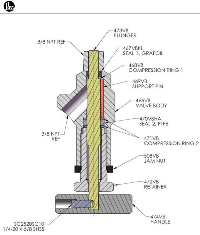
Description
The Parr Instrument Company bottom drain valve is a rising stem, process sampling valve. In the closed position, the stem of the valve is flush with the inside bottom of the vessel so that there is a minimum of dead space between the bottom of the vessel and the shut off point of the valve. In the fully open position, the stem is retracted completely to open a clear passage from the vessel. When the valve is re-closed, any material in this passage will be pushed back into the reactor by the rising stem. As the plunger moves to the closing end of the stroke, a seal is established as the plunger contacts the compression ring and compresses the seal.
Installation and Operation
These valves are designed to be installed in the bottom of Parr cylinders that are machined specifically for installation with a minimum of dead space. Pipe thread sealant tape should be applied to the valve body threads and then installed turning clockwise into the cylinder. The valve should be tightened sufficiently to seal the pipe threads and bring the stem of the valve approximately even with the inside bottom of the cylinder.
The valve is opened by turning the handle counterclockwise. The more turns open; the valve will provide a larger passage for product flow.
The valve is closed by turning the handle clockwise until the plunger meets the compression ring and compresses the seal.
Typical torque values on the valve handle required to seal the valves are as follows:
A465VB |
10 – 15 ft/lbs |
|
A465VB2 |
10 |
– 15 ft/lbs |
A485VB |
5 |
– 10 ft/lbs |
A485VB2 |
5 |
– 10 ft/lbs |
A560VB |
15 |
– 20 ft/lbs |
Significantly more torque should not be required to seal the valves. If the valve is leaking, it is a good indication that the seal is worn or has been damaged. The valve should be disassembled, inspected, cleaned as required and seals replaced.
Disassembly of the Bottom Drain Valves
1.Retract the plunger to the fully open position by turning the handle counterclockwise.
2.Loosen the jam nut from the valve body by turning it counterclockwise in relation to the valve body.
3.Loosen the retainer by turning it counterclockwise in relation to the valve body until its threads are clear of the valve body.
4.Pull the plunger, handle, and retainer out of the valve body together.
5.Remove the lower compression rings and seal. Inspect these parts for wear and replace if necessary.
6.Remove the support pin from the valve body.
7.Remove the upper compression ring and seal. Inspect these parts for wear and replace if necessary.
-1 -

Bottom Drain Valves Models A465VB, A465VB2, A485VB & A560VB Operating Instruction Manual
Assembly of Bottom Drain Valves
1. Before assembly, all parts of the valve should be clean and in good condition.
Note: Assembly of the valve is easier if it is removed from service and oriented so that the threads going into the cylinder face downwards.
2.Install a PTFE upper seal into the cavity in the valve body. The plunger may be used to help with the installation.
3.Install a small compression ring behind the PTFE upper seal.
4.Install the pin into the groove. The pin will rest on the upper compression ring.
5.Install one larger compression ring followed by a PTFE upper seal, and then the final compression ring is installed into the proper recesses in the valve body.
6.Apply generous amounts of lubrication using a high temperature thread lubricant. See the “Lubrication of the Bottom Drain Valves” section in this manual. Apply lubrication to the following threads:
The outer threads of the plunger. The inner threads of the retainer.
The inner threads of the valve body where the retainer will go. The outer threads of the retainer.
7.Install the jam nut as far as it will go onto the threads of the retainer.
8.Screw the plunger about half of the way into the retainer.
9.Guide the retainer and plunger combination into the valve body until the threads of the retainer engage with the valve body.
10.Continue tightening the retainer until it is hand tight.
11.Install the handle onto the plunger with the pin and set screw.
12.Rotate the handle clockwise until the plunger extends as high as it will go.
13.Loosen the plunger by turning the handle counterclockwise one complete turn.
14.Tighten the retainer into valve body to the following torque:
A465VB |
20 ft/lbs |
A465VB2 |
20 ft/lbs |
A485VB |
15 ft/lbs |
A485VB2 |
15 ft/lbs |
A560VB |
20 ft/lbs |
15.Tighten the jam nut on the retainer until it comes into contact with the valve body.
16.Tighten the valve handle clockwise until the plunger is in the fully engaged position.
Lubrication of the Bottom Drain Valves
Lubrication of the threads should be done with a nickel based high temperature thread lubricant. Lubricate all inner and outer straight threads on the valve body, retainer and plunger.
The frequency of lubrication depends on the amount of use the valve receives. If the valve sits for a long period of time (one or more months), it should be lubricated before use. If the valve is used daily, then lubrication may be required once a week.
Applications that include operating temperatures of 250°C and above will require more frequent lubrication of the valve threads.
- 2 -

Bottom Drain Valves Models A465VB, A465VB2, A485VB & A560VB Operating Instruction Manual
A465VB
* Available in other alloys
- 3 -
 Loading...