Parr Instrument 1341 User Manual

204M
1341
Plain Jacket Calorimeter
Operating Instruction Manual

Table of Contents
Preface
Scope
Related Instructions
Important Information Intended Usage Explanation of Symbols Safety Information General Specifications Environmental Conditions
Provisions for Lifting and Carrying
Assemble the Calorimeter
Operating the 1108 Oxygen Vessel
Operating the Calorimeter
Calculating the Heat of Combustion
Assembly of Data
Temperature Rise
Gross Heat of Combustion
Conversion to Other Bases
Standardizing the Calorimeter
The Energy Equivalent Factor
Standard Samples
Standardization Procedure
3
3
3
3
3
4
4
4
4
4
5
5
6
8
8
8
9
9
10
10
10
10
Discussion of Calculations |
11 |
|
|
Acid Correction |
11 |
Sulfur Correction |
11 |
Fuse Wire Correction |
11 |
Radiation Correction |
11 |
Magnitude of Errors |
12 |
Maintenance |
12 |
||
|
|
|
|
Calorimeter Maintenance |
12 |
||
General Cleaning Instructions |
12 |
||
Fuse Ratings |
12 |
||
Electric Ignition Problems |
12 |
||
|
|
|
|
6772 Calorimetric Thermometer |
13 |
||
|
|
|
|
|
|
|
|
Electrical Hookup of Thermometer to Calorimeter |
14 |
||
|
|
|
|
|
|
|
|
Parts for the 1341 Calorimeter |
15 |
||
|
|
|
|
|
|
|
|
|
Customer Service |
|
|
|
Questions concerning the installation or operation |
|
|
|
of this instrument can be answered by the Parr |
|
|
|
Customer Service Department: |
|
|
|
1-309-762-7716 • 1-800-872-7720 |
|
|
|
Fax: 1-309-762-9453 |
|
|
|
E-mail: parr@parrinst.com |
|
|
|
www.parrinst.com |
|
|
|
|
|
|
|
|
|
|
2 |
P a r r I n s t r u m e n t C o m p a n y |

Preface
Scope
These instructions cover the steps to be taken in setting up and operating a Parr 1341 Plain Jacket Calorimeter. The user should study these instructions carefully before starting to use the calorimeter so that they will fully understand the capabilities of the equipment, and be well aware of the safety precautions to be observed in its operation. Instructions covering the operation of the 1108 Oxygen Combustion Vessel and the use of other related apparatus are provided in separate instruction manuals listed below. The separate manuals which apply to a particular calorimeter installation should be added to and made a part of these instructions.
Related Instructions
No. Description
205M Operating Instructions for the 1108 Oxygen Combustion Vessel
207M Analytical Methods for Oxygen Bombs
545M Operating Instructions for 6775/6775A DigitalThermometer
201M Limited Warranty
1341 Plain Jacket Calorimeter
Important Information
Your Parr 1341 Plain Jacket Calorimeter has been designed with function, reliability, and safety in mind. It is your responsibility to install it in conformance with local electrical codes.
This manual contains important operating and safety information.You must carefully read and understand the contents of this manual prior to the use of this equipment. For safe operation, please pay attention to the alert signals throughout the manual.
Intended Usage
Do not use this equipment for anything other than its intended usage. Protection provided by the equipment may be impaired if used in a manner not specified by Parr Instrument Company.This instrument is to be used indoors.
Note About Nomenclature:
Historically, burning a sample enclosed in a high pressure oxygen environment is known as Oxygen Bomb Calorimetry and the vessel containing the sample is known as an Oxygen Bomb. The terms bomb and vessel are used interchangeably.
w w w . p a r r i n s t . c o m |
3 |

1341 Plain Jacket Calorimeter
Explanation of Symbols
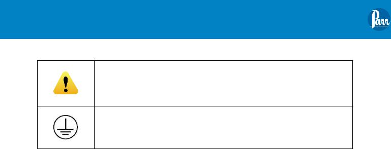
This CAUTION symbol may be present on the Product Instrumentation and literature. If present on the product, the user must consult the appropriate part of the accompanying product literature for more information.
Protective Earth (PE) terminal. Provided for connection of the Protective
Earth (green or green/yellow) supply system conductor.
Safety Information
To avoid electrical shock, always:
1.Use a properly grounded electrical outlet of correct voltage and current handling capability.
2.Ensure that the equipment is connected to electrical service according to local national electrical codes. Failure to properly connect may create a fire or shock hazard.
3.For continued protection against possible hazard, replace fuses with same type and rating of fuse.
4.Disconnect from the power supply before maintenance or servicing.
To avoid personal injury:
1.Do not use in the presence of flammable or combustible materials; fire or explosion may result.This device contains components which may ignite such material.
2.Refer servicing to qualified personnel.
General Specifications
Electrical Ratings
Plain Jacket Calorimeters:
Model 1341EB: 115VAC, 0.30 Amps, 60 Hz
Model 1341EE: 230VAC, 0.15 Amps, 50/60 Hz
Ignition Units:
2901EB: 115 VAC, 50/60 Hz, 4.0 Amps 2901EE: 230 VAC, 50/60 Hz, 2.0 Amps 2901EU: 230 VAC, 50/60 Hz, 2.0 Amps 2901EX: 230 VAC, 50/60 Hz, 2.0 Amps 2901EZ: 230 VAC, 50/60 Hz, 2.0 Amps
Before connecting the calorimeter to an electrical outlet, the user must be certain that the electrical outlet has an earth ground connection and that the line, load and other characteristics of the installation do not exceed the following limits:
Voltage: Fluctuations in the line voltage should not exceed 10% of the rated nominal voltage shown on the data plate.
Frequency: Calorimeters can be operated from either a 50 or 60 Hertz power supply without affecting their operation or calibration.
Current: The total current drawn should not exceed the rating shown on the data plate on the calorimeter by more than 10 percent.
Environmental Conditions
Operating: 15 ºC to 40 ºC; maximum relative humidity of 80% non-condensing.
Installation Category II (over voltage) in accordance with IEC 664.
Pollution degree 2 in accordance with IEC 664.
Altitude Limit: 2,000 meters.
Storage: -25 ºC and 65 ºC; 10% to 85% relative humidity.
Provisions for Lifting and Carrying
Before moving the instrument, disconnect all connections from the rear of the apparatus. Lift the instrument by grabbing underneath each corner.
4 |
P a r r I n s t r u m e n t C o m p a n y |

Assemble the Calorimeter
1.Unpack the calorimeter carefully and check the individual parts against the packing list. If shipping damage is discovered, report it immediately to the delivering carrier. Unpack the jacket first and set it on a sturdy bench or table in a location that is reasonably free from drafts and is protected from sources of radiant heat, preferably in an air conditioned room. Temperature changes in the room should be minimal.
There should be convenient access to running water, to a drain and to an appropriate grounded electrical outlet. About 8 square feet of workspace will be required. Access to a chemical balance sensitive to 0.1 mg and to a solution, trip or torsion balance capable of weighing up to 3.0 kg with 0.1 g sensitivity will be required. A standard 1A cylinder with a purity of 99.5% is usually sufficient for bomb combustion purposes.
2.Set the cover on the jacket. Remove the two screws from the side of the jacket and attach the stirrer drive motor. Check the stirrer shaft to be sure that it turns freely and slip the drive belt onto the motor and stirrer pulleys.
3.Assemble the cover support stands. Two stands are furnished, each consisting of a base, a support rod and ring to be clamped to the upper end of the rod. The A37A stand with the large ring is used to support the calorimeter cover when it is removed from the jacket, while the A38A stand with the smaller ring supports the bomb head when attaching the fuse wire and arranging the fuel capsule.
4.Install the thermistor by sliding it through the opening in the calorimeter cover. Adjust the length of the thermistor to match the length of the stirring shaft. Hand tighten the nut to secure the thermistor.
Note: Do not over tighten the nut.
Once installed, the thermistor can remain attached to the cover during all operations. Do not lay the cover on the tabletop. Always set it in the supporting ring on the A37A stand to protect the thermistor and stirring shafts.
5.Check the calorimeter bucket, noting the three dimples in the bottom of the bucket which rest on supporting pins in the bottom of the jacket.
1341 Plain Jacket Calorimeter
The single dimple must always face forward when setting the bucket in the jacket.
6.Connect the ignition unit. While any electrical system capable of furnishing approximately 23 volts can be used to ignite the fuse in the oxygen bomb, most users will prefer to use a Parr 2901 Ignition Unit for this purpose. This unit operates from any standard electrical outlet to provide the proper low voltage firing current, providing also a convenient push switch, indicating lamp and connecting terminals.
Connect one of the lead wires from the calorimeter jacket to the terminal labeled “10CM”. Connect the second lead to the terminal labeled “Common”. Plug the power cord into an appropriately grounded electrical outlet. The power supply cord is the main electrical disconnect device for the ignition unit. After the unit has been plugged into an outlet do not press the firing button unless the lead wires inside the jacket are connected to the combustion vessel.
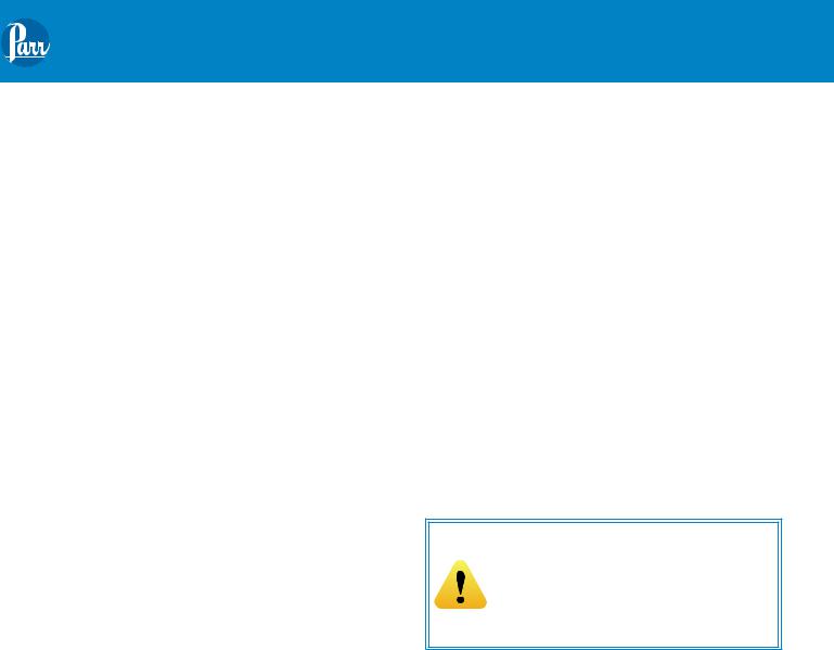
Caution!
If the bare terminals on these wires happen to be in contact with each other or with a metal object when the circuit is closed, the resulting short-circuit may cause serious damage to the ignition system.
7.Attach the oxygen filling connection. Unscrew the protecting cap from the oxygen tank and inspect the threads on the valve outlet to be sure they are clean and in good condition. Place the ball end of the 1825 Oxygen Filling Connection into the outlet socket and draw up the union
nut tightly with a wrench, keeping the 0-55 atm. gage in an upright position.
Operating instructions for the 1825 Oxygen Filling Connection are provided in Instruction Manual 205M for the 1108 Oxygen Combustion Vessel.
Operating the 1108 Oxygen Vessel
Detailed instructions for preparing the sample and charging the 1108 Oxygen Combustion Vessel are given in Instruction Manual, No. 205M. Follow these instructions carefully, giving particular attention to the precautions to be observed in charging and handling the bomb.
w w w . p a r r i n s t . c o m |
5 |
 Loading...