


 Loading...
575M
4848B
Reactor Controller
Operating Instruction Manual

Table of Contents
Preface
Related Instructions — 4 Scope — 4 Applications — 4
Explanation of Symbols — 5 Safety Information — 5 Intended Usage — 5 Cleaning & Maintenance — 5 General Specifications — 6
Environmental Conditions — 6 Provisions for Lifting and Carrying — 6
4848B Reactor Controller Specifications — 6 User’s Responsibility — 7
Unpack Carefully — 7
Installation
General Instructions — 8
Connections — 8
Component Summary
Switches and Indicators — 9
Protective Fuses and Relays — 10
High Limit Reset— 11
Access to the Controller Cabinet— 11
Fuses— 11
Instructions for the 4848B Reactor Controller
Temperature Control Module — 12
Temperature Control— 12
HighTemperature Alarm Setpoint— 12 PID groups— 12
Autotuning— 13
Temperature Profiles - Ramp and Soak— 13 Engaging a Program— 14
AdjustmentsTo Speed Control Board— 19 Solenoid Valve Module — 19
Communication with PC — 20
Quick Start Instructions for Connecting with PC— 20 Datalogging and Charting— 21
Converting a Chart File toTXT— 21
4848B Factory Defaults
Navigating the Menu System/Factory Default Settings
— 22
PrimaryTemperature Module — 22 TDM / MCM Module — 23 Pressure Module — 23 HTM/ETLM Module — 24
MTM Module — 25
Appendix A: Controller Parameters
Initial Setting Mode — 26
Operation Mode — 27
Regulation Mode — 28
Parts List
Fuses — 29 Communication — 29 Cooling Solenoids — 29
PrimaryTemperature Module — 30 Pressure Display Module (PDM) — 30 Tachometer Module (TDM) — 31
or Motor Control Module (MCM) — 31 Hi-Temp Cut-Off Module (HTM) — 31
or ExternalTemperature Limit Module (ETLM) — 31
Visit our website to find our Controller FAQ http://www.parrinst.com/support/48484838-controller-support/controller-faq/
w w w . p a r r i n s t . c o m |
1 |

4848B Reactor Controller
Preface
Related Instructions
The following Parr publications are also included to further your understanding of this instrument and its component parts:
No. Description
201M Limited Warranty
576M 4848B Controller CD
Scope
These instructions cover the installation, operation and maintenance of Parr Model 4848B Reactor Controller as used with Parr laboratory reactors and pressure vessels. They cover the basic functions provided in each of these controllers and describe the several optional control modules which can be added to these expandable units. The users should study the instructions carefully before using any of these controllers so that they will fully understand the capabilities and limitations of this equipment and the safety precautions to be observed in its operation.
Applications
Each 4848B Reactor Controller consists of a packaged temperature control unit completely wired and assembled with appropriate power and safety relays, switches and pilot lights.
These units are designed specifically for use with Parr reactors and pressure vessels and are to be used only with Parr equipment.
Controllers furnished with Parr reactors equipped with variable speed, DC motors have a motor switch and a speed control knob on the front panel. Controllers to be used with AC equipment or an air motor do not have a speed control knob.
Customer Service
Questions concerning the installation or operation of this instrument can be answered by the Parr Customer Service Department:
1-309-762-7716 • 1-800-872-7720 • Fax: 1-309-762-9453
E-mail: parr@parrinst.com • http://www.parrinst.com
2 |
P a r r I n s t r u m e n t C o m p a n y |
4848B Reactor Controller
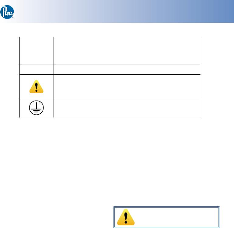
Explanation of Symbols
II |
On position, full power heater switch |
|
|
I |
On position, half power heater switch |
|
|
O |
Off Position |
~Alternating Current (AC)
This CAUTION symbol may be present on the Product Instrumentation and literature. If present on the product, the user must consult the appropriate part of the accompanying product literature for more information.
Protective Earth (PE) terminal. Provided for connection of the protective earth (green or green/yellow) supply system conductor.
Safety Information
To avoid electrical shock, always:
1.Use a properly grounded electrical outlet of correct voltage and current handling capability.
2.Ensure that the equipment is connected to electrical service according to local national electrical codes. Failure to properly connect may create a fire or shock hazard.
3.For continued protection against possible hazard, replace fuses with same type and rating of fuse.
4.Disconnect from the power supply before maintenance or servicing.
To avoid personal injury:
5.Do not use in the presence of flammable or combustible materials; fire or explosion may result. This device contains components which may ignite such material.
6.Refer servicing to qualified personnel.
Intended Usage
This controller has been designed for use with Parr pressure vessels and reactors. It has been designed, built, and tested to strict physical and electrical standards. However, it is the user’s responsibility to install and operate it in conformance with local pressure and electrical codes.
If the instrument is used in a manner not specified by Parr Instrument Company, the protection provided by the equipment may be impaired.
Cleaning & Maintenance
Periodic cleaning may be performed on the exterior surfaces of the controller with a lightly dampened cloth containing mild soap solution. All power should be disconnected and the power cord should be unplugged when cleaning the 4848B Controller.
There are no user serviceable parts inside the product other than what is specifically called out and discussed in this manual. Advanced troubleshooting instructions beyond the scope of this manual can be obtained by calling Parr Instrument Company in order to determine which part(s) may be replaced or serviced.
Ensure that any hot surfaces have had adequate time to cool before cleaning or maintaining the reactor and/or its components.
w w w . p a r r i n s t . c o m |
3 |
4848B Reactor Controller
General Specifications
Electrical Ratings
115VAC, 15.0 Amps, 50/60 Hz
230VAC, 15.0 Amps, 50/60 Hz
Before connecting a controller to an electrical outlet, the user must be certain that the electrical outlet has an earth ground connection and that the line, load and other characteristics of the installation do not exceed the following limits:
Voltage: Fluctuations in the line voltage should not exceed 10% of the rated nominal voltage shown on the data plate.
Frequency: Controllers can be operated from either a 50 or 60 Hertz power supply without affecting their operation or calibration.
Current:The total current drawn should not exceed the rating shown on the data plate on the controller by more than 10 percent.
Thermocouple: Unless otherwise specified, all 4848B Controllers operate with aType-J (Iron-Con- stantan) thermocouple. The total resistance of the thermocouple and the lead wires should not exceed 100 ohms. If the resistance of the thermocouple circuit is higher, it will not function properly.
Environmental Conditions
This instrument is intended to be used indoors.
Operating: 15 ºC to 35 ºC; maximum relative humidity of 80% non-condensing. Installation Category II (over voltage) in accordance with IEC 664. Pollution degree 2 in accordance with IEC 664.
Altitude Limit: 2,000 meters.
Storage: -25 ºC and 65 ºC; 10% to 85% relative humidity.
Provisions for Lifting and Carrying
Before moving the instrument, disconnect all connections from the rear of the apparatus. Lift the instrument by grabbing underneath each corner.
Caution!
Do not use in hazardous atmospheres.
4848B Reactor Controller Specifications
InputThermocouple |
Type-J |
type |
|
|
|
Operating Range |
0-800 °C |
|
|
Readout and Setpoint |
1 °C |
Resolution |
|
System Accuracy |
+/-2 °C |
|
|
Control action |
three-term PID plus limit |
|
control |
|
|
Control output 1 |
115VAC or 230VAC |
|
|
Control output 2 |
.2 amp max |
|
115VAC or 230VAC |
|
|
Operating voltages |
115VAC or 230 VAC |
|
|
Heater Loop |
|
|
|
Proportional Band: |
12 C |
|
|
Integral time: |
375 sec |
Derivative: |
93 C/sec |
Cycle time: |
20 sec |
|
|
Cooling Loop |
|
|
|
Proportional Band: |
5 C |
|
|
Cycle time: |
5 sec |
4 |
P a r r I n s t r u m e n t C o m p a n y |

User’s Responsibility
All Parr Reactors and Pressure Vessels are designed and manufactured with great care to assure safe operation when used within their prescribed temperature and pressure limits.
But… the basic responsibility for safety when using this equipment rests entirely with the user; who must:
1.Select a reactor or pressure vessel that has the capability, pressure rating, corrosion resistance, and design features that are suitable for its intended use. Parr engineers will be glad to discuss available equipment and material options with prospective users, but the final responsibility for selecting a reactor or pressure vessel that will perform to the user’s satisfaction in any particular reaction or test must rest with the user - not with Parr.
2.In exercising the responsibility for the selection of pressure equipment, the prospective user
is often faced with the choice between over or under-designed equipment. The hazards introduced by under-designed pressure vessels are readily apparent, but the penalties that must be paid for over-designed apparatus are often overlooked. Recognizing these criteria, Parr reactors and pressure vessels are offered in several different styles, each designed for convenient use in daily operation within certain temperature and pressure limits, using gaskets, closures, and other elements carefully selected for safe operation within the limits specified for that design. But in order to preserve the validity of these designs, all temperature and pressure limits must be observed, and no attempt should be made to increase these limits by making alterations or by substituting components which are not recommended by Parr Instrument Company.
4848B Reactor Controller
3.Install and operate the equipment within a suitable barricade, if required, with appropriate safety accessories and in full compliance with local safety codes and rules.
All standard Parr pressure vessels are provided with either suitable relief device or a means to attach one (typically in the form of a plugged opening). When a pressure vessel is delivered without a pressure venting device, it is the customer’s responsibility to provide pressure relief in order to protect the operator and the equipment from destructive high pressures. If you need more information or need help in selecting a proper relief device, please contact Parr Instrument Company.
4.Establish training procedures to ensure that any person handling the equipment knows how to use it properly.
5.Maintain the equipment in good condition and establish procedures for periodic testing to be sure the vessel remains structurally sound.
Unpack Carefully
Unpack the equipment carefully and check all the parts against the packing list. If shipping damage is discovered, report it immediately to the delivering carriers. Examine the components closely for any loose parts or shipping damage and be sure to check all layers of packing materials thoroughly so as not to overlook any parts which might otherwise be discarded.
w w w . p a r r i n s t . c o m |
5 |
4848B Reactor Controller
Installation
General Instructions
Set the controller on a sturdy bench or table where there is convenient access to an electrical outlet with the appropriate supply voltage and current ratings in accordance with national and local electrical code requirements. Leave a space of at least twelve inches between the controller and the heater of the reactor so that the controller will not be affected by radiant heat.
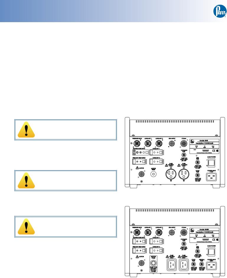
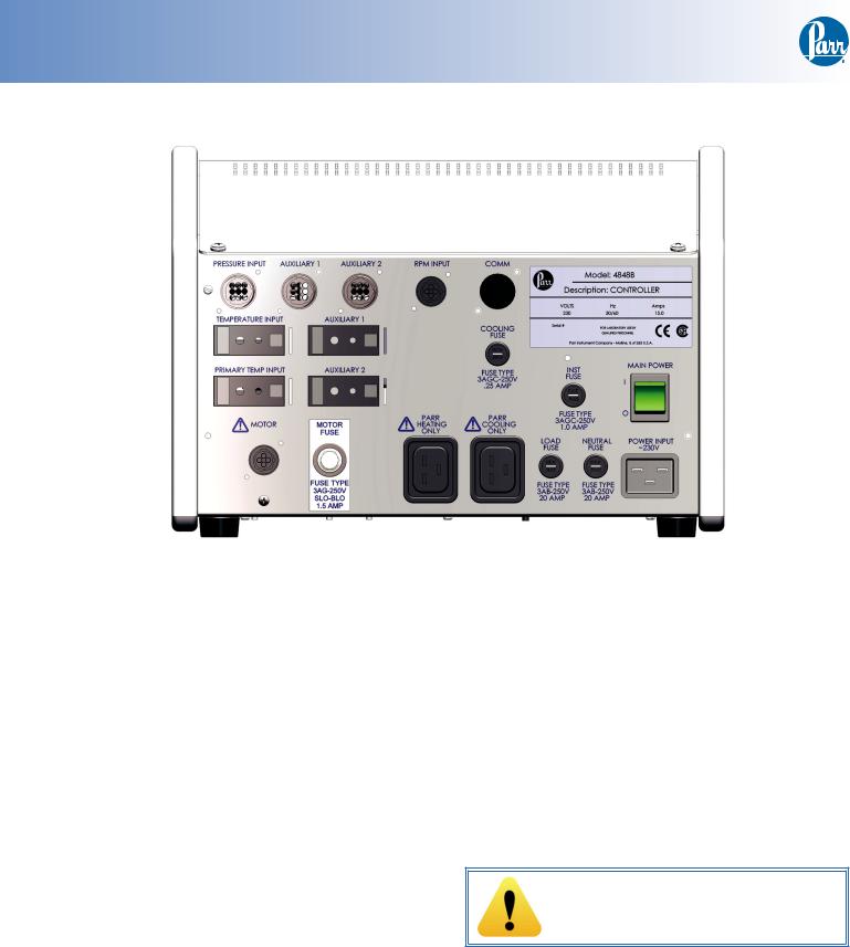
Connections
Labeled connections are provided on the rear panel of the controller.
Parr Cooling Only:
The cooling output connector is to be used only with Parr Instrument Company cooling solenoid valve assemblies supplied with the appropriate cooling power cord.
Parr Heating Only:
The heating output connector is to be used only with Parr Instrument Company heater assemblies supplied with the appropriate heater power cord.
Motor:
Secure the clamp on motor cord to the controller with the provided screw next to the motor socket for safety purposes.
The motor output connector is to be used only with Parr Instrument Company motor assemblies supplied with the appropriate motor power cord. Other appropriate connectors are provided on the rear panel of the controller.
The Primary Temp Input connection is for the PrimaryTemperature Module sensor input.
6 |
P a r r I n s t r u m e n t C o m p a n y |
The Temperature Input connection is for theTemperature Module or ETLM sensor input.
The Pressure Input connection is for the Pressure Module sensor input.
The RPM Input connection is for the RPM Module sensor input.
The Comm connector is for Communication output.
The Auxiliary 1 and Auxiliary 2 input connections are for additional connections and may be used on a number of devices.The 4848B Reactor Controller can be purchased with Auxiliary 1 and/or 2 configured as aTemperature Module Input or a Pressure Module Input.
4848B Rear Panel 115V
4848B Rear Panel 230V
4848B Reactor Controller
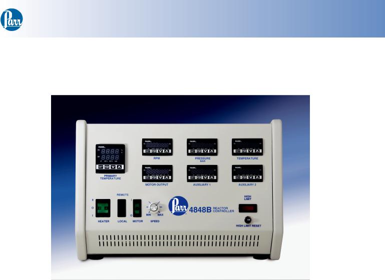
Component Summary
Switches and Indicators
Front Side
4848B Reactor Controller
The Heater Switch is a manual, three-position, illuminated switch which controls the amount of power sent to the heater. In the HIGH (II) position, full power is developed by the heater. In the middle (0) position the heater is off. In the LOW (I) position, a diode is switched into the system to allow only onehalf of the rated voltage to be supplied to the heater. This low setting will be most useful when operating the reactor at temperatures below 175 °C. Power for the heater is supplied through a solid state relay controlled by the temperature control module. The light in the heater switch will glow only when current is flowing to the heater.
The high limit indicator light will glow if the controller receives an indication from any of its sensors that a high temperature or high pressure limit has been reached and the High Limit Reset has opened. When the light comes on, the user must find the source of the problem, correct it, and then manually reset the system using the high limit reset button on the front of the controller.
The Motor Controls consist of an on-off switch and a speed control knob. The speed control knob
should be turned down to a minimum setting before turning on the motor switch to minimize electri-
cal surges within the speed control unit. A speed control know is not included when the reactor is equipped with an air motor for stirring or when the controller is created for use with a non-stirred vessel.
If equipped with a motor control module, there will also be a remote/local switch. When the remote/ local switch is in local mode, the speed control knob will adjust the motor stirring speed. When the remote/local switch is in remote mode, the RPM module will adjust the motor stirring speed. If there is no motor control module installed, the remote/local port will be plugged and the speed control knob is the sole control for the stirring speed.
The Main Power Switch will cut off power to the controller.Take care to position the controller such that the main power switch may be accessed easily
when the controller needs to be disconnected.
w w w . p a r r i n s t . c o m |
7 |
4848B Reactor Controller
Back Side
4848B Reactor Controller
Protective Fuses and Relays
An instrument fuse is mounted on the back panel. This is a Fast-acting, 250VAC, 1.0 amp fuse, intended to protect the temperature control module and any installed display modules.
The motor reset/motor fuse provides overload protection for 0-90VDC motors. This is a re-settable breaker designed to protect the motor if it becomes overloaded. The breaker will have a rating selected to match the motor on the apparatus.
A lighted fuse holder provides protection for 0-180 VDC motors. A light will come on if the motor becomes overloaded and the fuse burns out. The fuse rating will be selected to match the motor on the apparatus.
A load fuse is mounted on the back panel on 115V systems. This fast-acting, 250VAC, 20 amp fuse is intended to protect the controller and prevent electric shock hazard from fault from occurring.
Two load fuses are mounted on the back panel on 230V systems. These are fast-acting, 20 Amps, 250VAC and are intended to protect the controller
and to prevent electric shock hazard from fault from occurring.
Caution!
Unplug unit before servicing. For continued protection against possible hazard, replace fuses with same type and rating of fuse.
8 |
P a r r I n s t r u m e n t C o m p a n y |
Loading...