


 Loading...
Operating Instruction Manual |
591M |
6772
Calorimetric Thermometer
Operating Instruction Manual For models produced after November 2010

6772 Calorimetric Thermometer Instruction Manual |
|
|
|
|
|
TABLE OF CONTENTS |
|
TABLE OF CONTENTS....................................................................................................... |
1-1 |
PREFACE ............................................................................................................................ |
1-1 |
Scope................................................................................................................................ |
1-1 |
Explanation of Symbols .................................................................................................... |
1-2 |
Provisions for Lifting and Carrying................................................................................ |
1-3 |
INSTALLATION ................................................................................................................... |
2-1 |
Power Connection ............................................................................................................ |
2-1 |
Motor Connection ............................................................................................................. |
2-1 |
Thermistor Probe Installation............................................................................................ |
2-2 |
Communication Connection.............................................................................................. |
2-3 |
Printer Connections .......................................................................................................... |
2-3 |
Balance Connections........................................................................................................ |
2-3 |
Mettler 011/012 Interface ............................................................................................ |
2-4 |
Sartorious Interface.................................................................................................... |
2-4 |
Generic Interface ........................................................................................................ |
2-4 |
Bar Code Port................................................................................................................... |
2-4 |
Computer Connections..................................................................................................... |
2-5 |
QUICK START ..................................................................................................................... |
3-1 |
OPERATION ........................................................................................................................ |
4-1 |
Menu System.................................................................................................................... |
4-1 |
Menu Keys........................................................................................................................ |
4-1 |
Control Keys ..................................................................................................................... |
4-1 |
Programming .................................................................................................................... |
4-2 |
Default Settings ................................................................................................................ |
4-2 |
Performing an analysis ..................................................................................................... |
4-2 |
Manual Test Sequencing .............................................................................................. |
4-3 |
Automatic Test Sequencing.......................................................................................... |
4-5 |
MENU DESCRIPTIONS ....................................................................................................... |
5-1 |
Main Menu ........................................................................................................................ |
5-1 |
Calorimeter Operation Menu ............................................................................................ |
5-1 |
Temperature vs. Time Plot ............................................................................................... |
5-2 |
Temperature Plot Setup Menu.......................................................................................... |
5-2 |
Operating Controls Menu.................................................................................................. |
5-3 |
Spike Controls .................................................................................................................. |
5-4 |
Program Information and Control Menu ........................................................................... |
5-5 |
Date & Time Settings:....................................................................................................... |
5-5 |
Calibration Data and Controls Menu................................................................................. |
5-7 |
Thermochemical Corrections Menu................................................................................ |
5-10 |
Standardization Correction...................................................................................... |
5-10 |
Determination Correction ........................................................................................ |
5-11 |
Calculation Factors Menu ............................................................................................... |
5-12 |
Net Heat/Dry Heat Factors ............................................................................................. |
5-13 |
Data Entry Controls Menu .............................................................................................. |
5-13 |
Reporting Controls Menu................................................................................................ |
5-15 |
Communication Controls Menu ...................................................................................... |
5-16 |
File Management Menu .................................................................................................. |
5-17 |
Run Data File Manager................................................................................................... |
5-18 |

6772 Calorimetric Thermometer Instruction Manual |
|
|
|
|
|
Diagnostics Menu ........................................................................................................... |
5-19 |
CALCULATIONS ................................................................................................................. |
6-1 |
Corrections ....................................................................................................................... |
6-1 |
Manual vs. Fixed Corrections ........................................................................................... |
6-2 |
Definitions......................................................................................................................... |
6-3 |
ASTM, ISO and Other Methods........................................................................................ |
6-6 |
Conversion to Other Moisture Bases................................................................................ |
6-7 |
Conversion to Net Heat of Combustion ............................................................................ |
6-7 |
REPORTS ............................................................................................................................ |
7-1 |
MEMORY MANAGEMENT .................................................................................................. |
8-1 |
MAINTENANCE ................................................................................................................... |
9-1 |
TROUBLESHOOTING ....................................................................................................... |
10-1 |
Error List ......................................................................................................................... |
10-1 |
TECHNICAL SERVICE ...................................................................................................... |
11-1 |
Contact Us...................................................................................................................... |
11-1 |
Return for Repair ............................................................................................................ |
11-1 |
PARTS LIST....................................................................................................................... |
12-1 |
Principal Assemblies in 6772 Calorimetric Thermometer ............................................... |
12-1 |
DRAWINGS........................................................................................................................ |
13-1 |
6772 Schematic.............................................................................................................. |
13-1 |
Internal Parts View of 6772 Calorimetric Thermometer.................................................. |
13-2 |
Internal Parts View of 6772 Calorimetric Thermometer.................................................. |
13-3 |
Back Panel of 6772 Calorimetric Thermometer.............................................................. |
13-4 |
TABLES ............................................................................................................................. |
14-1 |
Table 1 – Default Settings .............................................................................................. |
14-1 |
Table 2 – ISO & BSI Method Settings ............................................................................ |
14-3 |

6772 Calorimetric Thermometer Instruction Manual
PREFACE
Scope
This manual contains instructions for installing and operating the Parr 6772 Calorimetric Thermometer with the 1341 Plain Jacket Calorimeter. For ease of use, the manual is divided into 13 chapters.
Installation
Quick Start
Operation
Menu Descriptions
Calculations
Reports
Memory Management
Maintenance
Troubleshooting
Technical Service
Parts Lists
Drawings
Tables
Subsections of these chapters are identified in the Table of Contents.
To assure successful installation and operation, the user must study all instructions carefully before starting to use the Calorimetric Thermometer to obtain an understanding of the capabilities of the equipment and the safety precautions to be observed in the operation.
Additional instructions concerning the installation and operation of various component parts and peripheral items used with the 6772 Calorimetric Thermometer should be made a part of these instructions. Additional instructions for the optional printer are found in the respective printer package and should be made a part of this book.
No. |
Description |
|
201M |
Limited Warranty |
|
204M |
Operating Instructions for the 1341 Oxygen Bomb Calorimeter |
|
205M |
Operating Instructions for the 1108 Oxygen Combustion Bomb |
|
207M |
Analytical Methods for Oxygen Bombs |
|
230M |
Safety in the Operation of Laboratory and Pressure Vessels |
|
483M |
Introduction to Bomb Calorimetry |
|
This manual contains detailed instructions related to oxygen bomb calorimetry, standardization of the Calorimetric Thermometer, combustion techniques, and thermochemical corrections. These are included in this manual to help the user understand how the 6772 handles these functions when used with the Parr 1341 Plain Jacket Calorimeter.
1-1
6772 Calorimetric Thermometer Instruction Manual
Note:
The unit of heat used in this manual is the International Table (IT) calorie, which is equal to 4.1868 absolute joules.
Specific instructions for use of the 6772 with the Solution Calorimeter, Model 6755 are included in manual number 593M. Instructions for using the 6772 Calorimetric Thermometer with the 6725 Semimicro Calorimeter are included in manual number 592M.
Explanation of Symbols
I |
On position |
O |
Off position |
~Alternating Current (AC)
This CAUTION symbol may be present on the Product Instrumentation and literature. If present on the product, the user must consult the appropriate part of the accompanying product literature for more information.
Protective Earth (PE) terminal. Provided for connection of the Protective Earth (green or green/yellow) supply system conductor.
Safety Information
To avoid electrical shock, always:
1.Use a properly grounded electrical outlet of correct voltage and current handling capability.
2.Ensure that the equipment is connected to electrical service according to local national electrical codes. Failure to properly connect may create a fire or shock hazard.
3.For continued protection against possible hazard, replace fuses with same type and rating of fuse.
4.Disconnect from the power supply before maintenance or servicing.
To avoid personal injury:
1.Do not use in the presence of flammable or combustible materials; fire or explosion may result. This device contains components which may ignite such material.
2.Refer servicing to qualified personnel.
1-2

6772 Calorimetric Thermometer Instruction Manual
Intended Usage
If the instrument is used in a manner not specified by Parr Instrument Company, the protection provided by the equipment may be impaired.
General Specifications
Electrical Ratings
115VAC, 1.0 Amp, 50/60 Hz
230VAC, 1.0 Amp, 50/60 Hz
Before connecting the Thermometer to an electrical outlet, the user must be certain that the electrical outlet has an earth ground connection and that the line, load and other characteristics of the installation do not exceed the following limits:
Voltage: Fluctuations in the line voltage should not exceed 10% of the rated nominal voltage shown on the data plate.
Frequency: Calorimeters can be operated from either a 50 or 60 Hertz power supply without affecting their operation or calibration.
Current: The total current drawn should not exceed the rating shown on the data plate on the calorimeter by more than 10 percent.
Environmental Conditions
This apparatus is to be used indoors.
Operating: |
15 ºC to 30 ºC; maximum relative humidity of 80% non-condensing. |
|
Installation Category II (overvoltage) in accordance with IEC 664. |
|
Pollution degree 2 in accordance with IEC 664. |
|
Altitude Limit: 2,000 meters. |
Storage: |
-25 ºC and 65 ºC; 10% to 85% relative humidity. |
Provisions for Lifting and Carrying
Before moving the instrument, disconnect all connections from the rear of the apparatus. Lift the instrument by grabbing underneath each corner.
Periodic cleaning may be performed on the exterior surfaces of the instrument with a lightly dampened cloth containing mild soap solution. All power should be disconnected when cleaning the instrument. There are no user serviceable parts inside the product other than what is specifically called out and discussed in this manual. Advanced troubleshooting instructions beyond the scope of this manual can be obtained by calling Parr Instrument Company in order to determine which part(s) may be replaced or serviced.
Specifications
Probe type |
Thermistor |
Thermometer range |
10-50 °C |
Resolution |
0.0001 °C |
Absolute accuracy |
|
without calibration |
+/- 0.100 °C |
with calibration |
+/- 0.0500 °C |
Repeatability, |
|
single point |
+/- 0.002 °C |
Linearity, 10 °C span |
+/- 0.002 °C |
Communications port |
Ethernet |
Data logging capacity |
1MB (~10000 points) |
1-3

6772 Calorimetric Thermometer Instruction Manual
INSTALLATION
Power Connection
Plug the power line into any grounded outlet providing proper voltage that matches the specification on the nameplate of the Calorimetric Thermometer. The thermometer will draw approximately 100 watts of power. Grounding is very important not only as a safety measure, but also to ensure satisfactory controller performance. If there is any question about the reliability of the ground connection through the power cord, run a separate earth ground wire to the controller chassis.
Turn the power switch to the on position. After a short time, the Parr logo will appear on the LCD display followed by a running description of the instrument boot sequence. When the boot sequence is complete, the 6772 Calorimetric Thermometer Main Menu is displayed.
Motor Connection
Disconnect power before connecting a motor to the Calorimetric Thermometer. Remove 493E Plug with 3280HC Retainer and attach the motor cord to the rear of the calorimeter case using the mounting screws provided for safety purposes.
Figure 1
6772 Calorimetric Thermometer Back Panel
 493E Plug with 3280HC Retainer installed to insulate from live circuits when no motor is attached.
2-1
6772 Calorimetric Thermometer Instruction Manual
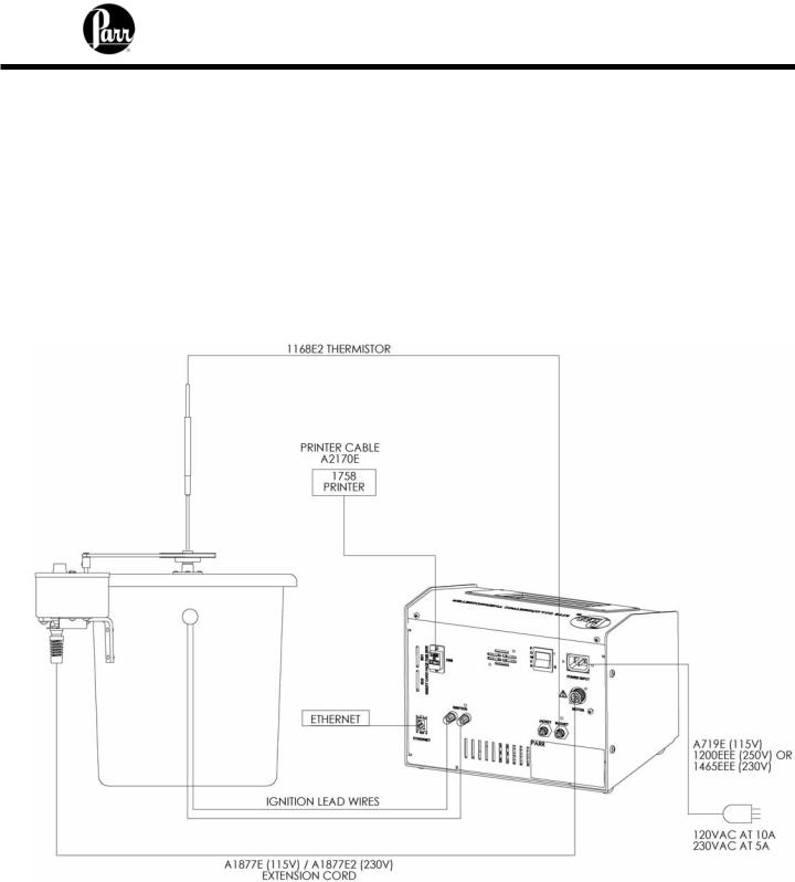
Thermistor Probe Installation
Connections for two thermistor probes are located on the back of the 6772 Calorimetric Thermometer. If only one probe is to be used, connect it to the “bucket” connection. The 6772 Calorimetric Thermometer includes an ignition unit for automatically firing the bomb in the 1341 calorimeter. The ignition leads to the thermometer need to be connected to the red and black terminals marked “Ignition” on the back of the thermometer to take advantage of this feature. The thermistor probe should be set so the bottom tip is 6 inches below the underside of the calorimeter cover. Connect the A1877E (2) extension cord from the motor to the 6772.
Figure 2
Electrical Hookup of 6772 Calorimetric Thermometer to 1341 Calorimeter
2-2

6772 Calorimetric Thermometer Instruction Manual
Communication Connection
There is a USB connection on the rear of the 6772 to facilitate printer and balance connections.
The 6772 will also allow the user to specify the IP addresses of one or more Balance Interface devices on the network by selecting the Network Data Device menu in the Communications Controls menu. Balance Interface devices are polled from device 1 to 15 for sample and / or spike weights when the weight entry mode is set to Network.
Printer Connections
The printer type setting is on the Communication Controls Menu. The default parameters for the 6772 Calorimetric Thermometer are set up for use with the Parr 1758 Printer.
Balance Connections
The 6772 Calorimetric Thermometer supports input from the multiple balance types. Additionally, a generic input driver is provided for communications with balances that do not conform to the eight supported protocols. A new feature supported by all balance input drivers is the ability to change the expected number of characters in the data field. The number of data characters indicated for each of the drivers, below, are default values. This feature virtually eliminates the need for balance input drivers to be re-written in the event the balance manufacturer elects to alter the output string of a balance when new models are introduced.
2-3

6772 Calorimetric Thermometer Instruction Manual
The format of an unknown balance can be determined by logging the balance output to the printer attached to the Calorimetric Thermometer. Those protocols which send a command string to the balance will do so while logging is active. In order for the logging to produce meaningful results, the cable connecting the balance to the balance input port of the Calorimetric Thermometer must be correctly wired or configured. In addition, the specifics of the data frame, such as the baud rate, # of data bits, parity, # of stop bits and handshaking (if used) must be the same for both the balance and the Calorimetric Thermometer.
Mettler 011/012 Interface
The ID field must contain “S_” to indicate a stable mass. The data field contains the current mass, right justified, with a decimal point. The balance should be configured to send continuously.
Sartorious Interface
The polarity field must contain either a “+” or a space. Leading zeros in the data field are blanked, except for the one to the left of the decimal point. The stability field must contain “g_” for the Calorimetric Thermometer to accept a mass. The balance should be configured to transmit data upon receipt of the following command string:
[ESC] P [CR] [LF]
Field |
Length |
ID |
2 |
space |
1 |
data |
9 |
space |
1 |
g |
1 |
CR |
1 |
LF |
1 |
Field |
Length |
polarity |
1 |
space |
1 |
data |
8 |
space |
1 |
stability |
2 |
CR |
1 |
LF |
1 |
Note:
The automatic data output option should not be used.
The Calorimetric Thermometer will send this command string once every few seconds after the ENTER key has been pressed during a mass entry sequence. The ENTER key should only be pressed when the mass reading is stable.
Generic Interface |
Field |
Length |
The data field should consist of 9 |
data |
8 |
numeric characters (0 through 9, +, - |
CR |
1 |
and space) terminated with a carriage return (CR). Leading zeros may be
blanked as spaces and are counted. Non-numeric characters are ignored and will reset the input buffer if the data field has not been filled. Any characters received after filling the data field and before the carriage return are ignored.
Bar Code Port
The use of barcodes in the laboratory has become a highly accurate, rapid and inexpensive way to identify samples. When purchasing this feature, the user must supply Parr with the MAC address of the calorimeter (found in the Software & Hardware Info menu screen). This
2-4
6772 Calorimetric Thermometer Instruction Manual
allows Parr to activate the feature key. In order to enable the calorimeter to use the bar code feature, the feature key needs to be entered into the instrument. Select the “Program Information and Control” key from the Main Menu. Next, select “Feature Key” and enter the feature key purchased from Parr Instrument Company into the instrument by using the touchpad. Pressing the key labeled “ABC” allows the user to switch from upper case letters, to lower case letters and finally to numerals. A CD containing all the necessary documentation and setup information for using both the scanner and the printer is provided at the time of purchase. A PC based program used for printing bar coded labels is also provided on this CD.
Computer Connections
If the 6772 Calorimetric Thermometer is to be connected to a computer, the Ethernet connection should be used. Calorimetric Thermometer test data can be transferred to an Ethernet network connected computer using the FTP File Transfer Protocol. First, you must know the IP address of the network-connected Calorimetric Thermometer. The network DHCP (Dynamic Host Configuration Protocol) server provides this address shortly after the Calorimetric Thermometer is turned on. The address can be seen on the Software & Hardware Info” screen,
under Program Info and Control Menu; see the example screenshot. Users who don’t have a network infrastructure can create a simple network by connecting a router with DHCP server capability to the Calorimetric Thermometer using an ordinary CAT 5 network cable. The Calorimetric Thermometer should be connected to LAN side of the router. The PC in turn is also connected to the LAN side of the router using a similar CAT 5 cable. A D-Link 614+ router is recommended for this purpose. For this router, operated without a WAN connection, the primary DNS address of the router (WAN setup) must be set to the IP address of the router found on the LAN setup page. Other routers behave differently in the absence of a WAN connection. Providing an active upstream connection to the WAN port of most routers generally minimizes the use of any obscure setup configurations. An FTP enabled web browser can be used to access stored test data. The URL is of the following form:
ftp://root:rootroot@192.168.0.125/../flash/data/
In this case, 192.168.0.125 is the IP address of the Calorimetric Thermometer.
2-5

6772 Calorimetric Thermometer Instruction Manual
The following screenshot illustrates the contents of the Calorimetric Thermometer data directory as presented by a web browser.
You can drag and drop or copy and paste test data files (with the csv suffix) from the web browser window to any convenient folder or directory on the PC.
2-6
6772 Calorimetric Thermometer Instruction Manual
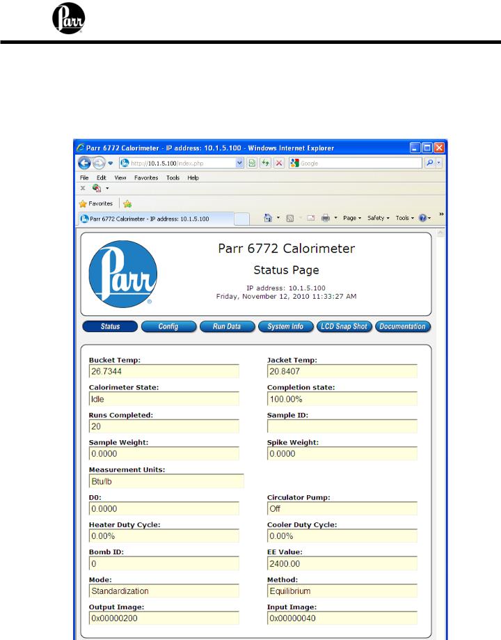
The Calorimetric Thermometer offers a web server service. Test reports can be viewed with a web browser using a URL of the following form.
http://192.168.0.125
Where 192.168.0.125 is the IP address of the Calorimetric Thermometer. The following screenshot illustrates the Calorimetric Thermometer status page.
2-7
6772 Calorimetric Thermometer Instruction Manual
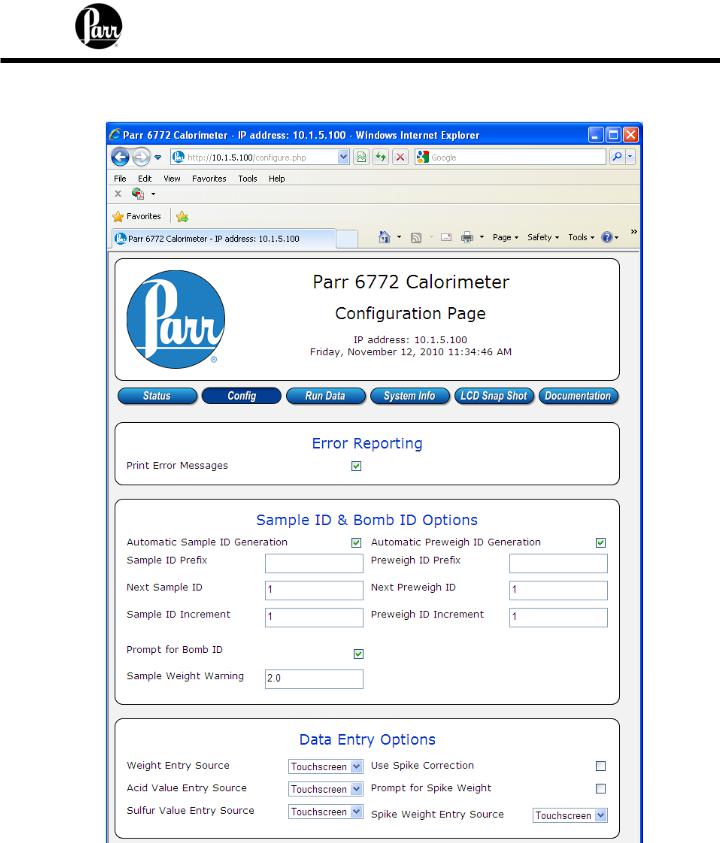
Clicking on the Config tab displays some of the configuration options available in the 6772. Changes made on this page will change the settings in the 6772.
2-8
6772 Calorimetric Thermometer Instruction Manual
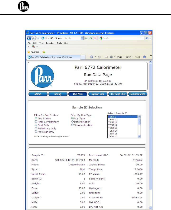
Clicking on the Run Data tab displays a list of reports currently in the instrument memory. Clicking on any given report will provide a display similar to the following:
2-9

6772 Calorimetric Thermometer Instruction Manual
Clicking on System Info will bring up the Software and Hardware Info screen from the 6772.
2-10

6772 Calorimetric Thermometer Instruction Manual
Clicking on the LCD Snapshot Page will bring up an image of the current display on the 6772. Note that this is a picture only. To operate the 6772 from a PC a Remote Feature Key must be installed. Please contact Parr Instrument Company for more details.
2-11
6772 Calorimetric Thermometer Instruction Manual
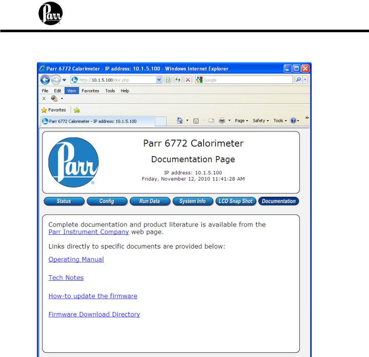
Clicking on Documentation will provide links to the manual and other helpful documents. Note: a connection to the Internet is required to access the documentation.
2-12

6772 Calorimetric Thermometer Instruction Manual
QUICK START
The basic operating instructions for the 1341 Calorimeter are found in Operating Instructions Manual No. 204M. Detailed instructions for preparing the sample and charging the 1108 Oxygen Bomb are given in the operating instructions, manual number 205M. Follow these instructions carefully, giving particular attention to the precautions to be observed in charging and handling the bomb. The default values of the 6772 are designed to operate with the 1341 Plain Jacket calorimeter.
1.Allow at least 20 minutes for the thermometer to warm up. The bomb parts should be wetted and then dried in the manner used at the conclusion of a test. This serves to wet all sealing parts as well as leaving the bomb with the same amount of residual water which will exist in all subsequent testing.
2.Turn on the stirrer motor switch on the 1341 Calorimeter.
3.Prepare and weigh the sample to 0.0001g. Charge the oxygen bomb as described in manual 205M. Using an additional bomb and bucket can increase the throughput of the 1341 Calorimeter. With this arrangement, the calorimeter can operate almost continuously since the operator will be able to empty a bomb and recharge it while a run is in progress. A bomb and bucket for the next run will be ready to go into the calorimeter as soon as it is opened. Each bomb and bucket combination will have to be standardized separately and the proper energy equivalent for each set must be used when calculating the heat of combustion.
4.Fill the calorimeter bucket by first taring the dry bucket on a solution or trip balance; then add 2000 (+/- 0.5) grams of water. Distilled water is preferred, but demineralized or tap water containing less than 250 ppm of dissolved solids is satisfactory. The bucket water temperature should be at or slightly below (1-2 degrees) the room temperature. It is not necessary to use exactly 2000 grams, but the amount selected must be duplicated within +/- 0.5 gram for each run. Instead of weighing the bucket, it can be filled from an automatic pipet, or from any other volumetric device if the repeatability of the filling system is within +/- 0.5 ml.
5.Set the bucket in the calorimeter. Attach the lifting handle to the two holes in the side of the screw cap and partially lower the bomb in the water. Handle the bomb carefully during this operation so that the sample will not be disturbed. Push the two ignition lead wires into the terminal sockets on the bomb head. Orient the wires away from the stirrer shaft so they do not become tangled in the stirring mechanism. Lower the bomb completely into the water with its feet spanning the circular boss in the bottom of the bucket. Remove the lifting handle and shake any drops of water back into the bucket and check for gas bubbles.
6.Close the calorimeter cover. This lowers the stirrer and thermistor probe into the bucket.
7.Select determination or standardization as appropriate on the Calorimeter Operation page, by toggling the operating mode key. The calorimeter will now prompt the operator for Bomb
3-1

6772 Calorimetric Thermometer Instruction Manual
ID number, sample ID number, sample weight and spike weight in accordance with the instructions set into the operating controls page.
8.The thermometer will now take over and conduct the test. During the time it is establishing the initial equilibrium, it will display PREPERIOD on the status bar. Just before it fires the bomb, it will sound a series of short beeps to warn the user to move away from the calorimeter. Once the bomb has been fired, the status bar will display POSTPERIOD. The calorimeter will check to make certain that a temperature rise occurs and will then look for the final equilibrium conditions to be met. If it fails to meet either the initial or final equilibrium conditions, or if it fails to detect a temperature rise within the allotted time, the thermometer will terminate the test and advise the user of the error.
9.At the conclusion of the test, the thermometer will signal the user.
10.Open the cover and remove the bomb and bucket. Remove the bomb from the bucket and open the knurled valve knob on the bomb head to release the residual gas pressure before attempting to remove the cap. This release should proceed slowly over a period of not less than one minute to avoid entrainment losses. After all pressure has been released, unscrew the cap; lift the head out of the cylinder and examine the interior of the bomb for soot or other evidence of incomplete combustion. If such evidence is found, the test will have to be discarded. Otherwise, wash all interior surfaces of the bomb, including the head, with a jet of distilled water and collect the washings in a beaker.
11.Remove all unburned pieces of fuse wire from the bomb electrodes; straighten and measure the combined length in centimeters. Subtract this length from the initial length of 10 centimeters. Multiply the burned length by 2.3 calories per cm (for Parr 45C10 Fuse Wire) to obtain the fuse correction. The scale on the fuse wire card can be used to obtain this value in calories by laying the unburned pieces from right to the left on the card. (Alternatively a fixed correction of 15 calories may be entered into the calorimeter in the Thermochemical Corrections menu.)
12.Titrate the bomb washings with a standard sodium carbonate solution using methyl orange, red or purple indicator. A 0.0709N sodium carbonate solution is recommended for this titration to simplify the calculation. This is prepared by dissolving 3.76 grams of
Na2CO3 in the water and diluting to one liter. NaOH or KOH solutions of the same normality may be used.
13.Analyze the bomb washings to determine the sulfur content of the sample if it exceeds 0.1%. Methods for determining sulfur are discussed in Operating Instructions No. 207M.
14.At the end of the testing period, turn OFF the stirrer motor and the thermometer at the power switch.
3-2
6772 Calorimetric Thermometer Instruction Manual
OPERATION
Menu System
All configurations and operations are handled by a menu-driven system operated from the bright touch screen display. The settings and controls are organized into ten main sections as displayed on the MAIN MENU.
Note:
Keys with a “double box” in the upper left hand corner lead to sub-menus.
Menu Keys
The controls that change the data field information in the menus will be one of the following:
1.Toggles. These data fields contain ON/OFF or YES/NO choices. Simply touching the key on the screen toggles the choice to the other option. The current setting is displayed in the lower right corner of the key.
2.Option Selection. These data fields contain a list of options. Touching the key on the screen steps the user through the available choices. The current setting is displayed in the lower right corner of the key.
3.Value Entry Fields. These data fields are used to enter data into the Calorimetric Thermometer. Touching the key on the screen brings up a sub-menu with a key pad or similar screen for entering the required value. Some keys lead to multiple choices. Always clear the current value before entering a new value. Once entered the screen will return to the previous menu and the new value will be displayed in the lower right corner of the key.
4.Data Displays. Most of these keys display values that have been calculated by the Calorimetric Thermometer and are informational only. Certain ones can be overridden by the user entering a desired value through a sub-menu. The value is displayed in the lower right corner of the key.
Note:
Some keys will respond with an opportunity for the user to confirm the specified action to minimize accidental disruptions to the program and/or stored data.
Control Keys
There are six control keys which will appear in the right column of the primary displays. These keys are unavailable when they are gray instead of white.
1.Escape. This key is used to go up one level in the menu structure.
2.Main Menu. This key is used to return to the main menu touch screen from anywhere in the menu structure.
3.Start. This key is used to start a Calorimetric Thermometer test.
4-1
Loading...