


396M
4560
Mini BenchTop Reactors
Operating Instruction Manual

Mini Bench Top Reactors
Table of Contents
Preface
Scope — 3
Related Instructions — 3
Safety Information — 3
General Specifications — 3
Electrical Ratings— 3
Explanation of Symbols — 4
Environmental Conditions — 4
Provisions for Lifting and Carrying — 4
Intended Usage — 4
Cleaning & Maintenance — 4
User’s Responsibility — 5
Unpack Carefully — 5
Fixed Head or Removable Head Vessel Design — 6
Flat PTFE Gasket or Self Sealing O-ring Closure — 6
Installation
Pressure andTemperature Limits — 7
Assemble the Reactor — 8
Identify the Valves
Gas Inlet Valve — 9
Gas Release Valve — 9
Liquid Sampling Valve — 9
Other Vessel Head Fittings
Safety Rupture Disc — 10
Type JThermocouple — 10
Pressure Gage — 10
Heaters — 10
How to Use the Vessel
Removable Vessels — 11
Fixed Head Vessels — 11
Air Motor — 13
Explosion Proof Operation — 14
Periodic Pressure Tests — 15
Accessories
Liners — 15
Spare Parts Kit — 15
General Maintenance Notes — 16
4560 Series Reaction Vessel Parts List
Standard Vessel Fittings — 17
HighTemperature Vessel Fittings — 22
Overarm Parts List — 25
Figures
Fixed Head with O-ring — 6 Moveable Head with Flat Gasket — 6
Removable Head Vessel (StandardTemperature) — 19 Air Motor Option — 13
Vessel Closure and Standard Internal Parts — 17 4561 Gas Entrainment Assembly — 20
4563 Gas Entrainment Assembly — 20
Mini Head External Fittings & Parts List — 21
Vessel Closure and Standard Internal Parts — 22
Overarm Diagram — 25
Bomb Support Stand with Fixed Head and 1/8 hp
Stirrer Drive Motor — 26
Bomb Support Stand with Moveable Vessel and 1/4 hp Stirrer Drive Motor — 27
Customer Service
Questions concerning the installation or operation of this instrument can be answered by the Parr Customer Service Department:
1-309-762-7716 • 1-800-872-7720 • Fax: 1-309-762-9453
E-mail: parr@parrinst.com • http://www.parrinst.com
2 |
P a r r I n s t r u m e n t C o m p a n y |
Preface
Scope
These instructions describe the installation, operation and maintenance of Parr Series 4560 Mini BenchTop Reactors offered in sizes from 100 mL to 600 mL. They cover the basic steps to be followed for installing these reactors and describe the function of all standard components. They cover the basic steps to be followed when installing these reactors and describe the function of all standard components. They are intended to be used in conjunction with several related instruction sheets listed on the previous page. This information describes several components that are common to most Parr pressure reaction equipment, and includes safety precautions and other related information applicable to all reaction laboratories. The users should study all of these instructions carefully before starting to use these vessels so that they will fully understand the capabilities and limitations of the equipment.
Related Instructions
The following Parr publications are also included to further your understanding of this instrument and its component parts:
No. Description
201M Limited Warranty
230M Safety Precautions to be observed when operating Pressure Reaction Equipment
231M Operating Instructions for Parr Safety Rupture Discs
234M Operating and Maintenance Instructions
for Parr Magnetic Drives
323M Operating Instructions for Parr Pressure Relief Valves
548M Operating Instructions for 4848 Reactor Controllers
F0042 Health & Safety Assurance Certification
Safety Information
To avoid electrical shock, always:
Use a properly grounded electrical outlet of correct voltage and current handling capacity.
Disconnect from power supply before servicing. The power supply cord of the equipment is the main disconnect device.
Mini Bench Top Reactors
To avoid personal injury:
Do not use in the presence of flammable or combustible materials; fire or explosion may result. This device contains components which may ignite such materials. Refer servicing to qualified personnel.
General Specifications
Electrical Ratings
Controller ratings are found in the Operating Instructions for the controller supplied with your reactor.
Before connecting a controller to an electrical outlet, the user must be certain that the electrical outlet has an earth ground connection and that the line, load and other characteristics of the installation do not exceed the following limits:
Voltage: Fluctuations in the line voltage should not exceed 10% of the rated nominal voltage shown on the data plate.
Frequency: Controllers can be operated from either a 50 or 60 Hertz power supply without affecting their operation or calibration.
Current:The total current drawn should not exceed the rating shown on the data plate on the controller by more than 10 percent.
Inductive Loads: Inductive loads must be limited to
750 watts (1 hp) at 115 volts, or to 1100 watts (1-1/2 hp) at 230 volts. Do not connect these controllers to the primary (input) side of an auto-transformer (Variac, Powerstat or the like). The heavy inductive load on the primary side of such transformers will destroy the relay. The secondary (output) side of an auto-transformer can be carried through the relay if this circuit is isolated from the controller. A separate, full-voltage connection must then be made to operate the temperature controller and to actuate the relay.
Thermocouple: Unless otherwise specified, all
Series 4848 Controllers operate with aType J (ironconstantan) thermocouple. The total resistance of the thermocouple and the lead wires should not exceed 20 ohms. If the resistance of the thermocouple circuit is higher, it will reduce the sensitivity of the control system.
w w w . p a r r i n s t . c o m |
3 |

Mini Bench Top Reactors
Explanation of Symbols
II |
On position, full power heater switch |
|
|
I |
On position, half power heater switch |
|
|
O |
Off Position |
|
|
~ |
Alternating Current (AC) |
|
|
|
This CAUTION symbol may be present on the Product Instrumentation |
|
and literature. If present on the product, the user must consult the ap- |
|
propriate part of the accompanying product literature for more infor- |
|
mation. |
|
This CAUTION symbol indicates that the surface may be hot. |
|
|
|
Protective Earth (PE) terminal. Provided for connection of the Protec- |
|
tive Earth (green or green/yellow) supply system conductor. |
|
|
Environmental Conditions
This instrument is intended to be used indoors.
Caution!
Do not use in hazardous atmospheres.
Operating: 15 ºC to 40 ºC; maximum relative humidity of 80% non-condensing. Installation Category II (over voltage) in accordance with IEC 664.
Pollution degree 2 in accordance with IEC 664.
Altitude Limit: 2,000 meters.
Storage: -25 °C and 65 °C; 10% to 85% relative humidity.
Provisions for Lifting and Carrying
Before moving ensure all cables are disconnected. Use proper and safe lifting techniques when installing or moving the 4560 Reactor and/or its components.
Intended Usage
This system has been designed for use as a high pressure reactor system. It has been designed, built, and tested to strict physical and electrical standards.
However, it is the user’s responsibility to install and operate it in conformance with local pressure and electrical codes.
If this equipment is used in a manner beyond its intended usage, the protection provided by the equipment may be impaired.
Cleaning & Maintenance
Periodic cleaning may be performed on the exterior surfaces of the controller with a lightly dampened cloth containing mild soap solution. All power should be disconnected and the power cord should be unplugged when cleaning the instrument.
There are no user serviceable parts inside the product other than what is specifically called out and discussed in this manual. Advanced troubleshooting instructions beyond the scope of this manual can be obtained by calling Parr Instrument Company
in order to determine which part(s) may need to be replaced or serviced.
Ensure that any hot surfaces have had adequate time to cool before cleaning or maintaining the reactor and/or its components.
4 |
P a r r I n s t r u m e n t C o m p a n y |

User’s Responsibility
All Parr reactors and pressure vessels are designed and manufactured with great care to assure safe operation when used within their prescribed temperature and pressure limits.
But . . . the basic responsibility for safety when using this equipment rests entirely with the user; who must:
1.Select a reactor or pressure vessel that has the capability, pressure rating, corrosion resistance and design features that are suitable for its intended use. Parr engineers will be glad to discuss available equipment and material options with prospective users, but the final responsibility for selecting a reactor or pressure vessel that will perform to the user’s satisfaction in any particular reaction or test must rest with the user
– not with Parr.
In exercising the responsibility for the selection of pressure equipment, the prospective user is often faced with a choice between over-or underdesigned equipment. The hazards introduced by under-designed pressure vessels are readily apparent, but the penalties that must be paid for over-designed apparatus are often overlooked. Recognizing these criteria, Parr reactors and pressure vessels are offered in several different styles, each designed for convenient use in daily operation within certain temperature and pressure limits, using gaskets, closures and other elements carefully selected for safe operation within the limits specified for that design. But in order to preserve the validity of these designs, all temperature and pressure limits must be observed, and no attempt should be made to increase these limits by making alterations or by substituting components which are not recommended by Parr Instrument Company.
Mini Bench Top Reactors
2.Install and operate the equipment within a suitable barricade, if required, with appropriate safety accessories and in full compliance with local safety codes and rules.
All standard Parr pressure vessels are provided with either suitable relief device or a means to attach one (typically in the form of a plugged opening). When a pressure vessel is delivered without a pressure venting device, it is the customer’s responsibility to provide pressure relief in order to protect the operator and the equipment from destructive high pressures. If you need more information or need help in selecting a proper relief device, please contact Parr Instrument Company.
3.Establish training procedures to ensure that any person handling the equipment knows how to use it properly.
4.Maintain the equipment in good condition and establish procedures for periodic testing to be sure the vessel remains structurally sound.
Unpack Carefully
Unpack the equipment carefully and check all the parts against the, packing list. If shipping damage is discovered, report it immediately to the delivering carriers. The vessel, motor, heater, and temperature controller may be packed separately for convenience in shipping, but these parts are easily reassembled. Examine the components closely for any loose parts or shipping damage and be sure to check all layers of packing materials thoroughly so as not to overlook any parts which might otherwise be discarded.
w w w . p a r r i n s t . c o m |
5 |

Mini Bench Top Reactors
Parr Series 4560 Mini Reactors are furnished with two structural options in addition to the size, pressure range, stirrer motor, controller and similar options. These are:
Fixed Head or Removable Head Vessel Design
In the fixed head design, the head of the vessel may remain fixed in the reactor support stand. All attachments to the head, gas and liquid feed and discharge lines, cooling water, vapor take-off and condenser, thermocouple, and any electrical leads can remain permanently in place. The reactor is opened by removing the cover clamp sections and lowering the cylinder away from the head.
In the removable vessel design, the entire vessel must be removed from the support stand for charging, product recovery, and cleaning.
There is no difference in the pressure or temperature limits or basic operating instructions based upon the fixed head or movable vessel options. There are differences in the design of the stand components which adapt the vessels to the support system.
Flat PTFE Gasket or Self Sealing O-ring Closure
The flat gasket is held in a recess in the vessel head and a machine pilot on the cylinder closes the recess to completely contain the gasket. The split ring closure used with this gasket has six cap screws which must be tightened to develop the loading on the gasket.
The self sealing design features an O-ring retained in a groove on the vessel head. This design is self sealing and the split ring used with this sealing system does not require nor have the cap screws used with the flat gasket.
Maximum temperatures of a given system are dependant upon the material of construction and type of seal. Other accessories may limit operating temperature.The fl at PTFE gasket can be used to operating temperatures as high as 350 °C.The flat flexible graphite gasket can be used to operating temperatures as high as 500 °C.The maximum temperature of the vessels equipped with O-ring seals depends upon the material used for the O-ring.The most common material is a fl uoroelastomer (FKM) which has a 225 °C maximum operating temperature limit.
|
Fixed Head with O-ring |
Moveable Head with Flat Gasket |
6 |
P a r r I n s t r u m e n t C o m p a n y |
|
Installation
Pressure andTemperature Limits
The working pressure and temperature at which any reactor or pressure vessel can be used will depend upon the design of the vessel and the materials used in its construction. Since all materials lose strength at elevated temperatures, any pressure rating must be stated in terms of the temperature at which it applies.The standard material of construction for Parr Instrument Company isType 316 Stainless Steel.
Limits for vessels made of other materials and for other operating temperatures can be obtained from
Parr Customer Service. No attempt should be made to increase these limits by making alterations or by substituting components that are not recommended by the Parr Instrument Company. It must also be understood that lower pressure and temperature limits may be required for modified reactors and for vessels made of special alloys.
Limits for vessels will be determined by the physical characteristics of the vessel material and will be prescribed on an individual basis.
The maximum working pressure and temperature for any vessel is governed by the design of the vessel and the strength of the material from which it is constructed.There is also a close relationship between working pressure and temperature since the strength of any material will normally fall off as the temperature is increased.Temperature and pressure limits are also affected by the physical
properties and temperature limits of the gaskets and seals used in the vessel, and by any valves, gages or other fittings attached to the vessel.The safe operating pressure of any system can be no higher than that of its lowest rated component.
All Parr reactors show the maximum safe operating pressure and temperature imprinted on the cylinder.
An accompanied restricted operating limit tag and/ or supplemental manual is given when a component of the system limits the operation below the imprinted valves.
Mini Bench Top Reactors
Working temperatures up to 225 °C are permissible in Mini Reactors equipped with fluoroelastomer
(FKM) O-ring seals. The higher the operating temperature above 200 °C, the shorter the life of the O- ring will be. Perfl uoroelastomer (FFKM) O-ring seals have a broad chemical resistance and can be used to temperatures up to 300 °C. Unfortunately they are very expensive and will generally be reserved for unique applications. Ethylene-propylene (EP) O-rings can be used to 170 °C and are recommended for applications such as ethers, ammonia and amines which will rapidly destroy fluoroelastomer
O-rings.
Pressure Vessel andTemperature Limits
In the standard pressure and temperature setup, the system must not exceed the following:
Vessel |
Maximum |
Maximum |
Material |
Pressure |
Temperature |
|
|
|
T316SS |
3000 psig (200 bar) |
350 °C PTFE |
Flat Gasket |
||
T316SS |
3000 psig (200 bar) |
225 °C FKM |
|
|
O-Ring |
T316SS |
3000 psig (200 bar) |
300 °C FFKM |
O-Ring |
||
|
|
|
In the high pressure/high temperature setup, the system must not exceed the following:
Vessel |
Maximum |
Maximum |
Material |
Pressure |
Temperature |
T316SS (HT) |
2000 psig (138 bar) |
500 °C Flexible |
|
|
Graphite Flat |
|
|
Gasket |
w w w . p a r r i n s t . c o m |
7 |
Mini Bench Top Reactors
Assemble the Reactor
These reactors require at least 10 sq. ft. of workspace in a well-ventilated area with convenient access to an electric outlet, running water, air and a drain.
1. Set the stand in the workspace.
Bolt the stand to the bench top using the holes in the base plate.
2.The support and heater are shipped fully assembled. The heater raises and lowers on its support rod to permit the vessel or cylinder to be removed. Lower the heater, open the hinged retainer on the front of the support and slide the vessel into its support. Fixed head vessels have a square lip which fits into a matching groove in the support plate. Removable vessels are supported by the split rings which rest on the support plate adapter. The stirrer drive connector lifts by rotating and lifting the knob above the belt guard. The universal joint contains a cross pin that slips into the groove on top of the magnetic drive.There is a bracket at the back of the area where the split ring rests. The thumb screw on the drop band which encircles the split ring closure should fit into the slot on this bracket. This will keep the vessel from rotating when stirring viscous reactions. It may be necessary to reposition the drop band if the gage does not face forward when the thumb screw is in the slot.
3.Set theTemperature Controller near the reactor, leaving a space of at least six inches between the controller and the base of the reactor so that the controller will not be unduly affected by radiant heat. Connect the reactor to the controller using information contained in its Instruction
Manual 548M or follow the steps below.
Labeled connections are provided on the rear panel of the controller.
Parr Cooling Only:
The Parr Cooling output connector is to be used only with Parr Instrument Company cooling solenoid valve assemblies supplied with the appropriate cooling power cord.
8 |
P a r r I n s t r u m e n t C o m p a n y |
Parr Heating Only:
The Parr Heating output connector is to be used only with Parr Instrument Company heater assemblies supplied with the appropriate heater power cord.
Note: Do not make connections to a Variac, Powerstat or the like to attempt to control the heating output. The heavy inductive load on the primary side of such devices can destroy the internal sold state relay located in the 4848 controller.
Motor:
Secure the clamp on motor cord to the controller with the provided screw next to the motor socket for safety purposes.
The Motor output connector is to be used only with Parr Instrument Company motor assemblies supplied with the appropriate motor power cord.
4.Connect the heater cord from the heater into the heater socket on the rear panel of the Series
4848 Reactor Controller.
5.Plug the motor cord into the motor socket on the rear of the controller.
Secure the clamp on the motor cord with the provided screw next to the motor socket for safety purposes.
6.Connect the thermocouple and extension wire to both the thermocouple and to the controller in the “PrimaryTemp Input” position on the rear panel. Insert the thermocouple in the thermowell.
7.Connect leads from accessory packages such as tachometer, pressure transducer and high temp cut-off to the designated positions on the back panel of the 4848 Controller.
8.Connect cooling water to the magnetic drive.
See Instruction Manual No. 234M.
9.Connect tubing to the rupture disc outlet and run to a safely vented area. See Instruction Manual 231M.
Mini Bench Top Reactors
10.Note the voltage and amperage requirement stamped on the controller data plate, and then plug the power cord into an appropriate outlet. Power for these reactors should be drawn from a grounded outlet capable of carrying up to the full current rating of the reactor.
11.If an electric stirrer motor is supplied, turn the speed control knob fully counterclockwise on the Reactor Controller, turn on the motor switch and slightly increase the speed for a short run to check the stirrer drive system but do not turn on the heater, put heater toggle switch in center position (OFF).There must always be a vessel in the heater when it is turned on, and the vessel and heater sizes must match. If the heater is operated without proper size vessel in contact with the heater, the heater may overheat and fail.
Identify the Valves
Gas Inlet Valve
The gas inlet valve is easily identified when the vessel is open by noting that it is connected to a dip tube which extends to a point near the bottom of the cylinder. With this arrangement, incoming gas is always introduced below the surface of the liquid. This valve includes a coupling with an “A” socket connection for attachment of the pressure hose.
Gas Release Valve
The gas release valve is typically connected to a side opening on the gage adapter. Gas released from this valve will be drawn from the top of the reactor.
Liquid Sampling Valve
The liquid sampling valve is attached to the same fitting as the gas inlet valve and connected to the same dip tube.This provides the operator with a means for clearing the dip tube to be sure that any sample taken during a run will be representative of the charge. This can be done by opening the upper gas inlet valve momentarily to allow the inlet gas to force any liquid in the dip tube back into the reactor before withdrawing a sample from the sampling valve.
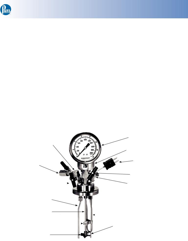
Pressure Gage
Safety Rupture Disc
|
|
Magnetic Drive |
|
|
Thermocouple |
Gas Inlet Valve |
|
|
|
|
Gas Release Valve |
Liquid Sampling Valve |
|
Vessel Water Cooling |
|
||
|
|
Channel |
Dip Tube
Stirring Shaft
Lower Guide |
|
|
|
Cooling Loop |
|
|
|
||
|
|
Thermocouple / Thermowell |
||
|
|
|||
Bearing |
|
|
||
|
|
|
|
|
Adjustable
Impeller(s)
Removable Head Shown (Standard Temperature, T316)
w w w . p a r r i n s t . c o m |
9 |
 Loading...