


4700
Table of contents
 Loading...
239M
4600 & 4700
General Purpose Pressure Vessels
Operating Instruction Manual

Table of Contents
PREFACE 3
Scope 3
Related Instructions 3
Intended Usage 3
Safety Information 3
Explanation of Symbols 4
Environmental Conditions 4
Unpack Carefully 4
Provisions for Lifting and Carrying 4
Cleaning and Maintenance 4
User’s Responsibility 5
Pressure and Temperature Limits 5
CLOSURES 6
Split Ring Closures 6
Split Ring Closure Operations 6
Screw Cap Closures 6
Operating 4700 Screw Cap Vessels 6
PARR PRESSURE VESSEL SEALS 7
Flat Gasket or Self Sealing O-ring Closure 7
Seals for Operating Temperatures up to 350 °C 7
Gaskets for Operating Temperature above 350 °C 7
Sealing the Vessel 7
Vessels with a Flat PTFE Gasket 7
Vessels with an O-ring seal 8
Vessels with a Flexible Graphite Gasket 8
Vessels with a Metal Gasket 8
Sealing 4740 High Pressure Vessels 9
HEAD ASSEMBLY GUIDE 12
MATERIAL DESIGNATIONS 12
Material Designations for Alloys other than T316SS 12
Gasket Material Designations 12
SERIES 4700 WORKING LIMITS AND PARTS LISTS 13
Series 4703-4714 13
Series 4740 14
Series 4750 15
Series 4760-4777 16
Series 4760Q-4777Q 18
Series 4790 20
SERIES 4600 WORKING LIMITS AND PARTS LISTS 22
Series 4600-4620 22
Series 4600Q-4620Q 23
Series 4605-4626 24
Series 4650 25
Series 4660 26
Series 4660Q 27
Series 4670-4674 28
Series 4676-4677 29
Series 4678-4679 30
Series 4680 31
4316 & 4317 GAGE BLOCK ASSEMBLIES 32
Gage Block Parts List 32
Gage Block Assembly Drawing 34
OTHER VESSEL HEAD FITTINGS 9
Gage Block Assemblies 9
Pressure Gages 9
Safety Rupture Discs 9
Coned Pressure Fittings 9
Tapered Pipe Threads 10
MAINTENANCE 10
General Maintenance Notes 10
Periodic Pressure Tests 11
2
Parr Instrument Company
Customer Service
Questions concerning the installation or operation
of this instrument can be answered by the Parr
Customer Service Department:
1-309-762-7716 • 1-800-872-7720
Fax: 1-309-762-9453
E-mail: parr@parrinst.com
http://www.parrinst.com

General Purpose Pressure Vessels
PREFACE
Scope
These instructions cover the basic operating steps
to be followed when using a variety of pressure vessels manufactured by the Parr Instrument Company.
They include temperature and pressure ratings for
Series 4600 and 4700 General Purpose Pressure Vessels, also instructions for the gage block assemblies
commonly used with these vessels. This material
is intended to be used in conjunction with several
related instruction sheets listed on page 2 covering
safety precautions and other information applicable
to Parr pressure equipment. The user should study
all of these instructions carefully before starting
to use any Parr pressure vessels in order to obtain
a complete understanding of the capabilities and
limitations of these vessels, and to be well aware of
the precautions to be observed in their operation.
Related Instructions
The following Parr publications are also included to
further your understanding of this instrument and
its component parts:
Intended Usage
This system has been designed for use as a high
pressure reactor system. It has been designed, built,
and tested to strict physical and electrical standards.
However, it is the user’s responsibility to install and
operate it in conformance with local pressure and
electrical codes.
If this equipment is used in a manner beyond its
intended usage, the protection provided by the
equipment may be impaired.
Safety Information
To avoid electrical shock, always:
1. Use a properly grounded electrical outlet of
correct voltage and current handling capability.
2. Ensure that the equipment is connected to
electrical service according to local national
electrical codes. Failure to properly connect may
create a fire or shock hazard.
3. For continued protection against possible
hazard, replace fuses with same type and rating
of fuse.
No. Description
201M Limited Warranty
230M Safety Precautions to be observed when
operating Pressure Reaction Equipment
231M Operating Instructions for Parr Safety
Rupture Discs
285M Sealing Instructions for Flexible
Graphite Gaskets
323M Operating Instructions for Pressure
Relief Valves
551M Operating Instructions for 4838
Temperature Controllers
FX004 Health & Safety Assurance Certification
4. Disconnect from the power supply before
maintenance or servicing.
To avoid personal injury:
1. Do not use in the presence of flammable or
combustible materials; fire or explosion may
result. This device contains components which
may ignite such material.
2. Refer servicing to qualified personnel.
www.parrinst.com
3
General Purpose Pressure Vessels
Explanation of Symbols
II On position, full power heater switch
I On position, half power heater switch
O Off Position
~ Alternating Current (AC)
This CAUTION symbol may be present on the Product Instrumentation and
literature. If present on the product, the user must consult the appropriate
part of the accompanying product literature for more information.
This CAUTION symbol indicates that the surface may be hot.
Protective Earth (PE) terminal. Provided for connection of the Protective
Earth (green or green/yellow) supply system conductor.
Environmental Conditions
This instrument is intended to be used indoors.
Caution!
Do not use in hazardous atmospheres.
Operating: 15 ºC to 40 ºC; maximum relative humidity of 80% non-condensing. Installation Category II
(over voltage) in accordance with IEC 664. Pollution
degree 2 in accordance with IEC 664.
Altitude Limit: 0 to 6000 feet above sea level.
Storage: -25 °C to 65 °C; 10% to 85% relative humidity.
Unpack Carefully
Unpack the equipment carefully and check all the
parts against the packing list. If shipping damage
is discovered, report it immediately to the delivering carriers. The vessel, motor, heater, and temperature controller may be packed separately for
convenience in shipping, but these parts are easily
reassembled. Examine the components closely for
any loose parts or shipping damage and be sure to
check all layers of packing materials thoroughly so
as not to overlook any parts which might otherwise
be discarded.
Provisions for Lifting and Carrying
The Series 4600 and 4700 General Purpose Vessels
and their components are very heavy. Before
moving ensure all cables are disconnected. Use
proper and safe lifting techniques when installing or
moving the Series 4600 and 4700 General Purpose
Vessels and/ or its components.
Cleaning and Maintenance
Periodic cleaning may be performed on the exterior
surfaces of the instrument with a lightly dampened
cloth containing mild soap solution. All power should
be disconnected when cleaning the instrument.
There are no user serviceable parts inside the product other than what is specifically called out and
discussed in this manual. Advanced troubleshooting
instructions beyond the scope of this manual can
be obtained by calling Parr Instrument Company in
order to determine which part(s) may be replaced or
serviced.
Ensure that any hot surfaces have had adequate
time to cool before cleaning or maintaining the
reactor and/or its components.
4
Parr Instrument Company

General Purpose Pressure Vessels
User’s Responsibility
All Parr Reactors and pressure vessels are designed
and manufactured with great care to assure safe
operation when used within their prescribed temperature and pressure limits. But . . . the basic
responsibility for safety when using this equipment
rests entirely with the user; who must:
1. Select a reactor or pressure vessel which has the
capability, pressure rating, corrosion resistance
and design features that are suitable for its intended use. Parr engineers will be glad to discuss available equipment and material options
with prospective users, but the final responsibility for selecting a reactor or pressure vessel
that will perform to the user’s satisfaction in any
particular reaction or test must rest with the user
– not with Parr.
In exercising the responsibility for the selection
of pressure equipment, the prospective user
is often faced with a choice between over- or
under-designed equipment. The hazards introduced by under-designed pressure vessels are
readily apparent, but the penalties that must
be paid for over-designed apparatus are often
overlooked.
Recognizing these criteria, Parr reactors and
pressure vessels are offered in several different
styles, each designed for convenient use in daily
operation within certain temperature and pressure limits, using gaskets, closures and other
elements carefully selected for safe operation
within the limits specified for that design. But in
order to preserve the validity of these designs,
all temperature and pressure limits must be
observed, and no attempt should be made to
increase these limits by making alterations or by
substituting components which are not recommended by Parr Instrument Company.
2. Install and operate the equipment within a
suitable barricade, if required, with appropriate
safety accessories and in full compliance with
local safety codes and rules.
All standard Parr pressure vessels are provided
with either a suitable relief device or a means
to attach one (typically in the form of a plugged
opening). When a pressure vessel is delivered
without a pressure venting device, it is the customer’s responsibility to provide pressure relief
in order to protect the operator and the equipment from destructive high pressures. If you
need more information or need help in selecting
a proper relief device, please contact Parr Instrument Company.
3. Establish training procedures to ensure that any
person handling the equipment knows how to
use it properly.
4. Maintain the equipment in good condition and
establish procedures for periodic testing to be
sure the vessel remains structurally sound.
Pressure and Temperature Limits
The working pressure and temperature at which any
reactor or pressure vessel can be used will depend
upon the design of the vessel and the materials
used in its construction. Since all materials lose
strength at elevated temperatures, any pressure
rating must be stated in terms of the temperature at
which it applies. The standard material of construction for Parr Instrument Company is Type 316 Stainless Steel.
Limits for vessels made of other materials and for
other operating temperatures can be obtained from
Parr Customer Service. No attempt should be made
to increase these limits by making alterations or by
substituting components that are not recommended
by the Parr Instrument Company. It must also be
understood that lower pressure and temperature
limits may be required for modified reactors and for
vessels made of special alloys.
Limits for vessels will be determined by the physical characteristics of the vessel material and will be
prescribed on an individual basis.
The maximum working pressure and temperature
for any vessel is governed by the design of the
vessel and the strength of the material from which
it is constructed. There is also a close relationship
between working pressure and temperature since
the strength of any material will normally fall off
as the temperature is increased. Temperature and
pressure limits are also affected by the physical
properties and temperature limits of the gaskets and
seals used in the vessel, and by any valves, gages
or other fittings attached to the vessel. Obviously,
the safe operating pressure of any system can be no
higher than that of its lowest rated component.
All Parr reactors show the maximum safe operating
pressure and temperature imprinted on the cylinder.
www.parrinst.com
5
General Purpose Pressure Vessels
CLOSURES
Split Ring Closures
Most Parr pressure vessels are equipped with
a unique split ring cover
clamp in which the head
of the vessel is clamped to
the cylinder by a hardened
steel ring which has been
split into two sections.
These sections slide into
place from the sides
without interfering with
any fittings attached to the
head.
The closing force is developed by simply tightening
a set of compression bolts
in the ring sections with a
hand wrench. As a further
convenience, larger Parr
vessels in one and two
gallon sizes, and certain
high temperature and
high pressure vessels, are
equipped with split ring
closures which do not
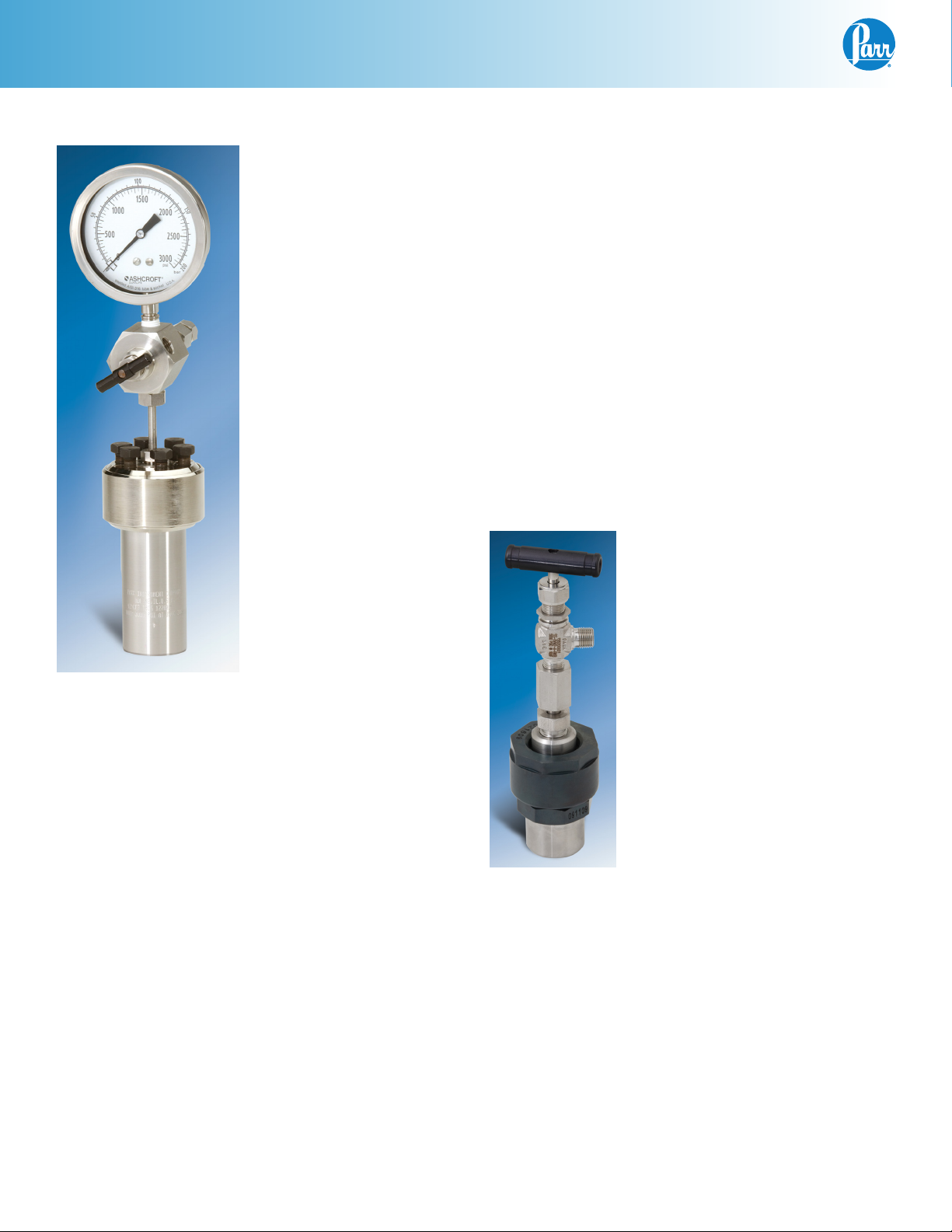
4751 125 mL Vessel with
Split Ring Closure and
4316 Gage Block Assembly
simply sliding the split ring section into place from
the sides and tightening the compression bolts
while the cylinder remains in place in its heater or
other fixed support.
Split Ring Closure Operations
All vessels with split ring closures, except the larger
Series 4660, 4670 and 4680 sizes, must be removed
from the heater and set on a bench or table top
before attempting to remove the split rings and
head.
1. To Open the Vessel: open the gas release valve
to discharge any internal pressure; then loosen
the compression bolts in the split ring sections.
Loosen the cone pointed screw in the outer band
and lower the band to rest on the table. The ring
sections can now be removed, and the head with
all attached fittings is free to be lifted from the
cylinder.
require an outer retaining
ring or drop band. This
allows the vessel to be
opened and closed by
2. Before Closing the Vessel: examine the head seal
carefully to be sure that it is in good condition.
The seal should not have any nicks or be hardened, discolored, or deformed. Examine the
mating surfaces on the cylinder and head to be
sure they are clean and free from burrs; then set
the head on the cylinder.
3. To Close the Vessel: put the two split ring halves
around the head and cylinder flanges, fasten the
latches or tighten the bolts as assembled before.
4. Routinely inspect the bolts on split ring closures for lubrication and cleanliness. These
screws should not be allowed to dry because
the threads will seize. Regularly apply Parr High
Temperature Anti-Seize Lubricant before this
happens.
Screw Cap Closures
On the smallest Parr vessels a
threaded sleeve and screw cap
are used to clamp the head to a
cylinder. This is a union type coupling in which proper alignment
between the head and cylinder
is always assured since neither
of these parts rotates when the
screw cap is tightened. The flat
gasket is held in a recess in the
head. The seal is made as the
lip of the cylinder is compressed
against the gasket through tightening the screw cap and sleeve.
All components must be kept
clean. The gasket must be replaced whenever it becomes worn
4703 22 mL Screw
Cap Vessel
or damaged. Any nicks in gasket
recess area or to the sealing face
of the cylinder must be avoided.
Operating 4700 Screw Cap Vessels
To close the Series 4700 Screw Cap Vessels: raise
the sleeve against the top rim of the cylinder; set
the head on the cylinder and attach the screw cap.
Turn the screw cap down until it is finger tight; then
set the vessel in a Parr A22AC3 bench socket and
tighten the cap firmly with a 21AC4 box wrench.
6
Parr Instrument Company

General Purpose Pressure Vessels
PARR PRESSURE VESSEL SEALS
Several different head sealing arrangements are
used in Parr Pressure Vessels, each selected for easy
access to the interior of the vessel as well as for
safe operation within the pressure and temperature
limits for which the vessel is designed. Both flat
compression type gaskets and O-rings are used in
these designs.
The various gasket materials used in Parr pressure
vessels are listed in Table I. Since several of these
materials are produced by different suppliers under
different trade names, the ASTM generic designation is used in these instructions to identify the type
of sealing material (or materials) recommended for
each Parr vessel.
Flat Gasket or Self Sealing O-ring Closure
The flat gasket is held in a recess in the vessel head
and a machine pilot on the cylinder closes the recess
to completely contain the gasket. The split ring closure used with this gasket has cap screws which must
be tightened to develop the loading on the gasket.
The self sealing design features an O-ring retained
in a groove on the vessel head. This design is self
sealing and the split ring used with this sealing
system does not require nor have the cap screws
used with the flat gasket.
The flat PTFE gasket can be used to operating temperatures as high as 350 °C. The flat flexible graphite
(FG) gasket can be used to operating temperatures
as high as 600 °C.
O-rings are available in several different materials
for use within the temperature limit listed in the
following table.
Pressure and Temperature Limits
O-Ring Material Maximum Temperature
NBR 150 °C
FKM 225 °C
FFKM 300 °C
PTFE 350 °C
Gaskets for Operating Temperature above 350 °C
Parr uses a flexible form of graphite which has
proven to be an excellent high temperature sealing
material. It has almost unlimited temperature range,
retaining its structure at temperatures well above the
maximum at which a metal gasket can operate, and
offering broad corrosion resistance as well.
Metal Gaskets can be furnished if required for special
applications. These are usually made of stainless
steel machined to a unique diamond shape with
edges which fit into supporting grooves in the head
and cylinder of the vessel. This type of gasket requires careful maintenance and a uniform loading applied by tightening a ring of compression bolts with a
torque wrench. For easier handling, Parr has replaced
its diamond shaped metal gaskets with flat, flexible
graphite gaskets (FG) described above. But it will
continue to furnish metal gaskets in custom vessels
for applications in which a metal gasket appears to
offer the best solution to a difficult sealing problem.
Sealing the Vessel
The maximum temperature of the vessels equipped
with O-ring seals depends upon the material used
for the O-ring. The most common material is a fluoroelastomer (FKM) which has a 225 °C maximum
operating temperature limit.
Seals for Operating Temperatures up to 350 °C
Parr uses both flat contained gaskets and O-rings
made of different materials, each with a different
maximum working temperature. Flat gaskets made
of PTFE fluoropolymer resins are the recommended
choice for many applications since PTFE materials are inert to most chemicals. PTFE gaskets will
provide good seals under repeated opening and
closing of the vessel if the gasket temperature does
not exceed 350 °C.
Vessels with split ring closures are sealed by tightening the compression bolts in the split ring sections with a wrench furnished with the apparatus. To
ensure uniform loading, turn down each bolt finger
tight, then tighten to the limit described below for
the type of gasket being used. Do not over-tighten
the compression bolts as this can generate excessive strain on the closure.
Vessels with a Flat PTFE Gasket
Tighten the compression bolts using a criss-cross
pattern, applying a firm but hard pull to each
screw. Use a torque wrench to apply 25 ft-lbs to
each compression bolt. Let the vessel stand for
about five minutes after the initial tightening, then
tighten again to 25-ft lbs. This will compensate for
any tendency of the PTFE gasket to flow under the
loading pressure.
www.parrinst.com
7

General Purpose Pressure Vessels
Vessels with an O-ring seal
The self-sealing design features an O-ring retained
in a groove on the vessel head. This design is self
sealing and the split ring does not require or have
the compression bolts used with the flat gasket.
Vessels with a Flexible Graphite Gasket
The closure bolts may be tightened using either an
open-end wrench for smaller vessels where the bolt
torque requirement is less or with a torque wrench
where additional loading is required for the higher
operating pressures.
Some of the gasket numbers shown in the attached
table are furnished with vessels that have different
maximum working pressures. We have shown the
maximum torque value to correlate to the maximum
working pressure of the vessel.
It is important to make sure that the bolts are
periodically lubricated with a high-temp anti-seize
compound to insure that they move freely so that
the desired torque value is obtained in the tightening procedure.
It is also important to insure that there is uniform
loading on all of the bolts. Make sure that the head
sits levelly on the cylinder. Install the split ring and
tighten all bolts finger tight.
Pick a starting position and tighten the bolt to 5 or 10
ft-lbs depending on the maximum amount of torque
to be applied. For those vessels with a maximum
torque requirement of 15 ft-lbs, a 5 ft-lb increment
is appropriate. For vessels with a maximum of 135
ft-lbs, 20 ft-lb increments may be used.
Bolt tightening should continue in a criss-cross
pattern from the initial bolt with the second bolt 180
degrees from the first and continuing until all bolts
are tightened. Repeat this procedure increasing the
torque to the required level as shown in the table
below.
Torque Required For Sealing Vessels
with Flexible Graphite Gaskets
Vessel
Series
No.
4600 1900 315HC4KL 35
4790 3000 to 5000 429HC2KL 15
4760 3000 457HC3KL 35
4650 5000 to 6000 457HC3KL 40
4660 190 0 655HC3KL 35
4680 5000 1808HCKL 40
4670 3000 1812HCKL 35
4740 8500 1829HCKL 15
4676 190 0 1559HC2KL 135
Note: It may be possible to extend the life of
the Flexible Graphite gasket by coating both
sealing surfaces of the head and cylinder as
well as the gasket itself with a silicone base
lubricant. Additionally, it helps to rough up
the cylinder lip with 120 grit sandpaper to
insure that the gasket remains in the head
recess and does not stick to the cylinder.
Vessels with a Metal Gasket
Pressure vessels with a metal gasket require a
uniform loading on the gasket carefully applied by
tightening a ring of compression bolts with a torque
wrench. The amount of torque to be applied will
vary with different vessels and with the intended
maximum working pressure. Specific sealing
instructions will be provided for any Parr pressure
vessels with a metal gasket furnished on special
order.
Maximum
Working
Pressure, PSI
Graphite
Gasket
No.
Torque
Required
ft-lb
8
Parr Instrument Company
General Purpose Pressure Vessels
G
y
Sealing 4740 High Pressure Vessels
Closing operations for the 1.0 inch I.D., Series 4740
high pressure vessels are similar to those described
for larger vessels with flexible graphite gaskets,
except on the 4740 Series the compression screws
are carried in a screw cap instead of in a split ring.
When closing a 4740, clamp the cylinder in a vise;
check the graphite gasket to be sure that it fits properly in the head groove; set the head on the cylinder
and add the compression ring. Check the screw cap
to be sure that the six screws have been turned back
so that they do not project through the cap, and then
screw the cap onto the cylinder. Turn it down as far
as it will go, then back it off about 1/8 turn. Now,
tighten the screws with a torque wrench with an
initial 10 ft-lbs using the criss-cross pattern described
for larger vessels. After all have been tightened to
10 ft-lbs, repeat the procedure, increasing the torque
until all have been tightened to the recommended 15
ft-lb limit.
OTHER VESSEL HEAD FITTINGS
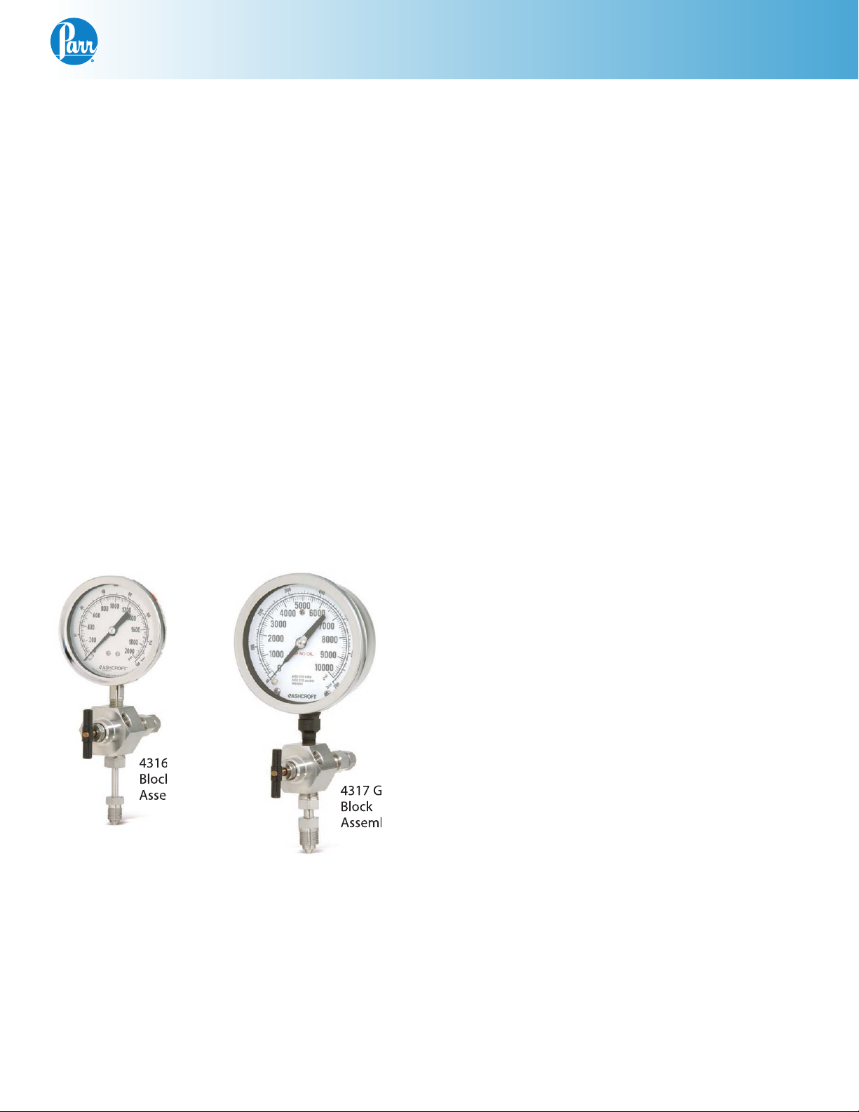
Gage Block Assemblies
age
mbl
age
The valve in this assembly controls the flow of gas
into the vessel and the gage shows the internal
pressure when the valve is closed. Two styles are
offered: The 4316 gage block assembly has a 3-1/2”
dia. pressure gage and a Type A socket connector.
This unit is normally used on smaller vessels where
space is limited.
The 4317 gage block assembly has a 4-1/2” dia. gage
and a Type B connector. It is typically furnished on
vessels one liter and larger.
Pressure Gages
Pressure gages display in both psi and bar in various ranges for use on Parr gage block assemblies.
The available ranges are shown in the gage block
parts list. All of these gages have stainless steel
cases with T316SS Bourdon tubes and ¼” NPT male
connections. Gages constructed of Alloy 400 are
available on special order.
Safety Rupture Discs
Detailed instructions for the safety rupture disc
installed in Parr gage blocks and heads are provided
in a separate Instruction Sheet No. 231M. The user
should review these instructions carefully. Please
note that the operating pressures in the vessel
should not exceed 90% of the range of the pressure
gage and rupture disc. Also note the warning that
the discharge port from the rupture disc must always
be directed away from all operating personnel. A
compression fitting for use with 3/8” O.D. tubing is
attached to the rupture disc body. It is recommended that tubing be attached to this connector to carry
any discharge to a fume hood or safe area in the
event of an over-pressure. The free or discharge end
of any attached tubing must be anchored securely.
Coned Pressure Fittings
The coned pressure fittings used to connect gage
blocks, pressure hoses and other detachable parts
Parr gage block assemblies combine the function of
an inlet valve, a pressure gage and a safety rupture
disc in a compact assembly on a block which can
be attached to the head of a pressure vessel with a
single connecting tube. There is a threaded socket
in the block for a gas connection with a pressure
hose or tubing using a Type A coned pressure fitting.
Coned pressure fittings are also used on the tube
which connects the block to the pressure vessel.
to Parr pressure vessels are illustrated below. These
fittings have a sleeve with a left-handed thread
which screws onto the end of a thick-walled tube
plus a compression nut to complete the assembly.
When screwed into a matching socket, these parts
form a rigid joint which will remain tight over a wide
temperature and pressure range, yet the joint can be
made and broken repeatedly without destroying the
sealing faces. No gasket is required.
www.parrinst.com
9
General Purpose Pressure Vessels
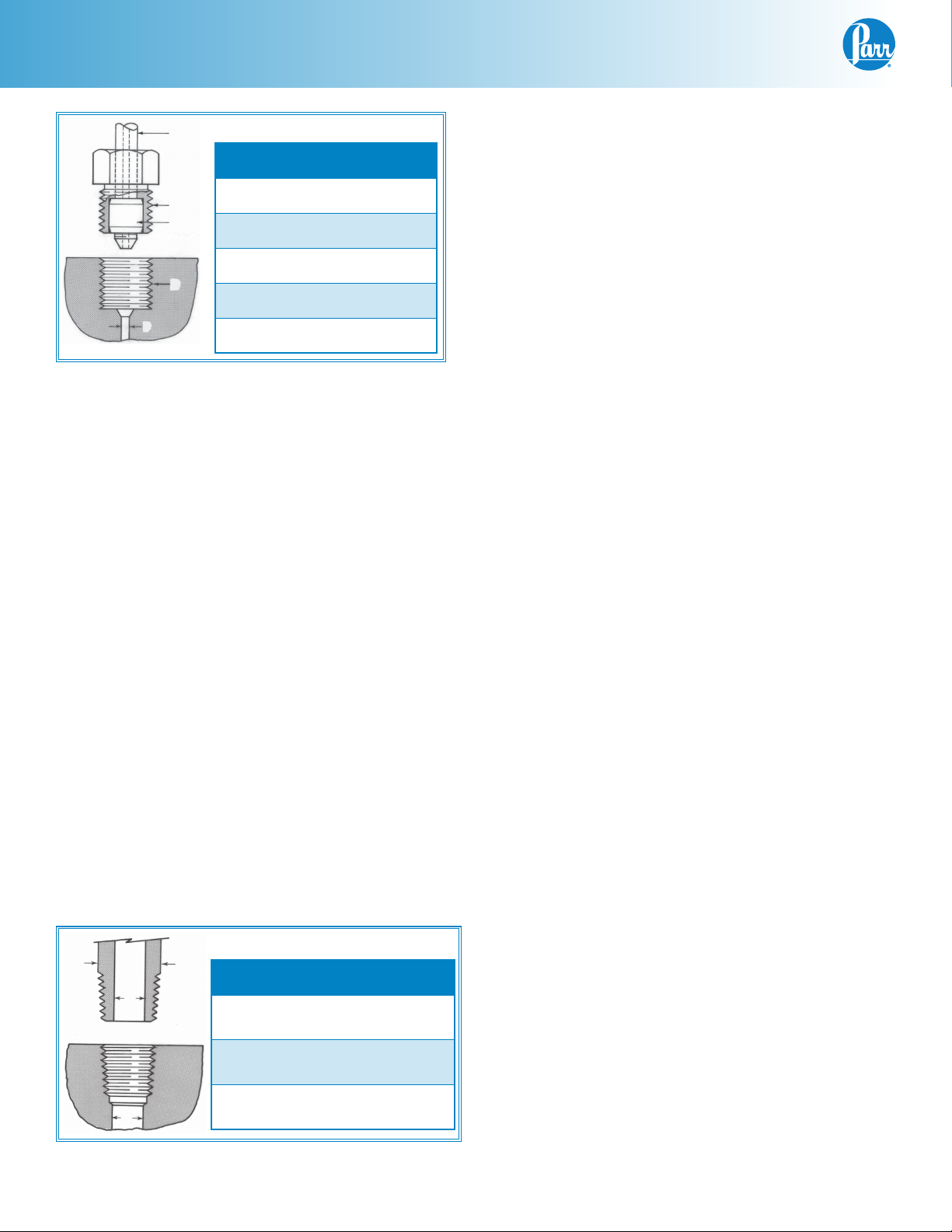
TUBING
Coned Pressure Fittings
Type A B
NUT
BUSHING
D
E
Tube Size 1/4” 3/8”
Thread (D) 9/16-18 3/4-16
Bore (E) 3/32” 1/8”
Nut No. 35HC 326HC
Bushing No.
40HC 366HC
When using these coned connectors, screw the
bushing onto the tube as far as it will go; then insert
the end of the tube into the head or gage block and
tighten the compression nut firmly while holding the
block stationary with the gage facing in the desired
direction. Note that this assembly behaves like a
pipe union, allowing the connecting tube or hose to
remain stationary while the joint is tightened.
Note: PTFE tape is not required on these connectors.
MAINTENANCE
General Maintenance Notes
1. Periodically inspect all electrical wiring and pressure connections for excessive corrosion. Suspect parts should be replaced by components
only supplied by Parr Instrument Company.
2. Always use appropriate wrenches on all fittings
and valves. Never use pliers or pipe wrenches.
3. Head and cylinder service fixtures are available
for convenience and protection of components
during maintenance of your reactor.
Note: For more information about available
service fixtures, reference TechNote 307.
4. A light coating of thread lubricant, such as Parr
High Temperature Anti-Seize Lubricant, (424HC2)
should be applied to the straight threads of
coned pressure connections as well as to the
nose of the mating piece this will help to obtain
a tight joint.
Tapered Pipe Threads
The pressure gage, needle valves and other fixed
attachments on Parr vessel heads have tapered pipe
threads which are not to be disturbed after they
have been screwed into place. If it becomes necessary to remove any of these fittings, the pipe threads
must be coated with PTFE tape, flexible graphite
tape, or similar luting material on reassembly.
The ID of a pipe or pipe fitting can be enlarged to
accommodate a tubing feed-thru. Note that, in some
cases, this may cause a reduction of the pressure
rating. The port below a female pipe connection can
also be opened up to a larger size.
The maximum openings are shown in the table below.
Tapered Pipe Threads
A
Nominal Size
B
Pipe OD (A) 0.405” 0.540”
Maximum
Feed-thru (B)
Maximum Exit
C
Port (C)
1/8” 1/4”
1/4” 3/8”
0.339” 0.458”
Note: PTFE tape should be used only on
all tapered (NPT) threads not NPS straight
threads.
5. NPT (National Pipe Taper) threads should not be
disassembled any more than necessary. It will
become increasingly difficult to maintain a tight
seal with these tapered threads if the joint is
made and broken repeatedly.
6. Do not use oil or anti-seize lubricant on threads
or fittings if the vessel is to be used with oxygen.
7. If your vessel is equipped with a loose compression ring be sure that it is in place on the head
before attaching any head fittings. The compression ring cannot be installed after fittings have
been screwed into the head.
10
Parr Instrument Company

General Purpose Pressure Vessels
8. Clean all threads and gas passages thoroughly
and remove all tape fragments when overhauling a vessel. An ultrasonic bath is excellent for
cleaning metal parts, but do not place a thermocouple probe, pressure gage, face seals or ball
bearings in an ultrasonic bath. Periodic cleaning
may be performed on the exterior surfaces of
the reactor stand with a damp cloth. All power
should be disconnected when cleaning.
9. Routinely inspect the bolts on split ring closures for lubrication and cleanliness. These
screws should not be allowed to dry because
the threads will seize. Regularly apply Parr High
Temperature Anti-Seize Lubricant before this
happens. It is important to keep the bolts lubricated so they will not seize and also to achieve
the intended torque value.
10. Routinely inspect screw cap threads for wear
and cleanliness.
11. If servicing assistance is needed, contact Parr Instrument Company direct at the address shown
on the back of these instructions.
Periodic Pressure Tests
Each cylinder used in a Parr pressure vessel is tested
under hydrostatic pressure at room temperature to
the higher of 1.43 times the rated working pressure
or 1.30 times the rated working pressure corrected
for room temperature before it is released from
the factory. Micrometer caliper measurements are
taken during this test to check the deflection of the
walls under pressure. Excessive deflection or failure
of the metal to resume its original dimensions after
pressure is released indicates that a cylinder is potentially unsafe and it will be rejected. Similar tests
should be made at regular intervals during the life
of each cylinder, and particularly whenever the user
suspects that the equipment has been over-stressed
or damaged.
Some laboratories maintain hydraulic test facilities
and make it a rule that all pressure vessels must
be tested at regular intervals. Records are kept of
deflections at specific test pressures so that any
increase in deflection becomes a warning that the
metal has lost strength. Any cylinder that fails to
return to its original dimensions after application of
the prescribed hydrostatic test should be discarded
as unsafe for further use.
Users who do not have pressure test facilities can
return any Parr pressure vessel to the factory for hydrostatic testing and overhaul. This should be done
whenever the metal shows excessive damage from
corrosion or whenever an over-pressure or other
unusual occurrence raises any safety questions.
To return a vessel for repair, contact Parr Instrument
Company for a return authorization number (RMA).
Apparatus returned for testing and overhaul should
be shipped prepaid to the following address:
Ship repair to:
Parr Instrument Company
Attn: Service Department
RMA # XXXXXX
211 53rd Street
Moline, Illinois 61265
USA
An order or letter of instructions should be mailed to
the same address, as no repair work will be started
without specific instructions and a Health & Safety
Assurance Certification form (FX004) signed by a
responsible user.
www.parrinst.com
11
Loading...