


6400
Table of contents
 Loading...
587M
6400
Automatic Isoperibol Calorimeter
Operating Instruction Manual
For models produced after October 2010


www.parrinst.com
Table of Contents6400
1
Preface 4
Scope 4
Related Instructions 4
Purpose 4
Explanation of Symbols 5
Safety Information 5
Intended Usage 5
General Specifications 6
Environmental Conditions 6
Provisions for Lifting and Carrying 6
Cleaning & Maintenance 6
Chapter 1 8
Installation 8
Environmental Conditions 8
Swagelok Tube Fittings 8
Required Consumables, Utilities and Power Requirements 9
Electrical Connection 9
Front Panel Meter 9
Water Connection 11
Gas Connection 12
Bomb Exhaust Connections 12
Communication Connections 13
Printer Connections 13
Balance Connections 13
Chapter 2 16
Quick Start 16
Initial Fill 16
Quick Start 16
Chapter 3 18
Operation 18
Menu System 18
Menu Keys 18
Control Keys 18
Programming 19
Default Settings 19
Sample Preparation 19
Test Process 22
Closing the bomb 22
Cool/Rinse 26
Drain
Fill Cycle 23
Pre-Period 24
Bomb Firing 25
Post-Period 25
Chapter 4 28
Menu Descriptions 28
Main Menu 28
Calorimeter Operation Menu 28
Temperature vs. Time Plot 29
Temperature Plot Setup Menu 29
Operating Controls Menu 30
Spiking Controls 30
Bomb Rinse Tank Controls 31
Program Information and Control Menu 32
Software & Hardware Info 32
User/Factory Settings 33
Calibration Data and Controls Menu 34
Bomb 1 35
Control Plot Chart Plot 35
Thermochemical Corrections Menu 36
Calculation Factors Menu 37
Net Heat/Dry Heat Factors 38
Data Entry Controls Menu 38
Net Heat Data Entry Controls 39
Auto Sample ID Controls 39
Moisture Data Entry Controls 40
Preweigh Sample ID Controls 40
Reporting Controls Menu 40
Communication Controls Menu 41
Balance Port Communications 41
Balance Port Settings 42
File Management Menu 43
Run Data File Manager 43
Diagnostics Menu 44
Data Logger Controls 44
Data Log Items 45
User Defined Buttons 45
I/O Diagnostics:

Parr Instrument Company
Table of Contents
2
Chapter 5 46
Reports 46
Reports 46
Chapter 6 48
Standardizations 48
Standardizing the Calorimeter 48
Standard Materials 48
Automatic Statistical Calculations 48
Chapter 7 52
Calculations 52
Calculating the Heat of Combustion 52
General Calculations 52
Thermochemical Corrections 52
ASTM and ISO Methods Differ 53
Thermochemical Calculation Details 54
Acid and Sulfur Corrections 54
ASTM Treatment for Acid and Sulfur 56
ISO Calculations 56
Spiking Samples 57
Conversion to Other Moisture Bases 57
Conversion to Net Heat of Combustion 57
Chapter 8 58
Computer Communications 58
Computer Connections 58
Samba Server Feature (Optional) 59
Bar Code Port 66
Chapter 9 68
Memory Management 68
Clearing Memory 68
Removable SD Memory 68
Chapter 10 70
Maintenance 70
Inspection of Critical Sealing Surfaces 70
Bomb Removal 70
Fuses 71
Daily Maintenance 71
Quarterly Maintenance 71
50 to 100 Test Maintenance 71
500 Test Maintenance 71
5000 Test Maintenance 72
6400 Maintenance Checklist 73
Chapter 11 74
Troubleshooting 74
Bomb Exhaust Troubleshooting 74
Jacket Temperature Troubleshooting 75
Error List 76
Chapter 12 78
Technical Service 78
Return for Repair 78
Chapter 13 80
Parts Lists 80
Principal Assemblies in Calorimeter 80
A1250DD2 Controller Assembly 80
A1265DD Bucket and Stirrer Tube Assembly 80
A1255DD Bucket Stirrer Assembly 81
A1266DD Cover Assembly 81
A1457DD Accessory/Installation Kit 81
Chapter 14 82
Drawings 82
1138 Parts Diagram Key 83
Chapter 15 104
Tables 104

www.parrinst.com
Table of Contents6400
3
Figures
Figure 1-1
Swagelok Tube Fittings 8
Figure 1-2
6400 Calorimeter Back Panel 10
Figure 1-3
6400 External Plumbing 11
Figure 1-4
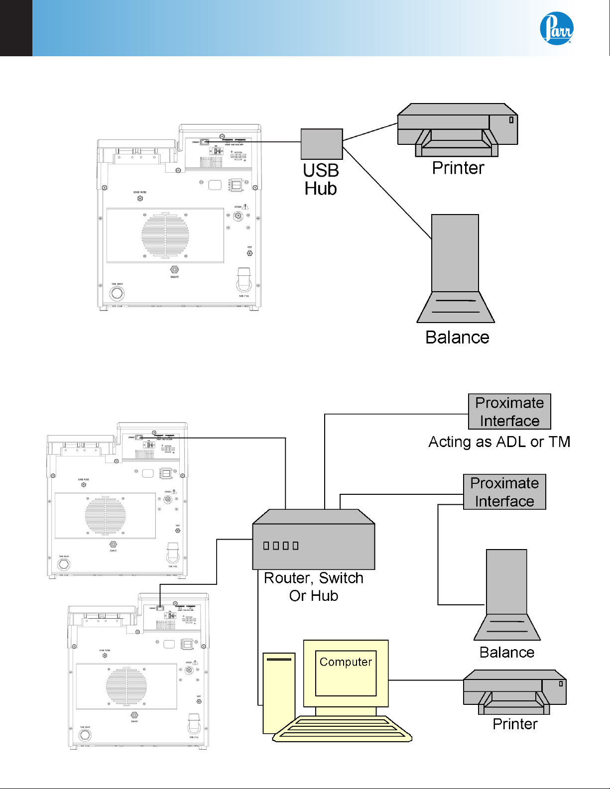
6400 Calorimeter Peripherals 14
Figure 1-5
Multiple Alternate Configurations 14
Figure 3-1
Volatile Sample Technique 21
Figure 3-2
Cotton Thread Assembly 22
Figure 3-3
Bucket Fill Flow Diagram 23
Figure 3-4
Pre-Period/Post-Period Flow Diagram 24
Figure 3-5
Rinse & Cool Flow Diagram 26
Figure 3-6
Drain Flow Diagram 27
Figure 14-1
1138 Parts Diagram 82
Figure 14-2
6400 Cutaway Right 84
Figure 14-3
6400 Cutaway Left 85
Figure 14-4
6400 Cover Open 86
Figure 14-5
A1250DD2 Control Schematic 87
Figure 14-6
A1251DD Oxygen Solenoid Assembly 88
Figure 14-7
A1447DD Water Solenoid Assembly 88
Figure 14-8
A1456DD Rinse Valve Assembly 89
Figure 14-9
6400 Internal Plumbing Diagram 90
Figure 14-10
6400 Water Tank and Jacket Cooling Solenoid 91
Tables
Table 6-1
Calorimeter Control Limit Values in J/g When Benzoic
Acid is Used as a Test Sample 49
Table 6-2
Calorimeter Control Limit Values in cal/g When Benzoic
Acid is Used as a Test Sample 50
Table 6-3
Calorimeter Control Limit Values in BTU/lb When Benzoic
Acid is Used as a Test Sample 51
Table 8-1
6400 Data File Naming Convention 66
Table 8-2
6400 Calorimeter Run Data Template 67
Table 15-1
Factory Default Settings 104
Table 15-2
Settings for ISO & BSI Methods 106
Figure 14-11
A1455DD Propeller Assembly 92
Figure 14-12
A1448DD Temperature Control Assembly 92
Figure 14-13
A1268DD Stirrer Motor and Mount 93
Figure 14-14
6400 Bucket Assembly 94
Figure 14-15
6400 Air Can Assembly, Cutaway Left 95
Figure 14-16
6400 Air Can Assembly, Cutaway Front 96
Figure 14-17
A1450DD Bomb Head Assembly, View 1 97
Figure 14-18
A1450DD Bomb Head Assembly, View 2 98
Figure 14-19
A1050DD Rinse Collection Assembly 99
Figure 14-20
Wiring Diagram 100
Figure 14-21
Wiring Diagram 101
Figure 14-22
Fuse Diagram 102

Preface
Parr Instrument Company
4
Preface
Scope
This manual contains instructions for installing and
operating the Parr 6400 Calorimeter. For ease of
use, the manual is divided into 15 chapters.
1. Installation
2. Quick Start
3. Operation
4. Menu Descriptions
5. Reports
6. Standardizations
7. Calculations
8. Computer Communications
9. Memory Management
10. Maintenance
11. Troubleshooting
12. Technical Service
13. Parts Lists
14. Drawings
15. Tables
Subsections of these chapters are identified in the
Table of Contents.
To assure successful installation and operation, the
user must study all instructions carefully before
starting to use the calorimeter to obtain an under-
standing of the capabilities of the equipment and the
safety precautions to be observed in the operation.
Related Instructions
Additional instructions concerning the installation
and operation of various component parts and
peripheral items used with the 6400 Calorimeter
should be made a part of these instructions. Addi-
tional instructions for the optional printer are found
in the respective printer package and should be
made a part of this book.
No. Description
201M Limited Warranty
207M Analytical Methods for Oxygen Bombs
230M Safety in the Operation of Laboratory
and Pressure Vessels
483M Introduction to Bomb Calorimetry
Note: The unit of heat used in this manual is
the International Table calorie, which is equal
to 4.1868 absolute joules.
Purpose
Heats of combustion, as determined in an oxygen
bomb calorimeter such as the 6400 Automatic
Isoperibol Calorimeter, are measured by a substitu-
tion procedure in which the heat obtained from the
sample is compared with the heat obtained from a
standardizing material. In this test, a representative
sample is burned in a high-pressure oxygen atmo-
sphere within a metal pressure vessel or “bomb”.
The energy released by the combustion is absorbed
within the calorimeter and the resulting temperature
change is recorded.
Customer Service
Questions concerning the installation or operation of this instrument
can be answered by the Parr Customer Service Department:
1-309-762-7716 • 1-800-872-7720 • Fax: 1-309-762-9453
E-mail: parr@parrinst.com • http://www.parrinst.com
Note About Nomenclature:
Historically, burning a sample enclosed in a high pressure oxygen
environment is known as Oxygen Bomb Calorimetry and the vessel
containing the sample is known as an Oxygen Bomb. The terms
bomb and vessel are used interchangeably.
Preface
6400
www.parrinst.com
5
Safety Information
To avoid electrical shock, always:
1. Use a properly grounded electrical outlet of
correct voltage and current handling capability.
2. Ensure that the equipment is connected to
electrical service according to local national
electrical codes. Failure to properly connect may
create a fire or shock hazard.
3. For continued protection against possible
hazard, replace fuses with same type and rating
of fuse.
4. Disconnect from the power supply before
maintenance or servicing.
To avoid personal injury:
1. Do not use in the presence of flammable or
combustible materials; fire or explosion may
result. This device contains components which
may ignite such material.
2. Refer servicing to qualified personnel.
Intended Usage
If the instrument is used in a manner not specified
by Parr Instrument Company, the protection pro-
vided by the equipment may be impaired.
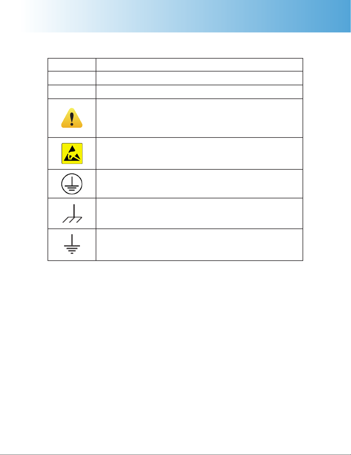
Explanation of Symbols
I On Position
O Off Position
~ Alternating Current
This CAUTION symbol may be present on the Product Instrumenta-
tion and literature. If present on the product, the user must consult
the appropriate part of the accompanying product literature for more
information.
ATTENTION, Electrostatic Discharge (ESD) hazards. Observe precau-
tions for handling electrostatic sensitive devices.
Protective Earth (PE) terminal. Provided for connection of the protec-
tive earth (green or green/yellow) supply system conductor.
Chassis Ground. Identifies a connection to the chassis or frame of the
equipment shall be bonded to Protective Earth at the source of supply
in accordance with national and local electrical code requirements.
Earth Ground. Functional earth connection. This connection shall be
bonded to Protective earth at the source of supply in accordance with
national and local electrical code requirements.

Preface
Parr Instrument Company
6
General Specifications
Electrical Ratings
120VAC, 5.0 Amps. 50/60 Hz
240VAC, 3.0 Amps. 50/60 Hz
Before connecting the calorimeter to an electrical
outlet, the user must be certain that the electrical
outlet has an earth ground connection and that the
line, load and other characteristics of the installation
do not exceed the following limits:
Voltage: Fluctuations in the line voltage should not
exceed 10% of the rated nominal voltage shown on
the data plate.
Frequency: Calorimeters can be operated from
either a 50 or 60 Hertz power supply without affect-
ing the operation or calibration.
Current: The total current drawn should not exceed
the rating shown on the data plate on the calorim-
eter by more than 10 percent.
Environmental Conditions
Operating: 15 ºC to 30 ºC; maximum relative humid-
ity of 80% non-condensing. Installation Category II
(over voltage) in accordance with IEC 664. Pollution
degree 2 in accordance with IEC 664.
Altitude Limit: 2,000 meters.
Storage: -25 ºC and 65 ºC; 10% to 85% relative humidity.
Provisions for Lifting and Carrying
Before moving the instrument, disconnect all con-
nections from the rear of the apparatus. Lift the
instrument by grabbing underneath each corner.
Cleaning & Maintenance
Periodic cleaning may be performed on the exterior
surfaces of the instrument with a lightly dampened
cloth containing mild soap solution. All power
should be disconnected when cleaning the instru-
ment. There are no user serviceable parts inside the
product other than what is specifically called out
and discussed in this manual. Advanced trouble-
shooting instructions beyond the scope of this
manual can be obtained by calling Parr Instrument
Company in order to determine which part(s) may
be replaced or serviced.

www.parrinst.com
7
Notes
6400
1
Installation
Parr Instrument Company
8
chaPter 1
Installation
Note: Some of the following manual sections
contain information in the form of warnings,
cautions and notes that require special at-
tention. Read and follow these instructions
carefully to avoid personal injury and dam-
age to the instrument. Only personnel quali-
fied to do so, should conduct the installation
tasks described in this portion of the manual.
Environmental Conditions
The 6400 Calorimeter is completely assembled and
given a thorough test before it is shipped from the
factory. If the user follows these instructions, instal-
lation of the calorimeter should be completed with
little or no difficulty. If the factory settings are not
disturbed, only minor adjustments will be needed to
adapt the calorimeter to operating conditions in the
user’s laboratory.
This apparatus is to be used indoors. It requires at
least 4 square feet of workspace on a sturdy bench
or table in a well-ventilated area with convenient
access to an electric outlet, running water and a
drain.
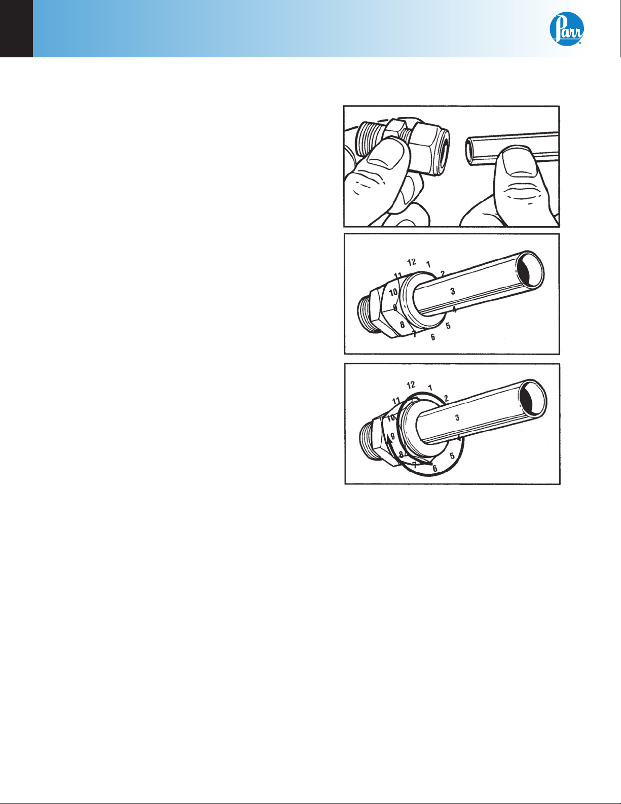
Swagelok Tube Fittings
When Swagelok Tube Fittings are used, the instruc-
tions for installation are:
1. Simply insert the tubing into the Swagelok Tube
Fitting. Make sure that the tubing rests firmly
on the shoulder of the fitting and that the nut is
finger-tight.
2. Before tightening the Swagelok nut, scribe the
nut at the 6 o’clock position.
3. While holding the fitting body steady with a
back-up wrench, tighten the nut 1-1/4 turns.
Watch the scribe mark, make one complete revo-
lution and continue to the 9 o’clock position.
4. For 3/16” and 4mm or smaller tube ttings, tight-
en the Swagelok nut 3/4 turns from nger-tight.
Figure 1-1
Swagelok Tube Fittings
Swagelok tubing connections can be disconnected
and retightened many times. The same reliable leak-
proof seal can be obtained every time the connec-
tion is remade using the simple two-step procedure.
1. Insert the tubing with pre-swaged ferrules into
the fitting body until the front ferrule seats.
2. Tighten the nut by hand. Rotate the nut to the
original position with a wrench. An increase in
resistance will be encountered at the original
position. Then tighten slightly with a wrench.
Smaller tube sizes (up to 3/16” or 4mm) take less
tightening to reach the original position than
larger tube sizes.

Installation
6400
1
www.parrinst.com
9
The type of tubing and the wall thickness also has
an effect on the amount of tightening required.
Plastic tubing requires a minimal amount of ad-
ditional tightening while heavy wall metal tubing
may require somewhat more tightening. In general,
the nut only needs to be tightened about 1/8 turn
beyond finger tight where the ferrule seats in order
to obtain a tight seal.
Over tightening the nut should be avoided. Over
tightening the nut causes distortion (flaring) of the
lip of the tube fitting where the ferrule seats. This
in turn causes the threaded portion of the body to
deform. It becomes difficult to tighten the nut by
hand during a subsequent re-tightening when the
fitting body becomes distorted in this manner.
Required Consumables, Utilities and Power
Requirements
The 6400 Calorimeter requires availability of
oxygen, 99.5% purity, with appropriate connection,
2500 psig, maximum.
The 6400 Calorimeter requires availability of ni-
trogen or air, oil and water free, with appropriate
connection, 2500 psig, maximum.
Approximately 16L of distilled water are required to
fill the external pressurized rinse tank.
Approximately 2L of distilled, de-ionized, or tap
water, with a total hardness of 85 ppm or less, are
required for filling the internal cooling reservoir.
The power requirements for the sub-assemblies of
the 6400 Calorimeter are:
Calorimeter
5.0 Amps @ 120 VAC
3.0 Amps @ 240 VAC
Printer
(100 to 240 VAC, 50/60 Hz) 0.35 Amps
Electrical Connection
Plug the power line into any grounded outlet provid-
ing proper voltage that matches the specification on
the nameplate of the calorimeter. Grounding is very
important not only as a safety measure, but also to
ensure satisfactory controller performance. If there
is any question about the reliability of the ground
connection through the power cord, run a separate
earth ground wire to the controller chassis.
Turn the power switch to the ON position. After
a short time, the Parr logo will appear on the LCD
display followed by a running description of the in-
strument boot sequence. When the boot sequence
is complete, the Main Menu is displayed.
Front Panel Meter
The panel meter on the front of the calorimeter
controls the temperature of the water in the internal
cooling resorvoir. The setpoint is locked at 15 °C.
A red light will flash in the upper left corner of the
display when the water is being cooled.
1
Installation
Parr Instrument Company
10
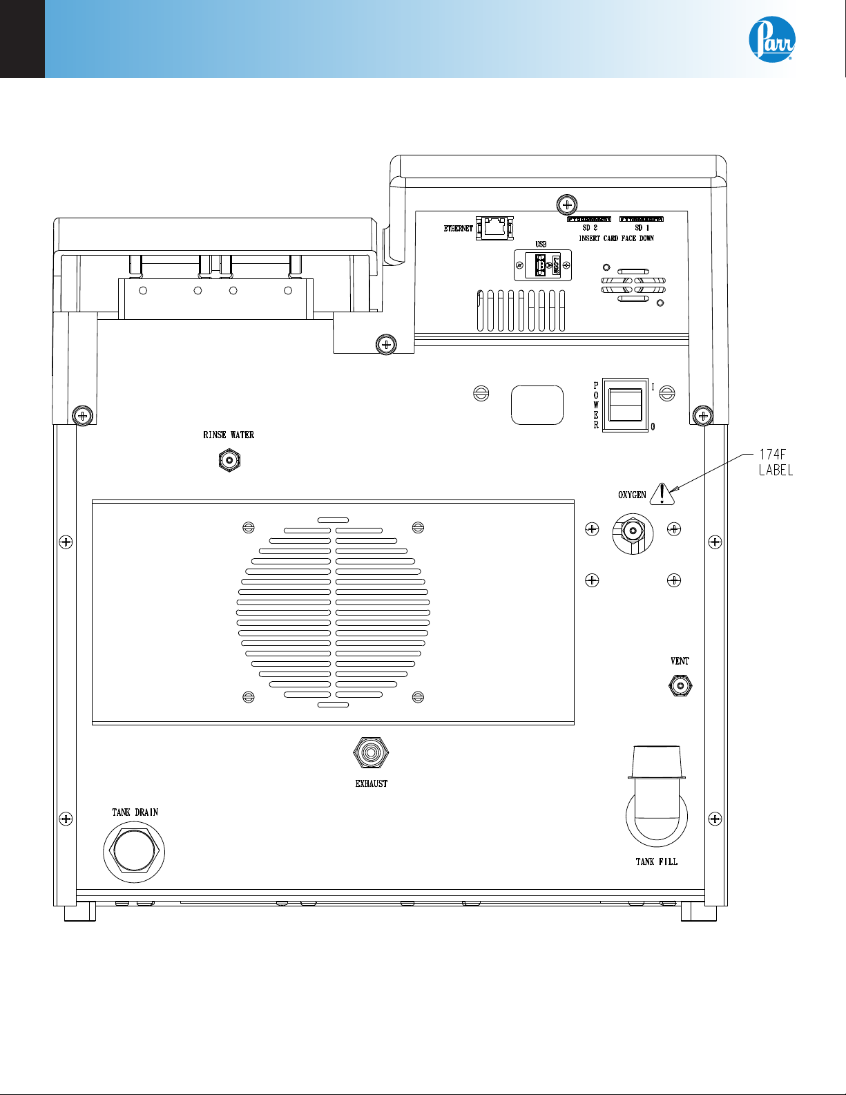
Figure 1-2
6400 Calorimeter Back Panel
Installation
6400
1
www.parrinst.com
11
Water Connection
Remove the cap plug on the water filling elbow and
fill the internal reservoir tank with water having a
total hardness of 85 ppm or less, until the water level
is at the bottom of the filling elbow. The calorimeter
water tank will initially accept about 2 liters.
Fill the external rinse tank with about 16 liters of
distilled water through the large opening at the top
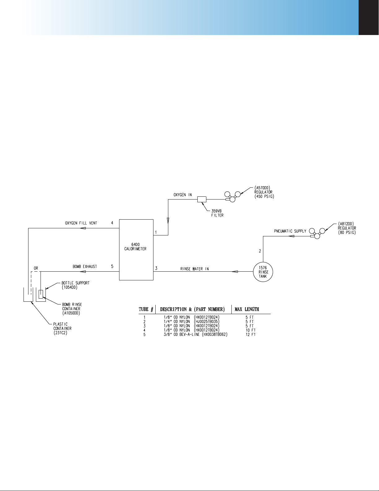
Figure 1-3
6400 External Plumbing
of the tank. The cover for this opening is removed
by lifting up on the handle, pushing down on the lid,
tilting and removing. Replace and close the cover
after filling.
The connection between the calorimeter and the
1576 Rinse Tank should be made with a piece of 1/8”
nylon pressure hose (HX0012TB024). See Figure 1-3.

1
Installation
Parr Instrument Company
12
Gas Connection
Make the connections to the oxygen supply at this
time. Refer to Figure 1-3. 1/8” O.D. nylon pressure
hose (HX0012TB024) is used to connect the oxygen
supply. The inlet connection incorporates a flow
restrictor just behind the inlet connection. When
making the oxygen connection, a back-up wrench
should be placed on the restrictor to insure a secure
connection and to prevent over tightening the flow
restrictor. The delivery pressure for oxygen should
be set to 450 psig. To install the regulator, unscrew
the protecting cap from the tank and inspect the
threads on the tank outlet to be sure they are clean
and in good condition. Place the ball end of the
regulator in the tank outlet and draw up the union
nut tightly, keeping the gages tilted slightly back
from an upright position. Open the tank valve and
check for leaks. The bomb must never be filled to
more than 600 psig (40 atm).
Make the connections to the nitrogen supply at this
time. 1/4” O.D. nylon pressure hose (HJ0025TB035)
is used to connect the A812DD Nitrogen Regulator
to the 1576 Rinse Tank. When making the nitrogen
connection, a back-up wrench should be placed on
the fitting to insure a secure connection and to pre-
vent over tightening the flow restrictor. The delivery
pressure for nitrogen should be set at 80 psig. To
install the regulator, unscrew the protecting cap
from the tank and inspect the threads on the tank
outlet to be sure they are clean and in good condi-
tion. Place the ball end of the regulator in the tank
outlet and draw up the union nut tightly, keeping the
gages tilted slightly back from an upright position.
Open the tank valve and check for leaks.
Note: A hissing sound will occur while the
rinse tank is being pressurized. This is nor-
mal. Adjust the pneumatic supply regulator
to 80 psig as needed.
During extended periods of inactivity, close the tank
valve to prevent depleting the tank in the event of
a leak. Close the tank valve prior to removing the
regulator when changing tanks. Do not use oil or
combustible lubricants in connection with any part
of the oxygen filling system. Keep all threads, fit-
tings and gaskets clean and in good condition.
Note: To release the pressure inside the rinse
tank turn off the gas supply and open the gas
relief valve lever. Gas will exhaust through
the relief valve. Once the pressure has equal-
ized remove the lid to refill the rinse tank.
Bomb Exhaust Connections
The exhaust and vent connections at the rear of the
calorimeter, are made with the dual tube A1006DD
assembly. The end of the assembly with the bomb
exhaust diffuser should be placed into the 10 liter
carboy (231C2). The carboy should be placed at or
below the level of the calorimeter to facilitate com-
plete draining of these lines.
Alternatively:
The A1050DD Bomb Rinse Container Assembly is
available as an accessory to the 6400 Calorimeter.
See Figure 14-19. This device allows for complete
and systematic recovery of the bomb combustion
products. These combustion products include the
initial line exhaust after the fill cycle and the por-
tion expelled during the bomb rinse cycle. The
Bomb Rinse Container Assembly is connected to
the rear of the calorimeter, in place of the portion
of the waste tube assembly that is connected to the
bomb exhaust fitting. Combustion products are
discharged from the bomb in two steps. The first
step occurs during the initial rapid release of the
residual bomb gases. The 1053DD bottle has suf-
ficient strength and volume to deal effectively with
this sudden pressure release. Gas is expelled from
the four holes on the perimeter of the 1052DD bottle
cap, leaving any discharged liquid in the bottle. As
an additional safety measure, the bottle is supported
in a 1054DD acrylic cylinder which serves to keep
the bottle upright and contained in the unlikely
event the bottle ruptures. At the end of the bomb
exhaust step the aqueous combustion products
reside in the bomb, associated tubing as well as the
1053DD bottle. The bomb rinse step flushes these
combustion products from the bomb and the tubing
into the 1053DD bottle. The bottle can then be
unscrewed from the assembly and capped, until the
sample is to be analyzed. Some users find it useful
to add the contents of the rinsed combustion cap-
sule to the washings collected in the bottle. Three
1053DD bottles are provided with the assembly.
Additional bottles may be ordered separately from
Parr.

Installation
6400
1
www.parrinst.com
13
Mettler 011/012 Interface
The ID field must contain
“S_” to indicate a stable
mass. The data field con-
tains the current mass, right
justified, with a decimal
point. The balance should
be configured to send con-
tinuously.
Sartorius Interface
The polarity field must con-
tain either a “+” or a space.
Leading zeros in the data
field are blanked, except
for the one to the left of the
decimal point. The stability
field must contain “g_” for
the calorimeter to accept a
mass. The balance should
be configured to transmit data upon receipt of
the following command string:
[ESC] P [CR] [LF]
Note: The automatic data output option
should not be used.
Generic Interface
The data field should con-
sist of 9 numeric characters
(0 through 9, +, - and space)
terminated with a carriage
return (CR). Leading zeros may be blanked as
spaces and are counted. Non-numeric charac-
ters are ignored and will reset the input buffer if
the data field has not been filled. Any characters
received after filling the data field and before the
carriage return are ignored.
Communication Connections
There is a Universal Serial Buss (USB) port at the
rear of the calorimeter.
The USB port is used to connect to external devices
such as a printer or balance. Multiple devices can be
attached by installing a USB hub.
The 6400 Calorimeter is also equipped with an RJ45
Ethernet port for connection to a computer.
The 6400 will also allow the user to specify the
IP addresses of one or more Balance Interface
devices on the network by selecting the Network
Data Device menu in the Communications Controls
menu. Balance Interface devices are polled from
device 1 to 15 for sample and/or spike weights when
the weight entry mode is set to Network.
Printer Connections
The printer settings are on the Communication
Controls Menu. The default parameters for the 6400
are set up for use with the Parr 1758 Printer.
Balance Connections
The 6400 Calorimeter supports input from multiple
balance types. Additionally, a generic input driver
is provided for communications with balances that
do not conform to the eight supported protocols.
A new feature supported by all balance input driv-
ers is the ability to change the expected number
of characters in the data field. The number of data
characters indicated for each of the drivers, below,
are default values. This feature virtually eliminates
the need for balance input drivers to be re-written
in the event the balance manufacturer elects to alter
the output string of a balance when new models are
introduced.
The format of an unknown balance can be deter-
mined by logging the balance output to the printer
attached to the calorimeter. Those protocols which
send a command string to the balance will do so
while logging is active. In order for the logging to
produce meaningful results, the cable connecting
the balance to the balance input port of the calo-
rimeter must be correctly wired or configured. In
addition, the specifics of the data frame, such as the
baud rate, # of data bits, parity, # of stop bits and
handshaking (if used) must be the same for both the
balance and the calorimeter.
Field Length
ID 2
space 1
data 9
space 1
g 1
CR 1
LF 1
Field Length
polarity 1
space 1
data 8
space 1
stability 2
CR 1
LF 1
Field Length
data 8
CR 1
1
Installation
Parr Instrument Company
14
Figure 1-4
6400 Calorimeter Peripherals
Figure 1-5
Multiple Alternate Configurations

www.parrinst.com
15
Notes
6400
1

2
Quick Start
Parr Instrument Company
16
chaPter 2
Quick Start
Initial Fill
When you first fill the calorimeter with water the
main reservoir will be filled. There is also a cooling
water reservoir that is filled from the main reservoir.
Once the calorimeter has been filled with water and
all external connections made:
1. Turn on the calorimeter.
2. Once at the Main Menu go to the Calorimeter Op-
eration screen and turn ON the heater and pump.
Water should start to circulate in the tubing.
3. Press Escape to get back to the Main Menu. Then
press Diagnostics and then I/O Diagnostics.
4. Use the side arrow keys(< >) until the description
reads H2O Cool.
5. Unlock and remove the vessel head.
6. Press “1” to turn on the H2O Cool. You should
hear a click and then gurgling coming from the
bomb cylinder.
7. Once the gurgling stops turn off the H2O cool by
pressing “O”.
8. Refill the main reservoir through the elbow at
the back of the calorimeter.
The above procedure will only need to be done
when the calorimeter is first filled with water after
receiving it.
Quick Start
1. Turn on the heater and pump in the Calorimeter
Operation menu. Allow at least 20 minutes for
the calorimeter to warm up.
2. Initiate a pretest to run the calorimeter through
the ll and cool/rinse cycles. This function is
used to pre-condition the calorimeter if it has
been sitting idle for an extended period of time
(greater than 15 minutes).
3. Prepare and weigh the sample to 0.0001g.
4. Gently tap capsules that contain powdered
samples to compact the material. (Pellets are
easier to handle than loose samples and they
burn slower in the bomb, thereby reducing the
chances for incomplete combustion).
5. Carefully place the capsule into the capsule
holder, attach 10 cm of ignition thread and install
the bomb head in the calorimeter.
6. Close the calorimeter cover making sure that the
latch is engaged.
7. Select determination or standardization as ap-
propriate on the Calorimeter Operation page, by
toggling the OPERATING MODE key. Press the
START Key. The calorimeter will now prompt the
operator for sample ID number, Bomb ID num-
ber, sample weight and spike weight in accor-
dance with the instructions set into the operating
controls page.
8. The calorimeter will now take over and conduct
the test. During the time it is establishing the ini-
tial equilibrium, it will display PREPERIOD on the
status bar. Just before it res the bomb, it will
sound a series of short beeps to warn the user
to move away from the calorimeter. Once the
bomb has been fired, the status bar will display
POSTPERIOD. The calorimeter will check to make
certain that a temperature rise occurs and will
then look for the final equilibrium conditions to
be met. If it fails to meet either the initial or final
equilibrium conditions, or if it fails to detect a
temperature rise within the allotted time, the test
will terminate and advise the user of the error.
9. At the conclusion of the test, the calorimeter will
signal the user.
10. Open the cover and remove the head. Examine
the interior of the bomb for soot or other evi-
dence of incomplete combustion. If such evi-
dence is found, the test will have to be discarded.
If using the optional A1050DD Rinse Container
Assembly:
1. Titrate the bomb washings with a standard
sodium carbonate solution using methyl orange,
red or purple indicator. A 0.0709N sodium car-
bonate solution is recommended for this titra-
tion to simplify the calculation. This is prepared
by dissolving 3.76 grams of Na
2
CO
3
in the water
and diluting to one liter. NaOH or KOH solutions
of the same normality may be used.
2. Analyze the bomb washings to determine the
sulfur content of the sample if it exceeds 0.1%.
Methods for determining sulfur are discussed in
Analytical Methods for Oxygen Bombs, No. 207M.

www.parrinst.com
17
Notes
6400
2
3
Operation
Parr Instrument Company
18
chaPter 3
Operation
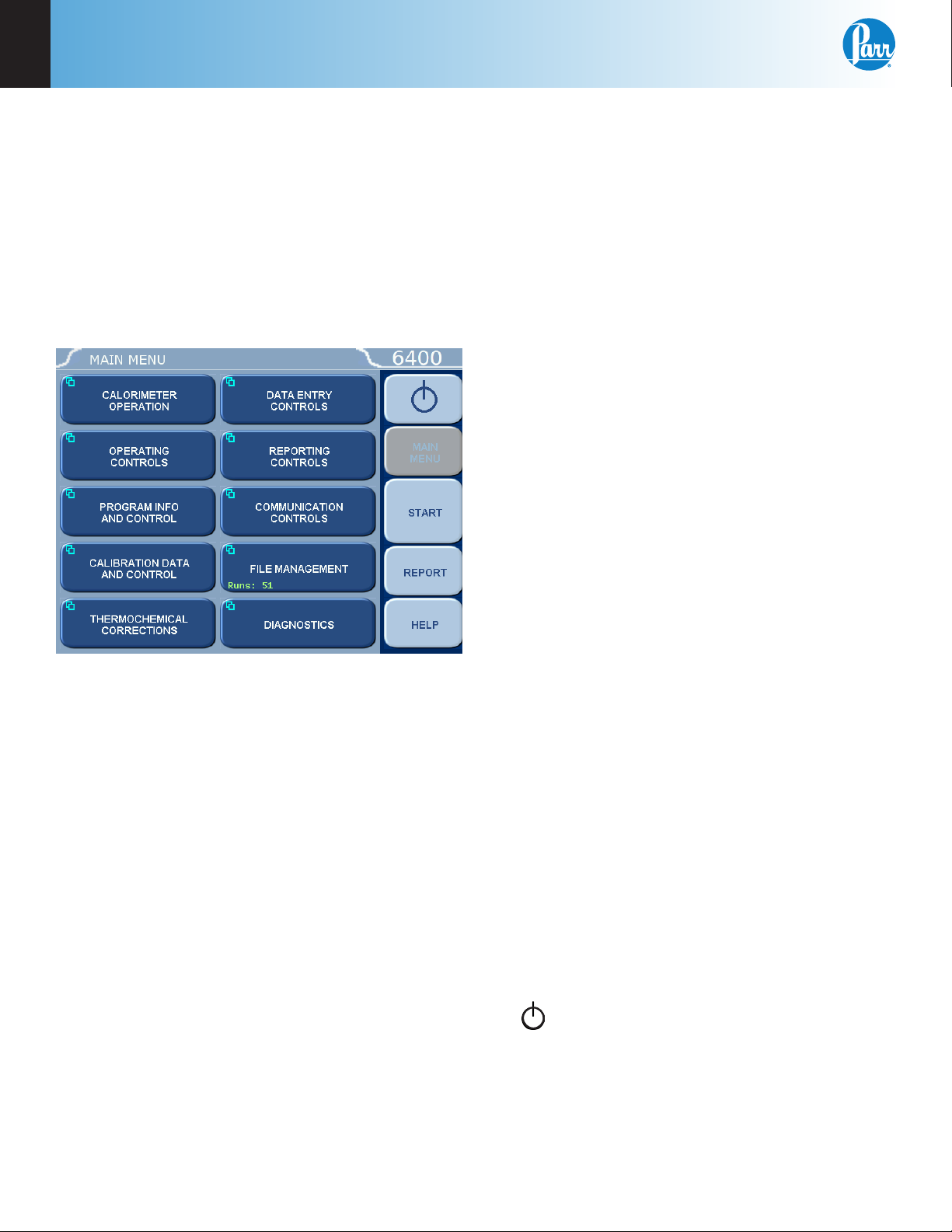
Menu System
All configurations and operations are handled by
a menu-driven system operated from the bright
touch screen display. The settings and controls are
organized into ten main sections as displayed on the
MAIN MENU.
Note: Keys with a “double box” in the upper
left hand corner lead to sub-menus.
Menu Keys
The controls that change the data field information
in the menus will be one of the following:
1. Toggles. These data elds contain ON/OFF or
YES/NO choices. Simply touching the key on the
screen toggles the choice to the other option.
The current setting is displayed in the lower
right corner of the key.
2. Option Selection. These data fields contain a list
of options. Touching the key on the screen steps
the user through the available choices. The cur-
rent setting is displayed in the lower right corner
of the key.
3. Value Entry Fields. These data fields are used to
enter data into the Calorimeter. Touching the key
on the screen brings up a sub-menu with a key
pad or similar screen for entering the required
value. Some keys lead to multiple choices.
Always clear the current value before entering a
new value. Once entered the screen will return
to the previous menu and the new value will be
displayed in the lower right corner of the key.
4. Data Displays. Most of these keys display values
that have been calculated by the calorimeter
and are informational only. Certain ones can be
overridden by the user entering a desired value
through a sub-menu. The value is displayed in
the lower right corner of the key.
Note: Some keys will respond with an op-
portunity for the user to confirm the speci-
fied action to minimize accidental disruptions
to the program and/or stored data.
Control Keys
There are five control keys which always appear
in the right column of the primary displays. These
keys are unavailable when they are gray instead of
white.
1. Escape. This key is used to go up one level in
the menu structure.
2. Main Menu. This key is used to return to the
main menu touch screen from anywhere in the
menu structure.
3. Start. This key is used to start a test.
4. Abort. When a test is running the Start button
changes to Abort. When pressed it will terminate
the current test or pre-test.
5. Report. This key is used to access the test re-
sults stored in the calorimeter, to enter thermo-
chemical corrections, and to initiate a report on
the display or printer.
6. Help. This key is used to access help screens
related to the menu currently displayed on the
touch screen.
7. This key appears in the Escape key loca-
tion when the main menu is displayed. This key
is used to shut down the calorimeter program
before turning off the power.

Operation
6400
3
www.parrinst.com
19
Programming
The program in the 6400 Calorimeter can be exten-
sively modified to tailor the unit to a wide variety
of operating conditions, reporting units, laboratory
techniques, available accessories and communica-
tion modes. In addition, the calculations, thermo-
chemical corrections and reporting modes can be
modified to conform to a number of standard test
methods and procedures. Numerous provisions are
included to permit the use of other reagent concen-
trations, techniques, combustion aids and short cuts
appropriate for the user’s work.
Note: Changes to the program are made
by use of the menu structure. Any of these
items can be individually entered at any time
to revise the operating program.
Default Settings
Units are pre programmed with default settings.
See Table 15-1 for a listing of the factory default
settings. A more in-depth explanation of these pa-
rameters is found on the corresponding parameter
group help pages. These default settings remain
in effect until changed by the user. Should the user
ever wish to return to the factory default settings, go
to the Program Info and Control Menu, User/Factory
Settings, touch Reload Factory Default Settings and
YES. Non-volatile memory is provided to retain any
and all operator initiated program changes; even
if power is interrupted or the unit is turned off. If
the unit experiences an intentional or unintentional
“Cold Restart”, the controller will return to the last
known settings.
The default parameters of the 6400 Calorimeter can
be changed to guarantee that the calorimeter, when
cold restarted, will always be in the desired configu-
ration before beginning a series of tests. Users who
wish to permanently revise their default settings
may do so using the following procedure:
• Establish the operating parameters to be stored
as the user default settings.
• Go to the Program Info and Control Menu, User/
Factory Settings, User Setup ID, and enter the
desired User Setup ID.
• Select Save User Default Settings
To re-load the user default setting, go to the Pro-
gram Info and Control Page, User/Factory Settings,
Re-load User Default Settings, and YES.
Sample Preparation
Sample Size
To stay within safe limits, the bomb should never be
charged with a sample which will release more than
8000 calories when burned in oxygen. The initial
oxygen pressure is set at 30 atmospheres (450 psig).
This generally limits the mass of the combustible
charge (sample plus benzoic acid, gelatin, firing oil
or any combustion aid) to not more than 1.1 grams.
To avoid damage to the bomb and calorimeter,
and possible injury to the operator, it should be
a standing rule in each laboratory that the bomb
must never be charged with more than 1.5 grams of
combustible material.
When starting tests with new or unfamiliar materi-
als, it is always best to use samples of less than 0.7
grams with the possibility of increasing the amount if
preliminary tests indicate no abnormal behavior and
the sample will not exceed the 8000 calorie limit.
Samples containing sulfur should contain no more
than 50 mg of sulfur and liberate at least 5000
calories.
Samples containing chlorine should be spiked to
insure that sample contains no more than 100 mg of
chlorine and liberates at least 5000 calories
Particle Size and Moisture Content
Solid samples burn best in an oxygen bomb when
reduced to 60 mesh, or smaller, and compressed
into a pellet with a 2811 Parr Pellet Press. Large par-
ticles may not burn completely and small particles
are easily swept out of the capsule by turbulent
gases during rapid combustion.
Note: Particle size is important because it
influences the reaction rate. Compression
into a pellet is recommended because the
pressure developed during combustion can
be reduced as much as 40% when compared
to the combustion of the material in the
powder form. In addition to giving controlled
burn rates, the formation of pellets from
sample material keeps the sample in the fuel
capsule during combustion.
Materials, such as coal, burn well in the as-received
or air-dry condition, but do not burn completely dry
samples. A certain amount of moisture is desirable
in order to control the burning rate. Moisture con-
tent up to 20% can be tolerated in many cases, but
the optimum moisture is best determined by trial

3
Operation
Parr Instrument Company
20
combustions. If moisture is to be added to retard
the combustion rate, drop the water directly onto
the loose sample or onto a pellet after the sample
has been weighed. Then let the sample stand to
obtain uniform distribution. Low volatile samples
with high water content, such as urine or blood,
can be burned in an open capsule by absorbing the
liquid on filter paper pulp or by adding a combus-
tion aid, such as ethylene glycol.
Sample Types
Because of the difference in combustion char-
acteristics of the many different materials which
may be burned in an oxygen bomb, it is difficult to
give specific directions which will assure complete
combustions for all samples.
The following fundamental conditions should be
considered when burning samples:
• Some part of the sample must be heated to its
ignition temperature to start the combustion
and, in burning, it must liberate sufficient heat
to support its own combustion regardless of the
chilling effect of the adjacent metal parts.
• The combustion must produce sufficient tur-
bulence within the bomb to bring oxygen into
the fuel cup for burning the last traces of the
sample.
• A loose or powdery condition of the sample
which will permit unburned particles to be
ejected during a violent combustion.
• The use of a sample which contains coarse par-
ticles will not burn readily. Coal particles which
are too large to pass a 60 mesh screen may not
burn completely.
• The use of a sample pellet which has been made
too hard or too soft can cause spalling and the
ejection of unburned fragments.
• The bottom of the cup should always be at least
one-half inch above the bottom of the bomb or
above the liquid level in the bomb to prevent
thermal quenching.
• If the moisture, ash and other non combustible
material in the sample totals approximately 20%
or more of the charge, it may be difficult to obtain
complete combustion. This condition can be rem-
edied by adding a small amount of benzoic acid or
other combustion aid.
Foodstuffs and Cellulosic Materials
Fibrous and fluffy materials generally require one of
three modes for controlling the burn rate. Fibrous
materials do not pelletize readily and generally
require either moisture content or a combustion aid
such as mineral oil to retard the burn rate and avoid
development of high pressures. Partial drying may
be necessary if the moisture content is too high to
obtain ignition, but if the sample is heat sensitive
and cannot be dried, a water soluble combustion aid
such as ethylene glycol can be added to promote
ignition. Material such as Napthalene should not be
burned in loose powder form but should be formed
into a pellet.
Coarse Samples
In most cases it may be necessary to burn coarse
samples without size reduction since grinding or
drying may introduce unwanted changes. There
is no objection to this if the coarse sample will
ignite and burn completely. Whole wheat grains
and coarse charcoal chunks are typical of materials
which will burn satisfactorily without grinding and
without additives or a special procedure.
Corrosive Samples
The 1138 bomb is made from alloy 20; a special
niobium stabilized stainless steel selected for its
resistance to the mixed nitric and sulfuric acids pro-
duced during the combustion process. The 1138CL
is made from the halogen resistant Hastelloy G30™.
Hastelloy 30™ is an alloy rich in cobalt and molyb-
denum and is able to resist the corrosive effects
of free chlorine and halogen acids produced when
burning samples with significant chlorine content.
While no alloy will completely resist the corrosive
atmospheres produced when burning samples
containing halogen compounds; users who intend
to test these materials are urged to select the 1138CL
Bomb. These bombs are 250 mL in volume and are
rated to a maximum working pressure of 2000 psi.
The bombs are hydrostatically tested to 3000 psi
and the sample range is ~1g or 5000 – 8000 calories.
Explosives and High Energy Fuels
Materials which release large volumes of gas
which detonate with explosive force or burn with
unusually high energy levels, should not be tested
in this calorimeter. Rather, they should be tested
in a model 6100 or 6200 Calorimeter which can be
equipped with an 1104 High Strength Oxygen Bomb
designed specifically for these types of samples.
Operation
6400
3
www.parrinst.com
21
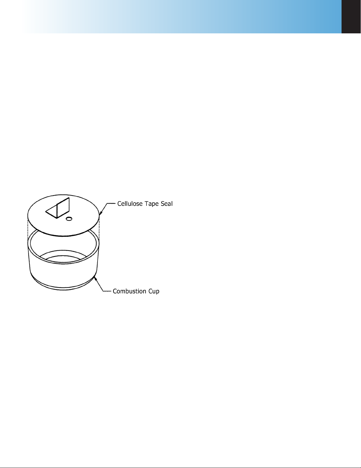
Volatile Sample Holders
Volatile samples are defined as one with an initial
boiling point below 180 ºC. Volatile samples can be
handled in a Parr 43AS Alloy Capsule which has a
sturdy wall with a flat top rim. These holders can be
sealed with a disc of plastic adhesive tape prepared
by stretching tape across the top of the cup and
trimming the excess with a sharp knife. The seal
obtained after pressing this disc firmly against the
rim of the cup with a flat blade will be adequate
for most volatile samples. The tape used for this
purpose should be free of chlorine and as low in
sulfur as possible. Borden Mystic Tape, No. M-169-C
or 3M Transparent Tape, No. 610, are recommended
for this purpose. The 3M Transparent Tape can be
ordered through Parr, Part No. 517A.
Figure 3-1
Volatile Sample Technique
The weight of the tape disc must be determined
separately and a correction applied for any elements
in the tape which might interfere with the determi-
nation. The approximate Heat of Combustion of
the tape is 6300 cal/g. An actual amount should be
determined by running a blank test with tape alone
using a sample weighing 1.0 gram. The compensa-
tion for heat of tape may be done through the spike
option; see Spike Controls, Heat of Combustion of
Spike.
Note: Tape should always be stored in a
sealed container to minimize changes in its
moisture and solvent content.
Use the following procedure when filling and han-
dling any of these tape-sealed sample holders:
1. Weigh the empty cup or capsule; then cover the
top with tape, trim with a knife and press the
trimmed edge firmly against the metal rim. Also
cut and attach a small flag to the disc (see Figure
3-1).
2. Puncture the tape at a point below the flag, then
re-weigh the empty cup with its tape cover.
3. Add the sample with a hypodermic syringe;
close the opening with the flag and re-weigh the
filled cup.
4. Set the cup in the capsule holder and arrange
the auxiliary fuse so that it touches the center of
the tape disc.
5. Just before starting the test, prick the disc with
a sharp needle to make a small opening which
is needed to prevent collapse of the disc when
pressure is applied.
6. Fill the bomb with the usual oxygen charging
pressure.
7. The calorimeter will fire the bomb and complete
the test in the usual manner.
Combustion Aids
Some samples may be difficult to ignite or they may
burn so slowly that the particles become chilled
below the ignition point before complete combus-
tion is obtained. In such cases white oil or other
suitable material of known purity can be mixed with
the sample. Ethylene glycol, butyl alcohol or decalin
may be used for this purpose.
Note: It must be remembered, that a com-
bustion aid adds to the total energy released
in the bomb and the amount of sample may
have to be reduced to compensate for the
added charge.
When benzoic acid is combusted for standardization
runs, it should be in the form of a pellet to avoid
possible damage to the bomb which might result
from rapid combustion of the loose powder.

3
Operation
Parr Instrument Company
22
Combustion Capsules
Non-volatile samples to be tested in Parr oxygen
bombs are weighed and burned in shallow capsules
measuring approximately 1” diameter and 7/16”
deep. These are available in stainless steel, fused
silica, fused quartz, and platinum alloyed with
3-1/2% rhodium.
Stainless steel capsules (43AS) are furnished with
each calorimeter. The stainless steel capsules will
acquire a dull gray finish after repeated use in an
oxygen bomb due to the formation of a hard, protec-
tive oxide film. This dull finish not only protects the
capsule, but it also promotes combustion and makes
it easier to burn the last traces of the sample. New
capsules are heated in a muffle furnace at 500 ºC for
24 hours to develop this protective coating uniform-
ly on all surfaces. This treatment should be repeated
after a capsule has been polished with an abrasive to
remove any ash or other surface deposits. Heating in
a muffle is also a good way to destroy any traces of
carbon or combustible matter which might remain
in the capsule from a previous test. Capsules should
be monitored for wear. Do not use the capsule if the
wall or base thickness is less than 0.025”.
Note: After heating, place the capsules in
a clean container and handle them only
with forceps when they are removed to be
weighed on an analytical balance.
When combusting samples that contain metal
particles such as aluminum or magnesium, the non-
metallic 43A3 Fused Silica or 43A3KQ Fused Quartz
Capsule is required.
When superior corrosion resistance is needed, the
43A5 Platinum Rhodium Capsule or 43A3KQ Fused
Quartz is required.
Test Process
Loading the sample
Prepare and weigh the sample to 0.0001g. Gently
tap capsules that contain powdered samples to
compact the material. (Pellets are easier to handle
than loose samples and they burn slower in the
bomb, thereby reducing the chances for incomplete
combustion).
Carefully place the
capsule into the capsule
holder. A cotton thread
(845DD2) is used as an
auxiliary fuse to ignite
the sample. Remove any
moisture from the heat-
ing wire prior to attach-
ing the cotton thread.
Four inches (10 cm) of
thread is recommended
for this auxiliary thread
which is looped over the
heating wire, doubled
on itself, twisted to form
a single strand and fed
into the sample cup to
lay on the sample. When
contact is made through
the heating wire, the
thread will ignite, drop into the sample cup and
ignite the sample. One spool of thread, part number
845DD, is 563 yards. Part number 845DD2 contains
approximately 1000 pieces of thread pre-cut to 4
inches (10 cm).
Closing the bomb
Care must be taken not to disturb the sample when
moving the bomb head from the support stand to
the bomb cylinder in the calorimeter. Check the
sealing ring to be sure that it is in good condition
and moisten it with a bit of water so that it will slide
freely into the cylinder.
Notice that the bomb head grounding lug extends
beyond the outside diameter of the bomb head. A
slot for this lug is cut into the top of the calorimeter
bucket which holds the bomb cylinder. Position
this lug approximately 20 degrees to the operators
right and slide the head into the cylinder and push it
down as far as it will go. Now rotate the bomb head
20 degrees to the left until the lug contacts the left
edge of the cut out and is pointed to the front of the
calorimeter.
Figure 3-2
Cotton Thread Assembly
Operation
6400
3
www.parrinst.com
23
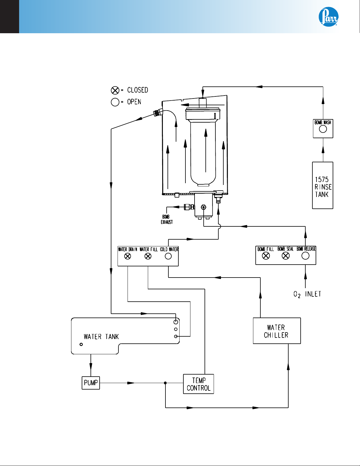
Fill Cycle
Once the calorimeter is started and the cover is closed, the fill sequence begins.
Figure 3-3
Bucket Fill Flow Diagram
1. The calorimeter checks the bomb ignition circuitry for continuity.
2. The water fill solenoid opens and water is pumped from the internal tank into and through the bucket that
surrounds the bomb. Overflow from the bucket is returned to the closed water tank. Because the jacket and
bucket are both filled with water from the closed water tank, initial equilibrium will be reached quickly.
3. The oxygen fill solenoid is opened and oxygen is added slowly to the bomb to bring its pressure to
approximately 30 atm.
3
Operation
Parr Instrument Company
24
Pre-Period
At the completion of the fill sequence, the pre-period begins.
Figure 3-4
Pre-Period/Post-Period Flow Diagram
1. The water fill solenoid valve closes and isolates the water in the bucket from the rest of the system.
Water within this bucket is circulated by the stirrer. Water continues to circulate from the closed water
system through the jacket surrounding the bucket.
2. The oxygen filling valve closes and the pressure in the filling line is vented. The automatic check valve at
the top of the bomb closes and isolates the bomb from the oxygen filling line.
3. The controller monitors the operating temperature until it confirms that the initial equilibrium has been
established.

Operation
6400
3
www.parrinst.com
25
Bomb Firing
Once the initial equilibrium is confirmed, the con-
troller initiates the firing sequence. There are no
changes to the circulation pattern, as shown in
Figure 3-4, from the pre-period through the bomb
firing and post-period. A warning of short beeps is
sounded indicating the bomb is about to be fired.
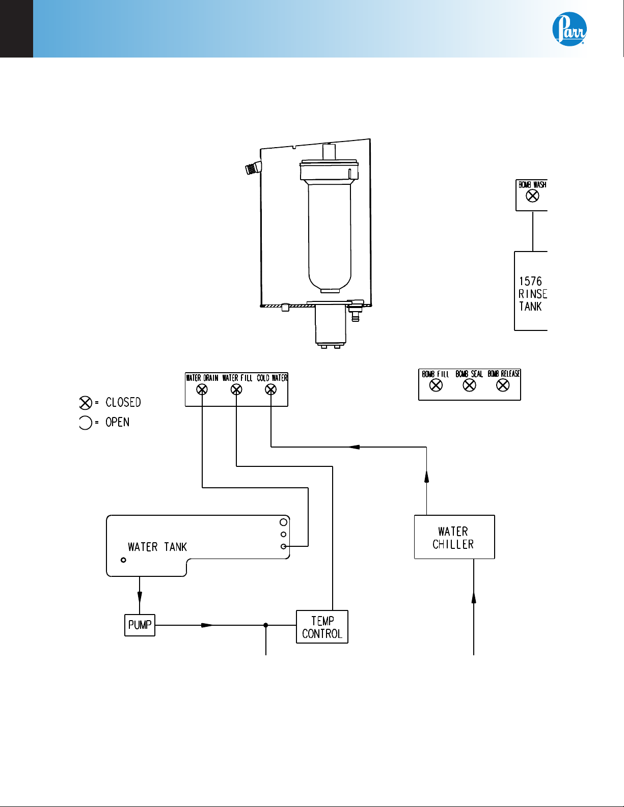
Post-Period
A minimal temperature rise will confirm that the
sample has ignited. After this verification, the post-
period begins. See Figure 3-4.
1. The controller monitors the temperature rise
and determines the final temperature rise by
either the dynamic or equilibrium criteria as
established by the user.
2. Once the final temperature rise is determined,
it is recorded with the test results.
3
Operation
Parr Instrument Company
26
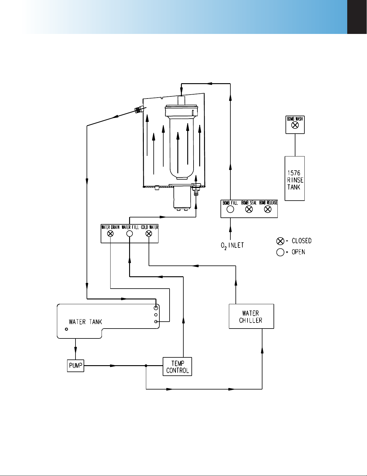
Cool/Rinse
At the completion of the post-period, the rinse and cool sequence begins.
Figure 3-5
Rinse & Cool Flow Diagram
1. Chilled water is circu-
lated through the bucket
to cool the bomb to the
starting temperature.
2. The release valve in the
bottom of the bomb is
opened and the residual
pressure is released
through the bomb ex-
haust line.
3. Once the excess oxygen
is vented, the bomb rinse
water from the rinse
water tank is admitted
through the bomb rinse
solenoid valve and the
check valve at the top
of the bomb. The bomb
rinse water is released to
the wash bottle.
Note: Several rinse
patterns may be con-
figured by the user to
meet various opera-
tional and analytical
requirements.
4. The bomb is filled one
more time with oxygen
to help flush
the water
residue
from the
interior of
the bomb.
Operation
6400
3
www.parrinst.com
27
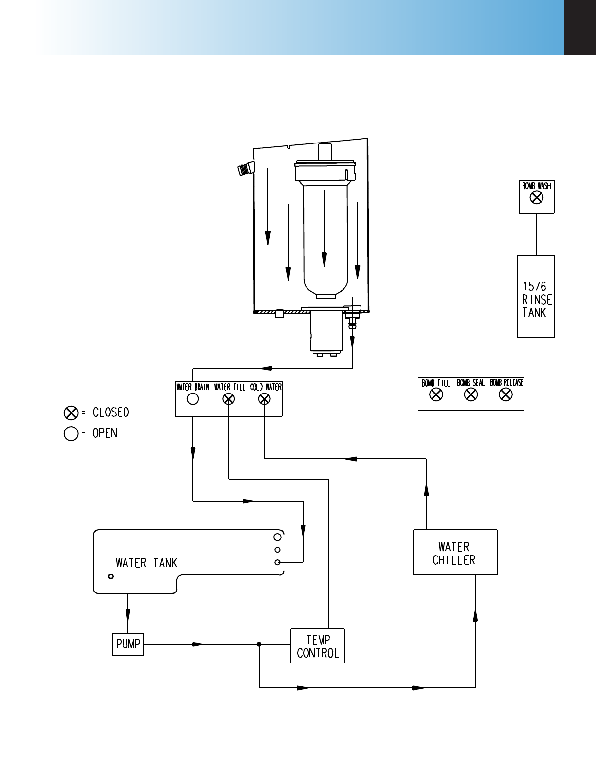
Drain
At the completion of the bomb rinse sequence, the drain sequence begins.
Figure 3-6
Drain Flow Diagram
The water in the bucket is drained out of the bucket and routed to the drain connection. Once the bucket is
drained, the calorimeter may be opened to remove the bomb head and load the next sample.
4
Menu Descriptions
Parr Instrument Company
28
chaPter 4
Menu Descriptions
Note: Keys which make global changes to
the setup of the calorimeter contain a YES or
NO response to make certain that the user
wishes to proceed. This two step entry is
intended to prevent inadvertent global pro-
gram changes.
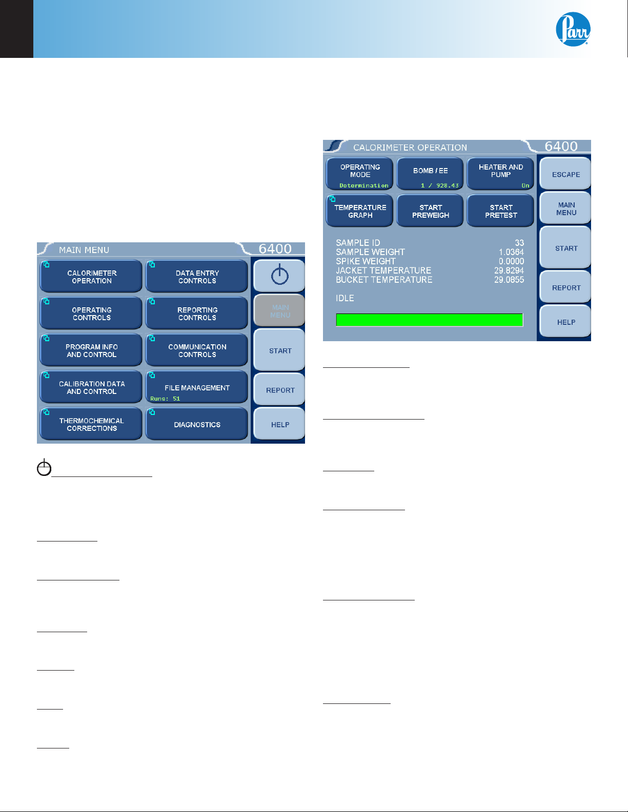
Main Menu
System Shutdown: This key appears in the
ESCAPE key location when the Main Menu is dis-
played. Pressing this button will prompt the user to
confirm a system shutdown.
Escape Key: Selecting the Escape key on any menu
will return you to the menu one level up.
Main Menu Key: Selecting the Main Menu key on
any menu will return you to the screen pictured on
the right of this page.
Start Key: Press the Start key to begin any Determi-
nation or Standardization run.
Report: Press the Report key to begin the reporting
process.
Help: Press the Help key on any screen to display
the explanation text for that screen.
Abort: This key appears in the Start key location
while a test or pretest is running. Pressing this key
will abort the test or pretest in progress.
Calorimeter Operation Menu
The Calorimeter will normally be operated from the
Calorimeter Operation Menu, although tests can
always be started from any menu screen.
Operating Mode: Sets the operating mode by
toggling between Standardization (for instrument
calibration) and Determination (for test runs).
Temperature Graph: Press this key to display a real-
time plot of the bucket and/or jacket temperature on
the Temperature vs. Time Plot screen.
Bomb/EE: Used to identify the bomb presently
installed in the Calorimeter and its EE value.
Start Preweigh: This key is used to start the sample
pre-weigh process. The user is presented with or
prompted for a sample ID. Next, the user is asked to
key in the associated sample mass or alternatively
the mass is retrieved from a connected balance or
network.
Heater and Pump: The heater and pump must only
be turned on after the calorimeter water tank is filled
with water.
Note: The heater and pump must be turned
ON to bring the jacket to the correct starting
temperature before testing can commence.
Start Pretest: This key is used to initiate a pretest
cycle. A pretest will cycle the calorimeter through
the ll and cool/rinse process. This function is used
to pre-condition the calorimeter.
Loading...