


 Loading...
205M
1108
Oxygen Combustion Vessel
Operating Instruction Manual

1108 Oxygen Combustion Vessel
Table of Contents
Preface
Scope — 3
Related Instructions — 3
Operating the 1108 Oxygen Combustion Vessel
Precautions — 4
Special Alloy Construction — 4
A Chlorine-Resistant Bomb — 4 1108B Oxygen Combustion Vessel — 4 Other Special Purpose Bombs — 4 Allowable Sample Size — 4 Attaching the Fuse — 5
Liquids in the Bomb — 5
Closing the Bomb — 5
Filling the Bomb — 6
Firing the Bomb — 6
Recovering the Combustion Products — 7 An Optional Recovery Procedure — 7
Samples and Sample Holders
Particle Size and Moisture Content — 8
Combustion Aids — 8
Sample Pellets — 8
Combustion Capsules — 8
Foodstuffs and Cellulosic Materials — 9
Coarse Samples — 9
Corrosive Samples — 9
Liquid Samples — 9
Gelatin Capsules — 9
Tape-Sealed Sample Holders — 10
Heavy Oils — 10
Explosives and High Energy Fuels — 10
Operating Suggestions
Poor Combustion — 11
Oxygen Charging Pressure — 11
Maintenance and Safety Instructions
Vessel Maintenance — 12
Vessel Repairs and ProofTests — 13
1108 Maintenance Checklist — 14
Parts
1108 Parts Diagram Key — 16
Parts for the 1108 Oxygen Combustion Vessel — 17 Parts for the 2901 Ignition Unit — 18
Parts for the 1825 Oxygen Filling Connection — 19
2 |
P a r r I n s t r u m e n t C o m p a n y |

1108 Oxygen Combustion Vessel
Preface
Scope
These instructions cover the procedures to be followed when using a Parr 1108 Oxygen Combustion Vessel to determine calorific values of solid or liquid combustible material in a Parr calorimeter, or when using an 1108 vessel in a 1901 Oxygen Vessel Apparatus to prepare solid or liquid samples for chemical analysis.The user should study these instructions carefully in order to obtain a complete understanding of the capabilities and limitations of an 1108 Oxygen Combustion Vessel, and to be well aware of the precautions to be observed in its operation. Calorimeter operations and the operation of various oxygen combustion vessel accessories are described in separate instruction manuals listed below, copies of which are available upon request.
Related Instructions
No. Description
201M Limited Warranty
207M Analytical Methods for Oxygen Bombs
230M Safety in the Operation of Laboratory
and Pressure Vessels
483M Introduction to Bomb Calorimetry
Note About Nomenclature:
Historically, burning a sample enclosed in a high pressure oxygen environment is known as Oxygen Bomb Calorimetry and the vessel containing the sample is known as an Oxygen Bomb. The terms bomb and vessel are used interchangeably.
Customer Service
Questions concerning the installation or operation of this instrument can be answered by the Parr Customer Service Department:
1-309-762-7716 • 1-800-872-7720 • Fax: 1-309-762-9453
E-mail: parr@parrinst.com • http://www.parrinst.com
w w w . p a r r i n s t . c o m |
3 |

1108 Oxygen Combustion Vessel
Operating the 1108 Oxygen
Combustion Vessel
Precautions
Combustion with oxygen in a sealed bomb is a very effective and reliable method for releasing all heat energy obtainable from a sample and for preparing hydrocarbon compounds and carbonaceous materials for analysis, but there are certain precautions which must always be observed when using this equipment. In particular:
•Do not overcharge the bomb with too much sample or with a sample which might react with explosive violence.
•Do not overcharge the bomb with too much oxygen.The initial charging pressure should not exceed 40 atm (590 psig).
•Do not fire the bomb alone on an open bench without providing a protective cooling medium. The bomb should be completely submerged in water during firing.
•Do not fire the bomb if gas bubbles are released from any point on the bomb when it is submerged in water.
•Do not ignite a volatile sample without using one of the sealed sample holders described on pages 8-9.
•Stand away from the bomb during and do not handle the bomb for at least 6 minutes after firing.
•Keep the bomb in good condition at all times. Any parts that show signs of weakness or deterioration must be replaced promptly.
•Read the maintenance and safety instructions beginning on page 12 before starting to use the bomb, and urge all operating personnel to reread these instructions often.
•Screw caps and cylinders are stamped so that each cylinder and screw cap can be identified as a matched set. We recommend that you maintain the match of cylinders and screw caps for your safety and ease of use.
Special Alloy Construction
The standard 1108 Oxygen Combustion Vessel is made of a special columbium-stabilized stainless steel selected for it’s excellent resistance to the mixed nitric and sulfuric acids generated in a combustion. It is a superior alloy which will withstand the conditions generated in almost all fuel testing applications, yet neither it nor any other stainless steel will resist the corrosive atmospheres produced when
4 |
P a r r I n s t r u m e n t C o m p a n y |
burning samples containing halogen compounds. For these applications, Parr offers the 1108CL Oxygen Combustion Vessel described below. It should be noted that all instructions for the 1108 apply equally to the 1108CL as well.
A Chlorine-Resistant Bomb
The 1108CL Combustion Vessel is the same as the standard 1108 model, but with a head and cylinder made of an alloy with superior corrosion resistance to the free chlorine and halogen acids released when burning chlorinated samples. Users who analyze waste materials and combustible solvents are urged to select the 1108CL Combustion Ves-
sel instead of 1108 for its longer service life under extreme corrosive conditions. Bomb maintenance is also improved. In most cases, 1108CL returned to the factory for scheduled maintenance can be
restored to optimum finish by repolishing instead of having to rebore the cylinder to remove pits.
1108B Oxygen Combustion Vessel
The 1108B and 1108BCL Combustion Vessels are identical to the 1108 and 1108CL models except for the screw cap and cylinder. The 1108B and 1108BCL have a heavy duty screw cap allowing for higher energy release per sample. The cylinder has been adapted to comply with Indian Standard IS 1350.
Other Special Purpose Bombs
Although the 1108 and 1108CL Combustion Vessels will handle a broad range of test samples, Parr also offers other special purpose combustion bombs, including: a high pressure bomb for explosives, an oversize bomb for large samples and a semi-micro bomb for small samples. Separate operating instructions are issued for these special bombs.
Allowable Sample Size
To stay within safe limits, the bomb should never be charged with a sample which will release more than 8000 calories (1108) or 10,000 calories (1108B) when burned in oxygen, and the initial oxygen pressure should never exceed 40 atmospheres (590 psig). This generally limits the mass of the combustible charge (sample plus benzoic acid, gelatin, firing oil or any combustion aid) to not more than 1.1 grams. When starting tests with new or unfamiliar materials it is always best to use samples of less than 0.7 of a gram, with the possibility of increasing the amount if preliminary tests indicate no abnormal behavior. To avoid damage to the bomb and possible injury to the operator, it should be a standing rule in each laboratory that the bomb must never be charged with more than 1.5 grams of combustible material.
1108 Oxygen Combustion Vessel
45C10 Fuse Wire
|
Set the bomb head on the A38A |
|
|
support stand when attaching the |
|
|
fuse and arranging the sample. |
|
|
To attach the fuse: raise the cap, |
|
|
insert the wire through the eye- |
|
|
let, then pull the cap downward |
|
A38A Head Support & Stand |
to complete the assembly. |
Fuse Wire Fastened BetweenTwo Electrodes |
|
Attaching the Fuse
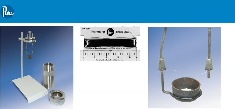
Set the bomb head on an A38A support stand and fasten a 10 cm length of fuse wire between the two electrodes. Parr 45C10 nickel alloy wire is used for most tests, with platinum wire offered as an alternate for certain special procedures.The 45C10 wire is furnished on cards from which uniform 10 cm lengths can be cut without further measurement.
Quick-grip electrodes now installed in all new 1108 Oxygen Combustion Vessels eliminate most of the threading and twisting formerly required when binding the wire to plain electrodes.To attach the fuse to quick-grip electrodes, insert the ends of the wire into the eyelet at the end of each stem and push the cap downward to pinch the wire into place. No further threading or twisting is required.The procedure for binding the fuse to the 4A and 5A plain electrodes in older Parr vessels is illustrated in the instruc-
tion manual furnished with the original equipment. For convenience, it is recommended that the user purchase and install new 4A10 and 5A10 quick-grip electrodes as replacements for the 4A and 5A styles in older equipment.
Place the fuel capsule with its weighed sample in the electrode loop and bend the wire downward toward the surface of the charge as shown above. It is not necessary to submerge the wire in a powdered sample. In fact, better combustions will usually be obtained if the loop of the fuse is set slightly above the surface. When using pelleted samples, bend the wire so that the loop bears against the top of the pellet firmly enough to keep it from sliding against the side of the capsule. It is also good practice to tilt the capsule slightly to one side so that the flame emerging from it will not impinge directly on the tip of the straight electrode.
Liquids in the Bomb
Most combustion procedures call for a small amount of liquid to be placed in the bottom of the bomb as a sequestering agent and absorbent. If the amount and type of liquid are not otherwise specified, add 1.0 mL of distilled or deionized water from a pipet.
Closing the Bomb
Care must be taken not to disturb the sample when moving the bomb head from the support stand to the bomb cylinder. Check the sealing ring to be sure that it is in good condition and moisten it with a bit of water so that it will slide freely into the cylinder; then slide the head into the cylinder and push it down as far as it will go. For easy insertion, push the head straight down without twisting and leave the gas release valve open during this operation. When working with older bombs which have a removable compression ring, be sure that the 104A2 ring is in place above the gasket before attaching the screw cap. Current model A416A3 Head Assemblies do not require a separate compression ring. Set the screw cap on the cylinder and turn it down firmly by hand to a solid stop. When properly closed, no threads on the cylinder should be exposed. If the screw cap tends to bind to the cylinder at this point, indicating that it might be difficult to open the bomb after it has been fired, turn the screw cap back slightly – but only a few degrees – enough to release the binding, since the bottom thread must remain fully engaged. It is not necessary to use a wrench or spanner on the screw cap. Hand tightening should be sufficient to secure a tight seal.
w w w . p a r r i n s t . c o m |
5 |

1108 Oxygen Combustion Vessel
Filling the Bomb
The instructions below describe a manual system using the 1825 Oxygen Filling Connection furnished with other Parr apparatus.
Oxygen for the bomb can be drawn from a standard commercial oxygen tank.
Unscrew the protective cap from the tank and inspect the threads on the valve outlet to be sure they are clean and in good condition. Place the ball end of the connection into the outlet socket and draw up the union nut tightly with a wrench, keeping the 0-55 atm gage in an upright position.
1825 Oxygen Filling
Connection
The pressure connection to the bomb is made with a slip connector on the oxygen hose which slides over the gas inlet fitting on the bomb head. Slide the connector onto the inlet valve body and push it down as far as it will go. If it does not slide easily, a drop of water spread around the inlet valve will lubricate the sealing rings. Older bombs use a threaded connector with a knurled coupling which must be turned finger tight.
Close the outlet valve on the bomb head; then open or “crack” the oxygen tank valve not more than one-quarter turn. Open the filling connection control valve slowly and watch the gage as the bomb pressure rises to the desired filling pressure (usually 30 atm., but never more than 40 atm.); then close the control valve. Release the residual pressure in the filling hose by pushing downward on the lever attached to the relief valve.The gage should now return to zero.The bomb inlet check valve will close automatically when the oxygen supply is shut off, leaving the bomb filled to the highest pressure indicated on the 0-55 atm. Gage. If the pressure drops slowly and a large amount of gas escapes when the pressure relief valve is opened, the check valve in the bomb head is not operating properly.This trouble will have to be corrected before the bomb can be used. If too much oxygen should accidentally be introduced into the bomb, DO NOT proceed with the combustion. Detach the filling connection; exhaust the bomb; remove the head and reweigh the sample before repeating the filling operation.
6 |
P a r r I n s t r u m e n t C o m p a n y |
Firing the Bomb
The electric current for firing the bomb should be drawn from a Parr 2901EB Ignition Unit connected to an 115V
50/60Hz grounded electrical outlet. (For 230V
50/60Hz use a 2901EE
Ignition Unit). Connect one of the lead wires from the calorimeter
to the 10 cm binding
post on the ignition unit 2901 Ignition Unit and the 2nd wire to the
middle or “common” terminal.
When using the bomb in a calorimeter, insert the 421A lifting handle into the two holes in the side of the screw cap and lower the bomb partially into the calorimeter water bucket. Press the banana plugs on the two ignition wires firmly into the terminal sockets on the bomb head before the head is completely immersed in the water. After connecting the wires, lower the bomb into the bucket with its feet spanning the circular boss in the bottom of the bucket. Remove the lifting handle and shake off any
drops of water back into the bucket. Be careful not to remove any water from the bucket with the fingers. When using the bomb alone for analytical purposes it should be connected to the ignition unit as described above and held submerged in an A387A or similar water bath during firing.
In all operations, check the bomb for leaks before firing. If any gas leakage is indicated, no matter how slight, DO NOT FIRETHE BOMB. Instead remove it from the water bath; release the pressure and eliminate the leak before proceeding with combustion test. If no leakage is indicated, adjust the water flow rate so that the bomb will be covered by a continuous flow of cold water during the firing period, then stand back and press the firing button on the ignition unit to fire the charge.
Caution: Do not have the head, hands or any parts of the body directly over the bomb during the firing period and do not go near the bomb for at least 20 seconds after the firing.
Loading...