


NO. 586M
Parr Instrument Company
6300
Oxygen Bomb Calorimeter
Operating Instruction Manual
For models produced after October 2010

6300
PREFACE — 7
Scope — 7
Explanation of Symbols — 8
Safety Information — 8
Intended Usage — 8
Cleaning & Maintenance — 8
General Specifications — 9
Environmental Conditions — 9
Getting Started — 9
CHAPTER 1
CONCEPT OF OPERATION — 11
A Highly Automated Procedure — 11
New Convenience and New Technology — 11
Isoperibol Operation — 11
Dynamic Operation — 11
Full Microprocessor Based Process Control — 12
Full Microprocessor Based Data Acquisition and
Handling — 12
Flexible Programming — 12
CHAPTER 2
INSTALLATION — 13
Required Consumables, Utilities and Power
Requirements — 13
Installing the Calorimeter — 13
6300 Calorimeter External Plumbing — 17
CHAPTER 3
INSTRUMENT DESCRIPTION — 21
Types of Controls — 21
Menu Keys — 21
Control Keys — 21
CHAPTER 4
PROGRAM INSTALLATION & CONTROL — 23
Software Installation — 23
Default Settings — 23
Revising Default Settings — 23
CHAPTER 5
OPERATING INSTRUCTIONS — 27
To Begin a Test — 27
Operating the Oxygen Bomb — 27
Allowable Sample Size — 29
Attaching the Cotton Thread — 29
Closing the Bomb — 31
Fill Cycle — 31
Pre-Period — 31
Bomb Firing — 31
Post-Period — 33
Cool/Rinse — 33
Drain — 33
Samples — 35
TABLE OF CONTENTS
Combustion Aids — 35
Oxygen Charging Pressure — 35
Combustion Capsules — 35
Foodstuffs and Cellulosic Materials — 36
Coarse Samples — 36
Corrosive Samples — 36
Explosives and High Energy Fuels — 36
Volatile Sample Holders — 36
Poor Combustion — 37
CHAPTER 6
CORRECTIONS & FINAL REPORTS — 39
Entering Corrections and Obtaining the Final Report — 39
Manual Entry — 39
Fixed Corrections — 39
CHAPTER 7
REPORTING INSTRUCTIONS — 41
Report Option Section — 41
Report Generation — 41
Net Heat of Combustion — 42
CHAPTER 8
FILE MANAGEMENT — 43
Clearing Memory — 43
Removable SD Memory — 43
CHAPTER 9
MAINTENANCE & TROUBLESHOOTING — 45
Routine Maintenance — 45
6300 Maintenance Checklist — 47 Inspection of Critical Sealing Surfaces — 48 Bomb Exhaust Troubleshooting — 48 Jacket Fill and Cooling Problems — 50 Bomb Removal and Replacement — 51 6300 Calorimeter Error List — 51
APPENDIX A
MENU OPERATING INSTRUCTIONS — 53
Main Menu — 53
Calorimeter Operation Menu — 53 Temperature vs. Time Plot — 54 Temperature Plot Setup Menu — 54 Operating Controls Menu — 55
Program Information and Control Menu — 57 Calibration and Data Controls Menu — 58 Thermochemical Calculations Menu — 60 Calculation Factors Menu — 62
Net Heat/Dry Heat Factors — 63
Data Entry Controls Menu — 63
Reporting Controls Menu — 65 Communication Controls Menu — 66 File Management — 67
Run Data File Manager — 68 Diagnostics Menu — 68
w w w . p a r r i n s t . c o m |
3 |

TABLE OF CONTENTS
APPENDIX B
CALCULATIONS — 71
Calculating the Heat of Combustion — 71 General Calculations — 71 Thermochemical Corrections — 71
Fuse Correction — 73
Acid and Sulfur Corrections — 73
ASTM Treatment for Acid and Sulfur — 74 ISO Calculations — 75
Spiking Samples — 75
Conversion to Net Heat of Combustion — 75
APPENDIX C
STANDARDIZATION — 77
Standardizing the Calorimeter — 77
Standard Materials — 77
Automatic Statistical Calculations — 77
APPENDIX D
COMMUNICATIONS INTERFACES — 81
USB Port — 81
Balance and Port Input Driver Specifications — 81
Mettler 011/012 Balance Interface — 81
Sartorius Balance Interface — 81
Generic Interface — 82
Ethernet Interface — 83
Samba Server Feature (Optional) — 84
Bar Code Port — 92
Network Data Services — 92
APPENDIX E
TECHNICAL SERVICE — 93
Return for Repair — 93
APPENDIX F
PARTS LISTS & DRAWINGS — 95
Principal Assemblies in Calorimeter — 95
A1250DD2 Controller Assembly — 96 A1251DD Oxygen Solenoid Assembly — 96 A1252DD Water Solenoid Assembly — 96 A1257DD Water Regulator Assembly — 97 A1258DD Temperature Control Assembly — 97 A1260DD Water Level Assembly — 97 A1264DD Air Can Assembly — 98
A1267DD Accessory/Installation Kit — 99 A1265DD Bucket and Stirrer Tube Assembly — 99 6300 Stirrer Motor and Drive — 100
A1255DD Bucket Stirrer Assembly — 100 A1266DD Cover Assembly — 100
6309B Spare Parts Kit — 101
1136 and 1136CL Oxygen Bomb — 103
1138 and 1138CL Oxygen Bomb — 105
4 |
P a r r I n s t r u m e n t C o m p a n y |
APPENDIX G
BOMB RINSE CONTAINER ASSEMBLY — 127
Overview — 127
Concept of Operation — 127
Connection — 127
Operation — 127
TABLES
Table B-1
Settings for ISO & BSI Methods — 74
Table C-1
Calorimeter Control Limit Values in J/g When Benzoic Acid is Used as a Test Sample — 78
Table C-2
Calorimeter Control Limit Values in cal/g When Benzoic Acid is Used as a Test Sample — 79
Table C-3
Calorimeter Control Limit Values in BTU/lb When Benzoic Acid is Used as a Test Sample — 80
Table D-1
6300 Data File Naming Convention — 82
Table D-2
6300 Calorimeter Run Data Template — 82
FIGURES
Figure 2-1
Swagelok Tube Fittings — 15
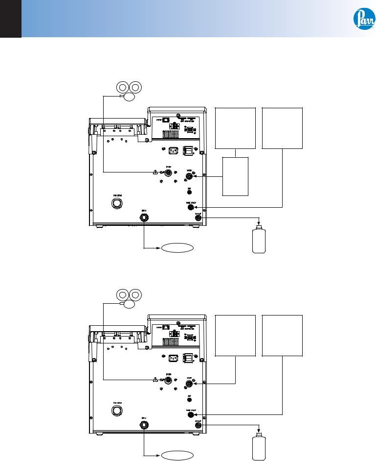
Figure 2-2
6300 Calorimeter Back Panel — 16
Figure 2-3
Closed Loop Configuration with 6520A — 17
Figure 2-4
Closed Loop Configuration with 1564 — 17
Figure 2-5
Open Loop Configuration with 1552 — 18
Figure 2-6
Open Loop Configuration — 18
Figure 4-1
6300 Factory Default Settings — 24
Figure 5-1
Fill Flow Diagram — 28
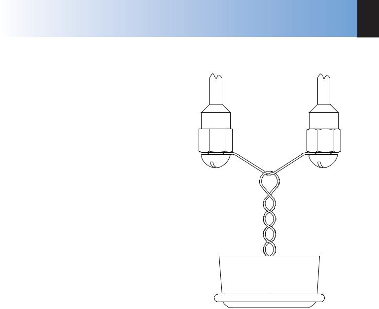
Figure 5-2
Cotton Thread Assembly — 29
Figure 5-3
Pre-period/Post-period — 30
Figure 5-4
Rinse & Cool Flow Diagram — 32
Figure 5-5
Drain Flow Diagram — 34
Figure 5-6
Combustion Capsule with Adhesive Tape Seal — 37
Figure F-1
Parts Diagram for the 1136 and 1136CL Oxygen
Bombs — 102

6300 |
TABLE OF CONTENTS |
FIGURES (CONTINUED)
Figure F-2
Parts Diagram for the 1138 and 1138CL Oxygen Bombs — 104
Figure F-3
6300 Oxygen Bomb Calorimeter Cutaway Right —
106
Figure F-4
6300 Oxygen Bomb Calorimeter Cutaway Left —
107
Figure F-5
6300 Oxygen Bomb Calorimeter Cover Open — 108
Figure F-6
A1250DD2 Control Schematic — 109
Figure F-7
A1251DD Oxygen Solenoid Assembly — 110
Figure F-8
A1200DD Internal Plumbing Diagram — 111
Figure F-9
A1252DD Water Solenoid Assembly — 112
Figure F-10
A1416DD Bomb Wash Pump Assembly and Fittings
— 113
Figure F-11
A1254DD Circulatory Pump Assembly — 114
Figure F-12
A1255DD Bucket Stirrer Assembly — 115
Figure F-13
A1256DD Water Assembly Tank — 116
Figure F-14
A1257DD Water Regulator Assembly — 117
Figure F-15
A1258DD Temperature Control Assembly — 118
Figure F-16
Cover Contact Pin Assembly — 119
Figure F-17
Stirrer Motor and Mount — 120
Figure F-18
A1260DD Water Level Control Assembly — 121
Figure F-19
A1265DD Bucket Assembly — 122
Figure F-20
6300 Air Can Assembly — 123
Figure F-21
A1450DD Bomb Head Assembly (1) — 124
Figure F-22
A1450DD Bomb Head Assembly (2) — 125
Figure G-1
Vessel Rinse Container — 128
w w w . p a r r i n s t . c o m |
5 |

TABLE OF CONTENTS
This page left blank intentionally.
6 |
P a r r I n s t r u m e n t C o m p a n y |

6300
PREFACE
SCOPE
This manual contains instructions for installing and operating the Parr 6300 Calorimeter. For ease of use, the manual is divided into nine chapters.
Concept of Operation
Installation
Instrument Description
Program Installation & Control
Operating Instructions
Corrections & Final Reports Reporting
Instructions
File Management
Maintenance & Troubleshooting
Subsections of these chapters are identified in the Table of Contents.
To assure successful installation and operation, the user must study all instructions carefully before starting to use the calorimeter to obtain an understanding of the capabilities of the equipment and the safety precautions to be observed in the operation.
Additional instructions concerning the installation and operation of various component parts and peripheral items used with the 6300 Calorimeter have been included and made a part of these instructions.
PREFACE
No. Description
201M Limited Warranty
207M Analytical Methods for Oxygen Bombs
230M Safety in the Operation of Laboratory and
Pressure Vessels
483M Introduction to Bomb Calorimetry
Additional instructions for the printer, cooler, and water handling systems are found in the respective package and should be made a part of this book.
Note:
The unit of heat used in this manual is the International Table (IT) calorie, which is equal to 4.1868 absolute joules.
Customer Service:
Questions concerning the installation or operation of this instrument can be answered by the Parr Customer Service Department:
1-309-762-7716 • 1-800-872-7720 • Fax: 1-309-762-9453 E-mail: parr@parrinst.com • http://www.parrinst.com
w w w . p a r r i n s t . c o m |
7 |
PREFACE
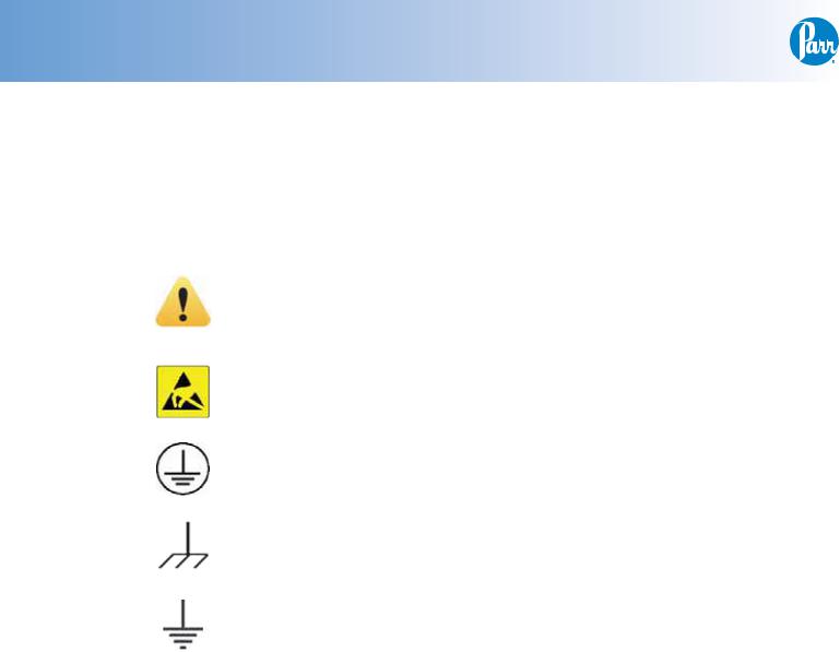
EXPLANATION OF SYMBOLS
I |
On Position |
|
|
O |
Off Position |
|
|
~ |
Alternating Current (AC) |
|
|
|
This CAUTION symbol may be present on the Product Instrumentation |
|
and literature. If present on the product, the user must consult the |
|
appropriate part of the accompanying product literature for more |
|
information. |
|
|
|
ATTENTION, Electrostatic Discharge (ESD) hazards. Observe precautions |
|
for handling electrostatic sensitive devices. |
|
|
|
Protective Earth (PE) terminal. Provided for connection of the protective |
|
earth (green or green/yellow) supply system conductor. |
|
|
|
Chassis Ground. Identifies a connection to the chassis or frame of the |
|
equipment shall be bonded to Protective Earth at the source of supply in ac- |
|
cordance with national and local electrical code requirements. |
|
|
|
Earth Ground. Functional earth connection. This connection shall be |
|
bonded to Protective earth at the source of supply in accordance with |
|
national and local electrical code requirements. |
|
|
SAFETY INFORMATION
To avoid electrical shock, always:
1.Use a properly grounded electrical outlet of correct voltage and current handling capability.
2.Ensure that the equipment is connected to electrical service according to local national electrical codes. Failure to properly connect may create a fire or shock hazard.
3.For continued protection against possible hazard, replace fuses with same type and rating of fuse.
4.Disconnect from the power supply before maintenance or servicing.
To avoid personal injury:
1.Do not use in the presence of flammable or combustible materials; fire or explosion may result. This device contains components which may ignite such material.
2.Refer servicing to qualified personnel.
8 |
P a r r I n s t r u m e n t C o m p a n y |
INTENDED USAGE
If the instrument is used in a manner not specified by Parr Instrument Company, the protection provided by the equipment may be impaired.
CLEANING & MAINTENANCE
Periodic cleaning may be performed on the exterior surfaces of the instrument with a lightly dampened cloth containing mild soap solution. All power should be disconnected when cleaning the instrument.
There are no user serviceable parts inside the product other than what is specifically called out and discussed in this manual. Advanced troubleshooting instructions beyond the scope of this manual can be obtained by calling Parr Instrument Company in order to determine which part(s) may be replaced or serviced.

6300 |
PREFACE |
GENERAL SPECIFICATIONS
Electrical Ratings
120VAC, 6.0 Amps. 50/60 Hz
240VAC, 3.0 Amps, 50/60 Hz
Before connecting the calorimeter to an electrical outlet, the user must be certain that the electrical outlet has
an earth ground connection and that the line, load and other characteristics of the installation do not exceed the following limits:
Voltage: Fluctuations in the line voltage should not exceed 10% of the rated nominal voltage shown on the data plate.
Frequency: Calorimeters can be operated from either a 50 or 60 Hertz power supply without affecting their operation or calibration.
Current: The total current drawn should not exceed the rating shown on the data plate on the calorimeter by more than 10 percent.
ENVIRONMENTAL CONDITIONS
Operating: 15ºC to 30ºC; maximum relative humidity of 80% non-condensing. Installation Category II (over voltage) in accordance with IEC 664.
Pollution degree 2 in accordance with IEC 664. Altitude Limit: 2,000 meters.
Storage: |
-25ºC and 65ºC; 10% to 85% relative |
humidity. |
|
Provisions for Lifting and Carrying
Before moving the instrument, disconnect all connections from the rear of the apparatus. Lift the instrument by grabbing underneath each corner.
GETTING STARTED
These steps are offered to help the user become familiar with, install, operate and develop the full capabilities of the Parr 6300 Calorimeter.
1.Review the Concept of Operations, Chapter 1, to get an understanding of the overall capabilities of the calorimeter and microprocessor control.
2.Unpack and install the calorimeter in accordance with Installation, Chapter 2. This simple, step-wise procedure will acquaint the user with the various
parts of the calorimeter and make it easier to understand the operating instructions which follow.
3.Turn the power switch ON (located on the back). Turn to the Instrument Description, Chapter 3, to review the touch screen controls.
4.Review the Program Installation and Control, Chapter 4, to match the factory settings to the intended mode of operation. Any required changes can be made to the program parameters located in the Main Menu.
5.Review the Reporting Instructions, Chapter 7, to become familiar with the manner in which
calorimetry corrections are entered. Also discussed are generating final reports, editing and clearing memory.
6.Turn to the Menu Operating Instructions, Appendix A, to review the menu functions used to modify the program contained in the 6300 Calorimeter. A review of the menus will provide a good idea of the capabilities and flexibility designed into this instrument.
7.Review the Calculations, Appendix B. This provides information about calculations performed by the 6300 Calorimeter.
8.Review Standardization, Appendix C. This will serve two important functions. First, it provides instructions on generating the energy equivalent factor required to calculate the heat of combustion of unknown samples. Secondly, it will give the user the opportunity to run tests on a material with a known heat of combustion to become familiar with the instrument and confirm that the instrument and operating procedures are producing results with acceptable precision. Most 6300 Calorimeters will have an energy equivalent of approximately 940 calories per ºC with an 1138 oxygen bomb (800 calories per ºC with an 1136 oxygen bomb.) The runs for standardization and determinations are identical, except for the setting of the instrument to the standardization or determination mode.
9.Review the Communication Interfacing, Appendix D, for the correct installation of any peripherals connected to the 6300 Calorimeter.
10.After successful standardization, the 6300 Calorimeter should be ready for testing samples.
w w w . p a r r i n s t . c o m |
9 |

PREFACE
This page left blank intentionally.
10 |
P a r r I n s t r u m e n t C o m p a n y |
6300
CHAPTER 1
CONCEPT OF OPERATION
A HIGHLY AUTOMATED PROCEDURE
Parr proudly introduces a new Oxygen Bomb Calorimeter, No. 6300, in which new technology is combined with time-proven calorimetric techniques to produce a completely automatic system for measuring the heat of combustion of solid and liquid fuels, combustible wastes, foods, feeds and other oxygen combustible materials. This new approach to bomb calorimetry results in a remarkable simplification
of the steps required for a calorimetric test without compromising the need for complete combustion, rapid heat flow and precise thermometry which are essential in a combustion calorimeter.
In the 6300 Oxygen Bomb Calorimeter most of the manual operations in conventional bomb calorimetry have been eliminated by a new technology centered around a semi-automatic bucket handling mechanism and an automatic bomb filling, venting and rinsing design. To perform a test the user simply loads a sample into a holder, attaches a short auxiliary fuse, places
the head into the cylinder, seals with a 1/16 of a turn, closes the cover and presses the START key to begin the procedure.
NEW CONVENIENCE AND NEW TECHNOLOGY
The 6300 Calorimeter represents a blending of some new unique design features with some long proven Parr calorimetric technology to dramatically simplify the user’s tasks during a calorimetric determination.
In this new design the bomb cylinder and bucket are mounted in the calorimeter. The bomb is completely surrounded by a bucket chamber, sealed co-axially with the bomb head. After the bomb and bucket are closed and sealed, the bomb is filled with oxygen, the bucket chamber is filled with water, initial equilibrium is established, the bomb is fired and the temperature rise is monitored and recorded - all under automatic microprocessor control. Then, at the completion of a test, automatic control releases the residual pressure in the bomb, rinses the bomb, cools the system and empties the bucket.
CONCEPT OF OPERATION 1
These new mechanical features support an established technology in which water is circulated around the bomb to bring all inner parts of the calorimeter to a uniform temperature rapidly, while true isoperibol operating conditions are maintained by an outer water jacket. Microprocessor based, real time heat leak corrections are applied to implement the isoperibol jacketing method and to support the Parr rapid dynamic method for predicting the final temperature rise. Precise temperature measurements are made with thermistor thermometry providing 0.0001ºC resolution over the operating range of the calorimeter.
In addition to handling all test sequence operations, the microprocessor makes all calculations and reports and stores all results, as provided in earlier Parr isoperibol and adiabatic calorimeters. A bright, backlit liquid crystal display, prompts the operator through all setup and operating steps with on-screen menus which make user training quite simple.
ISOPERIBOL OPERATION
In Isoperibol operation, the calorimeter jacket is held at a constant temperature while heat from the burning sample causes the bomb and bucket temperature to rise. The small heat flow between the bucket and
its surroundings during a test is monitored by a microprocessor in the calorimeter, which continuously determines the effect of any heat leak and applies
the necessary correction automatically. This system differs from adiabatic operation in which the jacket temperature must be adjusted continuously to match the bucket temperature in an attempt to maintain a zero temperature differential with no heat leaks between the bucket and its surroundings. Calorimetrists have long recognized the advantages of simplification and better precision obtainable with a well designed and executed Isoperibol system as opposed to the rapidly changing jacket temperature required in an adiabatic calorimeter.
DYNAMIC OPERATION
In its Dynamic Operating Mode, the calorimeter uses a sophisticated curve matching technique to compare the temperature rise with a known thermal curve to extrapolate the final temperature rise without actually waiting for it to develop. Repeated testing, and over 20 years of routine use in fuel laboratories, has demonstrated that this technique can cut the time required for a test by one-half without significantly affecting the precision of the calorimeter.
w w w . p a r r i n s t . c o m |
11 |

1 CONCEPT OF OPERATION
FULL MICROPROCESSOR BASED PROCESS
CONTROL
The microprocessor controller in this calorimeter has been pre programmed to automatically prompt the user for all required data and control input and to:
•Generate all temperature readings in the calorimeter.
•Monitor jacket as well as bucket temperature.
•Confirm equilibrium conditions.
•Fire the bomb.
•Confirm that ignition has occurred.
•Determine and apply all necessary heat leak corrections.
•Perform all curve matching and extrapolations required for dynamic operation.
•Terminate the test when it is complete.
•Monitor the conditions within the calorimeter and report to the user whenever a sensor or operating condition is out of normal ranges.
FULL MICROPROCESSOR BASED DATA
ACQUISITION AND HANDLING
In addition to its process control functions, the microprocessor in the calorimeter has been pre programmed to:
•Collect and store all required test data.
•Apply all required corrections for combustion characteristics.
•Compute and report the heat of combustion for the sample.
FLEXIBLE PROGRAMMING
The fifth generation software built into this calorimeter and accessed through the screen menus permit the user to customize the operation of the calorimeter to meet a wide variety of operating conditions including:
•A large selection of printing options.
•Choice of accessories and peripheral equipment.
•Multiple options in regard to handling thermochemical corrections.
•Choice of ASTM or ISO correction procedures.
•A variety of memory management and reporting procedures.
12 |
P a r r I n s t r u m e n t C o m p a n y |
•Complete freedom for reagent concentrations and calculations.
•Unlimited choice of reporting units.
•Automatic bomb usage monitoring and reporting.
•A choice of Equilibrium or Dynamic test methods.
•Automatic statistical treatment of calibration runs.
•Enhanced testing and trouble shooting procedure.
The 6300 Calorimeter is equipped with a USB connection plus an Ethernet port for direct communication with attached peripherals and a computer or network.

6300
CHAPTER 2
INSTALLATION
REQUIRED CONSUMABLES, UTILITIES AND
POWER REQUIREMENTS
The 6300 Calorimeter System requires availability of Oxygen, 99.5% purity, with appropriate connection, 2500 psig, maximum.
This apparatus is to be used indoors. It requires at least 4 square feet of workspace on a sturdy bench or table in a well-ventilated area with convenient access to an electric outlet, running water and a drain. The supply voltage must be within ± 10% of marked nominal voltage on the apparatus. The supply voltage receptacle must have an earth ground connection.
Approximately 4 liters of tap water, with a total hardness of 85 ppm or less, are required for filling the calorimeter jacket reservoir. This water is provided via the tap water connection at the rear of the calorimeter. The inlet pressure should be in the range of 20 to 60 psig. The required flow rate is on the order of 0.5 liters/ minute. This connection also supplies cooling water for the calorimeter. As a result, the temperature of the water should not exceed 25 °C. The speed at which
the calorimeter will recycle between tests is a function of the temperature of the incoming tap water. (The performance will slow noticeably above 20 °C and will become sluggish above 25 °C). Water consumption
is dependent on the incoming water temperature and shouldn’t normally exceed 1.5 liters per test.
An open water drain connection is required.
The power requirements for the subassemblies of the 6300 Calorimeter are:
•Calorimeter
5A @ 120VAC
3A @ 230VAC
•Printer
(100 to 240 VAC, 50/60 Hz) 0.35 A
• Printer Supplies
334C Printer Paper
335C Printer Ribbon
INSTALLATION 2
INSTALLING THE CALORIMETER
Each Parr 6300 Calorimeter was completely assembled and thoroughly tested prior to shipment. The following stepwise procedure will guide the user through the installation process.
•Unpack the calorimeter and carefully check the individual parts against the packing list. If shipping damage is discovered, save the packing cartons and report it immediately to the delivering carrier. The calorimeter needs to be located near a water drain. A cold-water tap water supply, oxygen
and an electrical outlet are also required. Set the calorimeter on a sturdy, level, bench or table, free from drafts, vibration and sources of radiant heat.
•Make the calorimeter drain connection using the provided 7/8” Tygon tubing (assembly A1336DD). The calorimeter must be located so that the drain tubing is always lower than the drain port at the rear of the calorimeter. Failure to meet this requirement will cause water to back up inside the calorimeter.
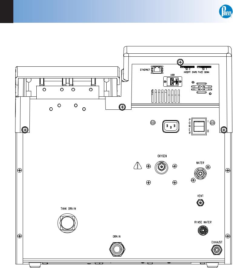
•Make the tap water connection at the rear of the calorimeter using 1/4” Nylon tubing
(HJ0025TB035). The inlet pressure should not exceed 60 psig. Refer to figure 2-1 and 2-2. The inlet connection incorporates a water filter, 1245DD, just behind the inlet connection. When making
the water connection, a back-up wrench should be placed on the water filter to insure a secure
connection and to prevent over tightening the filter.
NOTE:
During extended periods of inactivity (overnight or longer), shut off the tap water supply to the calorimeter.
•Make the connection to the rinse water source using 3/8” Tygon tubing (JT0038TB062A). A barbed fitting is provided at the rear of the calorimeter
for this connection. A 10 liter carboy (231C2) is provided as a distilled water rinse reservoir. Place a 149C in-line water filter at the end of the water line that is inserted into the carboy.
w w w . p a r r i n s t . c o m |
13 |

2 INSTALLATION
INSTALLING THE CALORIMETER (CONTINUED)
•Make the connections to the oxygen supply at this time. Refer to figure 2-2 and 2-3. 1/8” O.D. nylon pressure hose (HX0012TB024) is used to connect the oxygen supply. The inlet connection incorporates a flow restrictor just behind the inlet connection. When making the oxygen connection,
a back-up wrench should be placed on the restrictor to insure a secure connection and to prevent over tightening the flow restrictor. The delivery pressure for oxygen should be set at 450 psig. To install the regulator, unscrew the protecting cap from the tank and inspect the threads on the tank outlet to be sure they are clean and in good condition. Place the ball end of the regulator in the tank outlet and draw up the union nut tightly, keeping the gages tilted slightly back from an upright position. Open the tank valve and check for leaks. The bomb must never be filled to more than 600 psig (40 atm).
Note:
The cause of any leaks must be corrected before proceeding.
Note:
During extended periods of inactivity (overnight or longer), close the tank valve to prevent depleting the tank in the event of a leak. When changing tanks, close the tank valve prior to re-moving the regulator. Do not use oil or combustible lubricants in connection with any part of the oxygen filling system. Keep all threads, fittings and gaskets clean and in good condition.
•The exhaust and vent connections at the rear of the calorimeter, are made with the dual tube A1006DD assembly. The end of the assembly with the bomb exhaust diffuser should be placed into the 10 liter carboy (231C2). The carboy should be placed at
or below the level of the calorimeter to facilitate complete draining of these lines.
Note:
This step is optional for use with A1050DD. See Appendix
G for A1050DD Bomb Rinse Container Installation and
Use.
•Connect the printer USB cable between the 1758
printer and the connections at the rear of the calorimeter. Install the printer ribbon and printer paper at this time. Apply power to the calorimeter and turn on the printer.
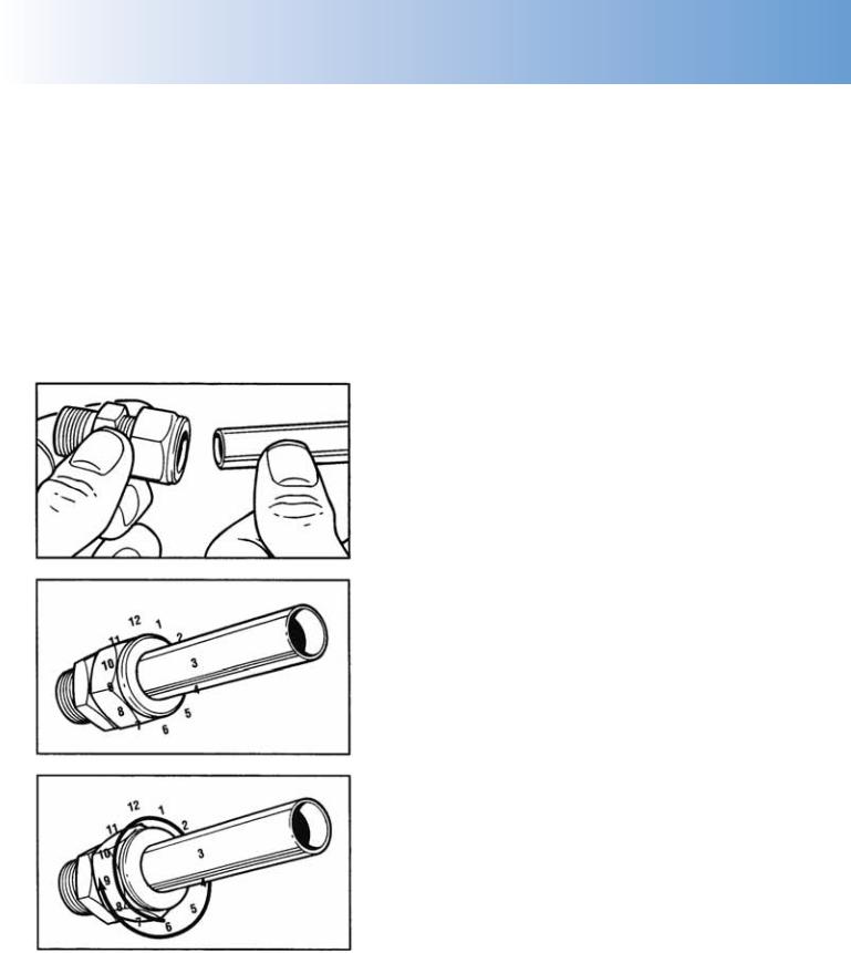
SWAGELOK TUBE FITTINGS
When Swagelok Tube Fittings are used, the instructions for installation are:
1. Simply insert the tubing into the Swagelok Tube
14 |
P a r r I n s t r u m e n t C o m p a n y |
6300 |
INSTALLATION |
2 |
|
|
|
Fitting. Make sure that the tubing rests firmly on the shoulder of the fitting and that the nut is fingertight.
2.Before tightening the Swagelok nut, scribe the nut at the 6 o’clock position.
3.While holding the fitting body steady with a backup wrench, tighten the nut 1-1/4 turns. Watch the scribe mark, make one complete revolution and continue to the 9 o’clock position.
4.For 3/16” and 4mm or smaller tube fittings, tighten the Swagelok nut 3/4 turns from finger-tight.
Figure 2-1
Swagelok Tube Fittings
RETIGHTENING SWAGELOK TUBE FITTINGS
Swagelok tubing connections can be disconnected and retightened many times. The same reliable leak-
proof seal can be obtained every time the connection is remade using the simple two-step procedure.
1.Insert the tubing with pre-swaged ferrules into the fitting body until the front ferrule seats.
2.Tighten the nut by hand. Rotate the nut to the original position with a wrench. An increase in resistance will be encountered at the original position. Then tighten slightly with a wrench.
Smaller tube sizes (up to 3/16” or 4mm) take less tightening to reach the original position than larger tube sizes.
The type of tubing and the wall thickness also has an effect on the amount of tightening required. Plastic tubing requires a minimal amount of additional tightening while heavy wall metal tubing may require somewhat more tightening. In general, the nut only needs to be tightened about 1/8 turn beyond finger tight where the ferrule seats in order to obtain a tight seal.
Over tightening the nut should be avoided. Over tightening the nut causes distortion (flaring) of the lip of the tube fitting where the ferrule seats. This in turn causes the threaded portion of the body to deform. It becomes difficult to tighten the nut by hand during a subsequent re-tightening when the fitting body becomes distorted in this manner.
w w w . p a r r i n s t . c o m |
15 |
2 INSTALLATION
Figure 2-2
6300 Calorimeter Back Panel
16 |
P a r r I n s t r u m e n t C o m p a n y |
6300 |
INSTALLATION |
2 |
|
|
|
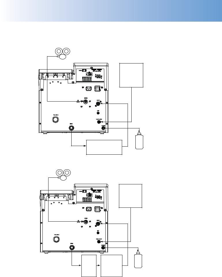
6300 CALORIMETER EXTERNAL PLUMBING |
||
Figure 2-3 |
|
|
Closed Loop Configuration with 6520A |
|
|
O2 Regulator |
|
|
|
DI Water |
|
|
~Room Temp |
|
|
5-10 °C |
|
|
6520A |
Rinse Collection |
|
|
|
Water Recircualtion |
|
|
|
System |
|
Figure 2-4 |
|
|
Closed Loop Configuration with 1564 |
|
|
O2 Regulator |
|
|
|
DI Water |
|
|
~Room Temp |
|
|
5-10 °C |
|
1552 |
1564 |
Rinse Collection |
|
||
Water |
|
|
Water |
|
|
Recircualtion |
|
|
Cooler |
|
|
System |
|
|
|
|
|
Line 1 & 2 – Maximum length of 10 feet, 1/4” OD, Polyurethane (Part Number HJ0025TB035) Line 3 - Maximum length of 25 feet, 1/8” OD, Nylon (Part Number HX0012TB024)
w w w . p a r r i n s t . c o m |
17 |
2 INSTALLATION
6300 CALORIMETER EXTERNAL PLUMBING (CONTINUED)
Figure 2-5 |
|
Open Loop Configuration with 1552 |
|
O2 Regulator |
|
Tap Water |
|
· <25 °C |
DI Water |
· <85 ppm |
~Room Temp |
· <60 psig |
|
1552 |
|
Water |
|
Cooler |
|
|
Rinse Collection |
Drain |
|
Figure 2-6 |
|
Open Loop Configuration |
|
O2 Regulator |
|
Tap Water |
|
· <25 °C |
DI Water |
· <85 ppm |
~Room Temp |
· <60 psig |
|
5-10 °C |
|
|
Rinse Collection |
Drain |
|
Line 1 & 2 – Maximum length of 10 feet, 1/4” OD, Polyurethane (Part Number HJ0025TB035) Line 3 - Maximum length of 25 feet, 1/8” OD, Nylon (Part Number HX0012TB024)
18 |
P a r r I n s t r u m e n t C o m p a n y |

6300 |
INSTALLATION |
2 |
|
INSTALLING THE CALORIMETER (CONTINUED) |
|
|
|
ENTER to store the default sample mass of 1 gram. |
|||
This test should go through Fill, Pre-period, Post- |
|||
|
|||
• After the calorimeter displays the main menu, press |
period and Cool/Rinse Cycles without error. The |
||
calorimeter is now ready to be standardized. |
|||
the Calorimeter Operation button. This screen |
• The calorimeter must be accurately standardized |
||
should indicate that the jacket is filling with water. |
|||
The initial fill can take as long as 8 to 10 minutes |
prior to actually performing calorimetric tests on |
||
to complete. If the jacket filling process times out, |
sample materials. Review Appendix C – Standard- |
||
simply acknowledge the timeout message to resume |
ization, in order to become familiar with the general |
||
the jacket filling process. After the jacket is filled |
procedure and calculations. The user should config- |
||
press the Heater and Pump button in order to toggle |
ure the calorimeter at this time to accommodate the |
||
the heater and pump on. |
desired sample weight entry mode. The calorimeter |
||
• Wait for the calorimeter jacket temperature to |
can be placed into the standardization mode on |
||
the Calorimeter Operation Page, by pressing the |
|||
stabilize within a half a degree of 30 °C. (When |
Operating Mode button. If two bomb heads are |
||
the pump and heater are turned on after being off |
being used with the calorimeter to maximize sample |
||
for an extended period of time, it may take longer |
throughput, the calorimeter can be configured to |
||
than 10 minutes for the calorimeter warm up. This |
prompt for a Bomb ID at the start of each test. The |
||
may cause an error. Simply restart the heater and |
Bomb ID can also be selected on the Calorimeter |
||
pump.) While waiting for the jacket temperature to |
Operations Page by pressing the Bomb Installed/ |
||
stabilize, raise the calorimeter lid and remove the |
EE key. Both bomb heads will need to be standard- |
||
bomb head by twisting 1/16 turn counterclockwise |
ized separately. The end result of a standardization |
||
and pulling straight up. Examine the bomb release |
test is an energy equivalent value, or the amount of |
||
pin at the bottom of the combustion cylinder. If it |
energy required to raise the calorimeter one degree. |
||
has become dislodged during shipping, position it |
Repeated standardization with any given bomb |
||
correctly using the long forceps supplied in the calo- |
head should yield an energy equivalent value with |
||
rimeter accessory kit. Refer to figure F-19. |
a range of up to 4 calories per degree, centered on |
||
• Lock the head in the bomb cylinder (see section |
the mean value for all tests using that bomb head. |
||
The calorimeter is ready for testing samples after a |
|||
5-7), close the lid and while applying a slight |
suitably constant energy equivalent value has been |
||
downward pressure. Press the CALORIMETER |
obtained. |
||
OPERATION key on the main menu followed by |
|
|
|
the Pretesting Cycle button to initiate a pre-test |
|
|
|
cycle. (This button will not be available until the |
|
|
|
jacket temperature has been stable for 15 minutes.) |
|
|
|
During the initial portion of this cycle, check to |
|
|
|
see that the oxygen supply pressure is set to 450 |
|
|
|
psig. Adjust as required. The calorimeter should |
|
|
|
complete the pre-test cycle with no errors. |
|
|
|
• Assemble the bomb head stand (A38A), located in |
|
|
|
the accessory kit. Remove the head from the calo- |
|
|
|
rimeter and place it on the stand. Place a 1 gram |
|
|
|
pellet of benzoic acid in a combustion capsule |
|
|
|
and place this unweighed sample on the capsule |
|
|
|
holder of the bomb head. Attach 10 cm of fuse |
|
|
|
thread as shown in figure 5-3. Install the bomb |
|
|
|
head in the calorimeter and close the cover. Apply |
|
|
|
a slight downward pressure on the cover and press |
|
|
|
the START key to begin the test sequence. Press |
|
|
|
the ENTER key to accept the displayed sample ID |
|
|
|
number. At the sample weight prompt press 1 then |
|
|
|
w w w . p a r r i n s t . c o m |
19 |

2 INSTALLATION
This page intentionally left blank.
20 |
P a r r I n s t r u m e n t C o m p a n y |
6300
CHAPTER 3
INSTRUMENT DESCRIPTION
TYPES OF CONTROLS
All calorimeter configurations and operations are handled by a menu-driven system operated from the bright touch screen display. The settings and controls are organized into nine main sections or pages which comprise the MAIN MENU.
Note:
Keys with a double box in the upper left hand corner lead to sub-menus.
INSTRUMENT DESCRIPTION 3
Some keys lead to multiple choices. Always clear the current value before entering a new value. Once entered the screen will revert to the previous menu and the new value will be displayed in the lower right corner of the key.
4.Data Displays. Most of these keys display values that have been calculated by the calorimeter and are informational only. Certain ones can be overridden by the user entering a desired value through a submenu. The value is displayed in the lower right corner of the key.
Note:
Some keys will respond with an opportunity for the user to confirm the specified action to minimize accidental disruptions to the program and/or stored data.
MENU KEYS
The controls that change the data field information in the menus will be one of the following:
1.Toggles. These data fields contain ON/OFF or YES/NO choices. Simply touching the key on the screen toggles the choice to the other option. The current setting is displayed in the lower right corner of the key.
2.Option Selection. These data fields contain a list of options. Touching the key on the screen steps the user through the available choices. The current setting is displayed in the lower right corner of the key.
3.Value Entry Fields. These data fields are used to enter data into the calorimeter. Touching the key on the screen brings up a sub menu with a key pad or similar screen for entering the required value.
CONTROL KEYS
There are five control keys which always appear in the right column of the primary displays. These keys are unavailable when they are gray instead of white.
1.Escape. This key is used to go up one level in the menu structure.
2.Main Menu. This key is used to return to the main menu touch screen from anywhere in the menu structure.
3.Start. This key is used to start a calorimeter test.
4.Report. This key is used to access the test results stored in the calorimeter, to enter thermochemical corrections and to initiate report on the display, printer or attached computer
5.Help. This key is used to access help screens related to the menu currently displayed on the touch screen.
6.Abort. This key appears in the Start key location while a test or pretest is running. Pressing this key will abort the test or pretest in progress.
7. This key appears in the Escape key location when the main menu is displayed. This key is used to shut down the calorimeter program before turning off the power.
w w w . p a r r i n s t . c o m |
21 |

3 INSTRUMENT DESCRIPTION
This page left blank intentionally.
22 |
P a r r I n s t r u m e n t C o m p a n y |

6300 |
PROGRAM INSTALLATION & CONTROL |
4 |
|
|
|
CHAPTER 4
PROGRAM INSTALLATION &
CONTROL
SOFTWARE INSTALLATION
The program in the 6300 Calorimeter can be extensively modified to tailor the unit to a wide variety of operating conditions, reporting units, laboratory techniques, available accessories and communication modes.
In addition, the calculations, thermochemical corrections and reporting modes can be modified to conform to a number of standard test methods and procedures.
Numerous provisions are included to permit the use of other reagent concentrations, techniques, combustion aids and short cuts appropriate for the user’s work.
Note:
Changes to the program are made by use of the menu structure described in Appendix A of this manual. Any of these items can be individually entered at any time to revise the operating program.
REVISING DEFAULT SETTINGS
The default parameters of the 6300 Calorimeter can be changed to guarantee that the 6300 Calorimeter, when cold restarted, will always be in the desired configuration before beginning a series of tests.
Users who wish to permanently revise their default settings may do so using the following procedure:
•Establish the operating parameters to be stored as the user default settings.
•Go to the Program Info and Control Menu, User/ Factory Settings, User Setup ID, and enter the desired User Setup ID.
•Select Save User Default Settings
To re-load the user default settings, go to the Program Info and Control Page, User/Factory Settings, Re-load User Default Settings, and YES.
DEFAULT SETTINGS
Units are pre programmed with DEFAULT SETTINGS. See pages 24 and 25 for a listing of the factory default settings.
These default settings remain in effect until changed by the user. Should the user ever wish to return to the factory default settings, go to the Program Information and Control Menu, then to User/Factory Settings, and then touch Reload Factory Default Settings and YES.
Non-volatile memory is provided to retain any and all operator initiated program changes; even if power is interrupted or the unit is turned off. If the unit experiences an intentional or unintentional “Cold
Restart”, the controller will return to its default settings.
w w w . p a r r i n s t . c o m |
23 |

4 PROGRAM INSTALLATION & CONTROL
Figure 4-1
6300 Factory Default Settings
Calorimeter Operations
Operating Mode |
Determination |
Bomb Installed/EE |
1/940.0 |
|
|
Heater and Pump |
OFF |
|
|
|
|
Operating Controls |
|
|
|
Method of Operation |
Dynamic |
|
|
Reporting Units |
BTU/lb |
|
|
Use Spiking Correction |
OFF |
|
|
“OTHER” Multiplier |
4.1868 |
|
|
Calibrate Touchscreen |
|
|
|
LCD Backlight Timeout(s) |
1200 S |
|
|
LCD Backlight Intensity |
70% |
|
|
Print Error Messages |
ON |
|
|
Language |
English |
|
|
|
|
Spike Controls |
|
|
|
Use Spiking |
OFF |
|
|
Heat of Combustion of Spike |
6318.4 |
|
|
Use Fixed Spike |
OFF |
|
|
Weight of Fixed Spike |
0.0 |
|
|
Prompt for Spike before Weight |
OFF |
|
|
|
|
Bomb Rinse Tank Control |
|
|
|
Report Rinse Tank Empty |
ON |
|
|
Rinse Tank Capacity |
150 |
|
|
# Rinses Left |
150 |
|
|
Reset Rinse Tank Counter |
|
|
|
Rinse Time |
25 |
|
|
Rinse Flush Time |
20 |
|
|
Clear Time |
100 |
|
|
# of Rinse Cycles |
3 |
|
|
|
|
Program Information and Control |
|
|
|
Date & Time Settings |
|
|
|
Volume Level Adjust |
85% |
|
|
Software and Hardware Info |
|
|
|
Settings Protect |
OFF |
|
|
User/Factory Settings |
|
|
|
Feature Key |
|
|
|
Bomb Type Select |
|
User Function Setup
Cold Restart
User/Factory Settings
User Setup ID |
63-1138 |
Reload Factory Default Settings
Reload User Default Settings
Save User Default Settings
Compare settings with Factory Defaults
Calibration Data & Controls
Calibration Run Limit |
10 |
EE Max Std Deviation |
0.0 |
|
|
Heat of Combustion of Standard |
6318.4 |
|
|
Bomb Service Interval |
500 |
|
|
Use Bomb |
1 |
|
|
|
|
Control Chart Parameters |
|
|
|
Charted Value |
HOC Standard |
|
|
Process Sigma |
0.1 |
|
|
Temp Rise High Warning |
8.5 |
|
|
Temp Rise Low Warning |
5.1 |
|
|
|
|
|
|
Bomb 1 Through 4 |
|
|
|
EE Value |
800.0 |
|
|
Protected EE Value |
OFF |
|
|
|
|
Thermochemical Corrections Standardization |
|
|
|
Fixed Fuse |
ON 50.0 |
|
|
Acid Correction |
Fixed HNO3 8.0 |
Fixed Sulfur |
ON 0.0 |
|
|
|
|
Determination |
|
|
|
Fixed Fuse |
ON 50.0 |
|
|
Acid Correction |
Fixed HNO3 8.0 |
Fixed Sulfur |
OFF 0.0 |
|
|
Net Heat/Dry Factors |
|
|
|
|
|
Calculation Factors |
|
|
|
Nitric Acid Factor |
1.58 |
24 |
P a r r I n s t r u m e n t C o m p a n y |

6300 |
PROGRAM INSTALLATION & CONTROL |
4 |
|
|
|
Factory Default Settings
Continued
Acid Multiplier |
0.0709 |
|
|
Sulfur Value is Percent |
ON |
|
|
Sulfur Multiplier |
0.6238 |
|
|
Fuse Multiplier |
1.0 |
|
|
Use Offset Correction (ISO) |
OFF |
|
|
Offset Value |
0.0 |
|
|
|
|
Net Heat/Dry Factors |
|
|
|
Fixed Hydrogen |
OFF 0.0 |
|
|
Fixed Oxygen |
ON 0.0 |
|
|
Fixed Nitrogen |
ON 0.0 |
|
|
Calculate Net Heat of Combustion |
OFF |
|
|
Fixed Moisture as Determined |
OFF 0.0 |
|
|
Fixed Moisture as Received |
OFF 0.0 |
|
|
Dry Calculation |
OFF |
|
|
|
|
Data Entry Controls |
|
|
|
Prompt for Bomb ID |
ON |
|
|
Weight Entry Mode |
Touch Screen |
|
|
Acid Entry Mode |
Touch Screen |
|
|
Net Heat Entry Modes |
Touch Screen |
|
|
Auto Sample ID Controls |
ON |
|
|
Sample Weight Warning above |
2.0 |
|
|
Spike Weight Entry Mode |
Touch Screen |
|
|
Sulfur Entry Mode |
Touch Screen |
|
|
Moisture Entry Modes |
Touch Screen |
|
|
Auto Preweigh Controls |
ON |
|
|
|
|
Auto Sample ID Controls |
|
|
|
Automatic Sample ID |
ON |
|
|
Automatic Sample ID Increment |
1 |
|
|
Automatic Sample ID Number |
1 |
|
|
|
|
Auto Preweigh Controls |
|
|
|
Automatic Preweigh ID |
ON |
|
|
Automatic Preweigh ID Increment |
1 |
|
|
Automatic Preweigh ID Number |
1 |
|
|
|
|
Reporting Controls |
|
|
|
Report Width |
40 |
|
|
Automatic Reporting |
|
ON |
|
|
|
Auto Report Destination |
|
Printer |
|
|
|
Individual Printed Reports |
|
OFF |
|
|
|
Edit Final Reports |
|
OFF |
|
|
|
Recalculate Final Reports |
|
OFF |
|
|
|
Use New EE Values in Recalculation |
OFF |
|
|
|
|
Report Schedule |
End of Postperiod |
|
|
|
|
|
|
|
Communication Controls |
|
|
|
|
|
Printer Type |
|
Parr 1758 |
|
|
|
Balance Port |
|
|
|
|
|
Network Interface |
|
|
|
|
|
Printer Destination |
|
Local USB |
|
|
|
Bar Code Port |
|
|
|
|
|
Network Data Devices |
|
|
|
|
|
|
|
|
Balance Port Communications |
|
|
|
|
|
Balance Type |
|
Generic |
|
|
|
Balance Port Device |
|
|
|
|
|
Customize Balance Settings |
|
|
|
|
|
|
|
|
Balance Port Settings |
|
|
|
|
|
Number of Data Bits |
|
8 |
|
|
|
Parity |
|
None |
|
|
|
Number of Stop Bits |
|
1 |
|
|
|
Handshaking |
|
None |
|
|
|
Baud Rate |
|
9600 |
|
|
|
Data Characters from Balance |
|
8 |
|
|
|
Data Precision |
|
4 |
|
|
|
Transfer Timeout (seconds) |
|
10 |
|
|
|
Balance Handler Strings |
|
|
|
|
|
|
|
|
Data Logger |
|
|
|
|
|
Data Logger |
|
OFF |
|
|
|
Data Log Interval |
|
12s |
|
|
|
Data Log Destination |
|
Log File and |
|
|
Printer |
|
|
|
Select Data Log Items |
|
|
|
|
|
Data Log Format |
|
Text Format |
|
|
|
w w w . p a r r i n s t . c o m |
25 |

4 PROGRAM INSTALLATION & CONTROL
This page intentionally left blank.
26 |
P a r r I n s t r u m e n t C o m p a n y |

6300 |
OPERATING INSTRUCTIONS |
5 |
|
|
|
CHAPTER 5
OPERATING INSTRUCTIONS
TO BEGIN A TEST
1.Weigh the sample to 0.1 mg.
2.Gently tap the capsules that contain powdered samples to compact the material. (Pellets are easier to handle than loose samples and they burn slower in the bomb, thereby reducing the chances for incomplete combustion.)
3.Carefully place the capsule into the capsule holder.
4.Attach 10 cm of ignition thread (see Figure 5-2).
5.Install bomb head in calorimeter.
6.Close calorimeter cover making certain the latch is engaged
7.Select determination or standardization as appropriate on Calorimeter Operations Page, Operating Mode.
8.Press START to begin the test. Calorimeter will prompt operator for Cal ID number, Sample ID numbers and weights in accordance with operating modes set into the instrument.
OPERATING THE OXYGEN BOMB
Combustion with oxygen in a sealed bomb is a very effective and reliable method for releasing all heat energy obtainable from a sample, and for preparing hydrocarbon compounds and carbonaceous materials for analysis.
Note:
The following precautions must always be observed when using this equipment:
1.Do not overcharge the bomb with sample or with a sample which might react with explosive violence.
2.Do not overcharge the bomb with oxygen. The initial charging pressure should not exceed 40 atm (600 psig).
3.Do not fire the bomb if there is any indication that it is leaking.
4.Stand away from the calorimeter during firing and for at least 20 seconds after firing.
5.Keep the bomb in good condition at all times. Any parts that show signs of weakness or deterioration must be replaced promptly.
6.Read the maintenance and safety instructions before starting to use the bomb, and urge all operating personnel to read these instructions often.
Note:
Tape should always be stored in a sealed container to minimize changes in its moisture and solvent content.
w w w . p a r r i n s t . c o m |
27 |

5 OPERATING INSTRUCTIONS
|
Figure 5-1 |
|
Fill Flow Diagram |
28 |
P a r r I n s t r u m e n t C o m p a n y |
6300
ALLOWABLE SAMPLE SIZE
To stay within safe limits, the bomb should never be charged with a sample which will release more than 8000 calories when burned in oxygen.
The initial oxygen pressure is set at 30 atmospheres (450 psig). This generally limits the mass of the combustible charge (sample plus benzoic acid, gelatin, firing oil or any combustion aid) to not more than 1.1 grams.
When starting tests with new or unfamiliar materials, it is always best to use samples of less than .7 gram with the possibility of increasing the amount if preliminary tests indicate no abnormal behavior and sample will not exceed the 8000 calorie limit.
To avoid damage to the bomb and calorimeter, and possible injury to the operator, it should be a standing rule in each laboratory that the bomb must never be charged with more than 1.5 grams of combustible material.
Samples containing sulfur should contain no more than 50 mg of sulfur and have a calorific value of at least 9000 BTU/lb.
Samples containing chlorine should be spiked to insure that sample contains no more than 100 mg of chlorine and liberates at least 5000 calories.
ATTACHING THE COTTON THREAD
Remove any moisture from the heating wire prior to attaching the cotton thread.
A cotton thread (845DD) is used as an auxiliary fuse to ignite the sample (See Figure 5-2).
Four inches of thread is recommended for this auxiliary thread which is looped over the heating wire, doubled on itself, twisted to form a single strand and fed into the sample cup to lay on the sample.
When contact is made through the heating wire, the thread will ignite, drop into the sample cup and ignite the sample.
One spool of thread, part number 845DD, is 563 yards. Part number 845DD2 contains approximately 1000 pieces of thread pre-cut to 4 inches.
OPERATING INSTRUCTIONS 5
Figure 5-2
Cotton Thread Assembly
w w w . p a r r i n s t . c o m |
29 |

5 OPERATING INSTRUCTIONS
WARNING - DO NOT OVERFILL THE BOMB
The safety relief valve on the regulator should protect the system from an over fill. If for any reason, the bomb should accidentally be charged to more than 600 psig (40 atm), do not fire the bomb. The dangerous pressures which might develop under such conditions could damage the bomb and injure the operator. If there is any reason to believe that the bomb has been over-filled, stop the filling operation immediately, exhaust the bomb and open it to check for any loss of sample before repeating the filling procedure.
Figure 5-3
Pre-period/Post-period
30 |
|
|
|
|
|
|
|
|
|
|
|
|
|
|
|
|
|
|
|
|
|
|
|
|
|
|
|
|
|
|
|
|
|
|
|
|
|
|
|
|
|
|
|
|
|
|
|
|
|
|
|
|
|
|
|
|
|
|
|
|
|
|
|
|
|
|
|
|
|
|
|
|
|
|
|
|
|
|
|
|
|
|
|
|
|
|
|
|
|
|
|
|
|
|
|
|
|
|
|
|
|
|
|
|
|
|
|
|
|
|
|
|
|
|
|
|
|
|
|
|
|
|
|
|
|
|
|
|
|
|
|
|
|
|
|
|
|
|
|
|
|
|
|
|
|
|
|
|
|
|
|
|
|
|
|
|
|
|
|
|
|
|
|
|
|
|
|
|
|
|
|
|
|
|
|
|
|
|
|
|
|
|
|
|
|
|
|
|
|
|
|
|
|
|
|
|
|
|
|
|
|
|
|
|
|
|
|
|
|
|
|
|
|
|
|
|
|
|
|
|
|
|
|
|
|
|
|
|
|
|
|
|
|
|
|
|
|
|
|
|
|
|
|
|
|
|
|
|
|
|
|
|
|
|
|
|
|
|
|
|
|
|
|
|
|
|
|
|
|
|
|
|
|
|
|
|
|
|
|
|
|
|
|
|
|
|
|
|
|
|
|
|
|
|
|
|
|
|
|
|
|
|
|
|
|
|
|
|
|
|
|
|
|
|
|
|
|
|
|
|
|
|
|
|
|
|
|
|
|
|
|
|
|
|
|
|
|
|
|
|
|
|
|
|
|
|
|
|
|
|
|
|
|
|
|
|
|
|
|
|
|
|
|
|
|
|
|
|
|
|
|
|
|
|
|
|
|
|
|
|
|
|
|
|
|
|
|
|
|
|
|
|
|
|
|
|
|
|
|
|
|
|
|
|
|
|
|
|
|
|
|
|
|
|
|
|
|
|
|
|
|
|
|
|
|
|
|
|
|
|
|
|
|
|
|
|
|
|
|
|
|
|
|
|
|
|
|
|
|
|
|
|
|
|
|
|
|
|
|
|
|
|
|
|
|
|
|
|
|
|
|
|
|
|
|
|
|
|
|
|
|
|
|
|
|
|
|
|
|
|
|
|
|
|
|
|
|
|
|
|
|
|
|
|
|
|
|
|
|
|
|
|
|
|
|
|
|
|
|
|
|
|
|
|
|
|
|
|
|
|
|
|
|
|
|
|
|
|
|
|
|
|
|
|
|
|
|
|
|
|
|
|
|
|
|
|
|
|
|
|
|
|
|
|
|
|
|
|
|
|
|
|
|
|
|
|
|
|
|
|
|
|
|
|
|
|
|
|
|
|
|
|
|
|
|
|
|
|
|
|
|
|
|
|
|
|
|
|
|
|
|
|
|
|
|
|
|
|
|
|
|
|
|
|
|
|
|
|
|
|
|
|
|
|
|
|
|
|
|
|
|
|
|
|
|
|
|
|
|
|
|
|
|
|
|
|
|
|
|
|
|
|
|
|
|
|
|
|
|
|
|
|
|
|
|
|
|
|
|
|
|
|
|
|
|
|
|
|
|
|
|
|
|
|
|
|
|
|
|
|
|
|
|
|
|
|
|
|
|
|
|
|
|
|
|
|
|
|
|
|
|
|
|
|
|
|
|
|
|
|
|
|
|
|
|
|
|
|
|
|
|
|
|
|
|
|
|
|
|
|
|
|
|
|
|
|
|
|
|
|
|
|
|
|
|
|
|
|
|
|
|
|
|
|
|
|
|
|
|
|
|
|
|
|
|
|
|
|
|
|
|
|
|
|
|
|
|
|
|
|
|
|
|
|
|
|
|
|
|
|
|
|
|
|
|
|
|
|
|
|
|
|
|
|
|
|
|
|
|
|
|
|
|
|
|
|
|
|
|
|
|
|
|
|
|
|
|
|
|
|
|
|
|
|
|
|
|
|
|
|
|
|
|
|
|
|
|
|
|
|
|
|
|
|
|
|
|
|
|
|
|
|
|
|
|
|
|
|
|
|
|
|
|
|
|
|
|
|
|
|
|
|
|
|
|
|
|
|
|
|
|
|
|
|
|
|
|
|
|
|
|
|
|
|
|
|
|
|
|
|
|
|
|
|
|
|
|
|
|
|
|
|
|
|
|
|
|
|
|
|
|
|
|
|
|
|
|
|
|
|
|
|
|
|
|
|
|
|
|
|
|
|
|
|
|
|
|
|
|
|
|
|
|
|
|
|
|
|
|
|
|
|
|
|
|
|
|
|
|
|
|
|
|
|
|
|
|
|
|
|
|
|
|
|
|
|
|
|
|
|
|
|
|
|
|
|
|
|
|
|
|
|
|
|
|
|
|
|
|
|
|
|
|
|
|
|
|
|
|
|
|
|
|
|
|
|
|
|
|
|
|
|
|
|
|
|
|
|
|
|
|
|
|
|
|
|
|
|
|
|
|
|
|
|
|
|
|
|
|
|
|
|
|
|
|
|
|
|
|
|
|
|
|
|
|
|
|
|
|
|
|
|
|
|
|
|
|
|
|
|
|
|
|
|
|
|
|
|
|
|
|
|
|
|
|
|
|
|
|
|
|
|
|
|
|
|
|
|
|
|
|
|
|
|
|
|
|
|
|
|
|
|
|
|
|
|
|
|
|
|
|
|
|
|
|
|
|
|
|
|
|
|
|
|
|
|
|
|
|
|
|
|
|
|
|
|
|
|
|
|
|
|
|
|
|
|
|
|
|
|
|
|
|
|
|
|
|
|
|
|
|
|
|
|
|
|
|
|
|
|
|
|
|
|
|
|
|
|
|
|
|
|
|
|
|
|
|
|
|
|
|
|
|
|
|
|
|
|
|
|
|
|
|
|
|
|
|
|
|
|
|
|
|
|
|
|
|
|
|
|
|
|
|
|
|
|
|
|
|
|
|
|
|
|
|
|
|
|
|
|
|
|
|
|
|
|
|
|
|
|
|
|
|
|
|
|
|
|
|
|
|
|
|
|
|
|
|
|
|
|
|
|
|
|
|
|
|
|
|
|
|
|
|
|
|
|
|
|
|
|
|
|
|
|
|
|
|
|
|
|
|
|
|
|
|
|
|
|
|
|
|
|
|
|
|
|
|
|
|
|
|
|
|
|
|
|
|
|
|
|
|
|
|
|
|
|
|
|
|
|
|
|
|
|
|
|
|
|
|
|
|
|
|
|
|
|
|
|
|
|
|
|
|
|
|
|
|
|
|
|
|
|
|
|
|
|
|
|
|
|
|
|
|
|
|
|
|
|
|
|
|
|
|
|
|
|
|
|
|
|
|
|
|
|
|
|
|
|
|
|
|
|
|
|
|
|
|
|
|
|
|
|
|
|
|
|
|
|
|
|
|
|
|
|
|
|
|
|
|
|
|
|
|
|
|
|
|
|
|
|
|
|
|
|
|
|
|
|
|
|
|
|
|
|
|
|
|
|
|
|
|
|
|
|
|
|
|
|
|
|
|
|
|
|
|
|
|
|
|
|
|
|
|
|
|
|
|
|
|
|
|
|
|
|
|
|
|
|
|
|
|
|
|
|
|
|
|
|
|
|
|
|
|
|
|
|
|
|
|
|
|
|
|
|
|
|
|
|
|
|
|
|
|
|
|
|
|
|
|
|
|
|
|
|
|
|
|
|
|
|
|
|
|
|
|
|
|
|
|
|
|
|
|
|
|
|
|
|
|
|
|
|
|
|
|
|
|
|
|
|
|
|
|
|
|
|
|
|
|
|
|
|
|
|
|
|
|
|
|
|
|
|
|
|
|
|
|
|
|
|
|
|
|
|
|
|
|
|
|
|
|
|
|
|
|
|
|
|
|
|
|
|
|
|
|
|
|
|
|
|
|
|
|
|
|
|
|
|
|
|
|
|
|
|
|
|
|
|
|
|
|
|
|
|
|
|
|
|
|
|
|
|
|
|
|
|
|
|
|
|
|
|
|
|
|
|
|
|
|
|
|
|
|
|
|
|
|
|
|
|
|
|
|
|
|
|
|
|
|
|
|
|
|
|
|
|
|
|
|
|
|
|
|
|
|
|
|
|
|
|
|
|
|
|
|
|
|
|
|
|
|
|
|
|
|
|
|
|
|
|
|
|
|
|
|
|
|
|
|
|
|
|
|
|
|
|
|
|
|
|
|
|
|
|
|
|
|
|
|
|
|
|
|
|
|
|
|
|
|
|
|
|
|
|
|
|
|
|
|
|
|
|
|
|
|
|
|
|
|
|
|
|
|
|
|
|
|
|
|
|
|
|
|
|
|
|
|
|
|
|
|
|
|
|
|
|
|
|
|
|
|
|
|
|
|
|
|
|
|
|
|
|
|
|
|
|
|
|
|
|
|
|
|
|
|
|
|
|
|
|
|
|
|
|
|
|
|
|
|
|
|
|
|
|
|
|
|
|
|
|
|
|
|
|
|
|
|
|
|
|
|
|
|
|
|
|
|
|
|
|
|
|
|
|
|
|
|
|
|
|
|
|
|
|
|
|
|
|
|
|
|
|
|
|
|
|
|
|
|
|
|
|
|
|
|
|
|
|
|
|
|
|
|
|
|
|
|
|
|
|
|
|
|
|
|
|
|
|
|
|
|
|
|
|
|
|
|
|
|
|
|
|
|
|
|
|
|
|
|
|
|
|
|
|
|
|
|
|
|
|
|
|
|
|
|
|
|
|
|
|
|
|
|
|
|
|
|
|
|
|
|
|
|
|
|
|
|
|
|
|
|
|
|
|
|
|
|
|
|
|
|
|
|
|
|
|
|
|
|
|
|
|
|
|
|
|
|
|
|
|
|
|
|
|
|
|
|
|
|
|
|
|
|
|
|
|
|
|
|
|
|
|
|
|
|
|
|
|
|
|
|
|
|
|
|
|
|
|
|
|
|
|
|
|
|
|
|
|
|
|
|
|
|
|
|
|
|
|
|
|
|
|
|
|
|
|
|
|
|
|
|
|
|
|
|
|
|
|
|
|
|
|
|
|
|
|
|
|
|
|
|
|
|
|
|
|
|
|
|
|
|
|
|
|
|
|
|
|
|
|
|
|
|
|
|
|
|
|
|
|
|
|
|
|
|
|
|
|
|
|
|
|
|
|
|
|
|
|
|
|
|
|
|
|
|
|
|
|
|
|
|
|
|
|
|
|
|
|
|
|
|
|
|
|
|
|
|
|
|
|
|
|
|
|
|
|
|
|
|
|
|
|
|
|
|
|
|
|
|
|
|
|
|
|
|
|
|
|
|
|
|
|
|
|
|
|
|
|
|
|
|
|
|
|
|
|
|
|
|
|
|
|
|
|
|
|
|
|
|
|
|
|
|
|
|
|
|
|
|
|
|
|
|
|
|
|
|
|
|
|
|
|
|
|
|
|
|
|
|
|
|
|
|
|
|
|
|
|
|
|
|
|
|
|
|
|
|
|
|
|
|
|
|
|
|
|
|
|
|
|
|
|
|
|
|
|
|
|
|
|
|
|
|
|
|
|
|
|
|
|
|
|
|
|
|
|
|
|
|
|
|
|
|
|
|
|
|
|
|
|
|
|
|
|
|
|
|
|
|
|
|
|
|
|
|
|
|
|
|
|
|
|
|
|
|
|
|
|
|
|
|
|
|
|
|
|
|
|
|
|
|
|
|
|
|
|
|
|
|
|
|
|
|
|
|
|
|
|
|
|
|
|
|
|
|
|
|
|
|
|
|
|
|
|
|
|
|
|
|
|
|
|
|
|
|
|
|
|
|
|
|
|
|
|
|
|
|
|
|
|
|
|
|
|
|
|
|
|
|
|
|
|
|
|
|
|
|
|
|
|
|
|
|
|
|
|
|
|
|
|
|
|
|
|
|
|
|
|
|
|
|
|
|
|
|
|
|
|
|
|
|
|
|
|
|
|
|
|
|
|
|
|
|
|
|
|
|
|
|
|
|
|
|
|
|
|
|
|
|
|
|
|
|
|
|
|
|
|
|
|
|
|
|
|
|
|
|
|
|
|
|
|
|
|
|
|
|
|
|
|
|
|
|
|
|
|
|
|
|
|
|
|
|
|
|
|
|
|
|
|
|
|
|
|
|
|
|
|
|
|
|
|
|
|
|
|
|
|
|
|
|
|
|
|
|
|
|
|
|
|
|
|
|
|
|
|
|
|
|
|
|
|
|
|
|
|
|
|
|
|
|
|
|
|
|
|
|
|
|
|
|
|
|
|
|
|
|
|
|
|
|
|
|
|
|
|
|
|
|
|
|
|
|
|
|
|
|
|
|
|
|
|
|
|
|
|
|
|
|
|
|
|
|
|
|
|
|
|
|
|
|
|
|
|
|
|
|
|
|
|
|
|
|
|
|
|
|
|
|
|
|
|
|
|
|
|
|
|
|
|
|
|
|
|
|
|
|
|
|
|
|
|
|
|
|
|
|
|
|
|
|
|
|
|
|
|
|
|
|
|
|
|
|
|
|
|
|
|
|
|
|
|
|
|
|
|
|
|
|
|
|
|
|
|
|
|
|
|
|
|
|
|
|
|
|
|
|
|
|
|
|
|
|
|
|
|
|
|
|
|
|
|
|
|
|
|
|
|
|
|
|
|
|
|
|
|
|
|
|
|
|
|
|
|
|
|
|
|
|
|
|
|
|
|
|
|
|
|
|
|
|
|
|
|
|
|
|
|
|
|
|
|
|
|
|
|
|
|
|
|
|
|
|
|
|
|
|
|
|
|
|
|
|
|
|
|
|
|
|
|
|
|
|
|
|
|
|
|
|
|
|
|
|
|
|
|
|
|
|
|
|
|
|
|
|
|
|
|
|
|
|
|
|
|
|
|
|
|
|
|
|
|
|
|
|
|
|
|
|
|
|
|
|
|
|
|
|
|
|
|
|
|
|
|
|
|
|
|
|
|
|
|
|
|
|
|
|
|
|
|
|
|
|
|
|
|
|
|
|
|
|
|
|
|
|
|
|
|
|
|
|
|
|
|
|
|
|
|
|
|
|
|
|
|
|
|
|
|
|
|
|
|
|
|
|
|
|
|
|
|
|
|
|
|
|
|
|
|
|
|
|
|
|
|
|
|
|
|
|
|
|
|
|
|
|
|
|
|
|
|
|
|
|
|
|
|
|
|
|
|
|
|
|
|
|
|
|
|
|
|
|
|
|
|
|
|
|
|
|
|
|
|
|
|
|
|
|
|
|
|
|
|
|
|
|
|
|
|
|
|
|
|
|
|
|
|
|
|
|
|
|
|
|
|
|
|
|
|
|
|
|
|
|
|
|
|
|
|
|
|
|
|
|
|
|
|
|
|
|
|
|
|
|
|
|
|
|
|
|
|
|
|
|
|
|
|
|
|
|
|
|
|
|
|
|
|
|
|
|
|
|
|
|
|
|
|
|
|
|
|
|
|
|
|
|
|
|
|
|
|
|
|
|
|
|
|
|
|
|
|
|
|
|
|
|
|
|
|
|
|
|
|
|
|
|
|
|
|
|
|
|
|
|
|
|
|
|
|
|
|
|
|
|
|
|
|
|
|
|
|
|
|
|
|
|
|
|
|
|
|
|
|
|
|
|
|
|
|
|
|
|
|
|
|
|
|
|
|
|
|
|
|
|
|
|
|
|
|
|
|
|
|
|
|
|
|
|
|
|
|
|
|
|
|
|
|
|
|
|
|
|
|
|
|
|
|
|
|
|
|
|
|
|
|
|
|
|
|
|
|
|
|
|
|
|
|
|
|
|
|
|
|
|
|
|
|
|
|
|
|
|
|
|
|
|
|
|
|
|
|
|
|
|
|
|
|
|
|
|
|
|
|
|
|
|
|
|
|
|
|
|
|
|
|
|
|
|
|
|
|
|
|
|
|
|
|
|
|
|
|
|
|
|
|
|
|
|
|
|
|
|
|
|
|
|
|
|
|
|
|
|
|
|
|
|
|
|
|
|
|
|
|
|
|
|
|
|
|
|
|
|
|
|
|
|
|
|
|
|
|
|
|
|
|
|
|
|
|
|
|
|
|
|
|
|
|
|
|
|
|
|
|
|
|
|
|
|
|
|
|
|
|
|
|
|
|
|
|
|
|
|
|
|
|
|
|
|
|
|
|
|
|
|
|
|
|
|
|
|
|
|
|
|
|
|
|
|
|
|
|
|
|
|
|
|
|
|
|
|
|
|
|
|
|
|
|
|
|
|
|
|
|
|
|
|
|
|
|
|
|
|
|
|
|
|
|
|
|
|
|
|
|
|
|
|
|
|
|
|
|
|
|
|
|
|
|
|
|
|
|
|
|
|
|
|
|
|
|
|
|
|
|
|
|
|
|
|
|
|
|
|
|
|
|
|
|
|
|
|
|
|
|
|
|
|
|
|
|
|
|
|
|
|
|
|
|
|
|
|
|
|
|
|
|
|
|
|
|
|
|
|
|
|
|
|
|
|
|
|
|
|
|
|
|
|
|
|
|
|
|
|
|
|
|
|
|
|
|
|
|
|
|
|
|
|
|
|
|
|
|
|
|
|
|
|
|
|
|
|
|
|
|
|
|
|
|
|
|
|
|
|
|
|
|
|
|
|
|
|
|
|
|
|
|
|
|
|
|
|
|
|
|
|
|
|
|
|
|
|
|
|
|
|
|
|
|
|
|
|
|
|
|
|
|
|
|
|
|
|
|
|
|
|
|
|
|
|
|
|
|
|
|
|
|
|
|
|
|
|
|
|
|
|
|
|
|
|
|
|
|
|
|
|
|
|
|
|
|
|
|
|
|
|
|
|
|
|
|
|
|
|
|
|
|
|
|
|
|
|
|
|
|
|
|
|
|
|
|
|
|
|
|
|
|
|
|
|
|
|
|
|
|
|
|
|
|
|
|
|
|
|
|
|
|
|
|
|
|
|
|
|
|
|
|
|
|
|
|
|
|
|
|
|
|
|
|
|
|
|
|
|
|
|
|
|
|
|
|
|
|
|
|
|
|
|
|
|
|
|
|
|
|
|
|
|
|
|
|
|
|
|
|
|
|
|
|
|
|
|
|
|
|
|
|
|
|
|
|
|
|
|
|
|
|
|
|
|
|
|
|
|
|
|
|
|
|
|
|
|
|
|
|
|
|
|
|
|
|
|
|
|
|
|
|
|
|
|
|
|
|
|
|
|
|
|
|
|
|
|
|
|
|
|
|
|
|
|
|
|
|
|
|
|
|
|
|
|
|
|
|
|
|
|
|
|
|
|
|
|
|
|
|
|
|
|
|
|
|
|
|
|
|
|
|
|
|
|
|
|
|
|
|
|
|
|
|
|
|
|
|
|
|
|
|
|
|
|
|
|
|
|
|
|
|
|
|
|
|
|
|
|
|
|
|
|
|
|
|
|
|
|
|
|
|
|
|
|
|
|
|
|
|
|
|
|
|
|
|
|
|
|
|
|
|
|
|
|
|
|
|
|
|
|
|
|
|
|
|
|
|
|
|
|
|
|
|
|
|
|
|
|
|
|
|
|
|
|
|
|
|
|
|
|
|
|
|
|
|
|
|
|
|
|
|
|
|
|
|
|
|
|
|
|
|
|
|
|
|
|
|
|
|
|
|
|
|
|
|
|
|
|
|
|
|
|
|
|
|
|
|
|
|
|
|
|
|
|
|
|
|
|
|
|
|
|
|
|
|
|
|
|
|
|
|
|
|
|
|
|
|
|
|
|
|
|
|
|
|
|
|
|
|
|
|
|
|
|
|
|
|
|
|
|
|
|
|
|
|
|
|
|
|
|
|
|
|
|
|
|
|
|
|
|
|
|
|
|
|
|
|
|
|
|
|
|
|
|
|
|
|
|
|
|
|
|
|
|
|
|
|
|
|
|
|
|
|
|
|
|
|
|
|
|
|
|
|
|
|
|
|
|
|
|
|
|
|
|
|
|
|
|
|
|
|
|
|
|
|
|
|
|
|
|
|
|
|
|
|
|
|
|
|
|
P a r r I n s t r u m e n t C o m p a n y |
|
|
|
|
|
|
|
|
|
|
|
|
|
|
|
|
|
|
|
|
|
|
|
|
|
|
|
|
|
|
|
|
|
|
|
|
|
||||||||||||||||||||||||||||||||||||||||||||||||||||||||||||||||||||
 Loading...