

Page 1

ORDER No. PCZ1109123CE
REVISION 2
Service Manual
LCD Television
TX-L32C4E
KM10VE Chassis
Specifications
Power Source: 220-240V AC, 50Hz
Rated Power Consumption: 88W
Stand-by Power Consumption: 0.25W (Without monitor out recording)
9.5W (With monitor out recording)
Aerial Impedance: 75 unbalanced, Coaxial Type
Receiving System:
PAL-I/H, B/G, D/K
SECAM B/G, D/K, L/L’
PAL-525/60 (AV only)
DVB-T (Digital Terrestrial Services (MPEG2 and MPEG4-AVC(H.264))
DVB-C (Digital cable services (MPEG2 and MPEG4-AVC(H.264))
M.NTSC (AV only)
NTSC (AV only)
Receiving Channels:
VHF E2-E12 VHF H1-H2 (ITALY)
VHF A-H (ITALY) VHF R1-R2
VHF R3-R5 VHF R6-R12
UHF E21-E69 CATV (S01-S05)
CATV S1-S10 (M1-M10) CATV S11-S20 (U1-U10)
CATV S21-S41 (Hyperband)
Aerial Input: VHF / UHF
Operating Conditions: Temperature: 0°C 35°C
Humidity: 20% 80% RH (non condensing)
© Panasonic Corporation 2011.
Unauthorized copying
distribution is a violation of law.
and
Page 2

Intermediate Frequency:
2
Video/Audio
Video 38.9MHz, 33.9MHz
Audio
33.4MHz (B/G), 33.16MHz (A2)
33.05MHz (NICAM B/G, D/K, L’)
32.4MHz (D/K), 32.66MHz (CZ STEREO)
40.4MHz (L’), 39.75MHz (L’ NICAM)
Colour 34.47MHz (PAL)
34.5MHz, 34.65MHz (SECAM)
38.3MHz, 38.15MHz (SECAM L’)
Terminals:
AV1 IN Video (21 pin) 1V p-p 75
Audio (21 pin) 500mV rms 10k
RGB (21 pin) 0.7V p-p 75
AV1 OUT Video (21 pin) 1V p-p 75
Audio (21 pin) 500mV rms 1k
AV2 IN Video RCA PIN Type x 1 1V p-p 75
AUDIO IN Audio RCA PIN Type x 2 500mV rms 1k (used for HDMI 1 / 2 - AV2 Audio IN)
COMPONENT VIDEO RCA PIN Type x 3 Y:1V p-p 75 (including synchronization)
Pb, Pr: ±0,35V p-p 75
HDMI1, HDMI2 Type A Connector
HDMI2 :HDMI (Version 1.4 with Audio Return Channel)
CARD SLOT SD CARD slot 1
Common Interface slot (Complies with CI+) 1
DIGITAL AUDIO OUT PCM / Dolby Digital / DTS , Fiber optic
LCD screen: VVX32H121G00
1366 x 768, 16:9
Visible Diagonal 800mm
Audio Output: 10W (2x5W), 10% THD
Headphones: 3.5mm (M3), 8 Impedance
Accessories supplied : Remote Control 2 x R6 (UM3) Batteries
Dimensions:
Height: Width: Depth:
Including TV stand 510mm 763mm 196mm
TV set only 478mm 763mm 85mm
Net weight:
Including TV stand 8.0kg
TV set only 7.5kg
Specifications are subject to change without notice.
Weights and dimensions shown are approximate.
Warning
This service information is designed for experienced repair technicians only and is not designed for use by the general public. It does not
contain warnings or cautions to advise non-technical individuals of potencial dangers in attempting to service a product. Products
powered by electricity should be serviced or repaired only by experienced professional technicians. Any attempt to service or repair the
product or products deal within this service information by anyone else could result in serious injury or death.
Page 3

CONTENTS
3
SAFETY PRECAUTIONS .......................................................................... 4
GENERAL GUIDE LINES..................................................................... 4
TOUCH – CURRENT CHECK.............................................................. 4
PREVENTION OF ELECTROSTATIC DISCHARGE (ESD)
TO ELECTROSTATICALLY SENSITIVE (ES) DEVICES .......................... 5
ABOUT LEAD FREE SOLDER (PBF)........................................................ 6
SUGGESTED PB FREE SOLDER ....................................................... 6
APPLICABLE SIGNALS............................................................................. 7
SERVICE HINTS ....................................................................................... 8
CHASSIS BOARD LAYOUT ...................................................................... 9
LOCATION OF LEAD WIRING…………………………………………….9
TECHNICAL DESCRIPTION.....................................................................10
SETTING INSPECTION........................................................................... 11
SELF-CHECK .......................................................................................... 12
POWER LED BLINKING TIMING CHART ............................................... 13
SERVICE MODE FUNCTION .................................................................. 14
SERVICE ................................................................................................ 15
SERVICE TOOL MODE........................................................................... 16
HOTEL MODE ......................................................................................... 17
DATA COPY BY SD CARD ..................................................................... 18
DATA COPY FROM TV SET TO SD CARD ............................................ 19
DATA COPY FROM TV SET TO TV SET................................................ 20
OPTION DESCRIPTION.......................................................................... 21
ADJUSTMENT METHOD ........................................................................ 22
WIRING DIAGRAM.................................................................................. 23
BLOCK DIAGRAMS................................................................................. 24
PARTS LOCATION.................................................................................. 26
REPLACEMENT PARTS LIST................................................................. 28
SCHEMATIC DIAGRAMS........................................................................ 38
A-BOARD (1 OF 17) SCHEMATIC DIAGRAM ................................... 39
P-BOARD (1 OF 3) SCHEMATIC DIAGRAM..................................... 56
GK-BOARD SCHEMATIC DIAGRAM..................................................59
KA-BOARD SCHEMATIC DIAGRAM..................................................60
CONDUCTOR VIEWS ............................................................................. 61
Page 4
Safety Precautions
4
General Guide Lines
1. When servicing, observe the original lead dress. If a short circuit is found, replace all parts which have been overheated
or damaged by the short circuit.
2. After servicing, see to it that all the protective devices such as insulation barriers, insulation papers shields are properly
installed.
3. After servicing, make the following touch current checks to prevent the customer from being exposed to shock hazards.
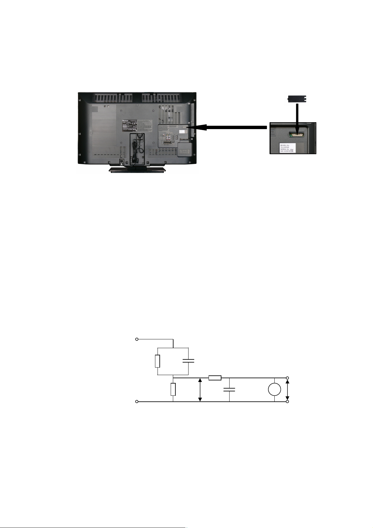
4. Always ensure panel TKP0E16001 is correctly replaced before returning to customer (see Fig.1).
Touch-Current Check
1. Plug the AC cord directly into the AC outlet. Do not use an isolation transformer for this check.
2. Connect a measuring network for touch currents between each exposed metallic part on the set and a good earth
ground such as a water pipe, as shown in Fig. 2.
3. Use Leakage Current Tester (Simpson 228 or equivalent) to measure the potential across the measuring network.
4. Check each exposed metallic part, and measure the voltage at each point.
5. Reserve the AC plug in the AC outlet and repeat each of the above measure.
6. The potential at any point (TOUCH CURRENT) expressed as voltage U1 and U2, does not exceed the following values:
For a. c.: U1 = 35 V (peak) and U2 = 0.35 V (peak);
For d. c.: U1 = 1.0 V,
Note:
The limit value of U2 = 0.35 V (peak) for a. c. and U1 = 1.0 V for d. c. correspond to the values 0.7 mA (peak) a. c. and
2.0 mA d. c.
The limit value U1 = 35 V (peak) for a. c. correspond to the value 70 mA (peak) a. c. for frequencies greater than 100
kHz.
7. In case a measurement is out of the limits specified, there is a possibility of a shock hazard, and the equipment should
be repaired and rechecked before it is returned to the customer.
COLD
WATER PIPE
(EARTH GROUND)
TO
APPLIANCES
EXPOSED
METAL PARTS
Resistance values in ohms ()
V: Voltmetr or oscilloscope
(r.m.s. or peak reading)
NOTE – Appropriate measures should be taken to obtain the correct value in case of non-sinusoidal waveforms
Fig. 1
Measuring network for TOUCH CURRENTS
C
R
=1500
S
R0=500
Input resistance: 1M
Input capacitance:200pF
Frequency range: 15Hz to 1MHz and d.c.respectively
Fig. 2
=0.22F
S
10k
U
1
0.022F
V
U2 (V)
Page 5

Prevention of Electrostatic Discharge (ESD) to Electrostatically
5
Sensitive (ES) Devices
Some semiconductor (solid state) devices can be damaged easily by static electricity. Such components commonly are
called Electrostatically Sensitive (ES) Devices. Examples of typical ES devices are integrated circuits and some field-effect
transistors and semiconductor "chip" components. The following techniques should be used to help reduce the incidence of
component damage caused by electrostatic discharge (ESD).
1. Immediately before handling any semiconductor component or semiconductor-equipped assembly, drain off any ESD on
your body by touching a known earth ground. Alternatively, obtain and wear a commercially available discharging ESD
wrist strap, which should be removed for potential shock reasons prior to applying power to the unit under test.
2. After removing an electrical assembly equipped with ES devices, place the assembly on a conductive surface such as
aluminum foil, to prevent electrostatic charge build up or exposure of the assembly.
3. Use only a grounded-tip soldering iron to solder or unsolder ES devices.
4. Use only an anti-static solder removal device. Some solder removal devices not classified as "anti-static (ESD
protected)" can generate electrical charge sufficient to damage ES devices.
5. Do not use freon-propelled chemicals. These can generate electrical charges sufficient to damage ES devices.
6. Do not remove a replacement ES device from its protective package until immediately before you are ready to install it.
(Most replacement ES devices are packaged with leads electrically shorted together by conductive foam, aluminum foil
or comparable conductive material).
7. Immediately before removing the protective material from the leads of a replacement ES device, touch the protective
material to the chassis or circuit assembly into which the device will be installed.
Caution
Be sure no power is applied to the chassis or circuit, and observe all other safety precautions.
8. Minimize bodily motions when handling unpackaged replacement ES devices. (Otherwise harmless motion such as the
brushing together of your clothes fabric or the lifting of your foot from a carpeted floor can generate static electricity
(ESD) sufficient to damage an ES device).
There are special components used in this equipment which are important for safety.
These parts are marked by in schematic diagrams, exploded views and replacement parts list. It is essential that
these critical parts should be replaced with manufacturer’s specified parts to prevent shock, fire, or other hazards. Do
not modify the original design without permission of manufacturer.
IMPORTANT SAFETY NOTICE
Page 6
About lead free solder (PbF)
6
Note: Lead is listed as (Pb) in the periodic table of elements.
In the information below, Pb will refer to Lead solder, and PbF will refer to Lead Free Solder.
The Lead Free Solder used in our manufacturing process and discussed below is (Sn+Ag+Cu).
That is Tin (Sn), Silver (Ag) and Copper (Cu) although other types are available.
This model uses Pb Free solder in it’s manufacture due to environmental conservation issues. For service and repair work,
we’d suggest the use of Pb free solder as well, although Pb solder may be used.
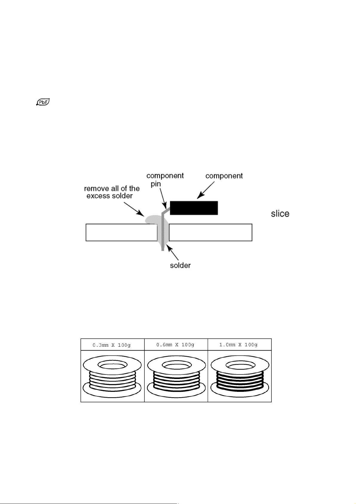
PCBs manufactured using lead free solder will have the PbF within a leaf Symbol
stamped on the back of PCB.
Caution
Pb free solder has a higher melting point than standard solder. Typically the melting point is 50 ~ 70 °F (30~40°C)
higher. Please use a high temperature soldering iron and set it to 700 ± 20 °F (370 ± 10 °C).
Pb free solder will tend to splash when heated too high (about 1100 °F or 600 °C).
If you must use Pb solder, please completely remove all of the Pb free solder on the pins or solder area before
applying Pb solder. If this is not practical, be sure to heat the Pb free solder until it melts, before applying Pb solder.
After applying PbF solder to double layered boards, please check the component side for excess solder which may
flow onto the opposite side. (see Fig.3)
Suggested Pb free solder
There are several kinds of Pb free solder available for purchase. This product uses Sn+Ag+Cu (tin, silver, copper) solder.
However, Sn+Cu (tin, copper), Sn+Zn+Bi (tin, zinc, bismuth) solder can also be used. (see Fig.4)
Fig.3
Fig.4
Page 7

Applicable Signals
7
Component (Y, Pb, Pr), HDMI
Applicable input signal for PC is basically compatible to HDMI standard timing.
Signal name COMPONENT HDMI
525 (480) / 60i * *
525 (480) / 60p * *
625 (576) / 50i * *
625 (576) / 50p * *
750 (720) / 60p * *
750 (720) / 50p * *
1,125 (1,080) / 60i * *
1,125 (1,080) / 50i * *
1,125 (1,080) / 60p *
1,125 (1,080) / 50p *
1,125 (1,080) / 24p *
PC (from HDMI terminal)
Signal name Horizontal frequency (kHz) Vertical frequency (Hz)
640 480 @60 Hz
750 (720) / 60p 45.00 60.00
1,125 (1,080) / 60p 67.50 60.00
Note:
Signals other than above may not be displayed properly.
The above signals are reformatted for optimal viewing on your display.
PC signal is magnified or compressed for display, so that it may not be possible to show fine detail
with sufficient clarity.
31.47 60.00
Page 8
Service Hints
(4pcs)
8
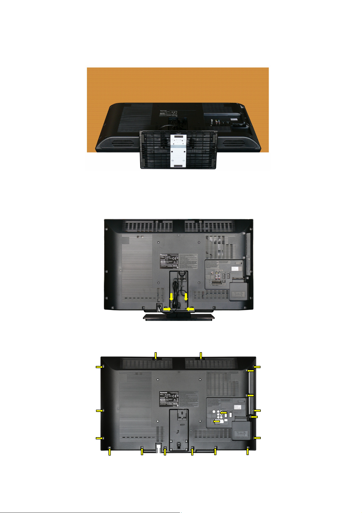
How to remove the backcover
Lay the main unit face down. (see Fig.5)
How to remove the Pedestal assembly
Remove the 4 fixing screws and the pedestal assembly. (see Fig.6)
Remove the 15 fixing screws and the backcover. (see Fig.7)
Fig.5
Fig.6
Fig.7
SCREWS
XYN4+F12FJK
SCREWS
XTV3+12JFJ (19pcs)
Page 9
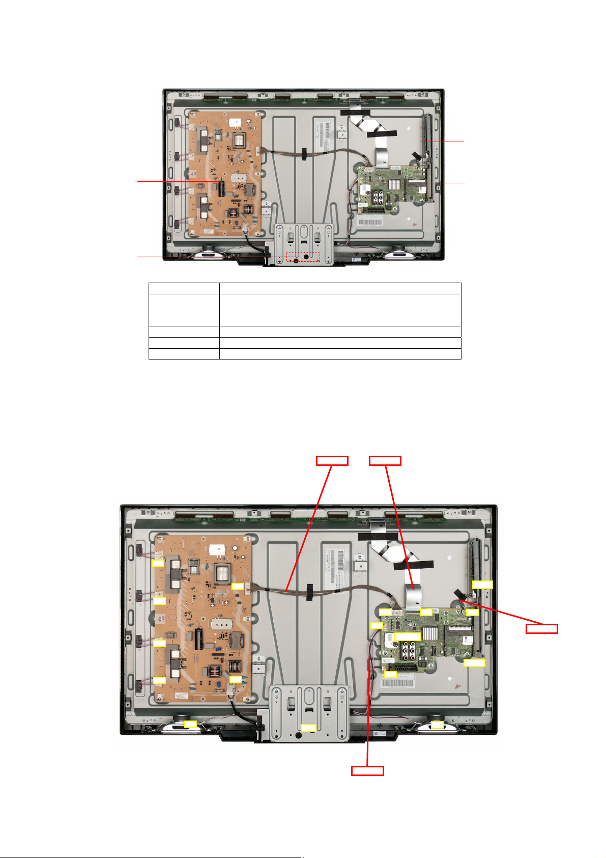
Chassis Board Layout
A
A09A10A
9
P-BOARD
KA-BOARD
Board Name Function
AV Terminal, HDMI, Digital Audio Out,Tv tuner, SD Card
A-Board
P-Board Power Supply, Main Input, Inverter
KA-Board Remote Receiver, R/G LED
GK-Board Control Button, Power Switch
CI slot, sLD2, AV switch, Speaker Out, EEPROM
FlashMemory, DDR SDRAM
Location of Lead Wiring
To find the Part Number of required wire in Replacement Parts List click on the wire name in red box.
A14-PAN A09-P2
GK-BOARD
A-BOARD
P5
P2
P6
14
12
P7
P8
P1
TU4801
GK01
A02
A02-GK01
JK8850
SP
KA10
SP
A-KA-SP
Page 10
Technical Description
10
Specification of KEY for CI Plus, DTCP-IP and One-to-One
General information:
1. EEPROM (IC8902) for spare parts has the seed of KEY for each.
2. The final KEY data will be generated by sLD2 IC (IC8000) when SELF CHECK was done and are stored in both sLD2 IC
(IC8001) and EEPROM (IC8902).
Three KEY are not generated for all models.
The necessary KEY are only generated and stored depend on the feature of models.
Replacement of ICs:
When sLD2 IC (IC8000) is replaced, EEPROM (IC8902) should be also replaced with new one the same time.
When EEPROM (IC8902) is replaced, sLD2 IC (IC8000) is not necessary to be replaced the same time.
After the replacement of IC, SELF CHECK should be done to generate the final KEY data.
How to SELF CHECK: While pressing [VOLUME ( - )] button on the main unit, press [STATUS] button on the remote
control for more than 3 seconds.
TV will be forced to the factory shipment setting after this SELF CHECK.
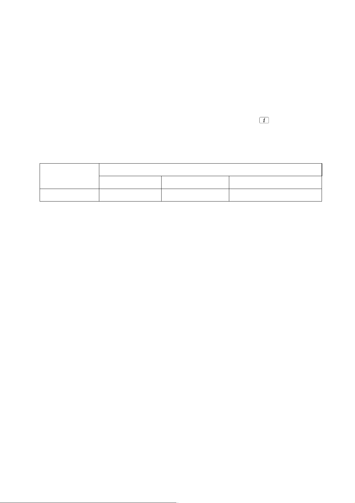
Model and Keys:
Keys
Model No.
CI PLUS DTCP-IP
TX-L32C4E YES NONE NONE
One-to-one
(for USB Rec.)
Page 11

Setting Inspection
11
Voltage Confirmation
A board
Description Test point Voltage
SUB3.3V TP8701 3.21V - 3.45V
SUB1.5 V TP8101 1.47V - 1.56V
SUB1.2V TP8100 1.07V – 1.21V
SUB5V TP0910 4.8V – 5.2V
P board
Description Test point *Voltage **Voltage
DTV16V TP7505/7801 - 15.6V ± 1.5V
STBY6V TP7506 5.8V ± 0.8V 5.8V ± 0.8V
PFC390V TP7201/7202 and
GND TP7203/7204 ***
-
390V ± 15V
* Connect AC 230V to P1 connector
** Connect DC 2.5V to TV_SUB_ON - P2 connector pin 7 /TP7501/ from voltage divider.
*** TP7203/7204 = HOT GROUND (need isolation from COLD GROUND)
Page 12
Self Check
12
Self-check is used to automatically check the bus lines and hexadecimal code of the TV set. To enter Self-Check mode, keep
pressing the down (-/v) button on the TV set and press the STATUS button on the remote control. To exit Self Check,
switch off the TV set at the power button.
TX-L32C4E
32HD
TUN OK
STBY OK
MEM1 OK
MEM2 OK
AVSW OK
TCON-EEP OK
TCON-DCDC OK
TCON-DAC OK
ID OK
Display Ref. No. Description P.C.B.
TUN TU4801 TUNER A-Board
STBY IC8000 sLD2 A-Board
MEM1 IC8901 EEPROM (STM) A-Board
MEM2 IC8902 EEPROM (sLD2) A-Board
AVSW IC3001 AUDIO VIDEO SWITCH A-Board
TCON-EEP IC8000 sLD2 A-Board
TCON-DCDC IC4150 DC/DC CONVERTER A-Board
TCON-DAC IC4120 TCON GAMMA DAC A-Board
ID IC8902 EEPROM (sLD2) A-Board
Panasonic 2011LCD
Self Check Complete
PEAKS-SOFT 1.901
PEAKS-EEP 01.00.0001
LSI-PACKAGE 1.721
LSI-RELEASE 1.00
STBY-SOFT 2.00.00
STBY-EEP 2.01.0000
STBY-ROMCORR 0.00.00
SUM
MODEL ID
c77d
08
034e6100
00000004
If the CCU ports have been checked and found to be incorrect or not located then " - - " will appear in place of "O.K.".
Page 13

Power LED blinking timing chart
13
1. Subject
Information of LED Flashing timing chart.
2. Contents
When abnormality has occurred the unit, the protection circuit operates and reset to the stand by mode. At this time, the
defective block can be identified by number of blinking of the Power LED on the front panel of the unit.
Blinking
times
Once
1 BL_SOS
3 SOS
4
7 SUB3.3V_SENSE_SOS A BOARD
Blinking timing Contents Check point
4 sec
Light
No Light
SUB12V_SENSE_SOS
A BOARD
P BOARD
PANEL
A BOARD
A BOARD
P BOARD
9 SOUND_SOS
12
13 EMERGENCY SOS A BOARD
14
BE(sLD2) SOS A BOARD
IROM_SOS A BOARD
A BOARD
P BOARD
Page 14

Service Mode Function
14
MPU controls the functions switching for each IICs through IIC bus in this chassis. The following setting and adjustment can be
adjusted by remote control in Service Menu
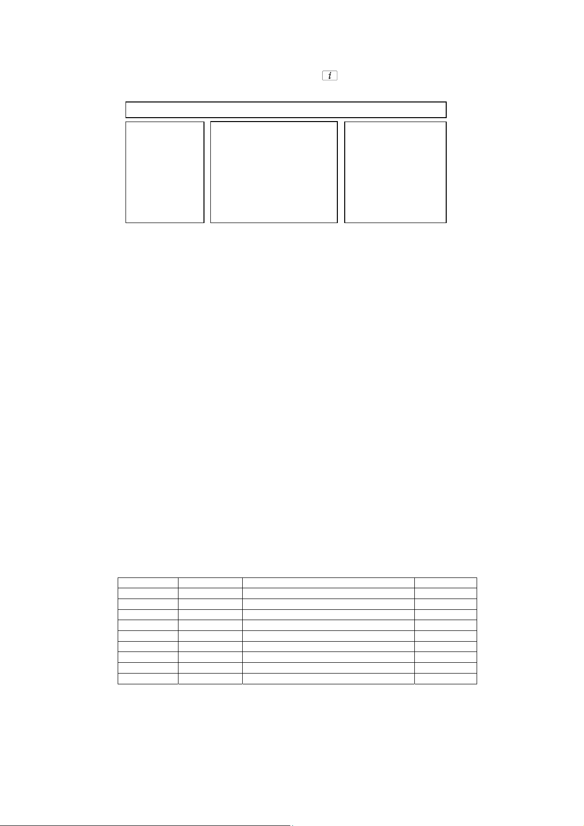
How to enter SERVICE
While pressing (-/v) button on TV unit, press on the remote
control for 3 times within 2 seconds.
Note:
To exit from Service mode, press the exit button on remote control.
0
Page 15

SERVICE
A
A
A
A
A
A
15
SERVICE
ADJUST
WB-ADJ
OPTION
SRV-TOOL
Peaks SOFT 1.901 OPTION 1 04
Peaks EEP 01.00.0001 OPTION 2 ee
LSI PACKAGE 1.721 OPTION 3 01
LSI DATA 1.00.00 OPTION 4 10
STBY SOFT 2.00.00 Model ID 08
STBY EEP 2.01.0000 034e6100
STBY ROMCOR 0.00.00 00000004
R/E Cnt 000/000
INV Cnt 0000
1
ADJUST DYNAMIC
CONTRAST
YMAX
1,2:MAIN SELECT
3,4:SUB SELECT
9 :PICTURE MENU SELECT
YELLOW:AUTO ADJUST
VOL:ADJUST
OK :WRITE
1
WB-ADJ DYNAMIC
R-GAIN
BEFORE
METHOD
COLOR TEMP NORMAL
1,2:MAIN SELECT
3,4:SUB SELECT
7 :COLOR TEMP SELECT
9 :PICTURE MENU SELECT
0 :WB METHOD SELECT
VOL:ADJUST
OK :WRITE/WB DIFF ADJ
1
OPTION DYNAMIC
Boot
1,2:MAIN SELECT
3,4:SUB SELECT
9 :PICTURE MENU SELECT
VOL:ADJUST
1
SRV-TOOL DYNAMIC
000
80
80
02
ROM
00
2
ADJUST DYNAMIC
3
COLOR
1,2:MAIN SELECT
4
3,4:SUB SELECT
9 :PICTURE MENU SELECT
VOL:ADJUST
OK :WRITE
2
WB-ADJ DYNAMIC
G-GAIN
3
BEFORE
METHOD
COLOR TEMP NORMAL
1,2:MAIN SELECT
3,4:SUB SELECT
4
7 :COLOR TEMP SELECT
9 :PICTURE MENU SELECT
0 :WB METHOD SELECT
VOL:ADJUST
OK :WRITE/WB DIFF ADJ
2
OPTION DYNAMIC
STBY-SET
3
1,2:MAIN SELECT
4
3,4:SUB SELECT
9 :PICTURE MENU SELECT
OK :POWER OFF
2
3D
7E
00
7E
02
DJUST DYNAMIC
3
TINT
1,2:MAIN SELECT
4
3,4:SUB SELECT
9 :PICTURE MENU SELECT
VOL:ADJUST
OK :WRITE
WB-ADJ DYNAMIC
B-GAIN
3
BEFORE
METHOD
COLOR TEMP NORMAL
1,2:MAIN SELECT
3,4:SUB SELECT
4
7 :COLOR TEMP SELECT
9 :PICTURE MENU SELECT
0 :WB METHOD SELECT
VOL:ADJUST
OK :WRITE/WB DIFF ADJ
OPTION DYNAMIC
Emergency
3
1,2:MAIN SELECT
4
3,4:SUB SELECT
9 :PICTURE MENU SELECT
VOL:ADJUST
Key Command
Press the 3/4 button to change the adjustment values or function.
Press the 1/2 button to step up/down through the functions and adjustments
Press the numerical button VOLUME (+/-) to change option item.
Press the OK button after each adjustment has been made to store the required values.
ON
00
61
61
02
ADJUST DYNAMIC
3
SUB-BRT
1,2:MAIN SELECT
4
3,4:SUB SELECT
9 :PICTURE MENU SELECT
VOL:ADJUST
OK :WRITE
WB-ADJ DYNAMIC
R-CENT
3
BEFORE
METHOD
COLOR TEMP NORMAL
1,2:MAIN SELECT
3,4:SUB SELECT
4
7 :COLOR TEMP SELECT
9 :PICTURE MENU SELECT
0 :WB METHOD SELECT
VOL:ADJUST
OK :WRITE/WB DIFF ADJ
OPTION DYNAMIC
Y/C Delay
3
1,2:MAIN SELECT
4
3,4:SUB SELECT
9 :PICTURE MENU SELECT
VOL:ADJUST
OK :WRITE
800
82
82
02
DJUST DYNAMIC
3
BACKLIGHT
1,2:MAIN SELECT
4
3,4:SUB SELECT
9 :PICTURE MENU SELECT
VOL:ADJUST
OK :WRITE
WB-ADJ DYNAMIC
G-CENT
3
BEFORE
METHOD
COLOR TEMP NORMAL
1,2:MAIN SELECT
3,4:SUB SELECT
7 :COLOR TEMP SELECT
9 :PICTURE MENU SELECT
0 :WB METHOD SELECT
VOL:ADJUST
OK :WRITE/WB DIFF ADJ
OPTION DYNAMIC
OPT 1
3
1,2:MAIN SELECT
4
3,4:SUB SELECT
5,6:BIT SELECT
9 :PICTURE MENU SELECT
VOL:ADJUST
OK :WRITE
26C
80
80
02
00000100
DJUST DYNAMIC
H-POS
3
1,2:MAIN SELECT
4
3,4:SUB SELECT
9 :PICTURE MENU SELECT
VOL:ADJUST
OK :WRITE
WB-ADJ DYNAMIC
B-CENT
3
BEFORE
METHOD
COLOR TEMP NORMAL
1,2:MAIN SELECT
3,4:SUB SELECT
4 4
7 :COLOR TEMP SELECT
9 :PICTURE MENU SELECT
0 :WB METHOD SELECT
VOL:ADJUST
OK :WRITE/WB DIFF ADJ
OPTION DYNAMIC
OPT 2
3
1,2:MAIN SELECT
4
3,4:SUB SELECT
5,6:BIT SELECT
9 :PICTURE MENU SELECT
VOL:ADJUST
OK :WRITE
11101110
8F
02
8F
DJUST DYNAMIC
0
H-AMP
3
1,2:MAIN SELECT
4
3,4:SUB SELECT
9 :PICTURE MENU SELECT
VOL:ADJUST
OK :WRITE
OPTION DYNAMIC
OPT 3
3
1,2:MAIN SELECT
4
3,4:SUB SELECT
5,6:BIT SELECT
9 :PICTURE MENU SELECT
VOL:ADJUST
OK :WRITE
0
00000001
ADJUST DYNAMIC
V-POS
3
1,2:MAIN SELECT
4
3,4:SUB SELECT
9 :PICTURE MENU SELECT
VOL:ADJUST
OK :WRITE
OPTION DYNAMIC
OPT 4
3
1,2:MAIN SELECT
4
3,4:SUB SELECT
5,6:BIT SELECT
9 :PICTURE MENU SELECT
VOL:ADJUST
OK :WRITE
00010000
DJUST DYNAMIC
0
V-AMP
3
1,2:MAIN SELECT
4
3,4:SUB SELECT
9 :PICTURE MENU SELECT
VOL:ADJUST
OK :WRITE
4
DJUST DYNAMIC
VCOM
BEFORE
1,2:MAIN SELECT
3,4:SUB SELECT
5 :FLICKER PATTERN
9 :PICTURE MENU SELECT
VOL:ADJUST
OK :WRITE
OPTION DYNAMIC
EDID-CLK
3
HDMI
1,2:MAIN SELECT
4
3,4:SUB SELECT
7 :HDMI SELECT
9 :PICTURE MENU SELECT
VOL:ADJUST
OK :WRITE
3
1A9
1A9
MID
1
0
1,2:MAIN SELECT
9 :PICTURE MENU SELECT
OK :ENTER
Page 16

Service Tool Mode
16
How to access
1. Select [SRV-TOOL] in Service Mode.
2. Press [OK] button on the remote control.
Display of TD2Microcode version
Display of Flash ROM maker code
Display of SOS History
SRV-TOOL
TD2Microcode:005a0910
Flash ROOM: AD – F1
PTCT:00.00.00.00.00 Time 00051:30 On/Off 0000042
Display of SOS History
SOS History (Number of LED blinking) indication.
From left side; Last SOS, before Last, three occurrence before, 2
This indication will be cleared by [Self/check indication and forced to factory shipment setting].
nd
occurrence after shipment, 1st occurrence after shipment.
Power ON Time, On/Off
Note: To display TIME/COUNT menu, highlight position, then press MUTE for 3sec.
Time: Cumulative power on time, indicated hour: minute by decimal.
On/Off: Number of On/Off switching by decimal.
Note: This indication will not be cleared by either of the self-checks or any other command.
Exit
Disconnect the AC cord from wall outlet or switch off the power with [Power] button on the main unit.
POWER ON TIME/COUNT
Press [MUTE] button (3sec)
Page 17

Hotel Mode
17
1. Purpose
Restrict a function for hotels.
2. Access command to the Hotel mode setup menu.
In order to display the Hotel mode setup menu,
please enter the following command (within 2 second).
[TV] : Vol.[Down] + [REMOTE] : AV (3 times)
Then, the Hotel mode setup menu is displayed.
Hotel mode
Hotel mode
Initial INPUT
Initial POS
Off
Off
Off
Initial VOL Level
Maximum Vol Level
Button Lock
Remote Lock
Off
Off
Off
Off
Select
EXIT
Change
RETURN
3. To exit the Hotel mode setup menu.
Disconnect AC power cord from wall outlet.
4. Explain the Hotel mode setup menu.
ITEM Function
Hotel Mode Select hotel mode ON/OFF
Initial INPUT Select input signal modes.
Initial POS Select programme number.
Initial VOL Level Adjust the volume when each time power is
Maximum VOL
Level
Button Lock Select local key conditions.
Remote Lock Select remote control key conditions.
Set the input, when each time power is switched on.
Selection:
Off Analog /DVB-C/DVB-T/ AV1/AV2
Component/HDMI1/HDMI2
*Off: give priority to the last memory. However, Euro
Model is compulsorily set to TV.
*AVnS/AVnC: only Euro model selectable
* PC:selectable with VGA option
Selection:
Off/0 to 99
*Off: give priority to the last memory
switched on.
Selection/Range:
Off/0 to 100
*Off: give priority to the last memory
Adjust maximum volume.
Range:
0 to 100
Selection:
Off/SETUP/MENU/ALL
*Off: altogether valid
*Setup: only F-key is invalid
(Tuning guide (menu) can not be selected.)
*MENU: only F-key is invalid
(only Volume/Mute can be selected.)
*All: altogether invalid.
Selected”
Off/SETUP/MENU
*Off: altogether valid
*Setup: only Setup menu is invalid
MENU: Picture/Sound/Setup menu are invalid
Page 18
Data Copy by SD Card
18
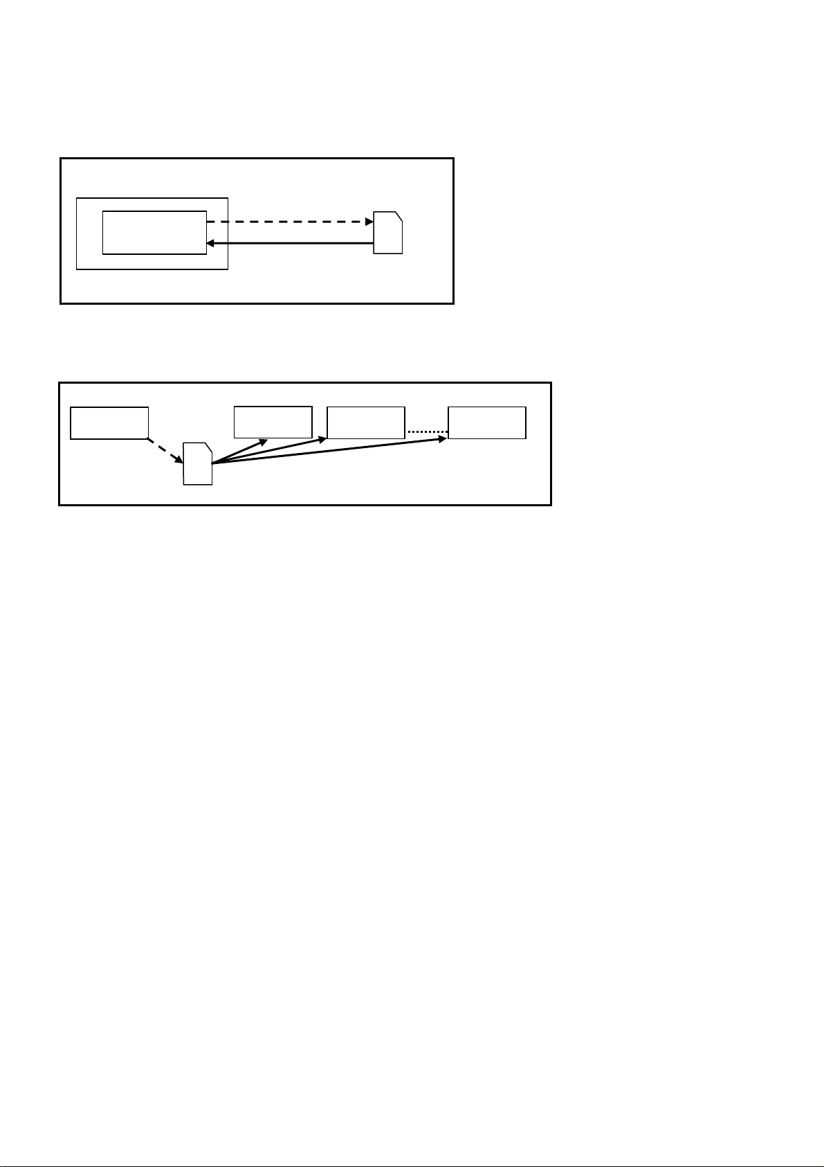
Purpose
a) Board replacement (Copy the data when exchanging A-board):
When exchanging A-board, the data in original A-board can be copied to SD card and then copy to new A-board.
TV
A-board
(Before exchanging)
Copy to SD card
(After exchanging)
Copy back from SD card
SD
Following data can be copied.
User setting data
(inc. Hotel mode setting data)
Channel scan data
Adjustment and factory preset data
b) Hotel (Copy the data when installing a number of units in hotel or any facility):
When installing a number of units in hotel or any facility, the data in master TV can be copied to SD card and the copy
to other TVs.
Master TV
Copy to SD card
SD
Other TV
Copy from SD card
Other TV
Other TV
Following data can be copied.
User setting data
(inc. Hotel mode setting data)
Channel scan data
Preparation
Make pwd.file as startup file for (a) or (b) in an empty SD card.
1. Insert an empty SD card to your PC.
2. Right-click a blank area in a SD card window, point to New, and then click text document. A new file is created by
default (New Text Document.txt).
3. Right-click the new text document that you just created and select rename, and then change the name and extension
of the file to the following file name (a) or (b) and press ENTER.
File name:
(a) For Board replacement: boardreplace.pwd
(b) For Hotel: hotel.pwd
Note:
Please make only one file to prevent the operation error.
No any other file should be in SD card.
Page 19
Data Copy from TV set to SD Card
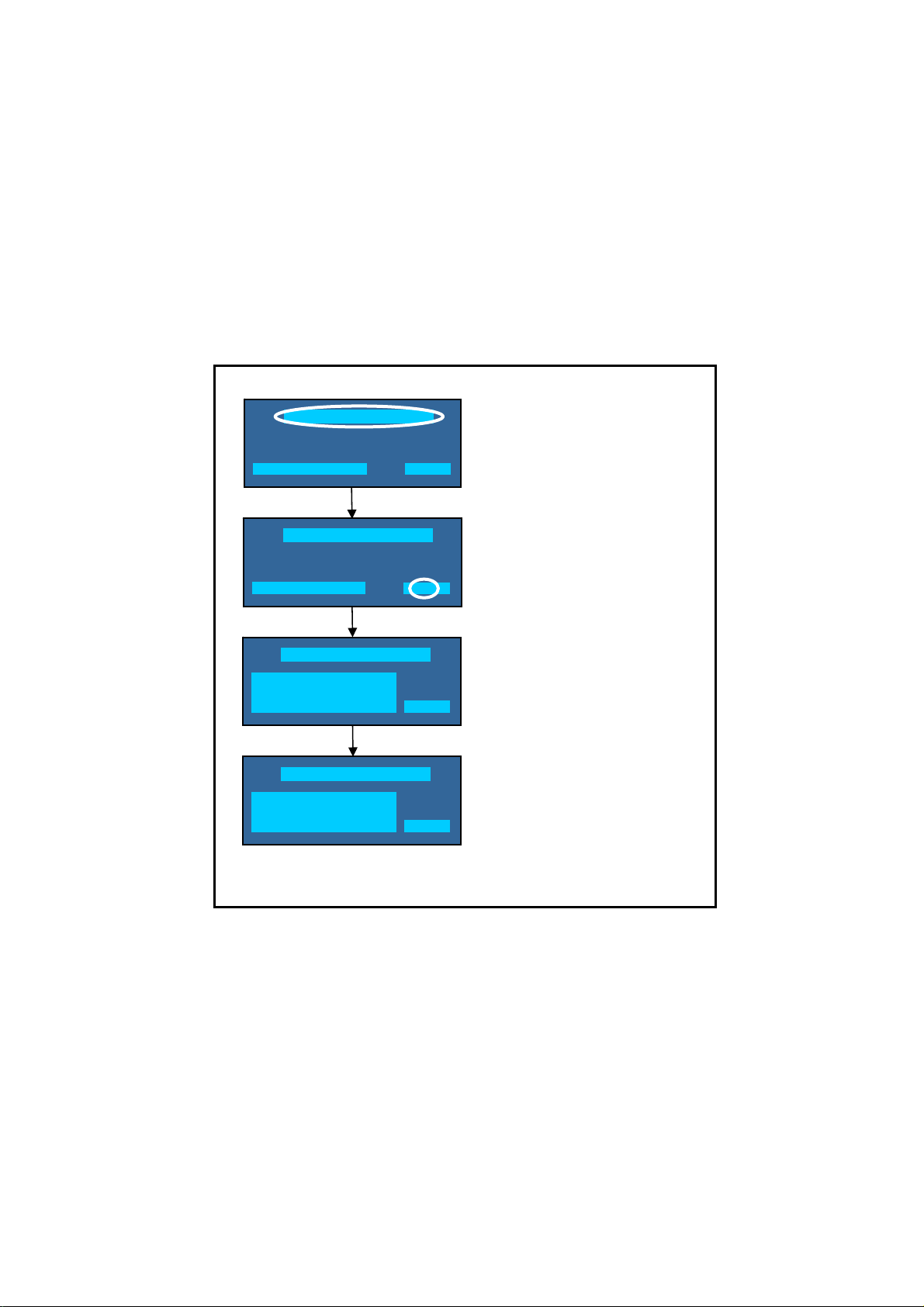
19
1. Turn on the TV set.
2. Insert SD card with a startup file (pwd.file) to SD slot.
On-screen Display will be appeared according to the startup file automatically.
3. Input a following password for (a) or (b) by using remote control.
(a) For Board replacement: 2770
(b) For Hotel: 4850
Data will be copied from TV set to SD card.
It takes around 2 to 6 minutes maximum for copying.
4. After the completion of copying to SD card, remove SD card from TV set.
5. Turn off the TV set.
Note:
Following new folder will be created in SD card for data from TV set.
(a) For Board replacement: user_setup
(b) For Hotel: hotel
Please do not remove the SD card
Data copy has been successful
Data Copy(Board replacement )
Input password
Data Copy(Board replacement )
Input password
Data Copy(Board replacement )
Copy TV to SD card
Please wait for a while
Data Copy(Board replacement )
Performing
Please remove SD card
Data copy
(Board replacement) or (Hotel)
-----
Input Password
2770 or 4850
-----
Performing
GETTING
Completion
FINISH
Page 20

Data Copy from SD Card to TV set
20
1. Turn on the TV set.
2. Insert Sd card with Data to SD slot.
On-screen Display will be appeared according to the Data folder automatically.
3. Input a following password for (a) or (b) by using remote control.
(a) For Board replacement: 2771
(b) For Hotel: 4851
Data will be copied from SD card to TV set.
4. After the completion of copying to SD card, remove SD card from TV set.
(a) For Board replacement: Data will be deleted after copying (Limited one copy).
(b) For Hotel: Data will not be deleted and can be used for other TVs.
5. Turn off the TV set.
Note:
1. Depending on the failure of boards, function of Data for board replacement does not work.
2. This function can be effective among the same model numbers.
Data Copy(Board replacement )
Input Password
Input password
Performing
Data Copy(Board replacement )
Copy SD card to TV
Please wait for a while
Please do not remove the SD card
Data Copy(Board replacement )
Performing
Data copy has been successful
Please remove SD card
Input Password
2771 or 4851
-----
Performing
WRITING
Completion
FINISH
Page 21

Option Bytes Description
21
OPTION1
OPTION2
OPTION3
OPTION4
b1 TEXT Ch Refresh ON (1) / OFF (0)
b2 ID-1 ON (1) / OFF (0)
b3 Macrovision A uto-ju dge ON (1) / OFF (0)
b4 Surround enab le low bit ON (1) / OFF (0)
b5 Surround enab le high bit ON (1) / OFF (0)
b7 TINT_Compo nent_HDMI ON (1) / OFF (0)
b0 Adjust gain en able ON (1) / OFF (0)
b1 A2 BG enable (5.5MHz) ON (1) / OFF (0)
b2 A2 DK1 enable (6.26MHz) ON (1) / OFF (0)
b3 A2 DK3 enable (5.742MHz) ON (1) / OFF (0)
b4 NICAM scan ON (1) / OFF (0)
b5 NICAM BG enable (5.5MHz) ON (1) / OFF (0)
b6 NICAM I enable (6.0MHz) ON (1) / OFF (0)
b7 NICAM DK enable (6.5MHz) ON (1) / OFF (0)
b0 NICAM priority ON (1) / OFF (0)
b1 Starhub scan enab le (Singapore) ON (1) / OFF (0)
b3 A2 DK2 enable ON (1) / OFF (0)
Inhibition of countermeasure
b4
for SIF signal drop
b6 SSU search enable for HOTEL model ON (1) / OFF (0)
b2 3DYC color motion detect ON (1) / OFF (0)
b4 SHOP banner enable ON (1) / OFF (0)
b6 PIP ON (1) / OFF (0)
ON (1) / OFF (0)
Page 22

Adjustment Method
22
Sub-Contrast/White Balance Adjustment
Instrument Name Connect to Remarks
1. Remote controller
2. LCD WB meter (Minolta CS-1000A equivalent)
3. Comunication jig
4. Computer for external control
Procedure Remarks
Subcontrast adjustment
1. Receive PAL colour bar (100% white) RF signal.
2. Enter “Contrast” adj. In SERVICE mode.
3. Start adjusting by using Yellow Key.
4. If the adjustment finished normally, the letter of Contrast will change from red
to black
White Balance adjustment
1. Procedure basically performs checking using the production software and
make automatic adjustment using external computer.
2. It adjusts in the mode of : Colour balance Normal as follows.
Viewing Mode Dynamic
WHITE Normal
x: 0,2990 0,010
y: 0,3110 0,010
GRAY Normal
x: 0,2990 0,010
y: 0,3110 0,010
Correlation can be also taken by
CA-210 or equivalent
Let the panel standfor more than 3
hours at more than 20 C.
Basically perform adjustment in the
ambient environment of room
temperature more than 20 C.
The aging time is more than 20 min
at above room temperature.
Applied signal
100% full colour bar
0,7V p-p white peak
85% modulation
100% WHITE
50% GRAY
Page 23

Wiring Diagram
23
TUNER
TU4801
A14
LCD PANEL
P5
P6
P7
P8
P1 MAIN IN
CI SLOT
DIGITAL
AUDIO OUT
SERVICE
HDMI2
HDMI1
JK1070
D3050
CN0100
JK1021
JK1020
Rear Terminals
A-BOARD
A09
A10
A02
P2
P-BOARD
KA10
KA-BOARD
GK1
KEY CONTROL
GK-BOARD
YUV,V IN,
AUDIO IN
RCA
JK1001
JK1003
AV scart
A12
SP
JK8850
Side Terminals
JK1052
SD SLOT
HP
Page 24

Block Diagram (1/2)
24
SP_L
SP_R
A-BOARD
1
2
3
6
7
11
15
JK1003
19
AV2 21PIN SCART
20
V
Y,PB,PR
JK1001
AUDIO
IN
L
R
JK1052
A02
SG_KEY3
1
KEY
3
TO GK1
A09
STB5.8V
8
P15V
11,12,13
5.8VS
15
PWM_A_OUT
3
TO P2
4
5
9
BL_ON
BL_SOS
LCD_TV_SUB_ON
AV2 _ROUT
AV2_R
AV2_LOUT
AV2_L
AV2_BLUE
AV2_GREEN
AV2_RED
AV2_VOUT
AV2_V
CVBS
Y
PB
PR
PC_LIN
PC_RIN
HP_LOUT
HP_ROUT
IC1951
2
Vin
DETECTOR
IIC3
VOLTAGE
4
Vo
53
R2out
R4in
65
L2out
54
L4in
64
B2/Cin2
15
13
G2/Yin2
R2/Cin1
11
Y/Y+C/CVBSout4
38
SAG_CVBSout4
37
CVBS IN
17
CVBS
7
CYin1
95
PBin1
93
PRin1
97
L7in
70
71
R7in
STB_RST
18,24,
36,86
IC3001
AV-SWITCH
[C1AB00003384]
45,80
96
16V
P15V
CVBS
MAIN_Y/CVBS
MAIN_PB/C
MAIN_PR
RGB_CVBS
L1IN
R1IN
L2IN
R2IN
L4out
R4out
SUB3.3V
SUB9V
SUB5V
31
33
35
46
34
32
58
59
60
61
50
49
L4150
20
Vin
2
Vin
2
Vin
5
IC8100
DC/DC
IC8701
REG
IC8700
REG
TU4801
TUNER DVB-T/C
5
11
12
13
IF_AGC
SIF
AC_TV1_V
TCON15.6V
SUB1.2V
4
SUB1.5V
Vo
9
SUB5V
3
Vo
SUB3.3V
3
Vo
4
IFD_OUT2
IFD_OUT1
MAIN_Y/CVBS
P15V
TCON15.6V
STB5.8V
SUB3.3V
SUB5V
KEY
10
6
SUB3.3V
SUB1.8V
MAIN_PB/C
MAIN_PR
RGB_CVBS
VIN
HIN
AUDIOOUT_L
AUDIOOUT_R
TV_L
TV_R
AV_L
AV_R
2
4
Vin
6
Vin
4
Vin
1
Vin
SUB5V
IC5416
IC8702
IC8706
IC8404
REG
REG
REG
REG
L4150
D4168
Vo
Vo
Vo
Vo
IIC0
5
1
3
5
TCON15.6V
VON31V
STB5V
SUB1.8V
HDMI3.3V
SUB_CI_5V
STB_RST
HDMI_CEC
TUNER I/F
AE10
AC9
AB15
AA16
AB16
AB14
AA10
AC10
AF13
AB13
AC12
AB12
AC14
AA13
AD13
AE13
HPD0
HDMI 1
JK1020
STMDDCSDA0
STMDDCSCL0
SD CARD SLOT
SUB3.3V
SUB1.5V
IC8201
DDR 3
P_STM5VDET0
JK8850
SUB3.3V
IC8902
EEPROM
sLD2
IIC I/F
IIC I/F
HDMI I/F
HPD1
HPD0
HDMI_CEC
SD CARD I/F
HDMI_CEC
STMDDCSCL0
P_STM5VDET0/1
HPD1
STMDDCSCL1
STMDDCSDA1
STMDDCSDA0
STMDDCSDA1
STMDDCSCL1
HDMI 2
JK1021
L+
1 2 3 4
A12
33,34
8
STB1.2V
VDDSD18V33V
V5 V6
REMOTE
P_STTCECAUL13
P_STM5VDET1
L-
28,29
21,22
IC4900
MAIN AUDIO
AMPLIFIER
[C1AB00003457]
9
[MN2WS0177C]
A-Chip
STM
RESET
REMOTE
KEY
STB_RST
LCD_TV_SUB_ON
OPT_SPDIF
OPT_SPDIF
R-
R+
26,27
19,20
35,36
11
10
SUB1.5V
Y3 Y2
IC8000
SLD2
D-Chip
COMMON PORT
BL_ON
BL_SOS
PWM_A_OUT
P15V
5.8VS
SUB3.3V
SUB9V
ARC SW
CN0100
SERVICE
P15V
HDMI3.3V
SUB1.2V
SUB1.8V
R_LED
G_LED
SOS_SENSE
Digital
Audio Out
D3050
SUB5V
STB3.3V
TCON2.5V
PANEL_ON
AVDO_ENB
STB_RST
28
1
2
6
14
32
SUB5V
SUB3.3V
STB3.3V
G_LED
R_LED
REMOTE
TCON15.6V
IIC0
ARC_OFF
IC5000
ANALOG ASIC
[ANA34043A-VF]
3031
STB1.2V
STB3.3V
STB5V
CPU
AUDIO OUTPUT
RESET
12
13 8
18
SOS_SENSE
PWM_A_OUT
A10
3
2
1
5
9,10,
IC4150
15,31,
32
[C0DBAYY00868]
18 17
PANEL_ON
COMMON PORT
TV_SUB_ON
KA10
3
2
1
5
DC/DC
AVDO_ENB
TCON
LVDS I/F
SYSTEM BUS
FLASH I/F
SUB_CI_5V
17,18
51,52
CI SLOT
JK1070
STB3.3V
G_LED
R_LED
REMOTE
1,2,
23,27
8,7
14
SOS_SENSE
IC8403
TRANSCEIVER
[C0JBAZ003032]
20
SUB3.3V
Q2801
Q2800
AVDD12.6V
DVDD2.5V
DVDD2.5V
9
IC4120
TCON GAMMA DAC
[C0FBBY000086]
17
LD
IC8900
MEMORY
SUB3.3V
DVDD2.5V
AVDD12.6V
AVDD12.6V
7
FLASH
KA-BOARD
D2800A
LED
RM2800
LED RECIEVER
VON31V
Q4150
VOFF2_6V
Q4151
IIC0
VRF1;VRF2;VRF3
VRF4;VRF5;VRF6
VRF8;VRF9;
VRF10;VRF11;
VRF12;
VCOM
IIC0
A14
11-12
49-52
7
6
48,47,46
45,44,43
42,41
40,39
38
53,54
17,18,20
21,23,24
26,27,29
30,32,33,
35,36
4
TO LCD PANEL
Page 25

Block Diagram (2/2)
MAIN IN
Line
Line
25
TO A09
T7302
R7513
Q7503
P2
7
3,4,5
16V
TV_SUB_ON
8
1
5VSTUNER6V,
RELAY
Q7504
11
10
INV_ON
INV_PWM
10213
STB
PWM_IN
9
INV_SOS
FAIL
N2
17
T7801
N1
18
CONTROL
IC7801
LED DRIVER
COMP
15
COMPSD
VS
7
14
IS
6
IC7501
D7506
8
9
10
1
376
PC7301
R7505
PC7302
PC7303
Q7803
Q7804
HOT COLD
CF7101
3
4
LF7103
3
4
LF7102
3
D7205
1
T7201
3
1
D7102
4
T7802
T7803
2
5
VH
D7315
2
1
Filter
2
1
Filter
2
8
IC7301
Q7201
OUT
PWM IC
FB
D7309
VCC
7
Q7301
7
8
OUT
D7303
D7302
POWER
IC7201
CONTROL
VCC
Q7303 Q7302
D7808
D7806
P5
P6
D7807
D7809
P7
T7804
P8
P-BOARD
P1
F7101
2
1
Page 26

Parts Location
26
The numbers on the exploded view below refer to the exploded view section of the Replacement Parts List.
19
17
9
6
2
4
NOTE:
10
8
7
Page 27

27
The numbers on the exploded view below refer to the exploded view section of the Replacement Parts List.
NOTE:
13
20
11
14
16
18
3
5
15
12
5
1
Page 28

Replacement Parts List
28
Components Identified by mark have special characteristics important for safety.
In case of ordering these spare parts, please always add the complete Model-Type number to your order.
RTL (Retention Time Limited)
Note:
* When replacing any of these components, use only manufacturers specified parts.
The marking (RTL) indicates that the Retention Time is Limited for this item. After the
discontinuation of this assembly in production, the item will continue to be available for
a specific period of time. The retention period of availability is dependent on the type of
assembly, and in accordance with the laws governing part and product retention. After
the end of this period, the assembly will no longer be available.
Important Safety Notice
X
The marking (X) indicates that board should be exchanged for service.
DescriptionCct Ref Parts Number DescriptionCct Ref Parts Number
EXPLODED VIEW
A P.C.B. 1 A-L32C4E
BATTERY COVER OF RC 2 BAT-C-0487
TUNER DVB-T/T2/C 3 ENGS7302D5F
AC CORD 4 K2CQ2YY00085
SPEAKER UNIT 5 L0AA10B00003
REMOTE CONTROL 6 N2QAYB000487
PEDESTAL ASSY 7 TBL5ZX0213
PEDESTAL ASSY FIX 8 TBL5ZX0214
MODEL LABEL 9 TBM0E2716
CONNECTOR COVER 10 TKP0E16001
VESA TOP 11 TKZ0EX5014
BOTTOM BRACKET 12 TKZ4GX5105
P P.C.B. 13 TNP4G508AF
GK P.C.B. 14 TNP4G514AC
KA P.C.B. 15 TNP4G517AC
SIDE AV BRACKET 16 TTP0E0118
BACK COVER ASSY 17 TTU0E1025
HEAT SINK 18 TUC4GJ5055
CABINET ASSY 19 TXFKY5Z0209
LCD PANEL 20 VVX32H121G00
MISCELLANEOUS COMPONENTS
BATTERY . R6DB/2P
SCREW . THEJ036J
IR LED WINDOW . TKK0E9344
FELT . TMK0E040
FELT . TMK0E089
FELT . TMK0E090
FELT . TMK0EA198
FELT . TMK0EA250
FELT . TMK0EA285
SPEAKER SPONGE . TMK0EG059
SPEAKER RUBBER BUSH. TMM4GJ004
CARTON . TPC0EA09301
TOP CUSHION . TPD0E1188
BOTTOM CUSHION . TPD0E2192
BAG . TPE0E9008
CARTON CAP . TPG0E9850
HEAT SINK . TUC4GC5042
HEAT SINK . TUC4GJ5058
SCREW . XTV3+12JFJ
SCREW .XYN3+J8FJ
SCREW . XYN4+F12FJK
CLAMPER CK301 TMME268
INSTRUCTION BOOKS
GERMAN . TQB0E2177A
DUTCH . TQB0E2177B
ITALIAN . TQB0E2177C
FRENCH . TQB0E2177D
RTL
X
RTL
RTL
RTL
SPANISH . TQB0E2177E
SWEDISH . TQB0E2177F
NORWEGIAN . TQB0E2177G
FINNISH . TQB0E2177H
LITHUANIAN . TQB0E2177I
PORTUGUESE . TQB0E2177J
DANISH . TQB0E2177K
BULGARIAN . TQB0E2177M
ROMANIAN . TQB0E2177N
LATVIAN . TQB0E2177O
POLISH . TQB0E2177P
HUNGARIAN . TQB0E2177Q
CZECH . TQB0E2177R
GREEK . TQB0E2177S
TURKISH . TQB0E2177T
ENGLISH . TQB0E2177U
CROATIAN . TQB0E2177V
SLOVAKIAN . TQB0E2177W
CD . TQB0E2177X
ESTONIAN . TQB0E2177Z
I.C.s
RESET IC IC1951 C0EBF0000354
AUDIO VIDEO SWITCHIC3001 C1AB00003384
TCON GAMMA DAC IC4120 C0FBBY000086
DC/DC CONVERTER IC4150 C0DBAYY00868
AUDIO AMPLIFIER IC4900 C1AB00003457
ANALOG ASIC IC5000 AN34043AAVF
REGULATOR IC5416 C0DBGYY00281
POWER FACTOR CONTROLIC7201 C0DBBYY00033
PWM CONTROLLER IC7301 C0DABYY00034
REGULATOR IC7501 C0DBZYY00486
LED DRIVER CONTROL ICIC7801 C0DBZYY00413
PEAKS_SLD2 IC8000 MN2W S0177C
DC/DC CONVERTER IC8100 C0DBAYY00715
DDR SDRAM IC8201 C3ABTY000059
BUFFER IC8403 C0JBAZ003032
POWER SWITCH IC IC8404 C0DBZYY00382
REGULATOR IC8700 C0DBAYY00915
REGULATOR IC8701 C0DBAYY00915
REGULATOR IC8702 C0DBAFG00029
REGULATOR IC8706 C0DBGYY00887
NAND FLASH MEMORYIC8900 TVR4G238-AB
EEPROM STM IC8901 STML32C4E
EEPROM SLD2 IC8902 X24CL32C4E
PHOTO COUPLER PC7301 B3PAA0000363
PHOTO COUPLER PC7302 B3PAA0000363
PHOTO COUPLER PC7303 B3PAA0000363
Page 29

FUSES
29
DIODES
DescriptionCct Ref Parts Number DescriptionCct Ref Parts Number
RC RECEIVER RM2800 PNJ4815M01TV
FUSE HOLDER F7101-2 K3GE1ZZ00001
FUSE HOLDER F7101-1 K3GE1ZZ00001
FUSE F7101 K5D502BNA005
FUSE PA4150 K5H1622A0031
FUSE PA4151 ERBSE1R50U
FUSE PA4152 ERBSE1R50U
FUSE PA7551 K5H502YA0063
DIODE D0917 DZ2J062M0L
DIODE D1951 B0JCCE000008
DIODE D1952 DA2J10100L
DIODE D1953 DA2J10100L
DIODE D1954 DA2J10100L
DIODE D1955 B0JCCE000008
VARISTOR D2005 EZJZ0V120JA
VARISTOR D2007 EZJZ0V120JA
LED D2800 B3AGB0000060
DIODE D3130 B0ACCJ000048
DIODE D4001 DA2J10100L
DIODE D4150 B0JCDE000006
DIODE D4151 B0JDCE000017
DIODE D4152 B0JCDE000006
DIODE D4153 B0JCDE000006
DIODE D4154 B0JCDE000006
ZENER DIODE D4155 B0BC03200003
DIODE D4156 DA2J10100L
DIODE D4157 DA2J10100L
DIODE D4159 B0JCDE000006
DIODE D4160 B0JCDE000006
DIODE D4161 B0JCDE000006
DIODE D4162 B0JCDE000006
DIODE D4163 DZ2J200M0L
ZENER DIODE D4165 B0BC01000035
DIODE D4166 DA2J10100L
DIODE D4167 DA2J10100L
DIODE D4168 DA2J10100L
DIODE D4169 B0BC4R700020
ZENER DIODE D4170 DZ2J047M0L
DIODE D4171 DA2J10100L
DIODE D4172 B0JCPE000004
DIODE D4173 B0BC01700030
ZENER DIODE D4174 B0BC022A0007
DIODE D4175 DA2J10100L
DIODE D4500 B0JCCE000008
DIODE D4604 B0JCCD000020
DIODE D5172 B0BC01700015
DIODE D5173 DA2J10100L
DIODE D5174 B0BC010A0007
DIODE D5175 DA2J10100L
ZENER DIODE D5180 DZ2J033M0L
DIODE D5480 B0JCCE000008
DIODE D7101 D4EAY6210003
DIODE D7102 B0FBAT000021
DIODE D7103 D4EAY6210003
DIODE D7203 B0ECKM000038
DIODE D7204 B0BC015A0336
DIODE D7205 B0EAMR000020
ZENER DIODE D7207 DZ2J068M0L
DIODE D7208 DA2J10100L
DIODE D7209 DA2J10100L
DIODE D7302 B0HAGQ000001
DIODE D7303 B0HAGQ000001
ZENER DIODE D7304 DZ2J068M0L
DIODE D7309 B0ECKM000038
DIODE D7310 B0BC015A0336
TRANSISTORS
TRANSFORMERS
DIODE D7314 B0BC015A0336
DIODE D7315 B0BB140A0011
DIODE D7317 B0BC027A0336
DIODE D7318 B0BC015A0336
DIODE D7319 B0ECKM000038
DIODE D7503 B0HESM000002
DIODE D7504 DZ2J220M0L
DIODE D7505 B0HAMM000108
DIODE D7507 DA2J10100L
DIODE D7801 B0ADCK000001
DIODE D7806 DA6X103Q0R
DIODE D7807 DA6X103Q0R
DIODE D7808 DA6X103Q0R
DIODE D7809 DA6X103Q0R
DIODE D7810 B0ADCK000001
DIODE D7811 B0JCKG000002
DIODE D7812 B0JCKG000002
DIODE D7813 B0BC015A0336
ZENER DIODE D7814 DZ2J150M0L
ZENER DIODE D8703 B0BC6R600005
ZENER DIODE D8705 B0BC6R600005
DIODE D8716 DA2J10100L
DIODE D8720 B0JCMD000066
TRANSISTOR Q0900 B1ADCF000194
TRANSISTOR Q1951 B1ADCF000194
TRANSISTOR Q2001 DSC2001S0L
TRANSISTOR Q2002 B1ADGJ000008
TRANSISTOR Q2800 DSC200100L
TRANSISTOR Q2801 DSC200100L
TRANSISTOR Q2802 DSC200100L
TRANSISTOR Q3102 B1ABCF000231
TRANSISTOR Q3103 B1ABCF000231
TRANSISTOR Q4150 DSC500100L
TRANSISTOR Q4151 DSA500100L
TRANSISTOR Q4152 DSA500100L
TRANSISTOR Q4153 B1ABCF000231
TRANSISTOR Q4154 B1CFQD000001
TRANSISTOR Q4600 B1ABCF000231
TRANSISTOR Q4604 B1ABCF000231
TRANSISTOR Q4750 B1HFCFA00026
TRANSISTOR Q4751 DSA200100L
TRANSISTOR Q4971 B1AAFB000004
TRANSISTOR Q4972 B1AAFB000004
TRANSISTOR Q4973 DSA2001S0L
TRANSISTOR Q4974 DSC2001S0L
TRANSISTOR Q7201 B1CERR000057
TRANSISTOR Q7202 B1ADCE000027
TRANSISTOR Q7203 B1ABBE000003
TRANSISTOR Q7301 B1ADCE000027
TRANSISTOR Q7302 B1ADCE000027
TRANSISTOR Q7303 B1ABBE000003
TRANSISTOR Q7306 B1DFDD000019
TRANSISTOR Q7501 B1ABBE000003
TRANSISTOR Q7502 B1ABBE000003
TRANSISTOR Q7503 B1CHRE000008
TRANSISTOR Q7504 B1CHRE000008
TRANSISTOR Q7505 B1ABBE000003
TRANSISTOR Q7801 B1ADCE000027
TRANSISTOR Q7802 B1ADCE000027
TRANSISTOR Q7803 B1CFRR000016
TRANSISTOR Q7804 B1CFRR000016
TRANSISTOR Q8100 B1MBEDA00027
TRANSISTOR Q8102 B1MBEDA00027
TRANSFORMATOR T7201 G4DYA0000339
TRANSFORMATOR T7302 G4DYA0000338
Page 30

COILS
30
DescriptionCct Ref Parts Number DescriptionCct Ref Parts Number
TRANSFORMATOR T7801 G4DYA0000335
TRANSFORMER T7802 G4FYA0000020
TRANSFORMER T7803 G4FYA0000020
TRANSFORMER T7804 G4EYA0000037
COIL L2001 J0JYC0000065
COIL L2750 J0JYC0000065
COIL L2752 J0JYC0000065
COIL L2754 J0JYC0000065
COIL L3002 G1C100MA0072
CHIP INDUCTOR L3102 J0JYC0000331
CHIP INDUCTOR L3103 J0JYC0000331
COIL L3108 J0JCC0000287
CHIP INDUCTOR L3111 J0JYC0000331
CHIP INDUCTOR L3112 J0JYC0000331
CHIP INDUCTOR L3113 J0JYC0000331
CHIP INDUCTOR L3116 J0JYC0000331
CHIP INDUCTOR L3117 J0JYC0000331
CHIP INDUCTOR L3118 J0JYC0000331
COIL L3121 J0JCC0000287
COIL L4150 J0JHC0000046
COIL L4151 G1C100MA0426
COIL L4152 J0JHC0000077
COIL L4153 G1C220MA0234
COIL L4200 J0JHC0000046
CHIP INDUCTOR L4700 J0JYC0000068
CHIP INDUCTOR L4701 J0JYC0000068
CHIP INDUCTOR L4702 J0JYC0000068
CHIP INDUCTOR L4703 J0JYC0000068
COIL L4800 G1CR39J00009
COIL L4801 G1CR39J00009
COIL L4802 J0JGC0000020
COIL L4803 J0JGC0000020
COIL L4804 J0JGC0000020
CHIP INDUCTOR L4808 J0JCC0000278
COIL L4900 G1C150MA0426
COIL L4901 G1C150MA0426
COIL L4902 G1C150MA0426
COIL L4903 G1C150MA0426
COIL L4904 J0JHC0000078
COIL L4905 J0JHC0000078
COIL L4906 J0JHC0000078
COIL L4907 J0JHC0000078
FILTER L7101 J0JKB0000034
FILTER L7102 J0JKB0000034
FILTER L7104 J0JKB0000034
FILTER L7105 J0JKB0000034
FILTER L7201 J0JKB0000034
FILTER L7301 J0JKB0000034
FILTER L7302 J0JKB0000034
COIL L7303 J0JKA0000038
COIL L7803 J0JKA0000038
FILTER L7804 J0JKB0000034
FILTER L7808 J0JKB0000034
FILTER L7809 J0JKB0000034
COIL L8003 J0JCC0000287
C
OIL B
COIL BLM18PG121SN1DL8006 J0JHC0000045
COIL BLM18PG121SN1DL8007 J0JHC0000045
COIL L8009 J0JKC0000021
COIL L8015 J0JCC0000287
COIL L8016 J0JCC0000287
COIL L8100 G1C4R7MA0416
COIL L8102 G1C3R3MA0425
FILTER L8641 J0JBC0000115
COIL L8700 G1C6R8MA0416
COIL L8701 G1C100MA0416
LM18PG121SN1DL8005 J0JHC0000045
FILTERS
CRYSTALS
RESISTORS
GA220JA023 .063W 5% 22 Ω
FILTER FL4000 EXC28CE201U
FILTER FL4001 EXC28CE201U
FILTER FL4002 EXC28CE201U
FILTER FL4006 EXC28CE201U
LINE FILTER LF7102 G0B103H00010
LINE FILTER LF7103 G0B103H00010
CRYSTAL X8300 H0J245500113
THERMISTCF7101 D4CAY3R9A004 - - 3R9 Ω
SMDJA1 D0GDR00J0004 .125W 5% 0 Ω
SMDJA2 D0GDR00J0004 .125W 5% 0 Ω
SMDJA3 D0GDR00J0004 .125W 5% 0 Ω
SMDJA4 D0GDR00J0004 .125W 5% 0 Ω
SMDJA5 D0GDR00J0004 .125W 5% 0 Ω
SMDJA6 D0GDR00J0004 .125W 5% 0 Ω
SMDJA7 D0GDR00J0004 .125W 5% 0 Ω
SMDJA8 D0GDR00J0004 .125W 5% 0 Ω
SMDJA9 D0GDR00J0004 .125W 5% 0 Ω
SMDJA10 D0GDR00J0004 .125W 5% 0 Ω
SMDJA11 D0GDR00J0004 .125W 5% 0 Ω
SMDJA12 D0GDR00J0004 .125W 5% 0 Ω
SMDJA13 D0GDR00J0004 .125W 5% 0 Ω
SMDJA14 D0GDR00J0004 .125W 5% 0 Ω
SMDJS0003 D0GAR00J0005 .063W 5% 0 Ω
SMDJS0021 D0GAR00J0005 .063W 5% 0 Ω
SMDR0800 D0GA472JA023 .063W 5% 4K7 Ω
SMDR0900 D0GA272JA023 .063W 5% 2K7 Ω
SMDR0901 D0GA272JA023 .063W 5% 2K7 Ω
SMDR0902 D0GA272JA023 .063W 5% 2K7 Ω
SMDR0904 D0GA272JA023 .063W 5% 2K7 Ω
SMDR0905 D0GA272JA023 .063W 5% 2K7 Ω
SMDR0906 D0GA272JA023 .063W 5% 2K7 Ω
SMDR0907 D0GA272JA023 .063W 5% 2K7 Ω
SMDR0910 EXB28V472JX 28V 5% 4K7 Ω
SMDR0911 D0GA473JA015 .063W 5% 47K Ω
SMDR0918 D0GA220JA023 .063W 5% 22 Ω
SMDR0919 D0GA220JA023 .063W 5% 22 Ω
SMDR0920 D0GA220JA023 .063W 5% 22 Ω
SMDR0921 D0GA220JA023 .063W 5% 22 Ω
SMDR0922 D0GA220JA023 .063W 5% 22 Ω
SMDR0923 D0GA220JA023 .063W 5% 22 Ω
SMDR0924 D0GA220JA023 .063W 5% 22 Ω
SM
DR0925 D0
SMDR0930 D0GA220JA023 .063W 5% 22 Ω
SMDR0931 D0GA220JA023 .063W 5% 22 Ω
SMDR0932 D0GA220JA023 .063W 5% 22 Ω
SMDR0933 D0GA220JA023 .063W 5% 22 Ω
SMDR0934 D0GA680JA023 .063W 5% 68 Ω
SMDR0935 D0GA680JA023 .063W 5% 68 Ω
SMDR0936 D0GA680JA023 .063W 5% 68 Ω
SMDR0937 D0GA680JA023 .063W 5% 68 Ω
SMDR0938 D0GA680JA023 .063W 5% 68 Ω
SMDR0939 D0GA680JA023 .063W 5% 68 Ω
SMDR0940 D0GA680JA023 .063W 5% 68 Ω
SMDR0941 D0GA680JA023 .063W 5% 68 Ω
SMDR0942 D0GA680JA023 .063W 5% 68 Ω
SMDR0943 D0GA680JA023 .063W 5% 68 Ω
SMDR0944 D0GA101JA015 .063W 5% 100 Ω
SMDR0945 D0GA102JA023 .063W 5% 1K Ω
SMDR0947 D0GA680JA023 .063W 5% 68 Ω
SMDR0948 D0GA680JA023 .063W 5% 68 Ω
SMDR0949 D0GA680JA023 .063W 5% 68 Ω
SMDR0951 D0GA473JA015 .063W 5% 47K Ω
SMDR0952 D0GA102JA023 .063W 5% 1K Ω
SMDR0962 D0GA680JA023 .063W 5% 68 Ω
Page 31

DescriptionCct Ref Parts Number DescriptionCct Ref Parts Number
31
SMDR0963 D0GA680JA023 .063W 5% 68 Ω
SMDR0964 D0GA680JA023 .063W 5% 68 Ω
SMDR0965 D0GA680JA023 .063W 5% 68 Ω
SMDR0966 D0GA680JA023 .063W 5% 68 Ω
SMDR0967 D0GA680JA023 .063W 5% 68 Ω
SMDR1001 D1BB7151A055 0.1W 1% 7K15 Ω
SMDR1004 D0GA103JA015 .063W 5% 10K Ω
SMDR1005 D0GA102JA023 .063W 5% 1K Ω
SMDR1006 D0GA182JA023 .063W 5% 1K8 Ω
FIXEDR1007 EXB28V473JX - 5% 47K Ω
SMDR1304 D0GA473JA015 .063W 5% 47K Ω
SMDR1308 D0GA103JA015 .063W 5% 10K Ω
SMDR1951 D0GA680JA023 .063W 5% 68 Ω
SMDR1952 D0GA104JA023 .063W 5% 100K Ω
SMDR1953 D0GA103JA015 .063W 5% 10K Ω
SMDR1954 D0GA683JA023 .063W 5% 68K Ω
SMDR1956 D0GA473JA015 .063W 5% 47K Ω
SMDR1958 D0GA103JA015 .063W 5% 10K Ω
SMDR1959 D0GA561JA023 .063W 5% 560 Ω
SMDR1960 D0GA564JA023 .063W 5% 560K Ω
SMDR1961 D0GA101JA015 .063W 5% 100 Ω
SMDR1962 D0GA564JA023 .063W 5% 560K Ω
SMDR1963 D0GA101JA015 .063W 5% 100 Ω
SMDR2006 D0GA101JA015 .063W 5% 100 Ω
SMDR2009 D0GA101JA015 .063W 5% 100 Ω
SMDR2012 D0GA222JA023 .063W 5% 2K2 Ω
SMDR2018 D0GA473JA015 .063W 5% 47K Ω
SMDR2019 D0GA473JA015 .063W 5% 47K Ω
SMDR2020 D0GBR00J0004 0.1W 5% 0 Ω
SMDR2022 D0GAR00J0005 .063W 5% 0 Ω
SMDR2024 D0GAR00J0005 .063W 5% 0 Ω
SMDR2025 D0GDR00J0004 .125W 5% 0 Ω
SMDR2026 D0GA472JA023 .063W 5% 4K7 Ω
SMDR2027 D0GA473JA015 .063W 5% 47K Ω
GA473JA015 .063W 5% 47K Ω
SM
DR2028 D0
SMDR2029 D0GA152JA023 .063W 5% 1K5 Ω
SMDR2601 D1BD1741A066 .125W 1% 1K74 Ω
SMDR2602 D1BD1621A066 .125W 1% 1K62 Ω
SMDR2603 D1BD2321A066 .125W 1% 2K32 Ω
SMDR2604 D1BD3161A066 .125W 1% 3K16 Ω
SMDR2751 D0GA153JA023 .063W 5% 15K Ω
SMDR2753 D0GDR00J0004 .125W 5% 0 Ω
SMDR2800 D1BA6800A014 .063W 1% 680 Ω
SMDR2801 D0GA473JA015 .063W 5% 47K Ω
SMDR2802 D0GA223JA023 .063W 5% 22K Ω
SMDR2803 D0GA473JA015 .063W 5% 47K Ω
SMDR2804 D0GA103JA015 .063W 5% 10K Ω
SMDR2805 D1BA1821A014 .063W 1% 1K82 Ω
SMDR2806 D0GA470JA023 .063W 5% 47 Ω
SMDR2809 D0GA103JA015 .063W 5% 10K Ω
SMDR2810 D0GA104JA023 .063W 5% 100K Ω
SMDR2811 D0GA103JA015 .063W 5% 10K Ω
SMDR2827 D0GAR00J0005 .063W 5% 0 Ω
SMDR3001 D0GA102JA023 .063W 5% 1K Ω
SMDR3002 D0GA122JA023 .063W 5% 1K2 Ω
SMDR3014 D0GA221JA023 .063W 5% 220 Ω
SMDR3030 D0GA101JA015 .063W 5% 100 Ω
SMDR3121 EXB28V221JX .031W 5% 220 Ω
SMDR3129 D0GA104JA023 .063W 5% 100K Ω
SMDR3137 D1BD75R0A066 .125W 1% 75 Ω
SMDR3141 D1BF75R0A011 0.25W 1% 75 Ω
SMDR3142 D1BF75R0A011 0.25W 1% 75 Ω
SMDR3143 D1BF75R0A011 0.25W 1% 75 Ω
SMDR3147 D1BF75R0A011 0.25W 1% 75 Ω
SMDR3148 D0GAR00J0005 .063W 5% 0 Ω
SMDR3157 EXB28V221JX .031W 5% 220 Ω
SMDR3163 D0GA104JA023 .063W 5% 100K Ω
SMDR3164 D0GA104JA023 .063W 5% 100K Ω
GA473JA015 .063W 5% 47K Ω
4125 D0GA
GA103JA015 .063W 5% 10K Ω
SM
DR3167 D0
SMDR3168 D0GA473JA015 .063W 5% 47K Ω
SMDR3171 D0GA222JA023 .063W 5% 2K2 Ω
SMDR3172 D0GA222JA023 .063W 5% 2K2 Ω
SMDR3173 EXB28V221JX .031W 5% 220 Ω
SMDR3174 D0GA221JA023 .063W 5% 220 Ω
SMDR3175 D0GA221JA023 .063W 5% 220 Ω
SMDR3179 D0GA331JA023 .063W 5% 330 Ω
SMDR3180 D0GA331JA023 .063W 5% 330 Ω
SMDR3181 D1BD75R0A066 .125W 1% 75 Ω
SMDR3182 D1BD75R0A066 .125W 1% 75 Ω
SMDR3183 D1BD75R0A066 .125W 1% 75 Ω
SMDR3186 D0GA473JA015 .063W 5% 47K Ω
SMDR3187 D0GA473JA015 .063W 5% 47K Ω
SMDR3192 EXB28V820JX OTHER 5% 82 Ω
SMDR3202 D1BF75R0A011 0.25W 1% 75 Ω
SMDR3204 D1BA2152A014 .063W 1% 21K5 Ω
SMDR3206 D1BA1302A014 .063W 1% 13K Ω
SMDR3208 D0GA273JA023 .063W 5% 27K Ω
SMDR3211 D0GA220JA023 .063W 5% 22 Ω
SMDR3212 D0GA680JA023 .063W 5% 68 Ω
SMDR3221 D1BF75R0A011 0.25W 1% 75 Ω
SMDR3223 D0GAR00J0005 .063W 5% 0 Ω
SMDR4000 EXB28VR000X 0W - 0 Ω
SMDR4002 D0GA102JA023 .063W 5% 1K Ω
SMDR4024 D0GA103JA015 .063W 5% 10K Ω
SMDR4025 EXB28V103JX .031W 5% 10K Ω
SMDR4027 EXB28V103JX .031W 5% 10K Ω
SMDR4029 EXB28VR000X 0W - 0 Ω
SMDR4121 EXB28V100JX 28V 5% 10 Ω
SMDR4122 EXB28V100JX 28V 5% 10 Ω
SMDR4123 D0GA223JA023 .063W 5% 22K Ω
SMDR4124 D0GA473JA015 .063W 5% 47K Ω
100JA023 .063W 5% 10 Ω
SMDR
SMDR4126 D0GA100JA023 .063W 5% 10 Ω
SMDR4127 D0GA100JA023 .063W 5% 10 Ω
SMDR4128 D0GA100JA023 .063W 5% 10 Ω
SMDR4146 D0GAR00J0005 .063W 5% 0 Ω
SMDR4150 D0GD391JA052 .125W 5% 390 Ω
SMDR4151 D1BA2201A014 .063W 1% 2K2 Ω
SMDR4152 D1BA3002A014 .063W 1% 30K Ω
SMDR4153 D1BA20010002 .063W 1% 2K Ω
SMDR4154 D1BA1002A014 .063W 1% 10K Ω
SMDR4155 D1BA1002A014 .063W 1% 10K Ω
SMDR4157 D1BA1001A014 .063W 1% 1K Ω
SMDR4158 D0GD271JA052 .125W 5% 270 Ω
SMDR4159 D1BA3301A014 .063W 1% 3K3 Ω
SMDR4160 D1BA3301A014 .063W 1% 3K3 Ω
SMDR4161 D1BA3601A014 .063W 1% 3K6 Ω
SMDR4162 D1BA2201A014 .063W 1% 2K2 Ω
SMDR4166 D0GA223JA023 .063W 5% 22K Ω
SMDR4167 D0GA473JA015 .063W 5% 47K Ω
SMDR4168 D0GA103JA015 .063W 5% 10K Ω
SMDR4169 D0GA103JA015 .063W 5% 10K Ω
SMDR4170 D0GA103JA015 .063W 5% 10K Ω
SMDR4171 D1BA3002A014 .063W 1% 30K Ω
SMDR4172 D1BA1203A014 .063W 1% 120K Ω
SMDR4173 D0GA103JA015 .063W 5% 10K Ω
SMDR4178 D1BA2202A014 .063W 1% 22K Ω
SMDR4181 D1BA1302A014 .063W 1% 13K Ω
SMDR4182 D0GA102JA023 .063W 5% 1K Ω
SMDR4206 D1BA2202A014 .063W 1% 22K Ω
SMDR4524 D0GA103JA015 .063W 5% 10K Ω
SMDR4560 D0GA273JA023 .063W 5% 27K Ω
SMDR4602 D0GA103JA015 .063W 5% 10K Ω
SMDR4607 D0GA220JA023 .063W 5% 22 Ω
SMDR4608 D0GA103JA015 .063W 5% 10K Ω
SM
DR4609 D0
Page 32

DescriptionCct Ref Parts Number DescriptionCct Ref Parts Number
32
FIXEDR4610 EXB28V473JX - 5% 47K Ω
SMDR4611 D0GA102JA023 .063W 5% 1K Ω
FIXEDR4623 EXB28V473JX - 5% 47K Ω
SMDR4631 D0GA103JA015 .063W 5% 10K Ω
SMDR4635 D0GA103JA015 .063W 5% 10K Ω
FIXEDR4636 EXB28V473JX - 5% 47K Ω
SMDR4638 D0GA103JA015 .063W 5% 10K Ω
SMDR4639 D0GA102JA023 .063W 5% 1K Ω
SMDR4646 D0GA680JA023 .063W 5% 68 Ω
SMDR4647 D0GA680JA023 .063W 5% 68 Ω
SMDR4650 D0GA680JA023 .063W 5% 68 Ω
SMDR4651 D0GA680JA023 .063W 5% 68 Ω
SMDR4750 D0GA220JA023 .063W 5% 22 Ω
SMDR4751 D0GA151JA023 .063W 5% 150 Ω
SMDR4752 D0GA151JA023 .063W 5% 150 Ω
SMDR4754 D0GA560JA023 .063W 5% 56 Ω
SMDR4755 D0GA102JA023 .063W 5% 1K Ω
SMDR4756 D0GA473JA015 .063W 5% 47K Ω
SMDR4757 D0GA103JA015 .063W 5% 10K Ω
SMDR4760 D0GA151JA023 .063W 5% 150 Ω
SMDR4800 D0GA103JA015 .063W 5% 10K Ω
SMDR4803 D0GAR00J0005 .063W 5% 0 Ω
SMDR4804 D0GAR00J0005 .063W 5% 0 Ω
SMDR4910 D0GA100JA023 .063W 5% 10 Ω
SMDR4911 D0GA100JA023 .063W 5% 10 Ω
SMDR4912 D0GA100JA023 .063W 5% 10 Ω
SMDR4913 D0GA103JA015 .063W 5% 10K Ω
SMDR4914 EXB28V220JX .031W 5% 22 Ω
SMDR4919 D0GFR00J0005 0.25W 5% 0 Ω
SMDR4921 D0GA103JA015 .063W 5% 10K Ω
SMDR4970 D1BB1403A055 0.1W 1% 140K Ω
SMDR4971 D1BB1403A055 0.1W 1% 140K Ω
SMDR4972 D0GA103JA015 .063W 5% 10K Ω
SMDR4973 D0GA103JA015 .063W 5% 10K Ω
GD272JA052 .125W 5% 2K7 Ω
SM
DR4974 D0
SMDR4978 D0GA101JA015 .063W 5% 100 Ω
SMDR4979 D0GA101JA015 .063W 5% 100 Ω
SMDR4980 D0GA473JA015 .063W 5% 47K Ω
SMDR4981 D0GA473JA015 .063W 5% 47K Ω
SMDR4982 D0GA105JA023 .063W 5% 1M Ω
SMDR4984 D0GA473JA015 .063W 5% 47K Ω
SMDR4985 D0GA103JA015 .063W 5% 10K Ω
SMDR4986 D0GAR00J0005 .063W 5% 0 Ω
SMDR4988 D0GF102JA048 0.1W 5% 1K Ω
SMDR5002 D0GA683JA023 .063W 5% 68K Ω
SMDR5003 D0GA123JA023 .063W 5% 12K Ω
SMDR5006 D0GA563JA023 .063W 5% 56K Ω
SMDR5007 D0GA223JA023 .063W 5% 22K Ω
SMDR5012 D1BA1502A014 .063W 1% 15K Ω
SMDR5020 D0GA473JA015 .063W 5% 47K Ω
SMDR5030 D0GA103JA015 .063W 5% 10K Ω
SMDR5032 D0GA101JA015 .063W 5% 100 Ω
SMDR5033 D0GA101JA015 .063W 5% 100 Ω
SMDR5034 D1BA5602A014 .063W 1% 56K Ω
SMDR5100 D0GA101JA015 .063W 5% 100 Ω
SMDR5104 D0GA103JA015 .063W 5% 10K Ω
SMDR5152 D0GA222JA023 .063W 5% 2K2 Ω
SMDR5173 D0GAR00J0005 .063W 5% 0 Ω
SMDR5175 D0GA680JA023 .063W 5% 68 Ω
SMDR5176 D0GAR00J0005 .063W 5% 0 Ω
SMDR5178 D0GAR00J0005 .063W 5% 0 Ω
SMDR5179 D0GA153JA023 .063W 5% 15K Ω
SMDR5180 D0GA683JA023 .063W 5% 68K Ω
SMDR5181 D0GA103JA015 .063W 5% 10K Ω
SMDR5607 D0GA103JA015 .063W 5% 10K Ω
SMDR5609 D0GA103JA015 .063W 5% 10K Ω
SMDR6953 D0GAR00J0005 .063W 5% 0 Ω
SMDR6956 D0GAR00J0005 .063W 5% 0 Ω
SM
GAR00J0005 .063W 5% 0 Ω
GD473JA052 .125W 5% 47K Ω
DR6957 D0
SMDR7101 ERJ14YJ105U 0.5W 5% 1M Ω
SMDR7102 ERJ14YJ105U 0.5W 5% 1M Ω
SMDR7103 ERJ14YJ105U 0.5W 5% 1M Ω
METALR7201 ERX1SJR22V 1W 5% R22 Ω
METALR7202 ERX1SJR22V 1W 5% R22 Ω
SMDR7203 D0GD473JA052 .125W 5% 47K Ω
SMDR7205 D0GD101JA059 0.25W 5% 100 Ω
SMDR7206 D0GD563JA052 .125W 5% 56K Ω
SMDR7207 D0GD470JA052 .125W 5% 47 Ω
SMDR7208 D0GD220JA059 0.25W 5% 22 Ω
SMDR7209 D0GD104JA052 .125W 5% 100K Ω
SMDR7211 ERJ8ENF2204V 0.25W 1% 2M2 Ω
SMDR7213 ERJ8ENF2204V 0.25W 1% 2M2 Ω
SMDR7215 D1BD5102A066 .125W 1% 51K Ω
SMDR7216 D1BD3901A066 .125W 1% 3K9 Ω
SMDR7217 ERJ8ENF2204V 0.25W 1% 2M2 Ω
SMDR7219 ERJ8ENF2204V 0.25W 1% 2M2 Ω
SMDR7221 D0GD473JA052 .125W 5% 47K Ω
SMDR7223 D1BD1603A066 .125W 1% 160K Ω
SMDR7224 ERJ8ENF2204V 0.25W 1% 2M2 Ω
SMDR7226 ERJ8ENF2204V 0.25W 1% 2M2 Ω
SMDR7229 ERJ8ENF2204V 0.25W 1% 2M2 Ω
SMDR7230 ERJ8ENF2204V 0.25W 1% 2M2 Ω
SMDR7231 D1BD1003A066 .125W 1% 100K Ω
SMDR7232 D0GD472JA052 .125W 5% 4K7 Ω
SMDR7233 D0GD103JA052 .125W 5% 10K Ω
SMDR7234 D0GD103JA052 .125W 5% 10K Ω
SMDR7301 D0GD223JA052 .125W 5% 22K Ω
SMDR7302 D0GD103JA052 .125W 5% 10K Ω
SMDR7303 D0GD470JA059 .25W 5% 47 Ω
SMDR7305 D1BD1803A066 .125W 1% 180K Ω
SMDR7306 ERJ8ENF2204V 0.25W 1% 2M2 Ω
SMDR7308 ERJ8ENF2204V 0.25W 1% 2M2 Ω
SMDR7310 ERJ8ENF2204V 0.25W 1% 2M2 Ω
SMDR7313 D1BD1803A066 .125W 1% 180K Ω
SMDR7314 D1BD5103A066 .125W 1% 510K Ω
SM
DR7315 D0
SMDR7316 D0GD473JA052 .125W 5% 47K Ω
SMDR7317 D0GD822JA052 .125W 5% 8K2 Ω
SMDR7318 D0GD103JA052 .125W 5% 10K Ω
SMDR7322 D0GD153JA052 .125W 5% 15K Ω
METALR7324 ERX1SJ1R0V 1W 5% 1 Ω
SMDR7328 D0GD822JA052 .125W 5% 8K2 Ω
SMDR7329 D0GD153JA052 .125W 5% 15K Ω
SMDR7330 D0GD153JA052 .125W 5% 15K Ω
METALR7335 D0B1106JA033 1W 5% 10M Ω
SMDR7341 D0GD331JA052 .125W 5% 330 Ω
SMDR7342 D0GDR00J0004 .125W 5% 0 Ω
SMDR7344 D0GD473JA052 .125W 5% 47K Ω
SMDR7345 D0GD223JA052 .125W 5% 22K Ω
METALR7346 ERX2SJR82V 2W 5% R82 Ω
SMDR7502 D0GDR00J0004 .125W 5% 0 Ω
SMDR7503 D0GD473JA052 .125W 5% 47K Ω
SMDR7504 D0GD103JA052 .125W 5% 10K Ω
SMDR7505 D0GD471JA052 .125W 5% 470 Ω
SMDR7506 D0GD102JA052 .125W 5% 1K Ω
SMDR7507 D0GD222JA052 .125W 5% 2K2 Ω
SMDR7508 D1BD5601A066 .125W 1% 5K6 Ω
SMDR7509 D0GD153JA052 .125W 5% 15K Ω
SMDR7510 D0GD472JA052 .125W 5% 4K7 Ω
SMDR7511 D0GD222JA052 .125W 5% 2K2 Ω
SMDR7512 D0GD152JA052 .125W 5% 1K5 Ω
SMDR7513 D1BD8202A066 .125W 1% 82K Ω
SMDR7514 D1BD1202A066 .125W 1% 12K Ω
SMDR7515 D0GD153JA052 .125W 5% 15K Ω
SMDR7516 D0GD103JA052 .125W 5% 10K Ω
SMDR7517 D0GD153JA052 .125W 5% 15K Ω
Page 33

DescriptionCct Ref Parts Number DescriptionCct Ref Parts Number
33
SMDR7518 D0GD154JA052 .125W 5% 150K Ω
SMDR7519 D0GD103JA052 .125W 5% 10K Ω
SMDR7520 D0GD153JA052 .125W 5% 15K Ω
SMDR7801 D0GD101JA052 .125W 5% 100 Ω
SMDR7802 D0GD101JA052 .125W 5% 100 Ω
SMDR7803 D1BD2702A066 .125W 1% 27K Ω
SMDR7804 D1BD1002A066 .125W 1% 10K Ω
SMDR7805 D1BD5102A066 .125W 1% 51K Ω
SMDR7806 D0GD203JA052 .125W 5% 20K Ω
SMDR7807 D0GD203JA052 .125W 5% 20K Ω
SMDR7808 D0GD103JA052 .125W 5% 10K Ω
SMDR7809 D0GD103JA052 .125W 5% 10K Ω
SMDR7810 D0GD103JA052 .125W 5% 10K Ω
SMDR7811 D0GD103JA052 .125W 5% 10K Ω
SMDR7812 D0GD103JA052 .125W 5% 10K Ω
SMDR7813 D0GD103JA052 .125W 5% 10K Ω
SMDR7814 D0GD103JA052 .125W 5% 10K Ω
SMDR7815 D0GD103JA052 .125W 5% 10K Ω
SMDR7816 D1BD1003A066 .125W 1% 100K Ω
SMDR7817 D1BD1202A066 .125W 1% 12K Ω
SMDR7818 D1BD1002A066 .125W 1% 10K Ω
SMDR7819 D1BD1003A066 .125W 1% 100K Ω
SMDR7820 D0GD1R0JA052 .125W 5% 1 Ω
SMDR7821 D0GD102JA052 .125W 5% 1K Ω
SMDR7822 D0GD473JA052 .125W 5% 47K Ω
SMDR7823 D1BD1002A066 .125W 1% 10K Ω
SMDR7824 D1BD1003A066 .125W 1% 100K Ω
SMDR7825 D1BD1003A066 .125W 1% 100K Ω
SMDR7826 D1BD1003A066 .125W 1% 100K Ω
SMDR7828 D1BD5102A066 .125W 1% 51K Ω
SMDR7829 D1BD4700A066 .125W 1% 470 Ω
SMDR7830 D1BD4700A066 .125W 1% 470 Ω
SMDR7831 D0GD680JA052 .125W 5% 68 Ω
SMDR7832 D0GD102JA052 .125W 5% 1K Ω
GD102JA052 .125W 5% 1K Ω
SM
DR7833 D0
SMDR7834 D0GD680JA052 .125W 5% 68 Ω
SMDR7835 D0GD102JA052 .125W 5% 1K Ω
SMDR7836 D0GD102JA052 .125W 5% 1K Ω
SMDR7837 D0GD203JA052 .125W 5% 20K Ω
SMDR7838 D0GD203JA052 .125W 5% 20K Ω
SMDR7839 D0GD203JA052 .125W 5% 20K Ω
SMDR7840 D0GD203JA052 .125W 5% 20K Ω
SMDR7841 D0GD203JA052 .125W 5% 20K Ω
SMDR7842 D0GD203JA052 .125W 5% 20K Ω
SMDR7843 D0GD750JA052 .125W 5% 75 Ω
SMDR7844 D0GD750JA052 .125W 5% 75 Ω
SMDR8001 D0GA331JA023 .063W 5% 330 Ω
SMDR8100 D1BB1271A087 0.1W 0.5 1K27 Ω
SMDR8102 D1BB2101A087 0.1W 0.5 2K1 Ω
SMDR8104 D1BB6200A087 0.1W 0.5 620 Ω
SMDR8106 D1BB2001A087 0.1W 0.5 2K Ω
SMDR8108 D0GB100JA065 0.1W 5% 10 Ω
SMDR8110 D0GB100JA065 0.1W 5% 10 Ω
SMDR8114 D0GA243JA023 .063W 5% 24K Ω
SMDR8118 D0GA183JA023 .063W 5% 18K Ω
SMDR8200 D1BA2400A014 .063W 1% 240 Ω
SMDR8203 D1BA1001A014 .063W 1% 1K Ω
SMDR8205 D1BA1001A014 .063W 1% 1K Ω
SMDR8206 D1BA1001A014 .063W 1% 1K Ω
SMDR8208 D1BA1001A014 .063W 1% 1K Ω
SMDR8217 D0GA111JA023 .063W 5% 110 Ω
SMDR8219 D1BA2400A014 .063W 1% 240 Ω
SMDR8221 D0GA103JA015 .063W 5% 10K Ω
SMDR8223 EXB28V330JX .031W 5% 33 Ω
SMDR8224 D1BA1001A014 .063W 1% 1K Ω
SMDR8225 D1BA1001A014 .063W 1% 1K Ω
SMDR8301 D0GA681JA023 .063W 5% 680 Ω
SMDR8302 D0GA360JA023 .063W 5% 36 Ω
GA360JA023 .063W 5% 36 Ω
8600 D0GA
GA102JA023 .063W 5% 1K Ω
SM
DR8303 D0
SMDR8304 D1BA6201A014 .063W 1% 6K2 Ω
SMDR8305 D1BA6201A014 .063W 1% 6K2 Ω
SMDR8306 D0GA223JA023 .063W 5% 22K Ω
SMDR8400 D0GA680JA023 .063W 5% 68 Ω
SMDR8401 D0GA680JA023 .063W 5% 68 Ω
SMDR8402 D0GA680JA023 .063W 5% 68 Ω
SMDR8403 D0GA680JA023 .063W 5% 68 Ω
SMDR8404 D0GA680JA023 .063W 5% 68 Ω
SMDR8405 D0GA680JA023 .063W 5% 68 Ω
SMDR8406 EXB2HV680JV .063W 5% 68 Ω
SMDR8407 EXB2HV680JV .063W 5% 68 Ω
SMDR8408 EXB2HV680JV .063W 5% 68 Ω
SMDR8409 EXB28V680JX .031W 5% 68 Ω
SMDR8410 EXB2HV680JV .063W 5% 68 Ω
SMDR8411 EXB2HV680JV .063W 5% 68 Ω
SMDR8418 D0GA103JA015 .063W 5% 10K Ω
SMDR8421 EXB2HV101JV .063W 5% 100 Ω
SMDR8424 D0GA223JA023 .063W 5% 22K Ω
SMDR8425 D0GA223JA023 .063W 5% 22K Ω
SMDR8426 D0GA473JA015 .063W 5% 47K Ω
SMDR8427 D0GA473JA015 .063W 5% 47K Ω
SMDR8429 D0GA103JA015 .063W 5% 10K Ω
SMDR8433 D0GA103JA015 .063W 5% 10K Ω
SMDR8434 D0GA103JA015 .063W 5% 10K Ω
SMDR8435 D0GA223JA023 .063W 5% 22K Ω
SMDR8436 EXB2HV101JV .063W 5% 100 Ω
CHIP RESR8437 EXB2HV473JV .063W 5% 47K Ω
SMDR8438 EXB2HV103JV .063W 5% 10K Ω
SMDR8440 D0GA103JA015 .063W 5% 10K Ω
SMDR8441 D0GA103JA015 .063W 5% 10K Ω
SMDR8442 D0GA103JA015 .063W 5% 10K Ω
SMDR8592 D0GAR00J0005 .063W 5% 0 Ω
R00J0005 .063W 5% 0 Ω
SMDR
SMDR8601 D0GAR00J0005 .063W 5% 0 Ω
SMDR8606 D0GA472JA023 .063W 5% 4K7 Ω
SMDR8607 D0GA472JA023 .063W 5% 4K7 Ω
SMDR8624 EXB28V560JX .031W 5% 56 Ω
SMDR8625 EXB28V560JX .031W 5% 56 Ω
SMDR8629 D0GA820JA023 .063W 5% 82 Ω
SMDR8630 D1HG1038A002 .063W 5% 10K Ω
SMDR8632 EXB28V560JX .031W 5% 56 Ω
SMDR8634 EXB28V560JX .031W 5% 56 Ω
SMDR8636 D0GA560JA023 .063W 5% 56 Ω
SMDR8647 D0GA103JA015 .063W 5% 10K Ω
SMDR8648 D0GA103JA015 .063W 5% 10K Ω
SMDR8649 D0GA103JA015 .063W 5% 10K Ω
SMDR8650 D0GA103JA015 .063W 5% 10K Ω
SMDR8651 D0GA103JA015 .063W 5% 10K Ω
SMDR8653 D0GA103JA015 .063W 5% 10K Ω
SMDR8670 D0GA103JA015 .063W 5% 10K Ω
SMDR8671 D0GA103JA015 .063W 5% 10K Ω
SMDR8672 D0GA103JA015 .063W 5% 10K Ω
SMDR8673 D0GA103JA015 .063W 5% 10K Ω
SMDR8700 D1BB2402A055 0.1W 1% 24K Ω
SMDR8701 D1BB6041A055 0.1W 1% 6K04 Ω
SMDR8702 D0GA390JA023 .063W 5% 39 Ω
SMDR8703 D1BB4301A055 0.1W 1% 4K3 Ω
SMDR8704 D1BB2002A055 0.1W 1% 20K Ω
SMDR8705 D1BB3001A055 0.1W 1% 3K Ω
SMDR8706 D0GA390JA023 .063W 5% 39 Ω
SMDR8707 D1BB5601A055 0.1W 1% 5K6 Ω
SMDR8755 D0GA104JA023 .063W 5% 100K Ω
SMDR8773 D0GAR00J0005 .063W 5% 0 Ω
SMDR8774 D0GAR00J0005 .063W 5% 0 Ω
SMDR8811 D0GA103JA015 .063W 5% 10K Ω
SMDR8813 D0GA103JA015 .063W 5% 10K Ω
SM
DR8816 D0
Page 34

CAPACITORS
34
DescriptionCct Ref Parts Number DescriptionCct Ref Parts Number
SMDR8817 D0GA103JA015 .063W 5% 10K Ω
SMDR8818 D0GA103JA015 .063W 5% 10K Ω
SMDR8819 D0GA103JA015 .063W 5% 10K Ω
SMDR8820 D0GA103JA015 .063W 5% 10K Ω
SMDR8821 D0GA103JA015 .063W 5% 10K Ω
SMDR8822 D0GA103JA015 .063W 5% 10K Ω
SMDR8823 D0GA102JA023 .063W 5% 1K Ω
SMDR8824 D0GA103JA015 .063W 5% 10K Ω
SMDR8825 D0GA103JA015 .063W 5% 10K Ω
SMDR8860 D0GA103JA015 .063W 5% 10K Ω
SMDR8909 D0GA222JA023 .063W 5% 2K2 Ω
SMDR8910 D0GA103JA015 .063W 5% 10K Ω
SMDR8914 D0GA472JA023 .063W 5% 4K7 Ω
SMDR8915 EXB2HV680JV .063W 5% 68 Ω
SMDR8916 EXB2HV680JV .063W 5% 68 Ω
SMDR8917 EXB2HV680JV .063W 5% 68 Ω
SMDR8921 EXB28V680JX .031W 5% 68 Ω
SMDR8924 D0GA680JA023 .063W 5% 68 Ω
SMDR8925 EXB28V680JX .031W 5% 68 Ω
SMDR8927 D0GA680JA023 .063W 5% 68 Ω
SMDR8963 D0GA103JA015 .063W 5% 10K Ω
SMDR8964 D0GA103JA015 .063W 5% 10K Ω
SMDR8965 EXB28V103JX .031W 5% 10K Ω
SMDR8966 D0GAR00J0005 .063W 5% 0 Ω
SMDR80903 D0GA272JA023 .063W 5% 2K7 Ω
S.M.CAPC0904 F1G1C104A077 16V 100nF
S.M.CAPC1000 F1G1E1030005 25V 10nF
S.M.CAPC1951 F1H1H102A831 50V 1nF
S.M.CAPC1953 F1J0J106A004 6.3V 10µF
S.M.CAPC1954 F1J0J106A004 6.3V 10µF
S.M.CAPC1955 F1G1H101A565 50V 100pF
S.M.CAPC2003 F1G1H1020008 50V 1nF
S.M.CAPC2005 F1G1C104A077 16V 100nF
S.M.CAPC2008 F1K1E106A136 25V 10µF
S.M.CAPC2009 F1G1C104A077 16V 100nF
S.M.CAPC2013 F1G1C1030008 16V 10nF
S.M.CAPC2014 F1G1H1020008 50V 1nF
S.M.CAPC2753 F1G1H1020008 50V 1nF
S.M.CAPC2754 F1G1H1020008 50V 1nF
S.M.CAPC2755 F1G1H1020008 50V 1nF
S.M.CAPC2775 F1G1H101A565 50V 100pF
ELECTC2801 F2G0J470A019 6.3V 47µF
S.M.CAPC2802 F1G1C1030008 16V 10nF
S.M.CAPC3001 F1G1A105A047 10V 1000nF
S.M.CAPC3002 F1G1A105A047 10V 1000nF
S.M.CAPC3003 F1G1C104A077 16V 100nF
S.M.CAPC3004 F1G1C104A077 16V 100nF
S.M.CAPC3005 F1G1A105A047 10V 1000nF
S.M.CAPC3006 F1G1A105A047 10V 1000nF
S.M.CAPC3011 F1J1A106A043 10V 10µF
S.M.CAPC3016 F1G1C104A077 16V 100nF
S.M.CAPC3018 F1G1C104A077 16V 100nF
S.M.CAPC3019 F1G1C104A077 16V 100nF
S.M.CAPC3020 F1J1A106A043 10V 10µF
S.M.CAPC3028 F1J1A106A087 10V 10µF
S.M.CAPC3084 F1J1A106A043 10V 10µF
S.M.CAPC3085 F1J1A106A043 10V 10µF
S.M.CAPC3086 F1J1A106A043 10V 10µF
S.M.CAPC3101 F1J1A106A043 10V 10µF
S.M.CAPC3108 F1G1E333A091 25V 33nF
S.M.CAPC3109 F1G1E333A091 25V 33nF
ELECTC3120 F2H1A101A040 10V 100µF
ELECTC3121 F2H1A101A040 10V 100µF
S.M.CAPC3124 F1J1A106A043 10V 10µF
S.M.CAPC3130 F1J1A106A043 10V 10µF
S.M.CAPC3131 F1J1A106A043 10V 10µF
C3151 F1G1A105A047 10V 1000nF
F1G1A105A047 10V 1000nF
4170 F1G1A105A047 10V
S.M.CAPC3132 F1J1A106A043 10V 10µF
S.M.CAPC3135 F1G1H5610004 50V 560pF
S.M.CAPC3136 F1G1H5610004 50V 560pF
S.M.CAPC3139 F1G1H5610004 50V 560pF
S.M.CAPC3140 F1G1H5610004 50V 560pF
S.M.CAPC3145 F1J1A106A043 10V 10µF
S.M.CAPC3146 F1J1A106A043 10V 10µF
S.M.CAPC3147 F1J1A106A043 10V 10µF
S.M.CAPC3148 F1J1A106A043 10V 10µF
S.M.CAP
S.
M.CAPC3152
S.M.CAPC3155 F1G1H5610004 50V 560pF
S.M.CAPC3156 F1G1H5610004 50V 560pF
S.M.CAPC3157 F1G1A105A047 10V 1000nF
S.M.CAPC3158 F1G1A105A047 10V 1000nF
S.M.CAPC3163 F1G1E333A091 25V 33nF
S.M.CAPC3164 F1G1E333A091 25V 33nF
S.M.CAPC3172 F1G1A105A047 10V 1000nF
S.M.CAPC3173 F1G1A105A047 10V 1000nF
S.M.CAPC3174 F1G1A105A047 10V 1000nF
S.M.CAPC3175 F1G1A105A047 10V 1000nF
S.M.CAPC3178 F1J1A106A043 10V 10µF
S.M.CAPC3179 F1J1A106A043 10V 10µF
S.M.CAPC4002 F1J1A106A087 10V 10µF
S.M.CAPC4006 F1J1A106A087 10V 10µF
S.M.CAPC4120 F1H1H104A970 50V 100nF
S.M.CAPC4121 F1H1H104A970 50V 100nF
S.M.CAPC4122 F1G1C104A077 16V 100nF
S.M.CAPC4123 F1G1C104A077 16V 100nF
S.M.CAPC4124 F1G1C104A077 16V 100nF
S.M.CAPC4125 F1G1C104A077 16V 100nF
S.M.CAPC4126 F1G1C104A077 16V 100nF
S.M.CAPC4127 F1G1C104A077 16V 100nF
S.M.CAPC4128 F1J1A106A087 10V 10µF
S.M.CAPC4129 F1G1C104A077 16V 100nF
S.M.CAPC4130 F1G1C104A077 16V 100nF
S.M.CAPC4131 F1G1C104A077 16V 100nF
S.M.CAPC4132 F1G1C104A077 16V 100nF
S.M.CAPC4133 F1G1C104A077 16V 100nF
SMDC4134 F1H1C105A149 16V 1000nF
S.M.CAPC4150 F1J1E475A267 25V 4700nF
S.M.CAPC4151 F1G1C104A077 16V 100nF
S.M.CAPC4152 F1J1E105A231 25V 1µF
S.M.CAPC4153 F1H1H104A970 50V 100nF
S.M.CAPC4154 F1H1H104A970 50V 100nF
S.M.CAPC4155 F1H1H473A918 50V 47nF
S.M.CAPC4156 F1H1H473A918 50V 47nF
S.M.CAPC4157 F1H1H473A918 50V 47nF
S.M.CAPC4158 F1H1H104A970 50V 100nF
S.M.CAPC4159 F1H1H473A918 50V 47nF
S.M.CAPC4160 F1H1H104A970 50V 100nF
S.M.CAPC4161 F1J1E105A231 25V 1µF
S.M.CAPC4162 F1H1H104A970 50V 100nF
S.M.CAPC4163 F1K1E106A136 25V 10µF
S.M.CAPC4164 F1K1E106A136 25V 10µF
S.M.CAPC4165 F1K1E225A085 25V 2.2µF
S.M.CAPC4166 F1K1E225A085 25V 2.2µF
S.M.CAPC4167 F1K1E225A085 25V 2.2µF
S.M.CAPC4168 F1K1E225A085 25V 2.2µF
S.M.CAPC4169 F1H1H104A970 50V 100nF
S.M.CAPC
S.M.CAPC4173 F1G1E472A086 25V 4.7nF
S.M.CAPC4174 F1G1H560A565 50V 56pF
SMDC4175 F1J1C475A170 16V 4700nF
SMDC4176 F1J1C475A170 16V 4700nF
SMDC4177 F1J1C475A170 16V 4700nF
SMDC4178 F1J1C475A170 16V 4700nF
S.M.CAPC4179 F1G1E472A086 25V 4.7nF
1000nF
Page 35

DescriptionCct Ref Parts Number DescriptionCct Ref Parts Number
35
S.M.CAPC4180 F1G1A105A047 10V 1000nF
S.M.CAPC4181 F1J1E475A267 25V 4700nF
S.M.CAPC4182 F1J1E475A267 25V 4700nF
S.M.CAPC4187 F1K0J1060017 6.3V 10µF
S.M.CAPC4188 F1K0J1060017 6.3V 10µF
S.M.CAPC4201 F1J1C475A217 16V 4700nF
CERAMICC4205 F1H1H103A219 50V 10nF
S.M.CAPC4504 F1G1A105A047 10V 1000nF
S.M.CAPC4750 F1G1A105A047 10V 1000nF
S.M.CAPC4800 F1G1A105A047 10V 1000nF
S.M.CAPC4801 F1G1A105A047 10V 1000nF
S.M.CAPC4802 F1G1H220A565 50V 22pF
S.M.CAPC4803 F1G1C104A077 16V 100nF
S.M.CAPC4804 F1G1C104A077 16V 100nF
S.M.CAPC4805 F1G1C104A077 16V 100nF
S.M.CAPC4806 F1G1C104A077 16V 100nF
S.M.CAPC4807 F1J1A106A043 10V 10µF
S.M.CAPC4808 F1G1C104A077 16V 100nF
S.M.CAPC4809 F1J1A106A043 10V 10µF
S.M.CAPC4810 F1G1C104A077 16V 100nF
S.M.CAPC4811 F1J1A106A043 10V 10µF
S.M.CAPC4812 F1G1C104A077 16V 100nF
S.M.CAPC4881 F1G1H100A565 50V 10pF
S.M.CAPC4882 F1G1H100A565 50V 10pF
S.M.CAPC4887 F1G1C104A077 16V 100nF
S.M.CAPC4888 F1G1C104A077 16V 100nF
S.M.CAPC4906 F1K1E106A136 25V 10µF
S.M.CAPC4907 F1K1E106A136 25V 10µF
S.M.CAPC4909 F1J1E105A231 25V 1µF
S.M.CAPC4910 F1K1E106A136 25V 10µF
S.M.CAPC4911 F1H1H104A970 50V 100nF
S.M.CAPC4912 F1J1E105A231 25V 1µF
S.M.CAPC4913 F1H1H104A970 50V 100nF
S.M.CAPC4914 F1J1E105A231 25V 1µF
S.M.CAPC4915 F1H1H104A970 50V 100nF
S.M.CAPC4916 F1K1E106A136 25V 10µF
S.M.CAPC4917 F1H1H104A970 50V 100nF
S.M.CAPC4918 F1J1E105A231 25V 1µF
S.M.CAPC4921 F1J1E4740001 25V 470nF
S.M.CAPC4922 F1J1E4740001 25V 470nF
S.M.CAPC4924 F1J1E4740001 25V 470nF
S.M.CAPC4925 F1J1E4740001 25V 470nF
S.M.CAPC4934 F1G1H1020008 50V 1nF
S.M.CAPC4935 F1G1H1020008 50V 1nF
S.M.CAPC4936 F1G1H1020008 50V 1nF
S.M.CAPC4937 F1G1H1020008 50V 1nF
S.M.CAPC4938 F1K1E106A136 25V 10µF
S.M.CAPC4939 F1K1E106A136 25V 10µF
S.M.CAPC4970 F1J1A106A087 10V 10µF
S.M.CAPC4971 F1J1A106A087 10V 10µF
ELECTC4972 F2H1A101A040 10V 100µF
EL
101A040 10V 100µF
ECTC4973 F2H1A
S.M.CAPC5000 F1H1A105A025 10V 1µF
ELECTC5001 F2H0J1010009 6.3V 100µF
S.M.CAPC5002 F1H1A105A025 10V 1µF
S.M.CAPC5004 F1H1A105A025 10V 1µF
S.M.CAPC5006 F1J1E105A231 25V 1µF
S.M.CAPC5007 F1G1H1020008 50V 1nF
S.M.CAPC5012 F1H1A105A025 10V 1µF
S.M.CAPC5020 F1G1C104A077 16V 100nF
S.M.CAPC5021 F1G1A105A047 10V 1000nF
S.M.CAPC5022 F1G1A105A047 10V 1000nF
SMDC5026 F1H1C105A149 16V 1000nF
S.M.CAPC5150 F1G1C273A081 16V 27nF
CERAMICC5151 F1H1H103A219 50V 10nF
S.M.CAPC5152 F1G1H1020008 50V 1nF
S.M.CAPC5153 F1G1H1020008 50V 1nF
S.M.CAPC5476 F1H1A105A025 10V 1µF
S.M.CAPC5477 F1H1A105A025 10V 1µF
CERAMICC7102 F1A2E471A003 250V 470pF
CERAMICC7103 F1A2E471A003 250V 470pF
METALC7104 F0CAF224A124 275V 220nF
METALC7105 F0CAF224A124 275V 220nF
S.M.CAPC7201 F1J1H222A721 50V 2.2nF
CERAMICC7202 F1A3A221A060 1KV 220pF
S.M.CAPC7203 F1J1H102A721 50V 1nF
S.M.CAPC7204 F1J1H104A717 50V 100nF
S.M.CAPC7205 F1J1H2240009 50V 220nF
S.M.CAPC7206 F1J1H1030007 50V 10nF
S.M.CAPC7207 F1J1H1030007 50V 10nF
S.M.CAPC7208 F1J1H474A757 50V 470nF
CERAMICC7210 F1A3A221A060 1KV 220pF
ELECTC7212 F2A2W1010011 450V 100µF
PLASTICC7214 F0C2H105A019 500V 1000nF
S.M.CAPC7218 F1J1H2240009 50V 220nF
S.M.CAPC7219 F1J1H2240009 50V 220nF
S.M.CAPC7220 F1J1H1030007 50V 10nF
S.M.CAPC7221 F1J1H1030007 50V 10nF
CERAMICC7301 F1B3D470A099 2KV 47pF
S.M.CAPC7302 F1J1H102A721 50V 1nF
S.M.CAPC7303 F1J1H472A702 50V 4.7nF
S.M.CAPC7304 F1J1E105A231 25V 1µF
S.M.CAPC7305 F1J1H101A709 50V 100pF
ELECTC7307 F2A1H330A122 50V 33µF
CERAMICC7308 F1A2E471A003 250V 470pF
ELECTC7309 F2A1H330A122 50V 33µF
S.M.CAPC7501 F1J1H104A717 50V 100nF
S.M.CAPC7502 F1J1E105A231 25V 1µF
S.M.CAPC7503 F1J1E105A231 25V 1µF
S.M.CAPC7505 F1J1H1030007 50V 10nF
CERAMICC7508 F1A3A471A060 1KV 470pF
CERAMICC7509 F1A3A471A060 1KV 470pF
S.M.CAPC7512 F1J1H104A717 50V 100nF
ELECTC7513 F2A1E6810034 25V 680µF
ELECTC7514 F2A1E101A089 25V 100µF
S.M.CAPC7520 F1J1H104A717 50V 100nF
S.M.CAPC7521 F1J1H104A717 50V 100nF
S.M.CAPC7802 F1J1H474A757 50V 470nF
PLASTICC7804 F0C2H105A019 500V 1000nF
S.M.CAPC7806 F1J1H152A721 50V 1.5nF
S.M.CAPC7808 F1J1H152A721 50V 1.5nF
S.M.CAPC7809 F1J1H101A709 50V 100pF
S.M.CAPC7810 F1J1H101A709 50V 100pF
S.M.CAPC7811 F1J1H101A709 50V 100pF
S.M.CAPC7812 F1J1H101A709 50V 100pF
S.M.CAPC7813 F1J1H101A709 50V 100pF
S.M.CAPC7814 F1J1H101A709 50V 100pF
S.M.CAPC7815 F1J1H101A709 50V 100pF
S.M.CAPC7816 F1J1E105A231 25V 1µF
S.M.CAPC7817 F1J1H1030007 50V 10nF
S.M.CAPC7818 F1J1H1030007 50V 10nF
S.M.CAPC7819 F1J1H104A717 50V 100nF
S.M.CAPC7820 F1J1H474A757 50V 470nF
S.M.CAPC7821 F1J1H1030007 50V 10nF
S.M.CAPC7822 F1J1H474A757 50V 470nF
S.M.CAPC7826 F1J1H1030007 50V 10nF
CERAMICC7827 F1A3A471A060 1KV 470pF
CERAMICC7828 F1A3A471A060 1KV 470pF
S.M.CAPC7831 F1J1H1030007 50V 10nF
CERAMICC7832 F1A3A222A060 1KV 2.2nF
S.M.CAPC7833 F1J1H101A709 50V 100pF
S.M.CAPC7834 F1J1H472A702 50V 4.7nF
S.M.CAPC7835 F1J1H472A702 50V 4.7nF
S.M.CAPC7842 F1J1H152A721 50V 1.5nF
S.M.CAPC7843 F1J1H152A721 50V 1.5nF
S.M.CAPC7844 F1J1H152A721 50V 1.5nF
Page 36

DescriptionCct Ref Parts Number DescriptionCct Ref Parts Number
36
S.M.CAPC7845 F1J1H152A721 50V 1.5nF
S.M.CAPC7846 F1J1H152A721 50V 1.5nF
S.M.CAPC7847 F1J1H152A721 50V 1.5nF
CERAMICC7850 F1A2E471A003 250V 470pF
SMDC7861 ECCT3G150JGV 4KV 15pF
SMDC7862 ECCT3G150JGV 4KV 15pF
SMDC7863 ECCT3G150JGV 4KV 15pF
SMDC7864 ECCT3G150JGV 4KV 15pF
SMDC7865 ECCT3G150JGV 4KV 15pF
SMDC7866 ECCT3G150JGV 4KV 15pF
SMDC7867 ECCT3G150JGV 4KV 15pF
SMDC7868 ECCT3G150JGV 4KV 15pF
S.M.CAPC8001 F1J1A106A087 10V 10µF
S.M.CAPC8004 F1G1C104A077 16V 100nF
S.M.CAPC8005 F1G1C104A077 16V 100nF
S.M.CAPC8006 F1G1C104A077 16V 100nF
S.M.CAPC8009 F1J1A106A087 10V 10µF
S.M.CAPC8011 F1G1C104A077 16V 100nF
S.M.CAPC8014 F1G1A105A047 10V 1000nF
S.M.CAPC8015 F1G1A105A047 10V 1000nF
S.M.CAPC8016 F1G1C104A077 16V 100nF
S.M.CAPC8019 F1J1A106A087 10V 10µF
S.M.CAPC8023 F1G1C104A077 16V 100nF
S.M.CAPC8024 F1J1A106A087 10V 10µF
S.M.CAPC8025 F1J1A106A087 10V 10µF
S.M.CAPC8026 F1J0G2260001 4V 22µF
S.M.CAPC8028 F1G1C104A077 16V 100nF
S.M.CAPC8029 F1G1C104A077 16V 100nF
S.M.CAPC8031 F1G1C104A077 16V 100nF
S.M.CAPC8034 F1G1C104A077 16V 100nF
S.M.CAPC8035 F1G1C104A077 16V 100nF
S.M.CAPC8037 F1J1A106A087 10V 10µF
S.M.CAPC8041 F1G1C104A077 16V 100nF
S.M.CAPC8042 F1J1A106A087 10V 10µF
S.M.CAPC8044 F1G1C104A077 16V 100nF
S.M.CAPC8046 F1G1C104A077 16V 100nF
S.M.CAPC8047 F1G1C104A077 16V 100nF
S.M.CAPC8050 F1G1C104A077 16V 100nF
S.M.CAPC8051 F1G1C104A077 16V 100nF
S.M.CAPC8053 F1G1C104A077 16V 100nF
S.M.CAPC8054 F1G1C104A077 16V 100nF
S.M.CAPC8055 F1G1H1020008 50V 1nF
S.M.CAPC8100 F1G1E682A123 25V 6.8nF
S.M.CAPC8102 F1J1A475A087 10V 4.7µF
SMDC8104 F1H1C105A149 16V 1000nF
S.M.CAPC8106 F1G1C223A081 16V 22nF
S.M.CAPC8108 F1G1C104A077 16V 100nF
S.M.CAPC8110 F1G1C104A077 16V 100nF
S.M.CAPC8112 F1K1E106A136 25V 10µF
S.M.CAPC8114 F1K1E106A136 25V 10µF
S.M.CAPC8116 F1K1E106A136 25V 10µF
S.M.CAPC8118 F1K1E106A136 25V 10µF
S.M.CAPC8120 F1J0G2260001 4V 22µF
S.M.CAPC8122 F1J0G2260001 4V 22µF
S.
F1J0G2260001 4V 22µF
M.CAPC8124
S.M.CAPC8126 F1J0G2260001 4V 22µF
S.M.CAPC8128 F1J0G2260001 4V 22µF
S.M.CAPC8200 F1G1C104A077 16V 100nF
S.M.CAPC8205 F1G1C104A077 16V 100nF
S.M.CAPC8206 F1G1C104A077 16V 100nF
S.M.CAPC8207 F1J1A106A087 10V 10µF
S.M.CAPC8208 F1G1C104A077 16V 100nF
S.M.CAPC8210 F1G1C104A077 16V 100nF
S.M.CAPC8212 F1G1C104A077 16V 100nF
S.M.CAPC8215 F1G1C104A077 16V 100nF
S.M.CAPC8225 F1G1C104A077 16V 100nF
S.M.CAPC8300 F1G1H6R0A732 50V 6pF
S.M.CAPC8301 F1G1H6R0A732 50V 6pF
8721 F1K1E106A
136 25V 10µF
TERMINALS AND LI NKS
S.M.CAPC8302 F1G1C104A077 16V 100nF
S.M.CAPC8303 F1G1C104A077 16V 100nF
S.M.CAPC8304 F1G1C104A077 16V 100nF
S.M.CAPC8305 F1G1A105A047 10V 1000nF
S.M.CAPC8306 F1G1A105A047 10V 1000nF
S.M.CAPC8307 F1G1A105A047 10V 1000nF
S.M.CAPC8308 F1G1A105A047 10V 1000nF
S.M.CAPC8309 F1G1A105A047 10V 1000nF
S.M.CAPC8310 F1G1A105A047 10V 1000nF
S.M.CAPC8311 F1G1A105A047 10V 1000nF
S.M.CAPC8401 F1G1C104A077 16V 100nF
S.M.CAPC8402 F1K0J226A049 6.3V 22µF
S.M.CAPC8403 F1K0J226A049 6.3V 22µF
S.M.CAPC8406 F1G1C104A077 16V 100nF
S.M.CAPC8407 F1G1C104A077 16V 100nF
S.M.CAPC8411 F1G1C104A077 16V 100nF
S.M.CAPC8619 F1G1C104A077 16V 100nF
S.M.CAPC8620 F1G1C104A077 16V 100nF
S.M.CAPC8627 F1G1C104A077 16V 100nF
S.M.CAPC8628 F1J0G2260001 4V 22µF
S.M.CAPC8630 F1G1H220A565 50V 22pF
S.M.CAPC8645 F1J0G2260001 4V 22µF
S.M.CAPC8700 F1G1C1030008 16V 10nF
S.M.CAPC8702 F1J1A106A043 10V 10µF
S.M.CAPC8703 F1J1A106A043 10V 10µF
S.M.CAPC8705 F1G1E1030005 25V 10nF
S.M.CAPC8707 F1G1C1030008 16V 10nF
S.M.CAPC8708 F1J1A106A043 10V 10µF
S.M.CAPC8709 F1J1A106A043 10V 10µF
S.M.CAPC8710 F1J1A106A043 10V 10µF
S.M.CAPC8711 F1G1C223A081 16V 22nF
S.M.CAPC8712 F1G1H272A571 50V 2.7nF
S.M.CAPC8714 F1J1A475A087 10V 4.7µF
S.M.CAPC8715 F1J1A106A087 10V 10µF
S.M.CAPC8716 F1G1C104A077 16V 100nF
S.M.CAPC8717 F1G1C104A077 16V 100nF
S.M.CAPC
S.M.CAPC8722 F1K1E106A136 25V 10µF
S.M.CAPC8723 F1K1E106A136 25V 10µF
S.M.CAPC8724 F1K1E106A136 25V 10µF
S.M.CAPC8764 F1H1A105A025 10V 1µF
S.M.CAPC8765 F1H1A105A025 10V 1µF
S.M.CAPC8769 F1G1C223A081 16V 22nF
S.M.CAPC8772 F1J1A106A043 10V 10µF
S.M.CAPC8773 F1J1A106A043 10V 10µF
S.M.CAPC8900 F1G1C104A077 16V 100nF
S.M.CAPC8901 F1G1C104A077 16V 100nF
S.M.CAPC8902 F1G1C104A077 16V 100nF
S.M.CAPC8903 F1G1C104A077 16V 100nF
PLUG . K4AD01A00003
PLUG . K4ZZ01000267
4P CONNECTOR A02 K1KY04AA0719
A02-GK1 WIRE A02-GK01 TXJA02QZUB
12P CONNECTOR A09 K1KY12BA0324
7P CONNECTOR A10 K1KA07B00135
4P CONNECTOR A12 K1KY04B00013
55P CONNECTOR A14 K1MN55BA0076
LVDS WIRE A14-PAN TSCKE0070001
A10-KA10, A12-SPK WIREA-KA-SP TXJA10QZUB
14P CONNECTOR CN0100 K1KA14A00248
OPTICAL LINK D3050 K7AAAY000011
3P CONNECTOR GK1 K1KA03BA0237
YUV, V IN, AUDIO INJK1001 K1U608A00003
SCART TERMINAL JK1003 K1FY121A0012
HDMI TERMINAL JK1020 K1FY119D0016
HDMI TERMINAL JK1021 K1FY119D0016
Page 37

SWITCHES
37
DescriptionCct Ref Parts Number DescriptionCct Ref Parts Number
HP TERMINAL JK1052 K2HC1YYB0063
CI SLOT JK1070 K1NA68B00059
SD SLOT JK8850 K1NA12E00016
7P CONNECTOR KA10 K1KA07B00135
2P CONNECTOR P1 K1KA02B00295
12P CONNECTOR P2 K1KA12BA0237
P2-A09 WIRE P2-A09 TXJA09QZUB
2P CONNECTOR P5 K1KY02BA0257
2P CONNECTOR P6 K1KY02BA0257
2P CONNECTOR P7 K1KY02BA0257
2P CONNECTOR P8 K1KY02BA0257
SWITCH SW 2600 EVQ11G05R
SWITCH SW 2601 EVQ11G05R
SWITCH SW 2602 EVQ11G05R
SWITCH SW 2603 EVQ11G05R
SWITCH SW 2604 EVQ11G05R
SWITCH SW 2605 EVQ11G05R
Page 38

38
Schematic Diagrams
NOTE
1. RESISTOR
All resistors are carbon ¼W resistor, unless marked otherwise.
Unit of resistance is OHM () (k=1,000, M=1,000,000)
2. CAPACITORS
All capacitors are ceramic 50V unless marked otherwise.
Unit of capacitance is F unless otherwise stated.
3. COIL
Unit of inductance is H, unless otherwise stated.
4. TEST POINT
Test Point Position
5. EARTH SYMBOL
Chassis Earth (Cold)
Line Earth (Hot)
6. VOLTAGE MEASUREMENT
Voltage is measured by a D.C. voltmeter.
Measurement conditions are as follows:
Power source 220V-240V AC, 50Hz
Receiving Signal Colour Bar signal (RF)
All customer controls Maximum position
7.
Indicates the Video signal path
Indicates the Audio signal path
These schematic diagrams are the latest at time of printing and are subject to change without notice.
REMARKS
a. Do not touch the hot part, or the hot and cold parts at the same time, as you are liable to a shock hazard.
b. Do not short circuit the hot and cold circuits as electrical components may be damaged.
c. Do not connect an instrument, such as an oscilloscope, to the hot and cold circuits simultaneously as this may cause
fuse failure. Connect the earth of the instruments to the earth connection of the circuit being measured.
d. Make sure to disconnect the power plug before removing the chassis.
NOTE
1. The Power Supply Circuit contains a circuit area, which uses a separate power supply to isolate the earth connection.
The circuit is defined by HOT and COLD indications in the schematic diagram. All circuits, except the Power Circuit, are
COLD.
Components identified by mark have special characteristics
important for safety. When replacing any of these components, use
only manufacturers' specified parts.
IMPORTANT SAFETY NOTICE
Page 39

I
A-BOARD TNP4G510 (1/17)
A B C D E F G H I J K L M N O P Q
39
1
2
3
4
5
6
7
8
9
PEAKS-SLD2
IIC_0
IIC_1
IIC_3
STM
IIC
DMD
IIC_0
DMD
IIC_1
P_STMSCL
P_STMSDA
P_DMDSCL0
P_DMDSDA0
P_DMDSCL1
P_DMDSDA1
P_SCL0
P_SDA0
P_SCL1
P_SDA1
P_SCL3
P_SDA3
SUB3.3V
2.7k
2.7k
R0900
68
R0934
68
R0935
R0936
R0937
68
R0938
68
R0939
68
R0940
68
R0941
R0942
R0943
R0901
R0920
R0921
22
22
TCON Model
SUB3.3V
2.7k
2.7k
R0902
R80903
68
68
R0923
R0922
22
22
SUB3.3V
2.7k
2.7k
R0905
R0904
R0924
R0925
22
22
STB3.3V
2.7k
2.7k
R0906
R0907
R0930
R0931
22
22
TCON DAC
TCON_SCL
TCON_SDA
PEAKS EEPROM
PEAKS-EEP_SCL
PEAKS-EEP_SDA
AV-SW
AV-SW_SCL
AV-SW_SDA
0xA0
STM-EEP_SCL
STM-EEP_SDA
SUB3.3V
R0910
EXB28V472JX
68
68
16V
C0904
0.1u
C
R0933
R0932
22
22
TP0919
TP0918
R0919
R0918
22
22
LCD_SCL
LCD_SDA
PEAKS-SLD2
TP0911
TP0912
SUB3.3V
R0951
47k
Q0900
B1ADCF000194
SUB5V
14
TP0903
TP0920
TP0900
TP0901
TP0904
TP0905
TP0906
TP0907
TP0908
TP0909
TP0910
TP921
TP922
R0962
4
68
R0963
68
R0964
4
68
R0965
68
R0966
4
68
R0967
68
13
12
11
10
9
8
7
6
5
4
3
2
1
CN0100
K1KA14A00248
BM14B-GHS-TBT(LF)(SN)
SDBOOT
LCD_EEP_WP
SBO
SBI
PEAKS SDA0
PEAKS SCL0
PEAKS SDA1
PEAKS SCL1
STM SDA
STM SCL
GND
STM_SRQ
C
1k
R0952
R0945
R0947
R0948
R0949
DZ2J062M0L
D0917
C
STB3.3V
R0911
47k
R0944
100
P_PORT36
P_STMGPIO8
P_PORT01
1k
P_STMTIME4
68
TCON_EEP_WP
68
P_SBO0
68
P_SBI0
P_STMGPIO3
Terrestrial Tuner
TER_TUNER_SCL
TER_TUNER_SDA
10
11
12
Page 40

I
A-BOARD TNP4G510 (2/17)
A B C D E F G H I J K L M N O P Q
40
1
2
TD4501
Q4600
TD4500
asdf
asdf
asdf
asdf
asdf
asdf
asdf
asdf
asdf
asdf
asdf
asdf
asdf
B1ABCF000231
R4602
10k
L4700
L4701
J0JYC0000068
J0JYC0000068
R4609
10k
C
C
R4608
10k
R4611
1k
S
VJ4701
TP4502TP4500
HDMI1
3
HPD0
HPDT
5VDET0
+5V
DDCG
DDC_SDA_0
SDA
DDC_SCL_0
SCL
4
5
N.C.
CEC
CLKCLKG
CLK+
D0D0G
D0+
D1D1G
D1+
D2D2G
D2+
P_STM_CEC0
P_RX0CM
P_RX0CP
P_RX0M0
P_RX0P0
P_RX0M1
P_RX0P1
P_RX0M2
P_RX0P2
STB5V
EXB28V473JX
D4604
B0JCCD000020
R4610
C
P_RX0CM
P_RX0CP
P_RX0M0
P_RX0P0
P_RX0M1
P_RX0P1
P_RX0M2
P_RX0P2
DDCSDA_0
DDCSCL_0
6
7
STB5V
6
8
R4623
EXB28V473JX
CC
P_STMHPDO0
P_STM_CEC0
P_STMHPDO2
P_STM5VDET0
HDMI2
HPDT
+5V
DDCG
SDA
SCL
N.C.
CEC
CLKCLKG
CLK+
D0D0G
D0+
D1D1G
D1+
D2-
P_STM5VDET2
D2G
D2+
5VDET1
DDC_SDA_1
DDC_SCL_1
P_STM_CEC0
P_RX1CM
P_RX1CP
P_RX1M0
P_RX1P0
P_RX1M1
P_RX1P1
P_RX1M2
P_RX1P2
D4500
DDCSDA_0
DDCSCL_0
DDCSDA_1
DDCSCL_1
R4560
27k
R4646
68
68
R4647
68
R4650
68
R4651
P_STMCECPUL
P_STMCEC0
P_RX0CM
P_RX0CP
P_RX0M0
P_RX0P0
P_RX0M1
P_RX0P1
P_RX0M2
P_RX0P2
P_STMDDCSDA0
P_STMDDCSCL0
P_STM5VDET0
P_STMHPDO0
P_RX1CM
P_RX1CP
P_RX1M0
P_RX1P0
P_RX1M1
P_RX1P1
P_RX1M2
P_RX1P2
P_STMDDCSDA1
P_STMDDCSCL1
P_STM5VDET1
P_STMHPDO1
P_STM_CEC0
6
R4636
EXB28V473JX
C
P_RX1CM
P_RX1CP
P_RX1M0
P_RX1P0
P_RX1M1
P_RX1P1
P_RX1M2
P_RX1P2
DDCSDA_1
DDCSCL_1
P_STMHPDO1
P_STM5VDET1
P_STM_CEC0
P_STM5VDET0
P_STMHPDO0
P_STM5VDET1
P_STMHPDO1
J0JYC0000068
J0JYC0000068
TD4505
R4635
10k
Q4604
B1ABCF000231
R4631
10k
C
TD4504
HPD1
asdf
asdf
asdf
asdf
ARC1
asdf
asdf
asdf
asdf
asdf
asdf
asdf
asdf
asdf
asdf
C
R4638
R4639
1k
TP4535
R4524
C
10k
S
VJ4702
10V
C4504
1u
10k
ARC1_SW
L4702
L4703
R4607
B0JCCE000008
22
NET0031081
P_RX0CM
P_RX0CP
P_RX0M0
P_RX0P0
P_RX0M1
P_RX0P1
P_RX0M2
P_RX0P2
P_RX1CM
P_RX1CP
P_RX1M0
P_RX1P0
P_RX1M1
P_RX1P1
P_RX1M2
P_RX1P2
10
11
12
P_RX2CM
P_RX2CP
9
P_STM5VDET2
P_STMHPDO2
P_RX2M0
P_RX2P0
P_RX2M1
P_RX2P1
P_RX2M2
P_RX2P2
P_RX2CM
P_RX2CP
P_RX2M0
P_RX2P0
P_RX2M1
P_RX2P1
P_RX2M2
P_RX2P2
P_STMDDCSDA2
P_STMDDCSCL2
P_STM5VDET2
P_STMHPDO2
Page 41

A-BOARD TNP4G510 (3/17)
I
10
41
R S T U V W X Y Z AA AB AC AD AE AF AG AH
1
2
3
4
5
SUB1.8V
SUB5V
C4887
0.1u
SUB3.3V
FOR HDMI1.4 ARC
P_IECOUT
GUARD_CLK
C
NC
C
S
IFD-out1
IFD-out2
Reset
IF_AGC
Video-out
SIF-out
*TU4801
ENGS7302D5F
1
BB
2
NC
3
4
5
VB1
6
15
7
16
SDA
8
17
SCL
9
18
VB2
10
19
11
12
13
NC
14
3
VJ4800
C4882
C4881
10p
10p
50V
50V
C
C
S
L4808
J0JCC0000278
TP4804
P_PORT35
C4812
R4803
0
R4804
0
TP4803
DEMOD_IFAGC
16V
0.1u
C
AC_TV1_V
C4800
P_SIFINP
10V
1u
TER_TUNER_SDA
TER_TUNER_SCL
L4800
G1CR39J00009
L4801
G1CR39J00009
C4802
50V
22p
IFD-OUT1
IFD-OUT2
TO_PEAKS_IFN
TO_PEAKS_IFP
PEAKS_IFAGC
*C4805
*C4804
*C4803
16V
C
0.1u
0.1u
*R4800
10k
0.1u
P_FEAINN
16V
P_FEAINP
16V
P_AGCI
P_PORT07
L4804
J0JGC0000020
16V
C
L4802
J0JGC0000020
L4803
J0JGC0000020
TP4802
C
C4811
C4810
10V
16V
10u
0.1u
TP4801
C4888
C
C4809
C4808
10V
16V
10u
0.1u
TP4800
C
C4807
10V
10u
C4801
10V
1u
C
0.1u
16V
C4806
16V
0.1u
P_SIFINN
SUB3.3V
R4757
10k
AV_L
AV_R
C4970 10u
C4971 10u
C4750
1u
10V
Q4751
DSA200100L
22
R4750
10V
10V
SUB3.3V
Q4750
B1HFCFA00026
R4751
150
C
R4752
150
1k
R4755
C
R4970
1%
140k
R4971
1%
140k
P_LIN1_LP
P_LIN1_RP
R4754
56
R4760
150
C
47k
C
R4756
6
10V
VJ4970
+
100u
+
10V
VJ4971
100u
R4978
100
R4979
100
S
S
P_A_MUTE
EXT_MUTE
VJ4973
R4988
1k
P_HP1_L
P_HP1_R
R4974
S
2.7k
SUB3.3V
C
R4986
EXT_MUTE
C
Q4971
Q4972
R4972
10k
Q4973
DSA2001S0L
C4972
C4973
C
C
P15V
0
R4919
C4938
C4939
25V
C4907
LV4924VH-TLM-H
7
P_MUTEB
P_NSHUTDOWN
SUB3.3V
R4913
10k
AMP_STBY
R4910
10
R4911
10
8
PWM_WO_L+
PWM_WO_L-
P_PWM0LN
P_PWM0LP
P_PWM0RN
P_PWM0RP
9
AMP_STBY
SOUND_SOSDET
EXB28V220JX
R4914
22
<
PWM_WO_R+
PWM_WO_R-
SUB3.3V
R4921
10k
OPERATE
MUTE
OPERATE
SOS
C1AB00003705
1
STBY
2
R4912
MUTE
3
SOS
10
4
NC1
5
NC2
6
NC3
7
NC4
8
PWM_A1
9
PWM_B1
10
PWM_B2
11
PWM_A2
12
NC5
13
NC6
14
NC7
15
NC8
16
NC9
17
NC10
18
NC11
IC4900
GND
FIN FIN
C
C
PVD1
PVD1
OUT_CH1_P
OUT_CH1_P
BOOT_CH1_P
VDDA1
Thermal Pad
BOOT_CH1_N
OUT_CH1_N
OUT_CH1_N
OUT_CH2_N
OUT_CH2_N
BOOT_CH2_N
VDDA2
BOOT_CH2_P
OUT_CH2_P
OUT_CH2_P
PVD2
PVD2
GND
GND
36
35
34
33
C4911
50V
32
0.1u
31
C4913
50V
30
0.1u
29
28
27
26
C4915
50V
25
0.1u
24
C4917
50V
23
0.1u
22
21
20
19
25V
10u
C4909
25V
1u
C
C
C4914
25V
1u
C
C
C4916
C4918
25V
25V
10u
1u
10u
25V
10u
C4910
25V
10u
C
C4912
25V
1u
C
C4906
25V
10u
C
C
L4900
G1C150MA0426
C4921
25V
0.47u
L4901
G1C150MA0426
L4902
G1C150MA0426
L4903
G1C150MA0426
C
C4922
25V
0.47u
C4924
25V
0.47u
C4925
25V
0.47u
C4935
50V
1000p
C4937
50V
1000p
C4936
C4934
50V
50V
1000p
1000p
C
C
C
C
C
L4905
L4907
J0JHC0000078
L4904
J0JHC0000078
J0JHC0000078
L4906
J0JHC0000078
TP4900
TP4901
TP4902
TP4903
K1KY04B00013
C
TO SPEAKER
L+
4
L-
3
R+
2
R-
1
A12
HP_LOUT
HP_ROUT
MONITOROUT_MUTE
R4973
10k
B1AAFB000004
B1AAFB000004
R4985
0
10k
Q4974
DSC2001S0L
ARC1_SW
S
VJ4972
R4984
47k
HP_MUTE
11
12
R4982
1M
47k
47k
C
C
R4980
R4981
Page 42

A-BOARD TNP4G510 (4/17)
I
A B C D E F G H I J K L M N O P Q
42
1
2
10
3
R3173
EXB28V221JX
L IN
J0JYC0000331
R IN
L3117
L3118
J0JYC0000331
L3113
J0JYC0000331
C3139
C
L3116
J0JYC0000331
JS3114
JS3113
JS3108
J0JCC0000287
560p
50V
C3140
560p
50V
C3155
560p
50V
C3156
560p
50V
C
A_AV1_V__TERMINAL
S
R3141
S
R3142
S
R3143
L3108
75
75
75
JS3103
JS3101
JS3112
R3167
47k
R3168
47k
R3186
47k
R3187
47k
1%
C
1%
C
1%
C
1%
C
75
R3147
S
S
S S
E_AV2
Q3102
4
E_AV2_LOUT(_3PIN)_TERMINAL
E_AV2_ROUT(_1PIN)_TERMINAL
J0JYC0000331
J0JYC0000331
L3111
C3135
560p
50V
C3136
L3112
560p
50V
C
B1ABCF000231
R3163
100k
R3164
100k
Q3103
R3171
2.2k
C
C
R3172
2.2k
C
C
B1ABCF000231
NET0041370
5
STB5V
R3129
100k
C
L3102
J0JYC0000331
J0JYC0000331
B0ACCJ000048
R3208
27k
D3130
\0.97
R3223
R3211
R3137
75
1%
C
C3109
0.033u
C
C3108
0.033u
25V
0
22
C3121
100u
10V
25V
C3120
HP_LOUT
HP_ROUT
10V
100u
+
+
HP_LOUT
HP_ROUT
P_STMCECAVL1A
AVSW_R038PIN_Y/Y+C/CVBSOUT4
AVSW_R037PIN_SAGCVBSOUT4
R3175
220
E_AV2_SLOW(_8P)_TERMINAL
6
TP3014
E_AV2_Q-LINK(10P)_TERMINAL
7
E_AV2_VOUT(19P)_TERMINAL
8
HP
SIDE_HP_L_TERMINAL
SIDE_HP_R_TERMINAL
9
R3198
S
JS3015
S
C3163
25V
0.033u
C
L3103
C3164
25V
0.033u
C
330
R3180
MONITOROUT_MUTE
C3178
R3174
220
10u
10V
201:D7
C3179
10V
10u
E_AV2_FB(16P)_TERMINAL
330
R3179
10V
10u
C3145
10V
10u
C3146
10V
10u
C3147
10V
10u
C3148
AVSW_R023PIN_CVBSIN2
P_VDAC1
AVSW_R005PIN_CVBSIN4
AC_TV1_V
R3204
21.5k
1%
AVSW_R054PIN_L2OUT
AVSW_R053PIN_R2OUT
R3133
NET0041047
R3134
AVSW_R044PIN_CVBS/Y+COUT3
0
R3148
AVSW_R043PIN_SAGCVBSOUT3
TP3023
R3206
13k
C
1%
JS3100
R3131
S
S
R3132
C3175
C3172
S
1u
S
C3174
1u
10V
1u
10V
TP3025
R3202
RK73H2BTTD75R0F
10V
AVSW_R058PIN_L1IN
AVSW_R059PIN_R1IN
C3173
1u
10V
AVSW_R060PIN_L2IN
AVSW_R061PIN_R2IN
R3212
E_AV2_FB
68
1%
75
C
P_LO1_L
P_LO1_R E_PC_RIN/A_AV1_RIN__TERMINAL
P_LO2_L
P_LO2_R
AVSW_R020PIN_S2DET1
AVSW_R078PIN_FBIN2/O2
E_AV2_LIN(_6PIN)/A_AV3_L__TERMINAL
E_AV2_RIN(_2PIN)/A_AV3_R__TERMINAL
E_PC_LIN/A_AV1_LIN__TERMINAL
E_AV2_RED/C(15PIN)_TERMINAL
E_AV2_GREEN(11P)/A_AV2C_Y__TERMINAL
E_AV2_BLUE(_7PIN)_TERMINAL
E_AV2_VIN(20P)/A_AV3_V__TERMINAL
E_YPBPR_Y/A_AV1C_Y__TERMINAL
E_YPBPR_PB/A_AV1C_PB__TERMINAL
E_YPBPR_PR/A_AV1C_PR__TERMINAL
R3121
EXB28V221JX
R3181
R3182
R3183
C
C3151
10V
1u
AVSW_R064PIN_L4IN
C3152
1u
10V
AVSW_R065PIN_R4IN
C3157
10V
1u
AVSW_R070PIN_L7IN
C3158
1u
10V
AVSW_R071PIN_R7IN
L3121
J0JCC0000287
R3221
1%
75
R3157
EXB28V221JX
C3130
C3131
C3132
C3124
75
R3192
1%
EXB28V820JX
75
1%
75
1%
R3014
220
C3028
10u
10V
10u
10V
10V
10V
AVSW_R011PIN_R2/CIN1
AVSW_R013PIN_G2/YIN2
AVSW_R015PIN_B2/CIN2
AVSW_R017PIN_CVBSIN1/Y1
AVSW_R095PIN_CYIN1
AVSW_R093PIN_PBIN1
AVSW_R097PIN_PRIN1
C
10V
10u
10V
10u
10u
10V
10V
10u
C3086
10u
C3085
C3084
10u
AVSW_R007PIN_CVBSIN3
11
12
Page 43

A-BOARD TNP4G510 (5/17)
I
R S T U V W X Y Z AA AB AC AD AE AF AG AH
43
1
2
3
SUB9V
VJ3001
4
5
6
AVSW_R076PIN_FBIN/O1
AVSW_R078PIN_FBIN2/O2
AVSW_R081PIN_CVBSIN5
7
AVSW_R079PIN_CVBSIN6
AVSW_R087PIN_PBIN2/B3
AVSW_R089PIN_CYIN2/G3
AVSW_R091PIN_PRIN2/R3
AVSW_R094PIN_L3DET1
AVSW_R092PIN_TDET6
AVSW_R093PIN_PBIN1
AVSW_R095PIN_CYIN1
AVSW_R097PIN_PRIN1
SUB3.3V
8
SUB5V
3
L3002
P
3
G1C100MA0072
C3101
10u
10V
C
AVSW_R058PIN_L1IN
AVSW_R060PIN_L2IN
AVSW_R061PIN_R2IN
AVSW_R059PIN_R1IN
C
C3020
57
58
L1in59R1in60L2in61R2in62L3in63R3in64L4in65R4in66L5in67R5in68L6in69R6in70L7in71R7in
R2out
L3out
R3out
CVBSin2
CC
AVSW_R056PIN_L1OUT
AVSW_R055PIN_R1OUT
10V
10u
AU1/2Vcc
VCC9V(75driver)
CVBS/Y+Cout3
SAG_CVBSout3
R4out50L4out
GND(75driver)
CVBS/Y+C_out4
SAG_CVBSout4
VCC5V(Driver)
B/PB/Cout1
-27FBout/T_DET1028SDA
G/CY/CVBSout1
GND(Driver)
C
CCC
AVSW_R052PIN_L3OUT
AVSW_R051PIN_R3OUT
AVSW_R053PIN_R2OUT
AVSW_R054PIN_L2OUT
52
53
54
51
L2out55R1out56L1out
-
CVBSout7
-
GND(Audio)
-
-
R/Prout1
VD_out1
HD_out1
SCL
23
24
25
C
C
49
48
C
47
C
46
45
44
AVSW_R044PIN_CVBS/Y+COUT3
43
AVSW_R043PIN_SAGCVBSOUT3
42
C
41
C
40
C
39
C
38
37
36
35
34
33
32
31
30
C
29
26
C
C3016
0.1u
16V
AV_L
AV_R
C3018
0.1u
C
16V
AVSW_R038PIN_Y/Y+C/CVBSOUT4
AVSW_R037PIN_SAGCVBSOUT4
C3019
0.1u
C
16V
AVSW_R027PIN_FBOUT/TDET10
AVSW_R027PIN_FBOUT/TDET10
AV-SW_SCL
AV-SW_SDA
RGB_CVBS
MAIN_PR
P_VIN
MAIN_PB/C
P_HIN
MAIN_Y/CVBS
AVSW_R099PIN_BIN
AVSW_R100PIN_VDIN
AVSW_R065PIN_R4IN
AVSW_R064PIN_L4IN
AVSW_R063PIN_R3IN
AVSW_R062PIN_L3IN
AVSW_R068PIN_L6IN
AVSW_R067PIN_R5IN
AVSW_R070PIN_L7IN
AVSW_R071PIN_R7IN
AVSW_R066PIN_L5IN
AVSW_R069PIN_R6IN
CC
C
C
72-73-74-75
76
77
C
78
79
C3004
C
CVBSin6
0.1u
80
VCC9V(Audio)
16V
81
CVBSin5
C
82
-
C
83
-
C
84
0.1u
-
16V
C3003
C
85
-
C
86
VCC5V(Video_IN1)
87
PBin2/B3
88
-
89
CYin2/G3
90
-
C
91
PRin2/R3
92
T_DET6
93
PBin1
94
L3_DET1
95
CYin1
96
HD_VD/FBKMUTE
97
PRin1
98
C
100
1
-
-
FBin1/O1
FBin2/O2
IC3001
C1AB00003384
GND(Video_IN1)99Bin
VDin
Gin
HDin
Rin
CVBSin46-7CVBSin38BG9-10-11R2/Cin112GND(Video_IN2)13G2/Yin214-15B2/Cin216-17CVBSin1/Yin118T_DET219-20S2_DET121-22-
2
3
4-5
C
C
VCC5V(Video_IN2)
C
C
C
10V
C3011
10u
C
VIDEO/1
AV_L
AV_R
P_HIN
P_VIN
MAIN_Y/CVBS
MAIN_PB/C
MAIN_PR
RGB_CVBS
AVSW_R027PIN_FBOUT/TDET10
TP3007
R3001
TP3021
TP3004
TP3005
TP3006
TP3008
TP3009
C3001
C3002
10V
C3005
10V
C3006
R3002
1k
C
P_HIN
P_VIN
10V
1u
P_G1
1u
P_B1
1u
P_R1
10V
1u
P_V1
P_FBL1_RFAGC2
1.2k
AV_L
AV_R
10
11
12
9
AVSW_R001PIN_GIN
AVSW_R003PIN_RIN
AVSW_R002PIN_HDIN
AVSW_R005PIN_CVBSIN4
AVSW_R011PIN_R2/CIN1
AVSW_R007PIN_CVBSIN3
AVSW_R013PIN_G2/YIN2
AVSW_R015PIN_B2/CIN2
AVSW_R017PIN_CVBSIN1/Y1
AVSW_R018PIN_TDET2
AVSW_R020PIN_S2DET1
AVSW_R023PIN_CVBSIN2
Page 44

I
A-BOARD TNP4G510 (6/17)
A B C D E F G H I J K L M N O P Q
44
1
2
SUB3.3V
VJ8409
P
VJUMP2012-P
3
C0JBAZ003032
TC74LCX245FK-ELK
B8
11
B7
12
B6
13
B5
14
B4
15
B3
16
B2
17
B1
18
OE
C8411
19
Vcc
20
0.1u
16V
C
EXB2HV680JV
EXB2HV680JV
C
EXB2HV101JV
R8411
EXB2HV680JV
EXB28V680JX
R8409
58
VJ8403
S
R8421
R8438
EXB2HV103JV
1 4
P_PCDOE
AH_ERXW
AH_ED0
AH_ED1
AH_ED2
AH_ED3
AH_ED4
AH_ED5
P_PCRESET
P_PCCE1
P_PCIOWR
P_PCWE
P_PCIORD
P_PCREADY
P_PCWAIT
P_PCCD2
P_PCCD1
P_PCREG
AH_ED6
AH_ED7
AH_EA1
AH_EA2
AH_EA3
AH_EA4
AH_EA5
AH_EA6
AH_EA7
P_EA8
P_EA9
P_EA10
P_EA11
P_EA12
P_EA13
P_EA14
P_EA15
P_PCOE
4
5
6
7
8
IC8403
18
R8407
1 8
R8406
R8440
10k
EXB2HV101JV
GND
C
10
A8
9
A7
8
A6
7
A5
6
A4
5
A3
4
A2
3
A1
2
DIR
1
9 16
<
<
916
R8436
CI_EAA10
CI_EAA14
CI_EAA15
CI_EAA12
CI_EAA11
CI_EAA13
R8437
EXB2HV473JV
CI_DA0
CI_DA0
CI_DA1
CI_DA1
CI_DA2
CI_DA2
CI_DA3
CI_DA3
CI_DA4
CI_DA4
CI_DA5
CI_DA5
CI_DA6
CI_DA6
CI_DA7
CI_DA7
CI_EAA1
CI_EAA2
CI_EAA3
CI_EAA4 CI_EAA10
CI_EAA5
CI_EAA6
CI_EAA7
CI_EAA9
CI_EAA8
C
CI_CE1-
CI_IORD-
CI_IOWR-
CI_RESET
AS_CD2CI_WAITCI_IREQ-
AS_CD1-
CI_OE-
CI_WE-
SUB5V
P_STMDDCSDA3
P_STMDDCSCL3
22k
CI_CE1-
CI_OE-
CI_WE-
CI_IREQ-
R8427
47k
CI_ENINA
CI_CLKINA
CI_DA3
CI_DA4
CI_DA5
CI_DA6
CI_DA7
CI_EAA11
CI_EAA12
CI_EAA9
CI_EAA14
CI_EAA15
CI_EAA13
CI_EAA8
CI_EAA7
CI_EAA6
CI_EAA5
CI_EAA4
CI_EAA3
CI_EAA2
CI_EAA1
CI_DA0
CI_DA1
CI_DA2
GUARD_CLK
CI_DA3
CI_DA4
CI_DA5
CI_DA6
CI_DA7
CI_CE1-
CI_EAA11
CI_OE-
CI_EAA12
CI_EAA10
CI_EAA9
CI_EAA14
CI_EAA15
CI_WE-
CI_IREQ-
CI_ENINA
CI_CLKINA
CI_EAA13
CI_EAA8
CI_EAA7
CI_EAA6
CI_EAA5
CI_EAA4
CI_EAA3
CI_EAA2
CI_EAA1
CI_DA0
CI_DA1
CI_DA2
CI_CD1-
CI_DATAOUTA3
CI_DATAOUTA4
CI_DATAOUTA5
CI_DATAOUTA6
CI_DATAOUTA7
CI_CE2-
CI_IORD-
CI_IOWR-
CI_PKTSTINA
CI_DATAINA0
CI_DATAINA1
CI_DATAINA2
CI_DATAINA3
CI_DATAINA4
CI_DATAINA5
CI_DATAINA6
CI_DATAINA7
CI_TSCLKIN
CI_RESET
CI_WAIT-
CI_INPACK-
CI_ENOUTA
CI_PKTSTOUTA
CI_DATAOUTA0
CI_DATAOUTA1
CI_DATAOUTA2
CI_CD2-
3.8V
R8433
10k
CI_CE2-
CI_PKTSTINA
CI_DATAINA0
CI_DATAINA1
CI_DATAINA2
CI_DATAINA3
CI_DATAINA4
CI_DATAINA5
CI_DATAINA6
CI_DATAINA7
TP8403
TP8404
R8435
10k
R8424
AS_CD1-
CI_DATAOUTA3
CI_DATAOUTA4
CI_DATAOUTA5
R8429
GUARD_CLK
CI_RESET
CI_WAIT-
AS_CD2-
CI_DATAOUTA6
CI_DATAOUTA7
10k
CI_TSCLKIN
47k
R8426
CI_ENOUTA
CI_PKTSTOUTA
CI_DATAOUTA0
CI_DATAOUTA1
CI_DATAOUTA2
TP8405
CI_IORD-
5.0V
CI_IOWR-5.0V
22k
R8434
R8425
22k
LCD_TV_SUB_ON
KEY1
SUB3.3V
STB3.3V
R1001
7.15k
SUB3.3V
STB5V
6
R1007
EXB28V473JX
R1006
1.8k
1%
R1005
1k
R1304
C
R1308
10k
P_PORT15
P_VDD5
TCON2.5V
C1000
0.01u
25V
C
47k
VJ1000
VJUMP1005-P
R8592
0
P_MAINPWRON
P_STMADIN3
P_XIRQ5
P_XIRQ11
R1004
C
10k
SUB5V
P
DVDD2.5V
1/16W
1.0 x 0.5
10k
R8860
10
11
12
P_EAS
P_ECLK
P_EA7
P_PORT01
P_EA4
P_EA5
P_EA6
R8822
R8823
10k
1k
VJ8411
SUB3.3V
10k
R8418
TP8402
TP8400
SUB_CI_5V
1
5
C8406
VIN
16V
0.1u
TP8406
S
2
GND
C
3
C
IC8404
EN
C0DBZYY00382
R5524N001A-TR-FE
R8442
10k
C8407
16V
VOUT
0.1u
C
4
FLG
0V
C CC
C8401
16V
0.1u
C8402
C8403
6.3V
6.3V
22u
22u
R8813
R8811
R8824
R8825
10k
10k
10k
10k
R8400
P_HSVALOUT
P_HSSYNCOUT
9
P_HSBCLKOUT
P_HSDOUT3
P_HSDOUT0
P_HSDOUT5
P_HSDOUT4
P_HSDOUT2
P_HSDOUT7
P_HSDOUT6
P_HSDOUT1
P_HS0VALIN
P_HS0SYNCIN
P_HS0BCLKIN
P_HS0DIN0
P_HS0DIN1
P_HS0DIN2
P_HS0DIN3
P_HS0DIN4
P_HS0DIN5
P_HS0DIN6
P_HS0DIN7
GUARD_CLK
R8441
68
R8401
68
R8402
68
GUARD_CLK
916
1 8
R8408
EXB2HV680JV
R8405
68
R8404
68
R8403
68
10k
C
916
1 8
R8410
EXB2HV680JV
CI_ENINA
CI_PKTSTINA
CI_CLKINA
CI_DATAINA3
CI_DATAINA0
CI_DATAINA5
CI_DATAINA4
CI_DATAINA2
CI_DATAINA7
CI_DATAINA6
CI_DATAINA1
CI_ENOUTA
CI_PKTSTOUTA
CI_TSCLKINGUARD_CLK
CI_DATAOUTA0
CI_DATAOUTA1
CI_DATAOUTA2
CI_DATAOUTA3
CI_DATAOUTA4
CI_DATAOUTA5
CI_DATAOUTA6
CI_DATAOUTA7
P_XIRQ14
P_RMCO
Page 45

I
A-BOARD TNP4G510 (7/17)
10
45
A B C D E F G H I J K L M N O P Q
1
2
TO LCD PANEL
3
R4000
P_TCON6
P_TCON5
P_TCON4
4
P_TCON0
P_TCON1
P_TCON2
EXB28VR000X
EXB28VR000X
R4029
POLR_CN
POLL_CN
LPR_CN
GDATA1_CN
GDATA2_CN
R4027
R4025
EXB28V103JX
EXB28V103JX
C
5
6
7
8
9
P_TCON7
P_TA1N
P_TA1P
P_TB1N
P_TB1P
P_TC1N
P_TC1P
P_TCLK1N
P_TCLK1P
P_TD1N
P_TD1P
P_TE1N
P_TE1P
P_TF1N
P_TF1P
LD
P_PORT32
P_STMTIME3
P_PORT12
TCON_SDA
TCON_SCL
LCD_SDA
LCD_SCL
FL4000
EXC28CE201U
4
3
2
1
FL4001
EXC28CE201U
4
3
2
1
FL4002
EXC28CE201U
4
3
2
1
FL4006
EXC28CE201U
4
3
2
1
TP4084
TP4085
R4024
10k
C
D4001
DA2J10100L
TCON_SDA
TCON_SCL
LCD_SDA
LCD_SCL
LD
P_TCON7
TA1N_CNCPV_CN
TA1P_CN
TB1N_CN
TB1P_CN
TC1N_CN
TC1P_CN
TCLK1N_CN
TCLK1P_CN
TD1N_CN
TD1P_CN
TE1N_CN
TE1P_CN
TF1N_CN
TF1P_CN
TCON_EEP_WP
POLR_CN
POLL_CN
LPR_CN
CPV_CN
GDATA1_CN
GDATA2_CN
TA1N_CN
TA1P_CN
TB1N_CN
TB1P_CN
TC1N_CN
TC1P_CN
TCLK1N_CN
TCLK1P_CN
TD1N_CN
TD1P_CN
TE1N_CN
TE1P_CN
TF1N_CN
TF1P_CN
TP4042
TP4055
TP4043
TP4052
TP4053
TP4054
TP4028
TP4033
TP4036
TP4037
TP4040 TP4032
TP4041
TCON_EEP_WP
TP4029
TP4034
TP4038
TP4030
TP4035
TP4039
TCON-VCOM
TCON-VRF1
TCON-VRF2
TCON-VRF3
TCON-VRF4
TCON-VRF5
TCON-VRF6
TCON-VRF8
TCON-VRF9
TCON-VRF10
TCON-VRF11
TCON-VRF12
TP4031
LCD_SDA
LCD_SCL
AVDD12.6V
*C4201
16V
4.7u
DVDD2.5V
C
J0JHC0000046
50V
0.01u
*C4205
VOFF2_-6V
C
VON31V
TP4004
TP4005
L4200
*R4002
TP4020
TP4068
1k
IPS-a Lamp HDpanel
TP4006
TERM
55
54
53
52
51
50
*C4002
10V
CC C
TP4051
TP4050
C
49
48
47
46
45
44
43
42
41
40
39
38
37
36
35
34
33
32
31
30
29
28
27
26
25
24
23
22
21
20
19
18
17
16
C
15
14
13
12
10u
11
10
9
8
7
6
5
4
3
2
1
SIDE
FH28D-55S-0.5SH(15)
K1MN55BA0076
TP4049
TP4048
TP4047
TP4046
TP4045
TP4044
TP4026
TP4025
TP4024
TP4023
TP4022
*C4006
10V
10u
TP4003
GND
VCOM
VCOM
AVDD
AVDD
AVDD
AVDD
VRF1
VRF2
VRF3
VRF4
VRF5
VRF6
VRF8
VRF9
VRF10
VRF11
VRF12
GND
LV5-
LV5+
GND
LV4-
LV4+
GND
LV3-
LV3+
GND
CLK-
CLK+
GND
LV2-
lv2+
GND
LV1-
LV1+
GND
LV0-
LV0+
GND
POLR
POLL
LP
VDD
VDD
CPV
DATA1
DATA2
VON
VOFF2
GND
VDD3.3/WP
SDA
SCL
GND
A14
11
12
Page 46

I
A-BOARD TNP4G510 (8/17)
R S T U V W X Y Z AA AB AC AD AE AF AG AH
46
1
2
D4156
DA2J10100L
D4157
Q4150
DSC500100L
DSC500100L
R4153
1%
2k
C4162
D4155
50V
B0BC03200003
0.1u
DA2J10100L
C4163
25V
10u
C4164
25V
10u
30k
R4152
1%
C
VON31V
10k
R4154
1%
10k
R4155
1%
C
50V
0.047u
C4161
1u
25V
D4153
B0JCDE000006
RB521SM-40T2R
D4154
B0JCDE000006
RB521SM-40T2R
C4159
C4157
50V
0.047u
1%
2.0 x 1.25
R4150
390
R4151
2.2k
3
AVDD12.6V
4
C4152
1u
25V
D4150
B0JCDE000006
RB521SM-40T2R
D4152
B0JCDE000006
RB521SM-40T2R
C4155
C4156
50V
50V
0.047u
0.047u
10
C4153
C4154
50V
50V
0.1u
0.1u
0.1u
16V
C4151
16
17
END
18
SCL
19
SDA
20
SRCA
21
SRCD
22
VDD2IN
23
24
25
D4159
B0JCDE000006
RB521SM-40T2R
D4160
B0JCDE000006
RB521SM-40T2R
C
25V
C4166
C4165
2.2u
2.2u
TCON15.6V
C4181
25V
4.7u
C
14
15
VCC
FAULT
SCP
PVCC1
ENA
Thermal
TEST
FBL
GND27VDD228VREG29FBD30COMP231PVCC2
26
10V
C4180
1u
C
5
TCON15.6V
6
7
12
EN
13
R4144
TCON_SCL
TCON_SDA
LD
8
P_TCON7
SCL
S
14
R4145
SDA
S
15
A0
16
BKSEL
17
GNDD
18
C
19
C4121
50V
0.1u
LD
OUT11
OUT1021OUT9
20
DVDD2.5V
9
VSD10EA111EA0
VS
Thermal
Pad
THERMAL_PAD
OUT823OUT724OUT6
22
AVDD12.6V
P
VJ4120
C4134
C4120
50V
0.1u
8
7
GNDA
OUT5
IC4120
16V
C0FBBY000086
1u
BUF12840AIRGER
R4125
OUT0
6
OUT1
5
OUT2
4
OUT3
3
OUT4
2
1
C
R4126
R4121
EXB28V100JX
*R4127
R4122
EXB28V100JX
R4128
10
10
10
10
P15V
R4168
10k
Q4153
B1ABCF000231
SOS_SENSE
DA2J10100L
C
D4166
DA2J10100L
D4168
PA4150
K5H1622A0031
R4167
R4166
22k
C
R4170
R4169
10k
10k
C
L4150
J0JHC0000046
9
C4128
10V
10u
C4127
C4126
C4122
0.1u
C4125
C4123
C4124
16V
16V
16V
16V
16V
0.1u
0.1u
0.1u
0.1u
C4129
C4130
C4131
C
16V
0.1u
0.1u
C4132
16V
16V
16V
16V
0.1u
0.1u
0.1u
R4124
R4123
C4133
22k
16V
0.1u
VON31V
47k
D4167
DA2J10100L
P_PORT31
TCON15.6V
TCON-VRF1
TCON-VRF2
TCON-VRF3
TCON-VRF4
TCON-VRF5
TCON-VRF6
TCON-VCOM
TCON-VRF8
TCON-VRF9
TCON-VRF10
TCON-VRF11
TCON-VRF12
47k
P_STMTIME1
PEAKSRST2
R4182
1k
SUB3.3V
R4173
SOS_SENSE
10k
P_PORT31
TCON_SCL
TCON_SDA
C
R4183
S
R4185
S
R4186
S
VJ4150
P
C
12
Pad
PVCC2
25V
FBA13GND
THERMAL_PAD
C4160
C4158
50V
50V
0.1u
0.1u
D4161
B0JCDE000006
RB521SM-40T2R
D4162
B0JCDE000006
RB521SM-40T2R
25V
25V
C4167
C4168
2.2u
2.2u
C4179
R4181
1%
25V
13k
4700p
C
C4150
25V
4.7u
9
10
PVCC111COMP1
SW1
PGND1
SW1
PGND1
PGND2
SW2
PGND2
SW2
32
C4182
25V
4.7u
C4173
R4178
1%
22k
4700p
8
7
6
5
4
3
2
1
IC4150
C0DBAYY00868
BD81021MUV-HVE2
25V
C
G1C220MA0234
L4153
R4146
0
1.0 x 0.5
R4206
1%
22k
L4151
G1C100MA0426
1%
C
C4188
R4157
1k
10u
6.3V
C
C4169
50V
0.1u
B0JCPE000004
D4172
Q4154
B1CFQD000001
C4187
10u
6.3V
R4172
120k
R4171
30k
D4163
DZ2J200M0L
R4158
270
C
J0JHC0000077
1%
1%
C
1%
3.3k
R4160
1%
R4161
3.6k
1%
3.3k
R4159
L4152
C4175
16V
4.7u
C
50V
C4174
56p
R4162
C4176
4.7u
1%
2.2k
Q4151
DSA500100L
DSA500100L
Q4152
DSA500100L
DSA500100L
16V
C4170
1u
10V
C4177
16V
4.7u
D4170
DZ2J047M0L
C4178
4.7u
D4171
DA2J10100L
D4151
16V
D4174
B0JDCE000017
HN2S02JE(T5LPAV,E)
C
PA4151
ERBSE1R50U
B0BC022A0007
D4175
DA2J10100L
PA4152
ERBSE1R50U
C
B0BC17000001
D4165
B0BC01000035
TP4151
C
TP4150
C
B0BC4R700007
AP_OVP_DET
AVDD12.6V
B0BC01700030
*D4173
RKZ18-1KD#P2Q
DVDD2.5V
*D4169
B0BC4R700020
VOFF2_-6V
11
12
Page 47

I
A-BOARD TNP4G510 (9/17)
A B C D E F G H I J K L M N O P Q
47
1
2
3
R5180
4
P_STMGPIO2
P_STMGPIO0
68k
R5179
15k
C
R5181
10k
5
IC5000
P15V
SUB3.3V
SUB5V
P15V
SUB5V
C8723
10u
25V
D8705
B0BC6R600005
C
IC8701
B0JCMD000066
1
2
3
4
BOOT
VIN
SW
GND
C0DBAYY00915
LV5857MXL-TLM-H
Thermal Pad
PAD
C8711
8
SS
16V
C
0.022u
7
EN
6
COMP
5
FB
R8705
1%
C
3k
6
R8704
20k
R8773
1%
0
PEAKSRST
1%
5.6k
R8707
C8712
2700p
50V
C
C8707
0.01u
R8706
16V
39
C8724
10u
G1C100MA0416
25V
C
L8701
C8708
C8710
C8709
10u
10u
10u
10V
C
10V
10V
D8720
AN34043A
Analog ASIC
6
P15V
B0BC01700015
7
5.8VS
B0BC010A0007
D5173
D5172
DA2J10100L
D5175
D5174
DA2J10100L
C
R5175
68
D5180
DZ2J033M0L
C
OVP
AP_OVP_DET
1
2
3
4
BOOT
VIN
SW
GND
IC8700
C0DBAYY00915
LV5857MXL-TLM-H
Thermal Pad
PAD
C8769
8
SS
16V
C
0.022u
VJ8701
7
S
EN
6
COMP
R8700
5
FB
6.04k
R8701
1%
C
DCDCEN
1%
4.3k
R8774
1%
0
24k
R8703
C8705
0.01u
25V
CC
SOS
SOUND_SOSDET
R5176
SOUND_SOS
LATCH
0
SOUND_SOSDET
P_STMGPIO7
TO STM
SUB3.3V
P15V
C8721
10u
25V
C
TP8701
SUB3.3V
C8722
10u
25V
D8703
B0BC6R600005
C8700
0.01u
R8702
16V
39
G1C6R8MA0416
L8700
C8702
C8772
C8703
C8773
10u
10u
10u
10u
10V
10V
10V
10V
8
10
11
12
R5173
LCD_TV_SUB_ON
R5178
0
ASIC-SUBON
TV_SOS
0
P_STMGPIO5
9
Page 48

I
A-BOARD TNP4G510 (10/17)
R S T U V W X Y Z AA AB AC AD AE AF AG AH
48
1
2
3
P15V
STB5V
4
C5000
SUB3.3V
R5152
TP5004
P_XRST
C5150
0.027u
5
P_XRSTSTM
16V
C
6
P_XIRQ2
P_STMGPIO1
C5152
C5153
1000p
50V
1000p
50V
C
C
R5020
47k
R5100
SUB3.3V
R5104
10k
100
2.2k
0.01u
C5151
50V
C
VJ5150
VJ5101
PEAKSRST
S
STB_RST
S
SW_OFF_DET
PWM_A_OUT
AP_OVP_DET
ASIC-SUBON
PEAKSRST
PEAKSRST2
P_SDVOLC
P_LCDPWM0
P_STMTIME3
DCDCEN
SUB9V
R5033
100
R5032
100
5.8VS
R5006
56k
SUB5V
C5006
25V
1u
1u
16V
C5026
C5012
10V
R5003
R5002
68k
R5007 22k
C5002
10V
C5004
10V
TP5005
1
2
3
4
5
1u
6
7
8
9
12k
10
11
12
13
14
1u
15
16
1u
AN34043AAVF
DTV12V
SUB9V
PWMAOUT
PWMAIN
PWMPOWON
5VS
OVP
SUBON
GND
MONDTV12V
DCDCCTL
PEAKSRST
PEAKSRST2
SOUND_SOS_DET
SUB5V
SDVCC
SD_UHS
IC5000
STB3.3V
STB1.14V
MONSTB5V
SWOFFDET
MON_MUTE
EXTMUTE
SP_HP_MUTE
AMPSTBY
SOUNDSOS
SOSSENSE
STB5V
STBRST
HPMUTE
TVSOS
10V
1u
32
31
30
29
R5012
28
27
C5020
26
CD
16V
0.1u
25
24
23
22
21
20
19
18
17
C
6
+
C5001
6.3V
100u
C5021
6
10V
1u
6
C5022
1u
10V
1%
15k
STB5.8V
56k
R5034
STB_RST
SW_OFF_DET
1
EXT_MUTE
HP_MUTE
AMP_STBY
1000p
C5007
P_STMSBI0
50V
P_STMSBO0
C
SOUND_SOSDET
SOUND_SOS
SOS_SENSE
TV_SOS
TP5002
TP5003
4
STB3.3V
6
6
STB1.2V
R5030
10k
C
7
8
9
10
11
12
Page 49

A-BOARD TNP4G510 (11/17)
I
A B C D E F G H I J K L M N O P Q
49
1
2
3
TP8605
TP8604
TP8608
TP8610
TP8609
TP8607
TP8606
TP8612
TP8614
SD
K1NA12E00016
SCDAAA0201
JK8850
9
1
2
3
4
5
6
7
8
10
D.SW
11
12
W.P.
C
C
C
HDMI1
JK1020
K1FY119D0016
4
5
19
HPDT
+5V
17
DDCG
SDA
15
SCL
N.C.
13
CEC
CLK-
11
CLKG
CLK+
9
D0D0G
7
D0+
D1-
5
D1G
D1+
3
D2D2G
1
D2+
0V
5.00V
18
16
14
12
10
8
6
4
2
C
HPD0
asdf
5VDET0
asdf
DDC_SDA_0
asdf
DDC_SCL_0
asdf
P_STM_CEC0
asdf
P_RX0CM
asdf
P_RX0CP
asdf
P_RX0M0
asdf
P_RX0P0
asdf
P_RX0M1
asdf
P_RX0P1
asdf
P_RX0M2
asdf
P_RX0P2
asdf
6
HDMI2
JK1021
K1FY119D0016
19
HPDT
+5V
17
DDCG
SDA
15
SCL
N.C.
13
CEC
CLK-
11
CLKG
CLK+
9
D0-
D0G
7
D0+
D1-
5
D1G
D1+
3
D2D2G
1
D2+
0V
5.00V
18
16
14
12
10
8
6
4
2
C
HPD1
asdf
5VDET1
asdf
DDC_SDA_1
asdf
DDC_SCL_1
asdf
ARC1
P_STM_CEC0
asdf
P_RX1CM
asdf
P_RX1CP
asdf
P_RX1M0
asdf
P_RX1P0
asdf
P_RX1M1
asdf
P_RX1P1
asdf
P_RX1M2
asdf
P_RX1P2
asdf
C
SIDE_HP_R_TERMINAL
JK1052
K2HC1YYB0063
SIDE_HP_L_TERMINAL
SUB3.3V
0.1u
16V
C8628
C8627
SDDAT2
SDDAT3
SDCMD
4V
22u 4V
C8645
22u
SDCLK
C
SDDAT0
SDDAT1
SDCD
SDWP
10
11
7
LCD
Y
PB
8
AV IN
PR
V
L
R
JK1001
K1U608A00003
9
D3050
K7AAAY000011
15mmH
DRIVE IC
Y
PB
PR
G
V
L
R
G
C
SUB3.3V
R3030
VCC
100
Vin
GND
C
P_IECOUT
A_AV1_V__TERMINAL
E_YPBPR_Y/A_AV1C_Y__TERMINAL
E_YPBPR_PB/A_AV1C_PB__TERMINAL
E_YPBPR_PR/A_AV1C_PR__TERMINAL
E_PC_LIN/A_AV1_LIN__TERMINAL
E_PC_RIN/A_AV1_RIN__TERMINAL E_AV2_BLUE(_7PIN)_TERMINAL
YPBPR
AUDIO
IN
AUDIO
OUT
JK1003
K1FY121A0012
21
20
19
18
17
16
15
14
13
12
NC
11
10
9
8
7
6
5
4
3
2
1
AV2
C
C
C
C
C
C
C
E_AV2_VIN(20P)/A_AV3_V__TERMINAL
E_AV2_VOUT(19P)_TERMINAL
E_AV2_FB(16P)_TERMINAL
E_AV2_RED/C(15PIN)_TERMINAL
E_AV2_NC(12P)_TERMINAL
E_AV2_GREEN(11P)/A_AV2C_Y__TERMINAL
E_AV2_Q-LINK(10P)_TERMINAL
E_AV2_SLOW(_8P)_TERMINAL
E_AV2_LIN(_6PIN)/A_AV3_L__TERMINAL
E_AV2_LOUT(_3PIN)_TERMINAL
E_AV2_RIN(_2PIN)/A_AV3_R__TERMINAL
E_AV2_ROUT(_1PIN)_TERMINAL
12
Page 50

A-BOARD TNP4G510 (12/17)
I
R S T U V W X Y Z AA AB AC AD AE AF AG AH
50
1
10
2
3
4
5
6
7
8
9
C
R1962
D1954
DA2J10100L
560k
STB3.3V
C
SG-KEY3
STB5.8V
5.8VS
KEY1
C1953
P_STMRMIN
10u
10u
C0EBF0000354
C1954
6.3V
6.3V
VDD
2
VSS
1
S-80932CNNB-G82T2G
SW_OFF_DET
R2751
15k
IC1951
CD
OUT
STB_RST
C
R1963
100
STB_RST
100p
C1955
50V
3
4
C
D1955
B0JCCE000008
P_STMADIN0
P_STMTIME0
P_STMTIME4
TO GK1
K1KY04AA0719
BM04B-GVHS-TB(LF)(SN)
A02
C
CI_DA5
CI_DA6
CI_DATAOUTA4
CI_DA4
CI_CD1-
CI_DATAOUTA3
CI_DA3
GND
R1951
TP2008
68
R1952
100k
C C
C
R1953
1000p
C1951
123456789
35363738394041424344454647484950515253545556575859606162636465
GND
PC-CARD
JK1070
K1NA68B00059
P_STMCECAVL1B
SG-KEY3
TO KA10
A10
1
SUB3.3V
GND
REMOTE
AI
STB3.3V
G_LED
R_LED
K1KA07B00135
SM07B-GHS-TB(LF)(SN)
TP2770
2
TP2771
3
4
TP2773
5
TP2774
6
TP2775
7
8
C
R2006
100
R2012
DCDCIN
SUB_CI_5V
2.2k
R2029
R2027
47k
SUB_CI_5V
CI_IREQ-
CI_DATAINA2
CI_DATAINA3
1.5k
CI_WE-
STB3.3V
R2009
100
Q2001
DSC2001S0L
CI_EAA15
CI_DATAINA0
CI_DATAINA1
0
R2025
Q2002
B1ADGJ000008
C
CI_EAA14
CI_PKTSTINA
R2019
C
CI_DA0
CI_DA2
CI_DA1
CI_EAA2
CI_EAA1
33
34
67
68
66
CI_DATAOUTA1
CI_DATAOUTA0
CI_ENOUTA
CI_PKTSTOUTA
CI_CD2-
CI_DATAOUTA2
C
CI_EAA3
CI_INPACK-
CI_EAA4
CI_WAIT-
CI_EAA5
CI_RESET
CI_EAA6
GUARD_CLK
CI_TSCLKIN
CI_EAA7
CI_EAA8
CI_DATAINA7
CI_EAA13
CI_DATAINA5
CI_DATAINA6
CI_CLKINA
CI_DATAINA4
CI_ENINA
TO P2
TP2015
TP2014
TP2011
TP2017
TP2012
TP2013
TP2016
P15V
5.8VS
R2028
VJ8702
P
47k
R2026
4.7k
TP2002
A09
1
2
3
4
5
C2013
0.01u
6
16V
7
C2008
25V
10u
8
9
10
11
C2009
12
16V0.1u
C
CI_OE-
CI_DA7
CI_EAA12
1011121314151617181920212223242526272829303132
CI_CE2-
CI_CE1-
CI_EAA11
CI_DATAOUTA7
PWM_A_OUT
P_STMTIME2
P_STMADIN2
LCD_TV_SUB_ON
CI_DATAOUTA5
CI_DATAOUTA6
CI_EAA9
CI_EAA10
CI_IOWR-
CI_IORD-
R2018
47k
C
47k
50V
C2014
1000p
1
2
3
4
50V
TP2010
10k
Q1951
B1ADCF000194
DSA200100L
EZJZ0V120JA
68k
R1954
C
TP2004
C2005
0.1u
16V
C
R2022
0
C
D2005
R1956
47k
C
D2007
C
EZJZ0V120JA
C2003
1000p
50V
STB3.3V
L2001
J0JYC0000065
C2754
1000p
C2755
1000p
50V
R2024
0
R2020
0
STB5V
D1951
R1961
B0JCCE000008
100
R1960
R1958
10k
560k
R1959
D1953
560
DA2J10100L
D1952
DA2J10100L
L2750 J0JYC0000065
R2753
0
L2752 J0JYC0000065
L2754 J0JYC0000065
C2775
100p
50V
50V
C2753
1000p
50V
C
11
12
Page 51

I
A-BOARD TNP4G510 (13/17)
A B C D E F G H I J K L M N O P Q
51
1
2
3
PEAKS-SLD2
P_ED0
P_XEWE0
P_XEWE1
P_NANDRYBY
P_XNFRE
P_XNFCE
P_NFCLE
P_NFALE
P_XNFWE
P_XNFWP
P_ED1
P_ED2
P_ED3
P_ED4
P_ED5
P_ED6
P_ED7
P_ED15
P_ED14
P_ED12
P_ED11
P_ED9
P_ED8
P_ED13
P_ED10
P_XERE
P_ERXW
P_EA2
P_EA5
P_EA1
P_EA3
P_EA4
P_EA0
P_EA6
P_EA7
4
5
6
7
8
9 10 11 12 13 14 15 16
910111213141516
R8921
EXB28V680JX
R8966
R8924 68
R8927
9 10 11 12 13 14 15 16
1.0 x 0.5
1/16W
1.0 x 0.5
1/16W
1.0 x 0.5
1/16W
R8915
EXB2HV680JV
12345678
1 2 3 4 5 6 7 8
R8916
EXB2HV680JV
12345678
EXB2HV680JV
R8925
EXB28V680JX
AH_ED0
AH_ED1
AH_ED2
AH_ED3
AH_ED4
AH_ED5
AH_ED6
AH_ED7
AH_ED15
AH_ED14
AH_ED12
AH_ED11
AH_ED9
AH_ED8
AH_ED13
AH_ED10
AH_EA2
AH_EA5
AH_EA1
AH_EA3
AH_EA4
AH_EA0
AH_EA6
AH_EA7
R8917
AH_XERE
AH_XEWE0
AH_XEWE1
AH_ERXW
0
68
NAND_FLASH
AH_ED6
AH_ED7
AH_ED5
45NC46NC47NC48
NC
*IC8900
C3FBTY000011
H27U1G8F2BTR-BI
1NC2NC3NC4NC5NC6NC7
R/B#8RE#9CE#10NC11NC12VCC13VSS14NC15NC16CLE17ALE18WE#19WP#20NC21NC22NC23NC24NC
2.2k
R8909
AH_ED4
AH_ED3
AH_ED2
AH_ED0
AH_ED1
SUB3.3V
C8900
0.1u
16V
33NC34NC35NC36
38NC39NC40NC41
VSS37VCC
I/O442I/O543I/O644I/O7
R8963
R8964
10k
10k
C8901
0.1u
16V
SUB3.3V
25NC26NC27NC28NC29
I/O030I/O131I/O232I/O3
C
AH_ERXW
AH_EA1
AH_EA2
AH_EA3
AH_EA4
AH_EA5
AH_EA6
AH_EA7
AH_ED0
AH_ED1
AH_ED2
AH_ED3
AH_ED4
AH_ED5
AH_ED6
AH_ED7
CI
AH_ED0
AH_ED1
AH_ED2
AH_ED3
AH_ED4
AH_ED5
AH_ED6
AH_ED7
AH_EA1
AH_EA2
AH_EA3
AH_EA4
AH_EA5
AH_EA6
AH_EA7
AH_ERXW
SUB3.3V
10k
R8910
P_XRSTSTM
P_TRST
PEAKS-EEP_SDA
P_XIRQ1
P_TCK
TP8978
P_TMS
P_TDI
STB3.3V
R8965
EXB28V103JX
PEAKS-EEP_SCL
P_PORT36
STM-EEP_SDA
STM-EEP_SCL
C
P_STMGPIO8
6
SUB3.3V
IC8902
C3EBHC000035
R0800
4.7k
C8902
0.1u
16V
5
6
7
8
C
M24C32-WMN6TP
SDA
SCL
WC
32Kbit
Vcc
Vss
4
E2
3
E1
2
E0
1
C
STB3.3V
IC8901
R8914
C3EBGC000056
4.7k
M24C16-WMN6TP
SDA
VSS
16Kbit
4
NC
3
NC
2
NC
1
C
5
SCL
6
WC
7
VCC
8
C8903
0.1u
16V
C
9
10
11
12
Page 52

A-BOARD TNP4G510 (14/17)
I
A B C D E F G H I J K L M N O P Q
52
1
2
3
PEAKS-SLD2
10k
*R8670
10k
*R8671
CC
10k
*R8672
P_MII_TXCLK
P_MII_RXCLK
P_MII_RXD0
P_MII_RXD1
P_MII_RXD2
P_MII_RXD3
P_MII_RXDV
P_MII_RXER
P_MII_COL
P_MII_CRS
10k
*R8673
P_SDDAT1
P_SDDAT0
P_SDCD
P_SDCLK
P_SDCMD
P_SDDAT3
P_MII_TXCLK
GUARD_CLK
4
10k
*R8647
10k
*R8648
10k
*R8649
10k
*R8650
GUARD_CLK
10k
*R8651
P_MII_RXCLK
P_MII_RXD0
P_MII_RXD1 SDDAT2P_SDDAT2
5
6
P_MII_RXD2
P_MII_RXD3
P_MII_RXDV
P_MII_RXER
P_MII_COL
P_MII_CRS
C C C CC C CC
10k
*R8653
EXB28V560JX
R8624
R8629
EXB28V560JX
R8625
82
J0JBC0000115
C8630
22p
50V
SUB3.3V
R8630
D1HG1038A002
10k
R8632
EXB28V560JX
L8641
0.1u
0.1u
16V
16V
C8619
C8620
C
R8636
R8634
EXB28V560JX
SDWPP_SDWP
SDDAT1
SDDAT0
SDCD
56
SDCLK
SDCMD
SDDAT3
SUB3.3V
SUB3.3V
7
P_MDIO
P_MDIO_INTL
R8606
4.7k
R8607
4.7k
P_MDIO_INTL
P_USB0OD
R5607
10k
P_USB1OD
SUB3.3V
R5609
10k
10
11
12
8
SUB5V
STB5V
TP5400
5
C5477
10V
1u
1NC2
SUB3.3V
C8717
0.1u
16V
C8714
4.7u
10V
IC8702
C0DBAFG00029
S-1172B1J-E6T1G
6
VOUT
VIN
5
VSS
VSS
Max:1A
4
ON/OFF
NC
C
SUB1.8V
TP8700
1
2
10u
10V
C8716
0.1u
16V
3
IC8706
MM3404A33URE(R59-C803)
C0DBGYY00887
1
CE
VDD
2
VSS
VOUT
C8765
C
4
HDMI3.3V
3
10V
1u
SUB5V
D8716
DA2J10100L
100k
R8755
C8764
C
10V
1u
C0DBGYY00281
B0JCCE000008
VIN
XC6204F502PR
CE
IC5416
D5480
4
VOUT
VSS
3
C
9
STB5.8V
C5476
10V C8715
1u
Page 53

A-BOARD TNP4G510 (15/17)
I
A B C D E F G H I J K L M N O P Q
53
1
10
11
2
3
4
5
6
7
8
9
CLK
IC8000AF6AXI
IC8000AE6AXO
IC8000U16UXI
IC8000V16UXI
IC8000U17UXO
IC8000V17UXO
IC8000V18UXO
RESET
IC8000AA9XRSTSTM
RESET
IC8000AF4XRST
CLK SEL
IC8000AF3XTALSEL0
IC8000AC5XTALSEL1
JTAG I/F
IC8000AA24TCK
IC8000AB24TMS
IC8000AC25TDI
IC8000AA23TDO
IC8000AC23TRST
TEST
IC8000R12FPEN
IC8000T12TESTSEL
REMOTE
IC8000AB26STMRMIN
TIMER
IC8000AA21STMTIME0
IC8000AC26STMTIME1
IC8000AB22STMTIME2
IC8000AD26STMTIME3
IC8000AC22STMTIME4
IC8000AD25STMTIME5
IC8000AE25STMTIME6
SERIAL
IC8000AD4STMSBO0
IC8000AB8STMSBI0
IC8000AE5STMSBT0
IC8000AE7STMSBO1
IC8000AF5STMSBI1
I2C
IC8000AD5STMSDA
IC8000AA8STMSCL
HDMI I/F
IC8000AD22STMCEC0
IC8000AA18STMCECPUL
IC8000AE26STMCECAVL1A
IC8000AB21STMCECAVL1B
IC8000AC20STMHPDO0
IC8000AE23STMHPDO1
IC8000AF23STMHPDO2
IC8000AA19STM5VDET0
IC8000AD23STM5VDET1
IC8000AB19STM5VDET2
IC8000AF25STMDDCSDA0
IC8000AC21STMDDCSCL0
IC8000AF24STMDDCSDA1
IC8000AA20STMDDCSCL1
IC8000AE24STMDDCSDA2
IC8000AC24STMDDCSCL2
IC8000AB20STMDDCSDA3
IC8000AD24STMDDCSCL3
MIAN POWER CTRL
IC8000AE4MAINPWRON
ANALOG INPUT
IC8000AD3STMADIN0
IC8000AB7STMADIN1
IC8000AC6STMADIN2
IC8000AE3STMADIN3
COMMON I/O PORT & IRQ
IC8000Y22STMGPIO0
IC8000Y24STMGPIO1
IC8000AB25STMGPIO2
IC8000Y26STMGPIO3
IC8000Y21STMGPIO4
P_AXI
P_AXO
C
P_XRSTSTM
P_XRST
P_XTALSEL0
P_XTALSEL1
P_TCK
P_TMS
P_TDI
P_TDO
P_TRST
C
P_STMRMIN
P_STMTIME0
P_STMTIME1
P_STMTIME2
P_STMTIME3
P_STMTIME4
P_STMTIME5
P_STMTIME6
P_STMSBO0
P_STMSBI0
P_STMSBT0
P_STMSBO1
P_STMSBI1
P_STMSDA
P_STMSCL
P_STMCEC0
P_STMCECPUL
P_STMCECAVL1A
P_STMCECAVL1B
P_STMHPDO0
P_STMHPDO1
P_STMHPDO2
P_STM5VDET0
P_STM5VDET1
P_STM5VDET2
P_STMDDCSDA0
P_STMDDCSCL0
P_STMDDCSDA1
P_STMDDCSCL1
P_STMDDCSDA2
P_STMDDCSCL2
P_STMDDCSDA3
P_STMDDCSCL3
P_MAINPWRON
P_STMADIN0
P_STMADIN1
P_STMADIN2
P_STMADIN3
P_STMGPIO0
P_STMGPIO1
P_STMGPIO2
P_STMGPIO3
P_STMGPIO4
SYSTEM BUS
IC8000D24ED0
IC8000C26ED1
IC8000G21ED2
IC8000C25ED3
IC8000B25ED4
IC8000E23ED5
IC8000B26ED6
IC8000A25ED7
IC8000C24ED8
IC8000B24ED9
IC8000F22ED10
IC8000A24ED11
IC8000C23ED12
IC8000D23ED13
IC8000B23ED14
IC8000A23ED15 IC8000F6VSS
IC8000K21EA0
IC8000J26EA1
IC8000K22EA2
IC8000J25EA3
IC8000J24EA4
IC8000K23EA5
IC8000H26EA6
IC8000H25EA7
IC8000J23EA8
IC8000H24EA9
IC8000J22EA10
IC8000G26EA11
IC8000G25EA12
IC8000H23EA13
IC8000H22EA14
IC8000J21EA15
IC8000G24EA24
IC8000K24ECLK
IC8000F23XERE
IC8000G22XEWE0
IC8000E24XEWE1
IC8000D25ERXW
IC8000H21EAS
IC8000D26ESZ0
IC8000E26ESZ1
IC8000G23XEDK
IC8000F26XECS0
IC8000F24XECS1
IC8000E25XECS3
IC8000F25BOOTSWAP
NAND FLASH I/F
IC8000E21XNFCE
IC8000B21XNFRE
IC8000F20XNFWE
IC8000D21NFALE
IC8000C21NFCLE
IC8000E20XNFWP
IC8000A21NANDRYBY
CI I/F
IC8000N21PCDOE
IC8000P23PCRESET
IC8000P22PCCE1
IC8000P26PCCE2
IC8000N22PCWE
IC8000N26PCOE
IC8000P21PCIOWR
IC8000P25PCIORD
IC8000M26PCWAIT
IC8000N23PCCD1
IC8000M24PCCD2
IC8000N25PCREG
IC8000M25PCREADY
IC8000N24PCVS1
SERIAL
IC8000D22SBO0
IC8000F21SBI0
IC8000D1SBO1
IC8000E3SBI1
IC8000E2SBT1
IC8000E5TXD1
IC8000C1RXD1
IR
IC8000E4RMCO
COMMON I/O PORT
IC8000Y25STMGPIO5
IC8000AB23STMGPIO6
IC8000AA25STMGPIO7
IC8000AA26STMGPIO8
IC8000AA22STMGPIO9
P_ED0
P_ED1
P_ED2
P_ED3
P_ED4
P_ED5
P_ED6
P_ED7
P_ED8
P_ED9
P_ED10
P_ED11
P_ED12
P_ED13
P_ED14
P_ED15
P_EA0
P_EA1
P_EA2
P_EA3
P_EA4
P_EA5
P_EA6
P_EA7
P_EA8
P_EA9
P_EA10
P_EA11
P_EA12
P_EA13
P_EA14
P_EA15
P_EA24
P_ECLK
P_XERE
P_XEWE0
P_XEWE1
P_ERXW
P_EAS
P_ESZ0
P_ESZ1
P_XEDK
P_XECS0
P_XECS1
P_XECS3
P_BOOTSWAP
P_XNFCE
P_XNFRE
P_XNFWE
P_NFALE
P_NFCLE
P_XNFWP
P_NANDRYBY
P_PCDOE
P_PCRESET
P_PCCE1
P_PCCE2
P_PCWE
P_PCOE
P_PCIOWR
P_PCIORD
P_PCWAIT
P_PCCD1
P_PCCD2
P_PCREG
P_PCREADY
P_PCVS1
P_SBO0
P_SBI0
P_SBO1
P_SBI1
P_SBT1
P_TXD1
P_RXD1
P_RMCO
P_STMGPIO5
P_STMGPIO6
P_STMGPIO7
P_STMGPIO8
P_STMGPIO9
DDR3 I/F
LAN CON I/F
USB POWER CTRL
IC8000A11MMCK
P_MMCK
IC8000B11MMXCK
P_MMXCK
P_MMDQ0
IC8000D8MMDQ0
P_MMDQ1
IC8000E8MMDQ1
P_MMDQ2
IC8000D7MMDQ2
P_MMDQ3
IC8000D6MMDQ3
P_MMDQ4
IC8000C6MMDQ4
P_MMDQ5
IC8000A5MMDQ5
P_MMDQ6
IC8000B5MMDQ6
P_MMDQ7
IC8000E7MMDQ7
P_MMDQ8
IC8000B8MMDQ8
P_MMDQ9
IC8000A8MMDQ9
P_MMDQ10
IC8000A9MMDQ10
P_MMDQ11
IC8000B9MMDQ11
P_MMDQ12
IC8000D9MMDQ12
P_MMDQ13
IC8000E10MMDQ13
P_MMDQ14
IC8000F10MMDQ14
P_MMDQ15
IC8000E11MMDQ15
P_MMDQ16
IC8000C19MMDQ16
P_MMDQ17
IC8000B20MMDQ17
P_MMDQ18
IC8000E18MMDQ18
P_MMDQ19
IC8000F18MMDQ19
P_MMDQ20
IC8000A20MMDQ20
P_MMDQ21
IC8000D19MMDQ21
P_MMDQ22
IC8000E19MMDQ22
P_MMDQ23
IC8000C20MMDQ23
P_MMDQ24
IC8000F14MMDQ24
P_MMDQ25
IC8000E15MMDQ25
P_MMDQ26
IC8000E16MMDQ26
P_MMDQ27
IC8000C17MMDQ27
P_MMDQ28
IC8000D17MMDQ28
P_MMDQ29
IC8000C16MMDQ29
P_MMDQ30
IC8000B17MMDQ30
P_MMDQ31
IC8000A17MMDQ31
IC8000B6MMDQS0
P_MMDQS0
IC8000A7MMDQS1
P_MMDQS1
IC8000A19MMDQS2
P_MMDQS2
IC8000B18MMDQS3
P_MMDQS3
IC8000A6MMXDQS0
P_MMXDQS0
IC8000B7MMXDQS1
P_MMXDQS1
IC8000B19MMXDQS2
P_MMXDQS2
IC8000A18MMXDQS3
P_MMXDQS3
IC8000C7MMDM0
P_MMDM0
IC8000C8MMDM1
P_MMDM1
IC8000D18MMDM2
P_MMDM2
IC8000C18MMDM3
P_MMDM3
IC8000D14MMA0
P_MMA0
IC8000C10MMA1
P_MMA1
IC8000D11MMA2
P_MMA2
IC8000A12MMA3
P_MMA3
IC8000F12MMA4
P_MMA4
IC8000A13MMA5
P_MMA5
IC8000D10MMA6
P_MMA6
IC8000E12MMA7
P_MMA7
IC8000B10MMA8
P_MMA8
IC8000C12MMA9
P_MMA9
IC8000B14MMA10
P_MMA10
IC8000A10MMA11
P_MMA11
IC8000E14MMA12
P_MMA12
IC8000D12MMA13
P_MMA13
IC8000D15MMBA0
P_MMBA0
IC8000F11MMBA1
P_MMBA1
IC8000A15MMBA2
P_MMBA2
IC8000C14MMXCS0
P_MMXCS0
IC8000B15MMXCS1
P_MMXCS1
IC8000C13MMXRAS
P_MMXRAS
IC8000A14MMXCAS
P_MMXCAS
IC8000C15MMXWE
P_MMXWE
IC8000F13MMCKE0
P_MMCKE0
IC8000B16MMCKE1
P_MMCKE1
IC8000B13MMODT0
P_MMODT0
IC8000A16MMODT1
P_MMODT1
IC8000B12MMXRESET
P_MMXRESET
IC8000AA3MII_COL
P_MII_COL
IC8000W5MII_CRS
P_MII_CRS
IC8000AA5MII_RXCLK
P_MII_RXCLK
IC8000AD2MII_RXD0
P_MII_RXD0
IC8000AA4MII_RXD1
P_MII_RXD1
IC8000AE2MII_RXD2
P_MII_RXD2
IC8000AE1MII_RXD3
P_MII_RXD3
IC8000AD1MII_RXDV
P_MII_RXDV
IC8000AC3MII_RXER
P_MII_RXER
IC8000AC1MII_TXCLK
P_MII_TXCLK
IC8000AB3MII_TXD0
P_MII_TXD0
IC8000W6MII_TXD1
P_MII_TXD1
IC8000AB2MII_TXD2
P_MII_TXD2
IC8000AB1MII_TXD3
P_MII_TXD3
IC8000Y6MII_TXEN
P_MII_TXEN
IC8000Y5MDC
P_MDC
IC8000AF2MDIO
P_MDIO
IC8000AC2MDIO_INTL
P_MDIO_INTL
IC8000AA2PHYRSTL
P_PHYRSTL
IC8000W4WAKEUP
P_WAKEUP
IC8000Y4WUC
P_WUC
P_MMDQ[0-15]
P_MMDQ[16-31]
SD CARD I/F
TS SERIAL INPUT
TS PARALLEL INPUT
TS PARALLEL OUTPUT
TUNER CTRL
VIDEO (PC) INPUT
AUDIO OUTPUT
TCON
PANEL PWM
I2C
TUNER I2C
IC8000U22USB0VBUS
P_USB0VBUS
IC8000T24USB0OD
P_USB0OD
IC8000V21USB1VBUS
P_USB1VBUS
IC8000U24USB1OD
P_USB1OD
IC8000V24SDCLK
P_SDCLK
IC8000W26SDCMD
P_SDCMD
IC8000V25SDDAT0
P_SDDAT0
IC8000V26SDDAT1
P_SDDAT1
IC8000W24SDDAT2
P_SDDAT2
IC8000W25SDDAT3
P_SDDAT3
IC8000V22SDCD
P_SDCD
IC8000V23SDWP
P_SDWP
P_SDVOLC
IC8000AB6CH0CLK
P_CH0CLK
IC8000AC4CH0DATA
P_CH0DATA
IC8000AB4CH0PSYNC
P_CH0PSYNC
IC8000AB5CH0VAL
P_CH0VAL
IC8000M23HS0BCLKIN
P_HS0BCLKIN
IC8000L25HS0DIN0
P_HS0DIN0
IC8000L22HS0DIN1
P_HS0DIN1
IC8000L23HS0DIN2
P_HS0DIN2
IC8000M22HS0DIN3
P_HS0DIN3
IC8000L24HS0DIN4
P_HS0DIN4
IC8000K26HS0DIN5
P_HS0DIN5
IC8000M21HS0DIN6
P_HS0DIN6
IC8000K25HS0DIN7
P_HS0DIN7
IC8000L21HS0SYNCIN
P_HS0SYNCIN
IC8000L26HS0VALIN
P_HS0VALIN
IC8000P24HSBCLKOUT
P_HSBCLKOUT
IC8000R24HSDOUT0
P_HSDOUT0
IC8000R21HSDOUT1
P_HSDOUT1
IC8000T21HSDOUT2
P_HSDOUT2
IC8000R23HSDOUT3
P_HSDOUT3
IC8000T23HSDOUT4
P_HSDOUT4
IC8000R25HSDOUT5
P_HSDOUT5
IC8000R22HSDOUT6
P_HSDOUT6
IC8000R26HSDOUT7
P_HSDOUT7
IC8000U21HSSYNCOUT
P_HSSYNCOUT
IC8000T22HSVALOUT
P_HSVALOUT
IC8000AE10AGCI
P_AGCI
IC8000AF10AGCR
P_AGCR
IC8000AD10AGCBS
P_AGCBS
IC8000AC10HIN
P_HIN
IC8000AA10VIN
P_VIN
IC8000AE12A_MUTE
P_A_MUTE
IC8000AA11IECOUT
P_IECOUT
IC8000AA12NSHUTDOWN
P_NSHUTDOWN
IC8000AD12MUTEB
P_MUTEB
IC8000C3TCON0
P_TCON0
IC8000A3TCON1
P_TCON1
IC8000B3TCON2
P_TCON2
IC8000A2TCON3
P_TCON3
IC8000D4TCON4
P_TCON4
IC8000B2TCON5
P_TCON5
IC8000C4TCON6
IC8000B1TCON7
P_TCON7
IC8000D3LCDPWM0
P_LCDPWM0
IC8000C2LCDPWM1
P_LCDPWM1
IC8000B4SDA0
P_SDA0
IC8000A4SCL0
P_SCL0
IC8000W22SDA1
P_SDA1
IC8000Y23SCL1
P_SCL1
IC8000AB11SDA3
P_SDA3
IC8000AF12SCL3
P_SCL3
IC8000AC11DMDSDA0
P_DMDSDA0
IC8000AB10DMDSCL0
P_DMDSCL0
IC8000AD11DMDSDA1
P_DMDSDA1
IC8000AE11DMDSCL1
P_DMDSCL1
NMI IRQ
IC8000D2XNMIRQ
COMMON I/O PORT & IRQ
IC8000E1XIRQ1
IC8000V2XIRQ2
IC8000V3XIRQ3
IC8000U6XIRQ4
IC8000W1XIRQ5
IC8000T6XIRQ6
IC8000U5XIRQ7
IC8000V4XIRQ8
IC8000T5XIRQ9
IC8000W3XIRQ10
IC8000W2XIRQ11
IC8000Y1XIRQ14
COMMON I/O PORT
IC8000M6PORT00
IC8000N1PORT01
IC8000N4PORT02
IC8000N2PORT03
IC8000N3PORT04
IC8000N6PORT05
IC8000P1PORT06
IC8000N5PORT07
IC8000P2PORT10
IC8000P3PORT11
IC8000R1PORT12
IC8000P4PORT13
IC8000R2PORT14
IC8000P5PORT15
IC8000R3PORT16
IC8000P6PORT17
IC8000T1PORT20
IC8000R5PORT21
IC8000T2PORT22
IC8000T3PORT23
IC8000R6PORT24
IC8000U1PORT25
IC8000R4PORT26
IC8000U2PORT27
IC8000U3PORT30
IC8000T4PORT31
IC8000B22PORT32
IC8000E22PORT33
IC8000A22PORT34
IC8000C22PORT35
IC8000V1PORT36
IC8000U4PORT37
LVDS I/F
IC8000M5TA1P
IC8000M4TA1N
IC8000M1TB1P
IC8000M2TB1N
IC8000L3TC1P
IC8000M3TC1N
IC8000L5TD1P
IC8000L6TD1N
IC8000K2TE1P
IC8000K1TE1N
IC8000K5TF1P
IC8000K6TF1N
IC8000L2TCLK1P
IC8000L1TCLK1N
IC8000J1TA2P
IC8000J2TA2N
IC8000H3TB2P
IC8000J3TB2N
IC8000H2TC2P
IC8000H1TC2N
IC8000G1TD2P
IC8000G2TD2N
IC8000F3TE2P
IC8000G3TE2N
IC8000F2TF2P
IC8000F1TF2N
IC8000H5TCLK2P
IC8000J5TCLK2N
TEST
IC8000R16T_L0N
IC8000P16T_L0P
DDR3 REF
IC8000M9MMRODT
IC8000L9MMVCAL
IC8000L10MMVCAL
IC8000F8MMVREF0
IC8000F16MMVREF1
TUNER I/F
GUARD
IC8000AF8FEAINP
GUARD
IC8000AE8FEAINN
IC8000AC13RFAGC
GUARD
IC8000AD8BSIQ_I
GUARD
IC8000AC8BSIQ_Q
P_XNMIRQ
P_XIRQ1
P_XIRQ2
P_XIRQ3
P_XIRQ4
P_XIRQ5
P_XIRQ6
P_XIRQ7
P_XIRQ8
P_XIRQ9
P_XIRQ10
P_XIRQ11
P_XIRQ14
P_PORT00
P_PORT01
P_PORT02
P_PORT03
P_PORT04
P_PORT05
P_PORT06
P_PORT07
P_PORT10
P_PORT11
P_PORT12
P_PORT13
P_PORT14
P_PORT15
P_PORT16
P_PORT17
P_PORT20
P_PORT21
P_PORT22
P_PORT23
P_PORT24
P_PORT25
P_PORT26
P_PORT27
P_PORT30
P_PORT31
P_PORT32
P_PORT33
P_PORT34
P_PORT35
P_PORT36
P_PORT37
P_TA1P
P_TA1N
P_TB1P
P_TB1N
P_TC1P
P_TC1N
P_TD1P
P_TD1N
P_TE1P
P_TE1N
P_TF1P
P_TF1N
P_TCLK1P
P_TCLK1N
P_TA2P
P_TA2N
P_TB2P
P_TB2N
P_TC2P
P_TC2N
P_TD2N
P_TE2P
P_TE2N
P_TF2P
P_TF2N
P_TCLK2P
P_TCLK2NP_TCON6
P_MMRODT
P_MMVCAL
P_MMVREF0
P_MMVREF1
P_FEAINP
P_FEAINN
P_RFAGC
P_BSIQ_I
P_BSIQ_Q
USB I/F
IC8000T25USB0DP
IC8000T26USB0DN
IC8000U25USB1DP
IC8000U26USB1DN
HDMI I/F
IC8000AD15RX0CP
IC8000AE14RX0CM
IC8000AE15RX0P0
IC8000AF15RX0M0
IC8000AF16RX0P1
IC8000AE16RX0M1
IC8000AD17RX0P2
IC8000AD16RX0M2
IC8000AE17RX1CP
IC8000AF17RX1CM
IC8000AF18RX1P0
IC8000AE18RX1M0
IC8000AD19RX1P1
IC8000AD18RX1M1
IC8000AE19RX1P2
IC8000AF19RX1M2
IC8000AF20RX2CP
IC8000AE20RX2CM
IC8000AD21RX2P0
IC8000AD20RX2M0
IC8000AE21RX2P1
IC8000AF21RX2M1
IC8000AF22RX2P2
IC8000AE22RX2M2
VIDEO INPUT
IC8000AB14V1
IC8000AB16R1
IC8000AB15G1
IC8000AA16B1
IC8000AA15VC1_N
IC8000AA14VC4_N
IC8000AF14FBL1_RFAGC2
VIDEO OUTPUT
IC8000AE9VDAC1
AUDIO INPUT
IC8000AC14LIN1_LP
IC8000AA13LIN1_RP
AUDIO OUTPUT
IC8000AF13LO1_L
IC8000AB13LO1_R
IC8000AC12LO2_L
IC8000AB12LO2_R
IC8000AD13HP1_L
IC8000AE13HP1_R
V-ADC REF
IC8000AB17VREFH0
IC8000AA17VREFL0
SIF-ADC REF (DMD)
IC8000AD7VREFHSIF
IC8000AC7VREFLSIF
A-ADC REF
IC8000AF11VREF1V5
V-DAC REF
IC8000AF9VCOMP
USB REF
IC8000R18USB0RREF
IC8000R17USB1RREF
LVDS REF
IC8000L4LVDSRREF
SIF I/F
IC8000AC9SIFINP
IC8000AB9SIFINN
AUDIO PWM
IC8000V5PWM0LP
IC8000V6PWM0LN
IC8000Y3PWM0RP
IC8000Y2PWM0RN
GUARD_SL
GUARD_SR
GUARD_SL
GUARD_SR
GUARD_SL
GUARD_SR
GUARD_SL
GUARD_SR
GUARD_V
GUARD
GUARD
GUARD
GUARD
P_USB0DP
P_USB0DN
P_USB1DP
P_USB1DN
P_RX0CP
P_RX0CM
P_RX0P0
P_RX0M0
P_RX0P1
P_RX0M1
P_RX0P2
P_RX0M2
P_RX1CP
P_RX1CM
P_RX1P0
P_RX1M0
P_RX1P1
P_RX1M1
P_RX1P2
P_RX1M2
P_RX2CP
P_RX2CM
P_RX2P0
P_RX2M0
P_RX2P1
P_RX2M1
P_RX2P2
P_RX2M2
P_V1
P_R1
P_G1
P_B1
P_VC1_N
P_VC4_N
P_FBL1_RFAGC2
P_VDAC1
P_LIN1_LP
P_LIN1_RP
P_LO1_L
P_LO1_R
P_LO2_L
P_LO2_R
P_HP1_L
P_HP1_R
P_VREFH0
P_VREFL0
P_VREFHSIF
P_VREFLSIF
P_VREF1V5
P_VCOMP
P_USB0RREF
P_USB1RREF
P_LVDSRREF
P_SIFINP
P_SIFINN
P_PWM0LP
P_PWM0LN
P_PWM0RP
P_PWM0RN
STM POWER 3.3V
STM POWER 1.2V
MAIN POWER 1.2V
MAIN POWER 1.8V
MAIN POWER SD_CARD
MAIN POWER TCON
MAIN POWER 1.5V
MAIN POWER 3.3V
TOLERANT REFERENCE
VSS GND
IC8000AF7VDD33STM
IC8000AA7STMADAVDD33
IC8000AD9VDD12STM
IC8000J16VDD12
IC8000K16VDD12
IC8000L15VDD12
IC8000M14VDD12
IC8000M15VDD12
IC8000N13VDD12
IC8000N14VDD12
IC8000N15VDD12
IC8000P13VDD12
IC8000P14VDD12
IC8000P15VDD12
IC8000M18VDDUSB12
IC8000J6LVVDD12
IC8000J13VDDR12
IC8000K13VDDR12
IC8000L12VDDR12
IC8000J11VDDA12
IC8000K11VDDA12
IC8000U15VDDAVAD18
IC8000V15VDDAVAD18
IC8000AC18AVDDH18
IC8000AC19AVDDH18
IC8000V14AVDDSIF18
IC8000L17VDDSD18_33
IC8000L18VDDSD18_33
IC8000J9VDD25TCON
IC8000K9VDD25TCON
IC8000K10VDD25TCON
P_VDD33STM
P_VDD12STM
SUB1.2V
SUB1.2V
P_VDDA12
P_VDD18
P_AVDDSIF18
P_VDDSD18_33
P_VDD25TCON
IC8000AA6STMADAVSS
C
IC8000T15AVSSV
IC8000T16AVSSV
IC8000T17AVSSV
C
IC8000T13AVSSSIF
IC8000U13AVSSSIF
C
MN2WS0177C
A1VSS
IC8000
IC8000A26VSS
IC8000C5VSS
IC8000C9VSS
IC8000C11VSS
IC8000D5VSS
IC8000D13VSS
IC8000D16VSS
IC8000D20VSS
IC8000E6VSS
IC8000E9VSS
IC8000E13VSS
IC8000E17VSS
IC8000F5VSS
IC8000F19VSSIC8000W21SDVOLC
IC8000G5VSS
IC8000H6VSS
IC8000J10VSS
IC8000J14VSS
IC8000J15VSS
IC8000K14VSS
IC8000K15VSS
IC8000K17VSS
IC8000L11VSS
IC8000L13VSS
IC8000L14VSS
IC8000L16VSS
IC8000M10VSS
IC8000M11VSS
IC8000M12VSS
IC8000M13VSS
IC8000M16VSS
IC8000M17VSS
IC8000N9VSS
IC8000N10VSS
IC8000N11VSS
IC8000N12VSS
IC8000N17VSS
IC8000P12VSS
IC8000R11VSS
IC8000R13VSS
IC8000T9VSS
IC8000T10VSS
IC8000T11VSS
IC8000U11VSS
IC8000W23VSS
IC8000AB18VSS
IC8000AC15VSS
IC8000AC16VSS
IC8000AD6VSS
IC8000AF1VSS
IC8000AF26VSS
C
NC
IC8000F7VDDIO15
IC8000F9VDDIO15
IC8000F15VDDIO15
IC8000F17VDDIO15
IC8000G7VDDIOCK15
IC8000P9VDD33
IC8000P10VDD33
IC8000P11VDD33
IC8000J12DPAVDD33
IC8000K12DPAVDD33
IC8000AC17AVDDH33
IC8000F4LVVDD33
IC8000G4LVVDD33
IC8000U12AVDDV33
IC8000V12AVDDEVE33
IC8000V13AVDDHP33
IC8000R10AVDDPLLA_33
IC8000R9AVDDPLLD1_33
IC8000AA1AVDDPWM33
IC8000N16AVDDPLLD2_33
IC8000N18AVDDAPUSB33_0
IC8000P17AVDDAPUSB33_1
IC8000P18AVDDAPUSB33_1
IC8000V10AVDDADA33
IC8000V11AVDDADA33
IC8000J17VDD5
IC8000J18VDD5
IC8000K18VDD5
L8016
J0JCC0000287
C8054
0.1u
16V
C
SUB1.5V
P_VDDIOCK15
P_VDD33
HDMI3.3V
SUB3.3VP_TD2P
P_AVDD33
P_AVDD33
P_AVDDADA33
P_VDD5
IC8000G6LVVSS
IC8000H4LVVSS
IC8000J4LVVSS
IC8000K3LVVSS
IC8000K4LVVSS
C
IC8000T14AVSSEVE
IC8000U14AVSSEVE
C
IC8000R14AVSSHP
C
IC8000U9AVSSPWM
IC8000U10AVSSPWM
IC8000V9AVSSPWM
C
IC8000T18AVSSAPUSB
IC8000U18AVSSAPUSB
IC8000U23AVSSAPUSB
C
IC8000R15AVSSADA
C
IC8000AD14NC
12
Page 54

A-BOARD TNP4G510 (16/17)
I
A B C D E F G H I J K L M N O P Q
54
1
2
3
SUB1.2V
4
C8001
10u
10V
C8006
0.1u
16V
C
5
C8005
0.1u
16V
C
C8009
6
J0JCC0000287
10u
10V
L8003
C8011
0.1u
16V
C
SUB1.2V
C8004
0.1u
16V
C
SUB1.2V
SUB1.2V
SUB1.2V
P_VDDA12
SUB1.5V
7
C8019
10u
10V
L8015
J0JCC0000287
8
HDMI3.3V
HDMI3.3V
C8037
10u
10V
C
9
SUB3.3V
SUB1.5V
C8016
C8014
0.1u
1u
16V
10V
C
P_VDDIOCK15
C8015
1u
10V
C
L8006
J0JHC0000045
L8007
J0JHC0000045
J0JHC0000045
20mA
SUB3.3V
C
AVSSHP
C
C
C
C8029
C
P_VDD33
P_VDD33
C8023
0.1u
16V
SUB3.3V
SUB1.8V
P_AVDD33
P_AVDD33
C8025
10u
10V
P_AVDD33
C8031
0.1u
16V
AVDPWM33
P_AVDD33
P_AVDD33
P_AVDD33
C8028
0.1u
16V
P_AVDDADA33
0.1u
16V
STB3.3V
C8034
0.1u
16V
L8005
R8001
1.0 x 0.5
330
C8024
10u
10V
C8035
0.1u
16V
C
C8041
0.1u
16V
LVVSS
C
C8026
22u
4V
TCON2.5V
STB1.2V
VJUMP1005-P
VJUMP1005-P
VJ8008
VJUMP1608-P
P
VJ8013
VJUMP1608-P
P
VJUMP1005-P
VJ8010
VJ8011
VJ8014
P
P
P
C8046
0.1u
16V
C
C8047
0.1u
16V
C
L8009
J0JKC0000021
C8051
16V
0.1u
C
C8053
0.1u
16V
C
P_VDDSD18_33
P_VDD25TCON
P_VDD18
C8055
1000p
50V
C
P_VDD18
C8042
10u
10V
C
P_AVDDSIF18
C8044
0.1u
16V
C
P_VDD33STM
P_VDD33STM
C8050
16V
0.1u
C
P_VDD12STM
10
11
12
Page 55

A-BOARD TNP4G510 (17/17)
I
10
55
A B C D E F G H I J K L M N O P Q
1
2
C8108
R8108
1
DRVH1
2
VBST1
3
3
AGND1
P_MMA[0-13]
SUB1.5V
P_MMA0
P_MMA1
P_MMA2
P_MMA3
P_MMA4
P_MMA5
P_MMA6
P_MMA7
P_MMA8
P_MMA9
P_MMA10
P_MMA11
P_MMA12
P_MMA13
AGND1
DCDCEN
SUB1.5V
P_MMA0201:F5
P_MMA1201:F5
P_MMA2201:F5
P_MMA3201:F5
P_MMA4201:F5
P_MMA5201:F5
P_MMA6201:F5
4
P_MMA7201:F5
P_MMA8201:F5
P_MMA9201:F5
P_MMA10201:F5
P_MMA11201:F5
P_MMA12201:F5
P_MMA13201:F5
R8200
240
P_MMRODT201:F4
1%
C
R8104
620
4
R8100
1.27k
C8100
AGND1
25V
R8102
R8106
2.1k
2k
CTL
EN1
4
VO1
5
VFB1
6
GND
7
SS1
6800p
8
VFB2
9
VO2
10
EN2
11
VBST2
12
DRVH2
C0DBAYY00715
IC8100
TPS53125PWR
V5FILT
24
SW1
23
DRVL1
22
PGND1
21
TRIP1
20
VIN
19
VREG5
18
17
SS2
16
TRIP2
15
PGND2
14
DRVL2
13
SW2
R8110
0.1u
16V
10
P
R8112
S1G1S2G2
PGND1
R8114
24k
C8102
4.7u
10V
PGND1
C8104
1u16V
C8106
16V
0.022u
R8118
18k
PGND1
AGND1
P
R8116
C8110
0.1u
16V
10
Q8100
B1MBEDA00027
ECH8666-P-TL-H
PGND1
Q8102
B1MBEDA00027
ECH8666-P-TL-H
S1G1S2G2
10u25V
10u
C8112
C8116
25V
PGND1
PGND1
D2 D2 D1 D1
10u25V
D2 D2 D1 D1
C8114
C8118
PGND1
L8102
G1C3R3MA0425
G1C4R7MA0416
L8100
10u
25V
PGND1
DCDCIN
SUB1.2V
TP8100
22u
22u
22u
4V
4V
4V
C8124
C8128
C8120
22u
22u
4V
C8122
C8126
SUB1.5V
4V
TP8101
5
R8203
R8206
1%
P_MMVCAL201:F4
6
7
P_MMVREF1201:F4
P_MMBA0201:F5
P_MMBA1201:F5
P_MMBA2201:F5
P_MMCK201:F2
P_MMXCK201:F2
P_MMXCS1201:F2
P_MMCKE1201:F4
P_MMODT1201:F4
C
C8200
0.1u
16V
C C
C
R8223
EXB28V330JX
33
8
P_MMXRAS201:F2
P_MMXCAS201:F2
P_MMXWE201:F2
P_MMXRESET201:F4
9
P_MMDQ[16-31]201:E2
P_MMDQS2201:F3
P_MMXDQS2201:F3
P_MMDQS3201:F3
P_MMXDQS3201:F4
P_MMDM2201:F3
P_MMDM3201:F3
1%
1k
1k
R8208
R8205
1%
1%
1k
1k
P_MMBA0
P_MMBA1
P_MMBA2
P_MMCK
P_MMXCK
AD_MMXCS1
AD_MMCKE1
AD_MMODT1
P_MMXRAS
P_MMXCAS
P_MMXWE
R8221
10k
C
P_MMXRESET
P
P_MMCK
P_MMXCK
AD_MMCKE1
AD_MMXCS1
P_MMXRAS
P_MMXCAS
P_MMXWE
P_MMBA0
P_MMBA1
P_MMBA2
AD_MMODT1
P_MMXRESET
VJ8205
R8225
R8224
1%
1k
C8225
0.1u
16V
C
1%
1k
IC8201=M8 VREFCA
C8205
0.1u
16V
C
IC8201=H1 VREFDQ
C8206
0.1u
1%
16V
C
R8219
240
110
IC8201=L8 ZQ
IC8201=J7 CK
IC8201=K7 /CK
IC8201=K9 CKE
IC8201=L2 /CS
IC8201=J3 /RAS
IC8201=K3 /CAS
IC8201=L3 /WE
IC8201=M2 BA0
IC8201=N8 BA1
IC8201=M3 BA2
IC8201=K1 ODT
IC8201=T2 /RESET
IC8201=E3 DQL0
IC8201=F7 DQL1
IC8201=F2 DQL2
IC8201=F8 DQL3
IC8201=H3 DQL4
IC8201=H8 DQL5
IC8201=G2 DQL6
IC8201=H7 DQL7
IC8201=D7 DQU0
IC8201=C3 DQU1
IC8201=C8 DQU2
IC8201=C2 DQU3
IC8201=A7 DQU4
IC8201=A2 DQU5
IC8201=B8 DQU6
IC8201=A3 DQU7
IC8201=F3 DQSL
IC8201=G3 /DQSL
IC8201=C7 DQSU
IC8201=B7 /DQSU
IC8201=E7 DML
IC8201=D3 DMU
P_MMA0
P_MMA1
P_MMA2
P_MMA3
P_MMA4
P_MMA5
P_MMA6
P_MMA7
P_MMA8
P_MMA9
P_MMA10
P_MMA11
P_MMA12
P_MMA13
C8207
C8208
C8210
C8212
C8215
SUB1.5V
10u
0.1u
0.1u
0.1u
0.1u
10V
16V
16V
16V
16V
C
IC8201=N3 A0
IC8201=P7 A1
IC8201=P3 A2
IC8201=N2 A3
IC8201=P8 A4
IC8201=P2 A5
IC8201=R8 A6
IC8201=R2 A7
IC8201=T8 A8
IC8201=R3 A9
IC8201=L7 A10(AP)
IC8201=R7 A11
IC8201=N7 A12(/BC)
IC8201=T3 NC
C3ABTY000059
IC8201
A1 VDDQ
IC8201=A8 VDDQ
IC8201=C1 VDDQ
IC8201=D2 VDDQ
IC8201=E9 VDDQ
IC8201=F1 VDDQ
IC8201=H2 VDDQ
IC8201=H9 VDDQ
IC8201=B2 VDD
IC8201=D9 VDD
IC8201=G7 VDD
IC8201=K2 VDD
IC8201=K8 VDD
IC8201=N1 VDD
IC8201=N9 VDD
IC8201=R1 VDD
IC8201=R9 VDD
IC8201=J1 NC
IC8201=J9 NC
IC8201=L1 NC
IC8201=L9 NC
IC8201=M7 NC
IC8201=T7 NC
IC8201=A9 VSS
IC8201=B3 VSS
IC8201=E1 VSS
=
IC8201=G8 VSS
IC8201=J2 VSS
IC8201=J8 VSS
IC8201=T9 VSS
IC8201=M1 VSSIC8201=C9 VDDQ
IC8201=M9 VSS
IC8201=P1 VSS
IC8201=P9 VSS
IC8201=T1 VSS
IC8201=B1 VSSQ
IC8201=B9 VSSQ
IC8201=D1 VSSQ
IC8201=D8 VSSQ
IC8201=E2 VSSQ
IC8201=E8 VSSQ
IC8201=F9 VSSQ
IC8201=G1 VSSQ
IC8201=G9 VSSQ
C
P_MMDQ16
P_MMDQ19
P_MMDQ20
P_MMDQ18
P_MMDQ23
P_MMDQ22
P_MMDQ17
P_MMDQ21
P_MMDQ29
P_MMDQ24
P_MMDQ30
P_MMDQ28
P_MMDQ27
P_MMDQ26
P_MMDQ31
P_MMDQ25
C
*R8217
C8302
0.1u
16V
16V
0.1u
C8304
C
C8303
0.1u
16V
C8305
R8302
36
C
C8306
R8303
36
C
C8301
6p
50V
X8300
C
C8300
H0J245500113
6p
50V
NX3225GA-EXS00A-CG02394-24.576MHZ
IFD-OUT1
IFD-OUT2
P_VREFHSIF
P_VREFLSIF
1u10V
1u10V
R8301
P_VC1_N
P_VC4_N
P_AXI
680
P_AXO
GUARD
GUARD
*R6953
0
P_AVDD33
C8311
1u
10V
GUARD_V
P_VCOMP
GUARD
R8304
6.2k
1%
C
R8305
6.2k
1%
C
C8307
1u
10V
C
C8310
1u
10V
C
*R6956
0
*R6957
0
PEAKS_IFAGCDEMOD_IFAGC
P_USB0RREF
GUARD
P_USB1RREF
P_VREFH0
C8309
1u
10V
P_VREFL0
C8308
1u
10V
P_VREF1V5
TO_PEAKS_IFP
TO_PEAKS_IFN
11
12
Page 56

I
P-BOARD TNP4G508 (1/3)
A B C D E F G H I J K L M N O P Q
56
1
2
3
4
K1KA02B00295
S02B-VT(LF)(SN)
L
P1
1
N
2
TP7101
T5AH/250V
TP7104
S
K5D502BNA005
C
C
S
C7102
470p
250V
C
<
*L7101
F7101
TP7102
NEED
HOLDER
TP7105
1/2W
S
TP7103
R7101
1M
1/2W
S
1/2W
1M
S
S
R7103
R7102
1M
D7101
J0JKB0000034
<
*L7102
J0JKB0000034
Not specified DC
C7104
0.22u
S
LF7102
G0B103H00010
G0B103H00013
*
=
S
3*4
* *
1*2
*
S
C7103
470p
250V
=
C7105
0.22u
* *
Not specified DC
C
S
S
LF7103
G0B103H00010
G0B103H00013
3*4
*
*
L.F L.F
1*2
JS7850
* *
CF7101
D4CAY3R9A004
L7105
J0JKB0000034
EXCELDR35V
S
C7850
470p
250V
L7104
J0JKB0000034
EXCELDR35V
<
S
`
3
S
D7103
D4EAY6210003
ERZV10V621C2
<
*
4
*
-
S
`
*
2
D7102
B0FBAT000021
D6JBB80V-7009F01
1
*
+
5
10
6
D7205
T7201
G4DYA0000339
*
S
C7214
F0C2H105A019
* *
500V
1u
7
8
9
S
C7208
0.47u
50V
R7203
C7206
0.01u
47k
50V
3
4NC5
C7203
50V
1000p
C7204
50V
0.1u
R7221
47k
C7205
0.22u
50V
*
1
2
Np
NC
Npd
6NC7
NC
8
*Q7201
B1CERR000057
R7208
B0BC015A0336
TK12A60D(LS1PAV2,Q
22
D7204
D7203
B0ECKM000038
R7205
100
1
FB
IC7201
2
COMP
C0DBBYY00033
FA5590N-A2-TE1
3
RT
4
RTZC
C7207
R7206
0.01u
56k
50V
8
VCC
7
OUT
6
GND
5
IS
IS
C7201
50V
2200p
R7207
47
B0EAMR000020
L7201
J0JKB0000034
<
EXCELDR35V
*
*
*
R7209
100k
R7201
0.22
C7210
1kV
220p
TP7201
TP7202
+
**
<
*JS7201
R7211
2.2M
1%
R7213
2.2M
C7202
220p
1kV
R7202
0.22
1W
1W
1%
R7217
2.2M
1%
R7219
2.2M
1%
R7215
51k
1%
R7216
3.9k
1%
=
C7212
450V
F2A2W1010011
TP7203
H
100u
TP7204
D7209
DA2J10100L
R7233
10k
R7234
10k
Q7203
B1ABBE000003
H
C7219
0.22u
50V
D7207
DZ2J068M0L
C7218
0.22u
50V
1%
Q7202
B1ADCE000027
R7232
4.7k
D7208
DA2J10100L
R7231
100k
R7230
1%
2.2M
R7226
1%
2.2M
R7229
1%
2.2M
R7224
1%
2.2M
C7221
R7223
0.01u
50V
C7220
160k
1%
0.01u
50V
0V
11
12
Page 57

R S T U V W X Y Z AA AB AC AD AE AF AG AH
57
1
2
3
4
5
6
P-BOARD TNP4G508 (2/3)
I
S
R7335
10M
1W
C7308
S
250V
470p
<
*L7302
J0JKB0000034
D7315
B0BB140A0011
B0ECKM000038
B0ECKM000051
<
JS7301
JS7309
D7319
B0ECKM000038
B0ECKM000051
<
R7328
8.2k
D7309
C7304
25V
1u
R7322
15k
R7329
15k
R7330
15k
C7305
50V
100p
IC7301
C0DABYY00034
ICE2QR0680Z
ZC2FB3CS4NC
1
7
VCC8GND
BZV55-C15,115
D7310
B0BC015A0336
5
Drain
R7324
1
1W
B1DFDD000019
+
C7307
50V
33u
B0BC027A0336
+
C7309
50V
33u
B0BC015A0336
D7317
D7314
L7303
EXCELSA35T
<
J0JKA0000038
L7301
J0JKB0000034
EXCELDR35V
<
C7301
47p
2kV
R7323
R7346
0.82
0.82
2W
2W
Q7306
R7344
47k
R7345
22k
H
1
*
2
3
*
5
6 7
T7302
G4DYA0000338
12
NS5
11
-3,4
C
NS5-1,2
10
9
8
NPdNP1NP2
NS16-1,2
S
*JS7308
<
C7508
470p
1kV
*D7503
B0HESM000002
* *
C7509
470p
1kV
*D7505
B0HAMM000154
C
R7517
TP7503
C7520
50V
0.1u
K5H502YA0063
PA7551
<
R7502
0
+
C
15k
C7513
680u
25V
TP7504
+
C7521
50V
0.1u
C
C7514
100u
25V
R7514
12k
*C7502
1u
25V
R7520
15k
Q7503
B1CHRE000008
TPC8116-H(T2LMA,QM
10
11
PC7301
B3PAA0000363
R7341
330
Q7301
B1ADCE000027
7
D7302
D7303
B0HAGQ000001
B0HAKR000004
B0HAGQ000001
B0HAKR000004
R7305
R7313
1%
1%
2.0 x 1.25
2.0 x 1.25
180k
180k
R7303
47
2.0 x 1.25
R7302
10k
R7301
22k
B0BC015A0336
D7318
50V
C7303
150p
S
H
8
HOT
H
PC7302
B3PAA0000363
DA2J10100L
D7507
R7306
1%
3.2 x 1.6
2.2M
R7308
1%
3.2 x 1.6
2.2M
R7310
9
1%
3.2 x 1.6
2.2M
R7316
47k
2.0 x 1.25
R7315
47k
2.0 x 1.25
Q7303
R7342
5%
2.0 x 1.25
0
C7302
50V
1000p
R7314
1%
2.0 x 1.25
510k
H
DZ2J068M0L
B1ABBE000003
D7304
Q7302
B1ADCE000027
R7317
8.2k
2.0 x 1.25
R7318
10k
2.0 x 1.25
PC7303
B3PAA0000363
C
S
COLD
S
C7503
25V
1u
C
R7512
1.5k
Q7502
B1ABBE000003
Q7501
B1ABBE000003
C
R7506
1k
R7507
2.2k
IC7501
C0DBZYY00486
D7504
DZ2J220M0L
R7511
R7510
2.2k
4.7k
C
R7505
470
R7504
10k
2.0 x 1.25
R7503
47k
R7516
10k
C7505
50V
0.01u
3
KA
REF
2
1
R7515
15k
C
15k
R7509
Q7505
B1ABBE000003
1%
R7513
82k
1%
R7508
5.6k
1%
C
GND
12
C
11
INV_PWM
10
INV_ON
9
TP7502
TP7501
C
C7501
0.1u
TP7505
C7512
0.1u
Q7504
B1CHRE000008
TPC8116-H(T2LMA,QM
R7518
R7519
10k
150k
INV_SOS
RELAY
8
TV_SUB_ON
7
GND
6
5
16V
50V
16V
4
16V
3
GND
2
TUNER6V
1
5VS
50V
P2
K1KA12BA0237
TP7801
TP7803
TP7802
TP7804
12
Page 58

I
P-BOARD TNP4G508 (3/3)
AI AJ AK AL AM AN AO AP AQ AR AS AT AU AV AW AX AY
58
10
11
12
1
2
3
4
5
6
L7804
J0JKB0000034
EXCELDR35V
TP7821
TP7822
<
C7832
H
H
2200p
1kV
S
5
P2P1
NC
768
B0JCKG000002
S
D7811
R7832
1k
D7812
B0JCKG000002
3
10
R7831
68
R7843
75
Q7801
B1ADCE000027
B0BC015A0336
R7834
68
R7844
75
Q7802
G4DYA0000335
B1ADCE000027
H
D7814
DZ2J150M0L
R7835
1k
*T7801
1
2
NC
NC
11
Q7803
STD7NM60N
B1CFRR000016
<
JS7803
R7833
1k
D7813
Q7804
STD7NM60N
B1CFRR000016
<
JS7802
R7836
1k
L7808
J0JKB0000034
<
EXCELDR35V
L7809
J0JKB0000034
<
JS7822
JS7811
EXCELDR35V
*
S1
2*3
*
P1
4
1
S
T7802
G4FYA0000020
CD-T-7541A-995PN
2*3
P1
1
S
T7803
G4FYA0000020
CD-T-7541A-995PN
*
S2
5
*
6
*
S1
*
4
*
S2
5
*
6
C7827
470p
1kV
<
C7804
F0C2H105A019
C7828
470p
1kV
<
1u
500V
S
L7803
J0JKA0000038
EXCELSA35T
*
*
5%
C7844
R7839
1500p
20k
50V
C
C
5%
C7806
R7806
1500p
20k
50V
C
C
5%
C7842
R7837
1500p
20k
50V
C
C
5%
C7843
R7838
1500p
20k
50V
C
C
5%
C7847
R7842
1500p
20k
50V
C
C
5%
C7808
R7807
1500p
20k
50V
C
C
5%
C7845
R7840
1500p
20k
50V
C
C
7
C7868
ECCT3G150JGV
15p
4kV
C7846
1500p
50V
C
B0ADCK000001
5%
R7841
20k
C
IC7801
FREQ
TP7855
18
N1
17
N2
16
PGND
15
COMP
14
COMPSD
13
FAIL
12
SS
11
SDON
10
PWM_IN
R7801
100
R7802
100
C7802
0.47u
50V
C
C7817
0.01u
C7816
50V
1u
25V
C C
R7817
12k
1%
1%
R7816
C7818
0.01u
C
R7805
51k
1%
100k
50V
C
R7803
27k
1%
R7804
10k
1%
C
OVP1 OVP2
TP7851
C7819
50V
0.1u
C
TP7852
R7819
1%
100k
R7818
10k
1%
C
R7824
1%
100k
R7823
10k
1%
C
D7801
B0ADCK000001
8
9
1
R7820
C7820
50V
0.47u
C
R7821
1k
R7822
C7821
47k
0.01u
50V
C
C
R7828
51k
C
1%
C7835
C7834
4700p
4700p
50V
50V
C7826
0.01u
50V
C
C7831
0.01u
50V
R7825
100k
1
VCC
2
STB
3
GND
C
1%
4
RT
5
6
7
8
9
C
FB
IS
VS
PWMCMP
CP
C7822
0.47u
50V
C0DBZYY00413
BD9247F-HVE2
R7826
100k
C
1%
C7861
ECCT3G150JGV
15p
4kV
C7862
ECCT3G150JGV
15p
4kV
C7863
ECCT3G150JGV
15p
4kV
C7864
ECCT3G150JGV
15p
4kV
C7865
ECCT3G150JGV
15p
4kV
C7866
ECCT3G150JGV
15p
4kV
C7867
ECCT3G150JGV
15p
4kV
S
G4EYA0000037
T7804
*
*
2
3
NC
R7829
DA6X103Q0R
DA6X103Q0R
D7809
DA6X103Q0R
470
D7806
DA6X103Q0R
D7808
N2N1
4
5 1
1%
1%
R7830
470
C
C
C7809
5%
50V
100p
R7808
10k
C
C7833
5%
50V
100p
R7809
D7807
10k
C
C7810
5%
50V
100p
R7810
10k
C
C7811
5%
50V
100p
R7811
10k
C
C7812
5%
50V
100p
R7812
10k
C
C7813
5%
50V
100p
R7813
10k
C
ARC2ARC1
TP7854
TP7853
C7814
5%
50V
100p
R7814
10k
C
C7815
5%
50V
100p
R7815
10k
C
D7810
K1KY02BA0257
K1KY02BA0249
S02-BDAS-3(LF)(SN)(B)
TP7815
TP7813
P6
TP7817
TP7819
K1KY02BA0257
S02-BDAS-3(LF)(SN)(B)
TP7805
TP7807
TP7809
TP7811
K1KY02BA0257
K1KY02BA0249
S02-BDAS-3(LF)(SN)(B)
TP7816
TP7814
P8
TP7818
TP7820
K1KY02BA0257
S02-BDAS-3(LF)(SN)(B)
TP7806
TP7808
TP7810
TP7812
2
*1*
K1KY02BA0249
2
*1*
P5
2
*1*
K1KY02BA0249
2
*1*
P7
Page 59

I
59
GK-BOARD TNP4G514
TO A02
K1KA03BA0237
S03B-PASK-2(LF)(SN)
KEY3(POWER)
GND
KEY1(KEYSCAN)
SW2600
EVQ11G05R
GK1
1
2
3
C1
D1BD1741A066
1%
SW2601
EVQ11G05R
*R2601
1.74k
D1BD1621A066
1%
*R2602
1.62k
SW2602
EVQ11G05R
D1BD2321A066
1%
*R2603
2.32k
SW2603
EVQ11G05R
D1BD3161A066
1%
*R2604
3.16k
SW2604
EVQ11G05R
SW2605
EVQ11G05R
C1
Page 60

KA-BOARD TNP4G517
I
60
A10 R l N ^
C2801
SUB3.3V
GND
TP2801
TP2802
C1
STB3.3V
G
B3AGB0000060
TP2808
Q2800
DSC200100L
47k
1%
<
*D2800
*R2805
1.82k
R
TP2809
*R2800
1%
680
*Q2801
DSC200100L
*R2804
10k
G_LED_ON
*R2803
47k
C1
C1
<
RM2800
VCC
GND
C2802
16V
0.01u
OUT
PNJ4815M01TV
123
C1
C1
DSC200100L
R2811
Q2802
10k
R2810
R2809
10k
C1
100k
R_LED_ON
R2802
22k
R2801
R2806
47
+
6.3V
C1
47u
TP2804
REMOTE
TP2800
G_LED_ON
STBY 3.3
AI
TP2803
TP2807
TP2806
R_LED_ON
1234567
REC_LED
ONTIMER_LED_ON
KA10
SM07B-GHS-TB(LF)(SN)
K1KA07B00135
SD_LED
Page 61

Conductor Views
IC’S
TRAN’S
IC1951 6D
Q0900 5D
IC4120 2D
Q1951 6D
IC4150 3C
Q4154 2D
IC4900 2C
Q4750 4A
IC5000 5B
Q4751 3A
IC8000 4C
Q8100 5D
IC8201 4D
Q8102 5D
IC8404 6D
IC8902 6B
61
A-BOARD TNP4G510 - TOP
D
C
B
A
1
2
3
4
5 6
Page 62

A-BOARD TNP4G510 - BOTTOM
IC’S
Q2002 1D
IC3001 2B
Q3102 1A
IC5416 4B
Q3103 1A
IC8100 5D
Q4150 2C
IC8403 6C
Q4151 3D
IC8700 2D
Q4152 3D
IC8701 1D
Q4153 2C
IC8702 4B
Q4600 3B
IC8706 4B
Q4604 4B
IC8900 6C
Q4971 6D
IC8901 3A
Q4972 6D
Q4973 5B
TRAN’S
Q4974 3B
Q2001 1D
62
D
C
B
A
6
5
4
3
2 1
Page 63

P-BOARD TNP4G508 - TOP
IC’S
D7102 5C
IC7301 3C
D7103 5C
D7205 4C
TRAN’S
D7302 5D
Q7201 3C
D7303 5D
D7315 2C
DIODE’S
D7503 1C
D7101 6C
D7505 1D
63
A
B
6 5 4 3
C
D
2
1
Page 64

P-BOARD TNP4G508 - BOTTOM
IC’S
D7204 5C
IC7201 3D
D7207 4D
IC7501 2D
D7208 4D
IC7801 1B
D7209 3D
D7304 3D
TRAN’S
D7309 3C
Q7202 4D
D7310 2C
Q7203 4D
D7314 3C
Q7301 3D
D7317 3C
Q7302 3D
D7318 3D
Q7303 3C
D7319 3C
Q7306 2C
D7504 2D
Q7501 2D
D7507 2D
Q7502 2D
D7801 1B
Q7503 2D
D7806 6A
Q7504 3D
D7807 4A
Q7505 3D
D7808 3A
Q7801 3B
D7809 1A
Q7802 2B
D7810 4A
Q7803 3B
D7811 3B
Q7804 2B
D7812 2B
D7813 3B
DIODE’S
D7814 2B
D7203 4C
64
A
B
1 2 3 4
C
D
5
6
Page 65

KA-BOARD TNP4G517 - TOP
IC’S
RM2800 1A
TRAN’S
Q2800 2A
Q2801 2A
Q2802 1A
65
A
1
2
 Loading...