

Panasonic SC-ST1PP User Manual
RQT6945-Y
H0203KA0
Before connecting, operating or adjusting this product,
please read these instructions completely.
Please keep this manual for future reference.
PP
DVD System
Operating Instructions
Model No. SC-ST1
PHONES
r
AV SYSTEM
SLEEP
FL DISPLAY
DIMMER
PLAY MODE
MIX 2CH
REPEAT
CANCEL
SKIP
CH
TOP MENU
DISPLAY
VOLUME
MUTING
PL C.FOCUS
SFC
SUBWOOFER
LEVEL
FM MODE
SETUP
ZOOM GROUP AUDIO
RETURN
TV VOL – TV VOL +
DIRECT
NAVIGATOR
PLAY LIST
MENU
SLOW/SEARCH
123
456
7809
TUNER/BANDDVD/CD
TV VCR/AUX
ENTER
CH SELECT
TEST
TV/VIDEO
>
=
10/
ENTER
POSITION
MEMORY
S.SRND
C.S.M
AC IN
Region number supported by this player
Region numbers are allocated to DVD players and software
according to where they are sold.
¡The region number of this player is “1”.
¡The player will play DVD-Video marked with labels containing
“1” or “ALL”.
Example:
The warranty
can be found on
page 40.
For U.S.A.
En Cf
As an ENERGY STAR®Partner, Panasonic
has determined that this product meets the
ENERGY STAR
®
guidelines for energy
efficiency.
For U.S.A.
1
2
4
1
ALL
DIGITAL VIDEO
2
RQT6945
Getting started
(Back of product)
Dear Customer
Thank you for purchasing this product.
For optimum performance and safety, please read these instructions
carefully.
Operations in these instructions are described mainly with
the remote control, but you can do the operations on the
main unit if the controls are the same.
System SC-ST1
SA-ST1
SB-FS901
SB-PC52
SB-WA330
Main unit
Front and surround
speakers
Center speaker
Active subwoofer
CAUTION!
THIS PRODUCT UTILIZES A LASER.
USE OF CONTROLS OR ADJUSTMENTS OR
PERFORMANCE OF PROCEDURES OTHER THAN THOSE
SPECIFIED HEREIN MAY RESULT IN HAZARDOUS
RADIATION EXPOSURE.
DO NOT OPEN COVERS AND DO NOT REPAIR YOURSELF.
REFER SERVICING TO QUALIFIED PERSONNEL.
WARNING:
TO REDUCE THE RISK OF FIRE, ELECTRIC
SHOCK OR PRODUCT DAMAGE, DO NOT
EXPOSE THIS APPARATUS TO RAIN,
MOISTURE, DRIPPING OR SPLASHING AND
THAT NO OBJECTS FILLED WITH LIQUIDS,
SUCH AS VASES, SHALL BE PLACED ON THE
APPARATUS.
CAUTION:
TO PREVENT ELECTRIC SHOCK MATCH WIDE
BLADE OF PLUG TO WIDE SLOT, FULLY
INSERT.
CAUTION!
DO NOT INSTALL OR PLACE THIS UNIT IN A BOOKCASE,
BUILT-IN CABINET OR IN ANOTHER CONFINED SPACE.
ENSURE THE UNIT IS WELL VENTILATED. TO PREVENT
RISK OF ELECTRIC SHOCK OR FIRE HAZARD DUE TO
OVERHEATING, ENSURE THAT CURTAINS AND ANY
OTHER MATERIALS DO NOT OBSTRUCT THE
VENTILATION VENTS.
The lightning flash with arrowhead symbol, within
an equilateral triangle, is intended to alert the user
to the presence of uninsulated “dangerous voltage”
within the product's enclosure that may be of
sufficient magnitude to constitute a risk of electric
shock to persons.
The exclamation point within an equilateral triangle
is intended to alert the user to the presence of
important operating and maintenance (servicing)
instructions in the literature accompanying the
appliance.
CAUTION: TO REDUCE THE RISK OF ELECTRIC
SHOCK, DO NOT REMOVE SCREWS.
NO USER-SERVICEABLE PARTS
INSIDE.
REFER SERVICING TO QUALIFIED
SERVICE PERSONNEL.
CAUTION
RISK OF ELECTRIC SHOCK
DO NOT OPEN
THE FOLLOWING APPLIES ONLY IN THE U.S.A.
THE FOLLOWING APPLIES ONLY IN THE U.S.A.
CAUTION:
This equipment has been tested and found to comply with the
limits for a Class B digital device, pursuant to Part 15 of the
FCC Rules.
These limits are designed to provide reasonable protection
against harmful interference in a residential installation. This
equipment generates, uses and can radiate radio frequency
energy and, if not installed and used in accordance with the
instructions, may cause harmful interference to radio
communications. However, there is no guarantee that
interference will not occur in a particular installation. If this
equipment does cause harmful interference to radio or television
reception, which can be determined by turning the equipment
off and on, the user is encouraged to try to correct the
interference by one or more of the following measures:
¡Reorient or relocate the receiving antenna.
¡Increase the separation between the equipment and receiver.
¡Connect the equipment into an outlet on a circuit different
from that to which the receiver is connected.
¡Consult the dealer or an experienced radio/TV technician for
help.
Any unauthorized changes or modifications to this equipment
would void the user’s authority to operate this device.
This device complies with Part 15 of the FCC Rules. Operation
is subject to the following two conditions: (1) This device may
not cause harmful interference, and (2) this device must accept
any interference received, including interference that may cause
undesired operation.
Notice:
This product has parts that contains a small amount of mercury.
It also contains lead in some components. Disposal of these
materials may be regulated in your community due to
environmental considerations.
For disposal or recycling information please contact your local
authorities, or the Electronics Industries Alliance:
<http://www.eiae.org.>
3
RQT6945
Getting started
Table of contents
Getting started
IMPORTANT SAFETY INSTRUCTIONS ................................4
Disc information
.........................................................................5
Control reference guide
...........................................................6
Disc operations
Discs—Basic play....................................................................13
Position memory function ............................................................14
Skipping items/Fast forward and rewind—SEARCH...................14
Slow-motion play .........................................................................14
Frame-by-frame viewing..............................................................15
Starting play from a selected item/Repeat play...........................15
A-B repeat play/Selecting groups to play ....................................15
Discs—Convenient functions...............................................16
All group play/Program play/Random play ..................................16
Soundtracks/Subtitles..................................................................17
Marking places to play again/Variable zoom function .................18
WMA/MP3 and CD text navigation menus........................19
Playing the programs or play lists on DVD-RAM
...........20
Selecting a program to play—DIRECT NAVIGATOR..................20
Using the play list menu ..............................................................20
Using On-Screen Menu lcons...............................................21
Common procedures/Progress indicator.....................................21
Disc information/Unit information.................................................22
Sound field/sound quality operations
Sound field.................................................................................25
Dolby Digital and DTS/Dolby Pro Logic.......................................25
Speaker level adjustments ..........................................................25
Super Surround/Sound Field Control ..........................................26
Center Focus...............................................................................26
Custom Sound Memory—Store the sound settings ....................26
Sound quality............................................................................27
Adjusting the bass .......................................................................27
Re-master—Enjoying more natural sound ..................................27
Other functions
Convenient functions .............................................................28
Muting the volume/Dimming the display......................................28
The sleep timer/Using headphones.............................................28
Changing settings ...................................................................29
Language code list
..................................................................31
Optional antenna connections
.............................................31
Operating a television or video cassette recorder
.........32
Reference
Glossary .....................................................................................34
Specifications
...........................................................................35
Troubleshooting guide
...........................................................36
Product Service
........................................................................38
Maintenance
..............................................................................38
Limited Warranty (U.S.A.)
......................................................40
Customer Services Directory (U.S.A.)
...............................40
Radio operations
The radio.....................................................................................24
Manual tuning/Preset tuning........................................................24
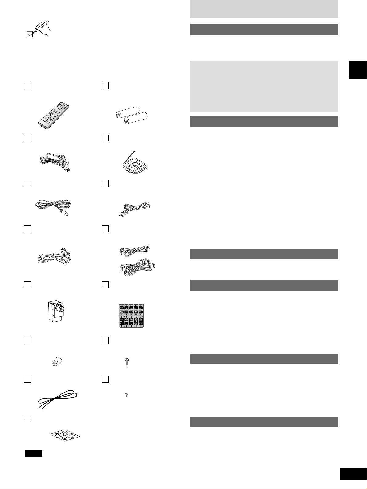
Accessories
Please check and identify the supplied accessories.
Use numbers indicated in parentheses when asking
for replacement parts.
(Only for U.S.A.)
To order accessories contact 1-800-332-5368 or the website
(http:// www.panasonic.com).
(Only for Canada)
To order accessories, call the dealer from whom you have
made your purchase.
Simple setup
STEP 1 Speaker assembly................................................7
STEP 2 Positioning
.............................................................8
STEP 3 Connection
..........................................................10
STEP 4 The remote control
............................................12
STEP 5 QUICK SETUP
.....................................................12
1 Remote control
(EUR7623X20)
2 Batteries
for remote control
1 AC power supply cord
(RJA0065-K)
1 AM loop antenna
(N1DAAAA00001)
1 FM indoor antenna
(RSA0007)
1 Video cable
(K2KA2HA00003)
1 System cable
(K1HA25JA0002)
5 Speaker cables
3 × 4 m (13 feet) (REE1203A)
2 × 10 m (33 feet) (REE1203C)
1 Antenna plug
(K2RC021B0001)
1 Sheet of speaker-cable
stickers
(RQCA1029)
4 Clips
(QWBG002AA)
8 Screws
(XSN5+16FN)
1 String for main unit
(RMF0321)
4 Black screws
(XTB3+10JFZ)
1 Sheet of speaker feet
(RFA1388A)
The included AC power supply cord is for use with this unit only.
Do not use it with other equipment.
Note

4
RQT6945
Getting started
IMPORTANT SAFETY INSTRUCTIONS
1) Read these instructions.
2) Keep these instructions.
3) Heed all warnings.
4) Follow all instructions.
5) Do not use this apparatus near water.
6) Clean only with dry cloth.
7) Do not block any ventilation openings. Install in accordance
with the manufacturer’s instructions.
8) Do not install near any heat sources such as radiators, heat
registers, stoves, or other apparatus (including amplifiers) that
produce heat.
9) Do not defeat the safety purpose of the polarized or
grounding-type plug. A polarized plug has two blades with one
wider than the other. A grounding-type plug has two blades
and a third grounding prong. The wide blade or the third prong
are provided for your safety. If the provided plug does not fit
into your outlet, consult an electrician for replacement of the
obsolete outlet.
10) Protect the power cord from being walked on or pinched
particularly at plugs, convenience receptacles, and the point
where they exit from the apparatus.
Read these operating instructions carefully before using the unit. Follow the safety instructions on the unit and the applicable safety instructions
listed below. Keep these operating instructions handy for future reference.
11) Only use attachments/accessories specified by the
manufacturer.
12) Use only with the cart, stand, tripod, bracket,
or table specified by the manufacturer, or sold
with the apparatus. When a cart is used, use
caution when moving the cart/apparatus
combination to avoid injury from tip-over.
13) Unplug this apparatus during lightning storms or when unused
for long periods of time.
14) Refer all servicing to qualified service personnel. Servicing is
required when the apparatus has been damaged in any way,
such as power-supply cord or plug is damaged, liquid has
been spilled or objects have fallen into the apparatus, the
apparatus has been exposed to rain or moisture, does not
operate normally, or has been dropped.
5
RQT6945
Getting started
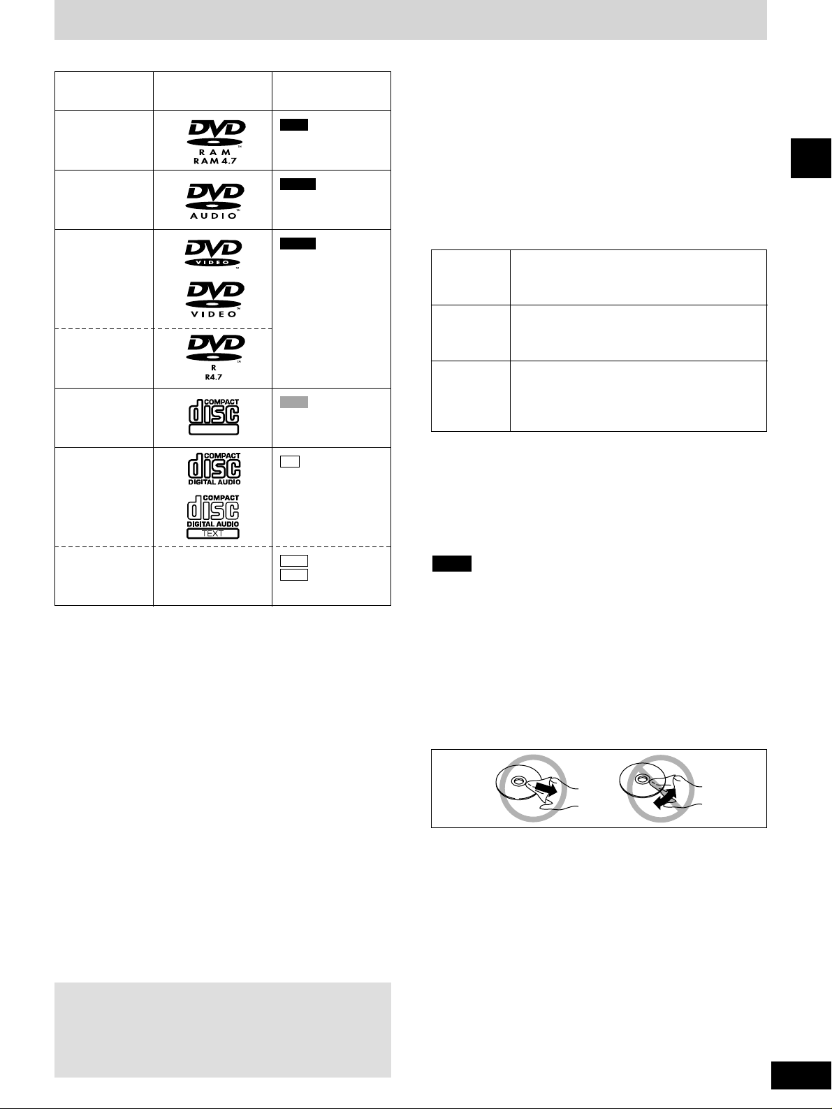
■ Discs that can be played
Disc type
DVD-RAM
DVD-Audio
DVD-Video
DVD-R
Video CD
CD
CD-R/RW
Logo
Indication used in
instructions
DIGITAL VIDEO
RAM
DVD-A
DVD-V
VCD
CD
WMA
MP3
Including CD text
¡Use discs with the above logos and that conform to specifications.
The unit cannot play other discs correctly.
¡Do not use irregularly shaped discs (e.g. heart-shaped), as these
can damage the unit.
■ Discs that cannot be played
PAL discs (except DVD-Audio), DVD-RAM (2.6 GB, TYPE 1),
DVD-ROM, CD-ROM, CDV, CD-G, +RW, DVD-RW, CVD, SVCD,
SACD, Divx Video Discs and Photo CD.
■ Disc structure
Disc structure and the labels given to the items on discs depend on
the disc type.
Track: the smallest division on DVD-Audio, CDs and Video
CDs, or a single WMA/MP3 file.
Chapter: the smallest division on DVD-Video.
Group: collections of tracks on DVD-Audio and equivalent to
folders or albums on data discs.
Title: the largest division on DVD-Video, usually an entire
movie.
Program: the division on DVD-RAM equivalent to a single
recording.
Play list: a group of scenes on DVD-RAM.
Scene: DVD-RAM program sections specified and grouped into
play lists on a DVD video recorder.
■ CD-R and CD-RW discs
This unit can play CD-R/RW (audio recording disc) recorded with
CD-DA, video CD, WMA or MP3. Finalize∗the disc after recording.
■ DVD-R discs
Panasonic DVD-R recorded and finalized∗on a Panasonic DVD
video recorder are played as DVD-Video on this unit.
∗
A process that allows play on compatible equipment.
■ DVD-RAM discs
DVD-RAM discs must meet the following conditions for this unit to
be able to play them.
Playing DVDs and Video CDs
The producer of these discs can control how they are played
so you may not always be able to control play as described in
these operating instructions (for example if the play time is not
displayed or if a Video CD has menus).
Read the disc’s instructions carefully.
Type
¡Non-cartridge discs
¡Discs that can be removed from their
cartridges (TYPE 2 and 4)
¡12 cm (5'') 9.4 GB (double-sided) and 4.7 GB
(single-sided)
¡8 cm (3'') 2.8 GB (double-sided)
Discs recorded with DVD video recorders, DVD
video cameras, personal computers, etc., using
Version 1.1 of the Video Recording Format (a
unified video recording standard).
¡Remove TYPE 2 and 4 discs from their cartridges before use,
then return them when you are finished. Read the instructions for
the disc carefully.
¡Do not allow the disc to become dirty or scratched. Store discs in
their cartridges and ensure the disc label and cartridge label face
the same way.
¡Some parts of the disc, for example where one program ends and
another begins, may not play smoothly.
It may not be possible to play CD-R, CD-RW, DVD-R and DVD-RAM
in all cases due to the type of disc or condition of the recording.
■ Playing PAL system DVD-Audio
This unit converts PAL to NTSC for play. The picture is compressed
to show it in its entirety, but this may cause it to be stretched
vertically.
■ To clean discs
DVD-Audio, DVD-Video, Video CD, CD
Wipe with a damp cloth and then wipe dry.
Note
Capacity
Recording
format
DVD-RAM, DVD-R
¡Clean with an optional DVD-RAM/PD disc cleaner (LF-K200DCA1,
where available).
¡Never use cloths or cleaners for CDs etc.
■ Handling precautions
¡Do not write on the label side with a ball-point pen or other writing
instrument.
¡Do not use record cleaning sprays, benzine, thinner, static
electricity prevention liquids or any other solvent.
¡Do not attach labels or stickers to discs. (Do not use discs with
exposed adhesive from tape or left over peeled-off stickers.)
¡Do not use scratch-proof protectors or covers.
¡Do not use discs printed with label printers available on the
market.
Disc information
–
6
RQT6945
Getting started
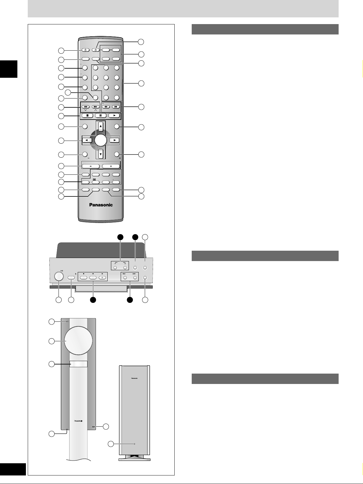
Control reference guide
q Standby/on switch [^]..............................................................12
w Sleep button [SLEEP] ..............................................................28
e FL display, Dimmer button [FL DISPLAY, –DIMMER] ....25, 28
r Play mode, Mix 2ch button
[PLAY MODE, –MIX 2CH] ..................................................16, 25
t Repeat button [REPEAT] ........................................................15
y Cancel button [CANCEL] ........................................................16
u Position memory button [POSITION MEMORY]....................14
i Skip, Preset channel, TV channel buttons
[uiSKIP, 2 CH 1] ..............................................14, 24, 32
o Basic operation buttons..........................................................13
!0 Top menu, Direct navigator button
[TOP MENU, DIRECT NAVIGATOR]..................................14, 20
!1 Cursor buttons [e, r, w, q], Enter button [ENTER] ............12
!2 Display, TV volume down button
[DISPLAY, TV VOL –] ........................................................21, 32
!3 Volume buttons [–, +, VOLUME] ............................................13
!4 Muting button [MUTING]..........................................................28
!5 Sound field, sound quality buttons..................................25–27
!6 FM mode, Setup button [FM MODE, SETUP] ..................12, 24
!7 Zoom button [ZOOM] ..............................................................18
!8 AV system standby/on button [^, AV SYSTEM]....................32
!9 Source select buttons
¡Face towards this unit to change the source.
¡Press [TV] or [VCR/AUX] first to operate a Panasonic
television or video cassette recorder (\ page 32).
@0 TV/VIDEO button [TV/VIDEO]..................................................32
@1 Numbered buttons [1–9, 0,
>
=
10/ENTER] ................................14
@2 Slow/search, Tuning buttons
[t, y SLOW/SEARCH] ................................................14, 24
@3 Menu, Play list button [MENU, PLAY LIST]......................14, 20
@4 Return, TV volume up button [RETURN, TV VOL +] ......12, 32
@5 Audio button [AUDIO]..............................................................17
@6 Group button [GROUP]............................................................15
Buttons i, o, !3 and !5 function the same as the controls on
the remote control.
@7 Standby/on switch [POWER 8] ............................................13
Press to switch the unit from on to standby mode or vice versa.
In standby mode, the unit is still consuming a small amount of
power.
@8 Open/close button [OPEN/CLOSE ;] ....................................13
@9 Progressive out button [PROGRESSIVE OUT]......................13
#0 Source select button [SELECTOR] ........................................13
#1 Standby/on indicator [^]
When the unit is connected to the AC mains supply, this indicator
lights up in standby mode and goes out when the unit is turned
on.
#2 Loading tray..............................................................................13
#3 Display
#4 Headphone jack [PHONES] ....................................................28
#5 Remote control signal sensor
Remote control
Main unit
#6 AC supply indicator [AC IN]
This indicator lights when the unit is connected to the AC mains
supply.
Subwoofer
AV SYSTEM
SLEEP
FL DISPLAY
DIMMER
PLAY MODE
MIX 2CH
REPEAT
CANCEL
SKIP
CH
TOP MENU
DISPLAY
VOLUME
MUTING
PL C.FOCUS
SFC
SUBWOOFER
LEVEL
FM MODE
SETUP
ZOOM GROUP AUDIO
RETURN
TV VOL TV VOL
DIRECT
NAVIGATOR
PLAY LIST
MENU
SLOW/SEARCH
123
456
7809
TUNER/BAND DVD/CD
TV VCR/AUX
ENTER
CH SELECT
TEST
TV/VIDEO
POSITION
MEMORY
S.SRND
C.S.M
SELECTOR
PROGRESSIVE
OUT
OPEN/CLOSE
POWER
CUSTOM SOUND
MEMORY
VOLUME
2
1
PHONES
1
18
19
20
21
22
23
24
25
26
2
3
4
5
6
7
8
9
10
11
12
13
14
15
16
17
2915
2827
31
32
33
34
35
36
309 8
13
10/
ENTER
>
=
AC IN
Top of main unit
Main unit
Subwoofer
Simple setup
7
RQT6945
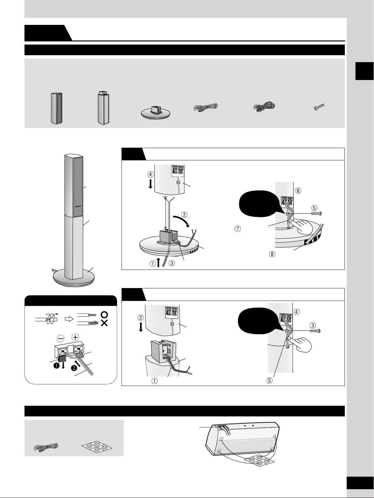
Speaker assembly
Preparing the center speaker
Preparing the front and surround speakers
4 Speaker units 4 Stands 4 Bases 2 Short cables
(for FRONT L/R)
2 Long cables
(for SURROUND L/R)
8 Screws
Speaker
unit
Stand
Base
Speaker unit
Stand/Base
Place into
groove.
Position wire in grooves as
necessary avoiding knots.
Confirm screw is
securely fastened.
Confirm screw is
securely fastened.
Place into groove.
Connect the
speaker cables.
Fit into groove.
Connect the
speaker cables.
(
\\
above)
1 Short cable
(for CENTER)
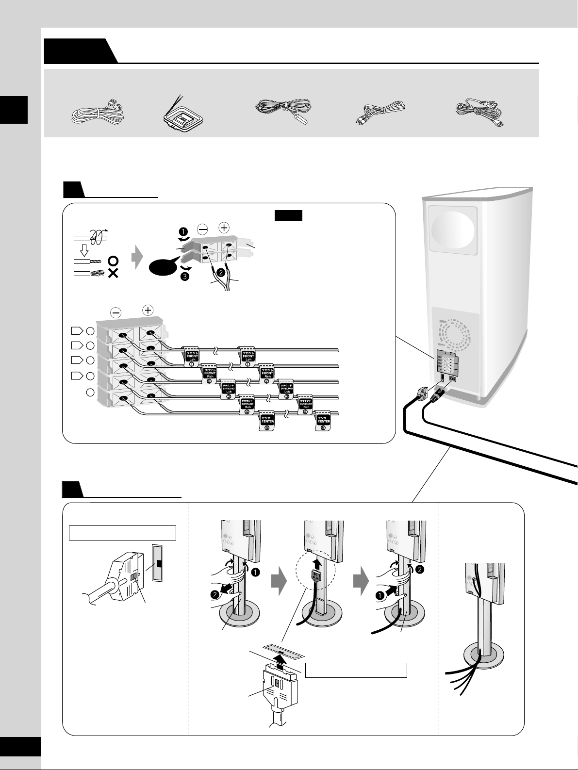
Connecting the cables
The speaker units, stands, and bases for the front and surround speakers are the same.
Only the lengths of the cables are different.
Black
Red
Copper
Silver
1 Sheet of speaker
feet (4 feet per sheet)
¡You can put front and surround speakers on the shelf by connecting a speaker directly to the base.
Simple setup
STEP 1
\
\
Stand + Base
1
Speaker unit + Stand/Base
2
Stand
Approx.
120 mm
(4-3/4")
Fit into groove.
Base
Connect the
speaker cables.
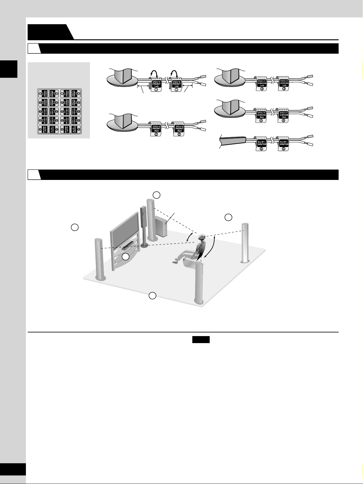
Simple setup
1 Sheet of
speaker-cable
stickers
Front (L)
Front (R)
Surround (L)
Surround (R)
Center
short cable
short cable
long cable
long cable
short cable
Front (L)
Front (R)
Surround (L)
Surround (R)
Center
Setup example
Use only supplied speakers
Using other speakers can damage the unit and sound quality will be
negatively affected.
¡Set the speakers up on an even surface to prevent them from
falling. Take proper precautions to prevent the speakers from
falling if you cannot set them up on an even surface.
¡The speaker nets cannot be removed.
Positioning for best effect
How you set up your speakers can affect the bass and the sound
field. Note the following points.
¡Place speakers on flat secure bases.
¡Placing speakers too close to floors, walls, and corners can result
in excessive bass. Cover walls and windows with thick curtain.
Keep your speakers at least 10 mm (13/32") away from the system
for proper ventilation.
Center speaker
Vibration caused by the center speaker can disrupt the picture if it is
placed directly on the television. Put the center speaker on a rack or
shelf.
Subwoofer
Place to the right of the television, on the floor or a sturdy shelf so
that it won’t cause vibration.
Leave 10 cm (4") on the right for the woofer to be effective.
Leave 10 cm (4") at the rear for ventilation.
Note
Main unit
Subwoofer
Approx. 50 mm (2") Approx. 50 mm (2")
8
RQT6945
Attach the stickers to the cables
Position the speakers
Simple setup
Positioning
STEP 2
¡The front and surround speakers are
the same. Use those you have
connected the short cords to as front
speakers and those you have
connected the long cords to as
surround speakers.
¡Place the front, center, and surround
speakers at approximately the same
distance from the seating position. The
angles in the diagram are approximate.
1
2
1
2
60
°
4
5
3
120°
9
RQT6945
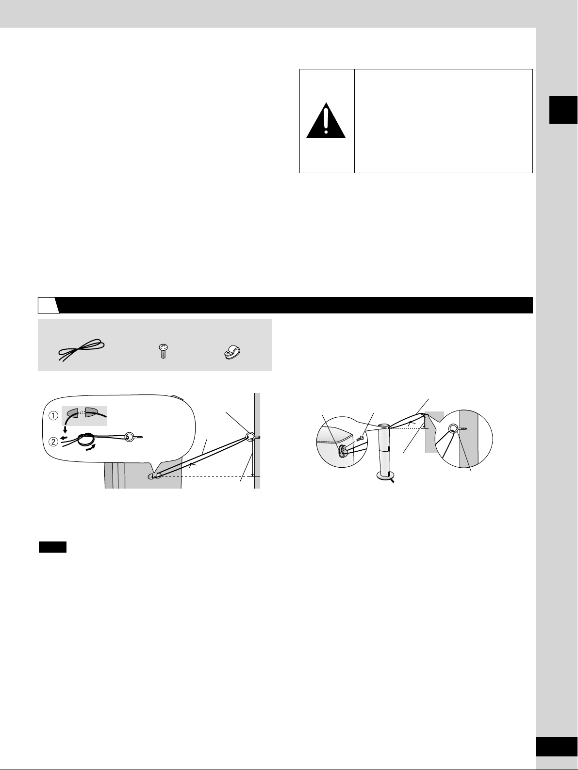
1 String for main unit 4 Black screws
4 Clips
■ Main unit ■ Front and surround speakers
Screw
(not included)
Approx. 150 mm
(5-15/16")
String for
main unit
Clip
Black screw
String
(not included)
Screw (not included)
Approx.
150 mm
(5-15/16")
Notes on speaker use
¡You can damage your speakers and shorten their useful life if you
play sound at high levels over extended periods.
¡Reduce the volume in the following cases to avoid damage.
— When playing distorted sound.
— When the speakers are receiving howling from a record player,
noise from FM broadcasts, or continuous signals from an
oscillator, test disc, or electronic instrument.
— When adjusting the sound quality.
— When turning the unit on or off.
If irregular coloring occurs on your television
These speakers are designed to be used close to a television, but
the picture may be affected with some televisions and set-up
combinations.
If this occurs, turn the television off for about 30 minutes.
The television’s demagnetizing function should correct the problem.
If it persists, move the speakers further away from the television.
Caution
¡¡
Use the speakers only with the
recommended system. Failure to do so
may lead to damage to the amplifier and/or
the speakers, and may result in the risk of
fire. Consult a qualified service person if
damage has occurred or if you experience
a sudden change in performance.
¡¡
Do not attach these speakers to walls or
ceilings.
To prevent the speakers and main unit from falling over
Simple setup
3
¡Use screws that are suitable for the type of walls and beams to
which you are attaching. (not included)
¡Use wall screws and string to prevent speakers from falling.
(not included)
Consult with a qualified professional housing contractor when attaching to a surface that may not have enough strength to support
the speakers or when attaching to a concrete wall. Not attaching properly may result in damage or injury from falling speakers or
other objects.
Note
Thread
the string through.
Thread through the ring
screw and tie firmly.
Simple setup
_
SPEA
KER
S
H
AU
T-PA
RLE
U
RS
F
R
O
N
T
(6Ω)
S
U
R
R
O
U
N
D
(6Ω)
C
E
N
T
E
R
(6Ω)
+
1
2
3
4
5
L
L
R
R
L
1
R
2
L
3
R
4
5
Click!
1 FM indoor antenna1 AM loop antenna1 System Cable 1 Video cable 1 AC power supply cord
Subwoofer
Main unit
Catch
Catch facing right
Catch facing out
Catch
To disconnect
Press the catch
and pull out.
To disconnect
Press the catch
and pull out.
Remove the cover
Fit the cover
You can also pass
other cables through
the removable cavity.
Subwoofer
¡Never short-circuit positive (+)
and negative (–) speaker wires.
¡Be sure to connect only positive
(copper) wires to positive (+)
terminals and negative (silver)
wires to negative (–) terminals.
Incorrect connection can
damage the speakers.
Note
Front (L)
Front (R)
Surround (L)
Surround (R)
Center
Black
Red
Copper
Silver
10
RQT6945
Simple setup
Connection
STEP 3
Speakers
1
System cable
2
TO SUBW
OOFER
Å
h
TO SUBW
OOFER
Å
h
TO SUBWOOFER
Å
h
TO SUBWOOFER
Å
h
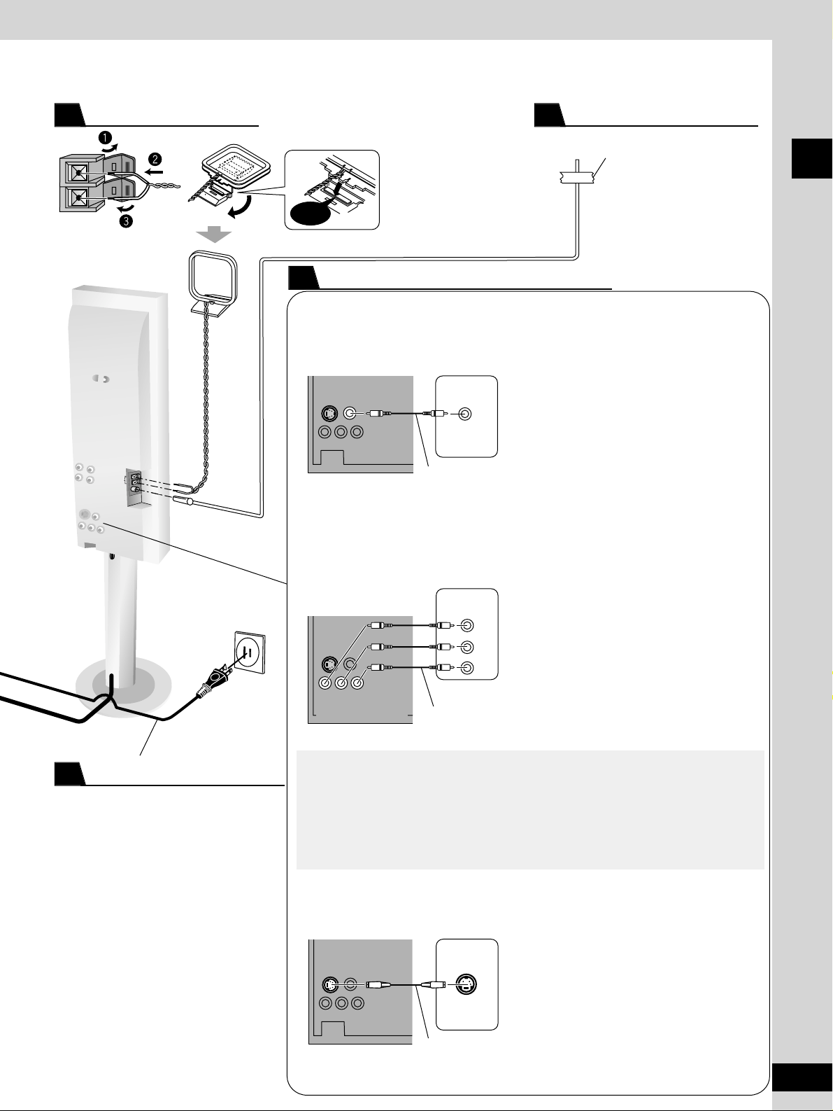
Click!
Television
VIDEO IN
COMPONENT
VIDEO IN
S VIDEO IN
COMPONENT VIDEO OUT
PB
PR
Y
TO SUBWOOFER
Å
h
AM ANT
FM ANT
EXT
LOOP
75Ω
Main unit
Adhesive tape
Place the antenna
where reception is
best.
Stand the antenna up on
its base.
Keep loose antenna cord
away from other wires
and cords.
■ Connecting a television using the VIDEO IN terminal
■ Connecting a television using the COMPONENT
VIDEO IN terminals
■ Connecting a television using the S VIDEO IN terminal
Connect directly to your television.
Do not connect the unit through a video cassette
recorder, because the picture may not be played
correctly due to the copy guard.
COMPONENT VIDEO OUT terminals
These terminals can be used for either interlace or
progressive output and provide a purer picture
than the S VIDEO OUT terminal. Connection using
these terminals outputs the color difference signals
(PB/PR) and luminance signal (Y) separately in
order to achieve high fidelity in reproducing colors.
¡The description of the component video input
terminals depends on the television or monitor
(e.g. Y/PB/PR, Y/B-Y/R-Y, Y/CB/CR).
Connect to terminals of the same color.
¡After making this connection, change the black
level for a better picture (\ page 29, Video—
Black Level Control).
To enjoy progressive video
¡Connect to the component video (480P) input terminals on a television compatible with
this unit’s copy guard system. (Video will not be displayed correctly if connected to an
incompatible television.)
¡Press [PROGRESSIVE OUT] on the main unit so “PROGRESSIVE” appears on the
display (\ page 13).
¡All televisions manufactured by Panasonic and that have 480P input connectors are
compatible. Consult the manufacturer if you have another brand of television.
S VIDEO OUT terminal
The S VIDEO OUT terminal achieves a more vivid
picture than the VIDEO OUT terminal by separating
the chrominance (C) and luminance (Y) signals.
(Actual results depend on the television.)
Video cable
Video cables
(not included)
S video cable
(not included)
Connect the AC power supply cord after
all other connections are complete.
Conserving power
The unit consumes power (approx. 0.5 W)
even when it is turned off with [POWER 8].
To save power when the unit is not to be
used for a long time, unplug it from the
household AC outlet.
Remember to reset the radio stations and
any other memory items before using the
unit again.
Information you enter into the unit’s
memory remains intact for up to 2 weeks
after the AC power supply cord is
disconnected.
11
RQT6945
Simple setup
AM loop antenna
3
FM indoor antenna
4
Connection to your television
5
AC power supply cord
6
To household AC outlet
(AC 120 V, 60 Hz)
VIDEO
OUT
Y
PB PR
S VIDEO
OUT
12
RQT6945
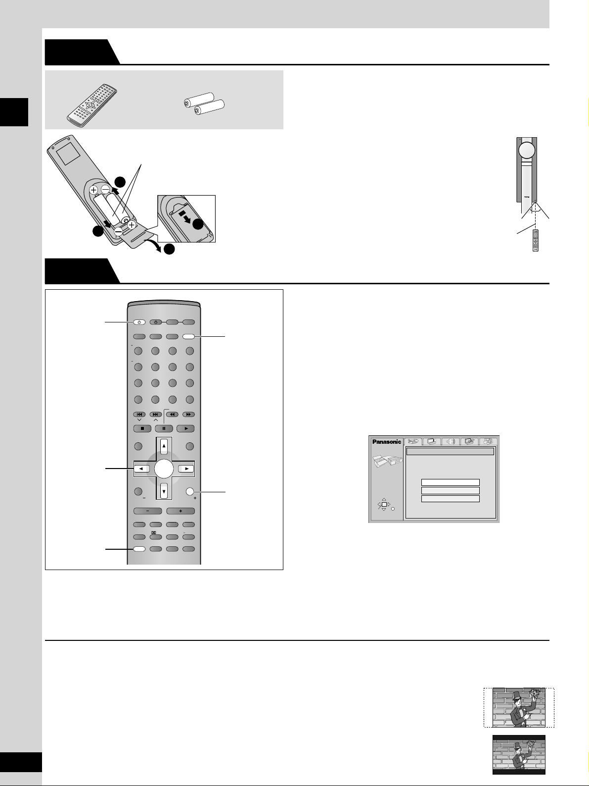
Simple setup
1 Remote control 2 Batteries
Do not;
¡mix old and new batteries.
¡use different types at the same time.
¡heat or expose to flame.
¡take apart or short circuit.
¡attempt to recharge alkaline or manganese batteries.
¡use batteries if the covering has been peeled off.
Mishandling of batteries can cause electrolyte
leakage which can damage items the fluid contacts
and may cause a fire.
Remove if the remote control is not going to be
used for a long period of time. Store in a cool, dark
place.
■ Use
Aim at the sensor, avoiding obstacles, at a
maximum range of 7 m (23 feet) directly in front of
the unit.
2
3
3
1
¡Insert so the poles (+ and –)
match those in the remote
control.
¡Do not use rechargeable type
batteries.
R6/LR6,
AA, UM-3
The QUICK SETUP screen appears when you press [SETUP] the
first time after purchase and assists you to make necessary
settings. You can access this screen again later if you need to
(\ page 29, Others—QUICK SETUP).
Preparation
Turn on the television and select the appropriate video input on the
television to suit the connections for the unit.
1 Press [^] to turn on the unit.
2 Press [DVD/CD] to select “DVD/CD”
as the source.
3 Press [SETUP] to show the QUICK
SETUP screen.
4 Press [e, r] to select the menu
language and press [ENTER].
5 Press [e, r] to select “Yes” to
continue and press [ENTER].
6 Press [e, r] to select the item and
press [ENTER].
¡¡
Audio Language (\ page 29)
¡¡
TV Type (\ below)
¡¡
Subtitle Language (\ page 29)¡¡TV Aspect (\ below)
7 Press [ENTER] and then [SETUP] to
end the settings.
To return to the previous screen
Press [RETURN].
■ TV Type
Select to suit the type of television.
¡¡
Standard (Direct View TV) (factory preset)
¡¡
CRT Projector
¡¡
LCD TV/Projector
¡¡
Projection TV
¡¡
Plasma TV
■ TV Aspect
Select “4:3” (regular) or “16:9” (widescreen) to suit your television.
If you have a regular 4:3 television, you can also select how video
on some discs is shown (
\ page 29, Video–TV Aspect).
¡4:3 Pan&Scan (factory preset)
Widescreen software is expanded to fill the
screen of a 4:3 aspect television (unless
prohibited by the producer of the disc).
¡4:3 Letterbox
Widescreen software is shown in the
letterbox style on a 4:3 aspect television.
SELECT
SETUP
QUICK SETUP
Select the menu language.
ENTER RETURN
English
Français
Español
Simple setup
The remote control
STEP 4
QUICK SETUP
STEP 5
30°
7 m
(23 feet)
30°
AV SYSTEM
SLEEP
FL DISPLAY
DIMMER
PLAY MODE
MIX 2CH
REPEAT
CANCEL
SKIP
CH
TOP MENU
DISPLAY
VOLUME
MUTING
PL C.FOCUS
SFC
SUBWOOFER
LEVEL
FM MODE
SETUP
ZOOM GROUP AUDIO
RETURN
TV VOL – TV VOL +
DIRECT
NAVIGATOR
PLAY LIST
MENU
SLOW/SEARCH
123
456
7809
TUNER/BANDDVD/CD
TV VCR/AUX
ENTER
CH SELECT
TEST
TV/VIDEO
>
=
10/
ENTER
POSITION
MEMORY
S.SRND
C.S.M
AV SYSTEM
TV VCR/AUX
1
4–7
SLEEP
TUNER/BAND DVD/CD
TV/VIDEO
FL DISPLAY
DIMMER
123
PLAY MODE
MIX 2CH
456
REPEAT
7809
POSITION
CANCEL
MEMORY
SKIP
CH
TOP MENU
DIRECT
NAVIGATOR
DISPLAY
TV VOL TV VOL
MUTING
S.SRND
FM MODE
SETUP
>
10/
=
SLOW/SEARCH
PLAY LIST
ENTER
RETURN
VOLUME
SUBWOOFER
C.S.M
ZOOM GROUP AUDIO
SFC
PL C.FOCUS
LEVEL
CH SELECT
ENTER
MENU
TEST
3, 7
2
RETURN
PHONES
r
 Loading...