


 Loading...
Quick Installation Guide
2.4 GHz Cell Station Unit
Model No. KX-T0141
KX-TDA0142
KX-T0151
KX-TDA0152
Thank you for purchasing a Panasonic 2.4 GHz Cell Station Unit.
Please read this manual carefully before using this product and save this manual for future use.
Document Version: 2009-12

Important Information
Important Information
SAVE THESE INSTRUCTIONS
Safety Notices
Please observe the safety notices in this manual in order to avoid danger to users or other people, and prevent damage to property.
The notices are classified as follows, according to the severity of injury or damage:
WARNING |
This notice means that misuse could result in death or serious injury. |
|
|
CAUTION |
This notice means that misuse could result in injury or damage to |
|
property. |
|
|
WARNING |
|
SAFETY REQUIREMENTS |
|
•The product must only be installed and serviced by qualified service personnel. The product should be used as-is from the time of purchase; it should not be disassembled or modified. Disassembly or modification can cause a fire, electric shock, or damage to the product.
•Make sure that the wall that the unit will be attached to is strong enough to support the unit (approx. 310 g [11 oz]). If not, it is necessary for the wall to be reinforced.
•Only use the wall-mounting equipment (screws, washers, wall mounting plate) included with the unit.
•When this product is no longer in use, make sure to detach it from the wall.
•Do not connect or disconnect the telephone cord with wet hands.
•Disconnect the unit from the telephone cord, and contact the dealer if:
–The unit is exposed to rain, water, or any other liquid.
–The unit is dropped or damaged.
–Internal components are exposed due to damage.
–The unit does not operate properly.
–Performance deteriorates.
•Disconnect the unit from the telephone cord if the unit emits smoke, an abnormal smell, or makes unusual noise. These conditions can cause fire or electric shock. Confirm that smoke has stopped and contact an authorized service center.
•Do not touch the unit, or telephone cord during a lightning storm.
•Do not allow anything to rest on the telephone cord. Do not locate this unit where the telephone cord may be stepped on or tripped on.
CAUTION
SAFETY REQUIREMENTS
•The CS should be kept free of dust, moisture, high temperature (more than 40 °C [104 °F]), low temperature (less than 0 °C [32 °F]), and vibration, and should not be exposed to direct sunlight.
•The CS should not be placed outdoors (use indoors).
•The CS should not be placed near high-voltage equipment.
•The CS should not be placed on a metal object.
•Systems using 2.4 GHz ISM (Industrial, Scientific and Medical) band may interfere with the Panasonic wireless system. Examples of such systems are cordless telephones, wireless LAN, Home RF, microwave ovens and other ISM devices. These systems may cause minor noise.
2 |
Quick Installation Guide |
Document Version 2009-12 |
|
|
|

Important Information
•When driving the screws into the wall, be careful to avoid touching any metal laths, wire laths or metal plates in the wall.
•To prevent malfunction, deformity, overheating, rust, and discoloration, do not install or place equipment in the following types of locations:
–Locations where air ventilation is poor.
–Locations that may be exposed to sulphurous gas, such as near hot springs.
–Near devices that emit heat, such as heaters.
–Near devices that emit electromagnetic noise, such as radios or televisions.
–Near devices that emit high-frequency noise, such as sewing machines or welders.
•Do not stretch or bend the cables. Also, do not allow anything to rest on the cables.
•Use cables that are fire-resistant or fireproof.
•The CS and the cables should never be placed near or over a radiator or other heat source.
•Do not bundle cables that are connected to the CS with the AC power cords of machines located nearby.
•Make sure the cables are securely fastened to the wall.
•Disconnect the telephone cord from the unit before cleaning. Clean the unit with a soft, dry cloth. Do not use liquid, aerosol cleaners, abrasive powders, or chemical agents to clean the unit.
•When left unused for a long period of time, disconnect the unit from the telephone cord.
•Medical—consult the manufacturer of any personal medical devices, such as pacemakers, to determine if they are adequately shielded from external RF (radio frequency) energy. (The unit operates in the frequency range of 2400 MHz to 2483 MHz, and the output peak power level is less than
0.25 W.) Do not use the unit in health care facilities if any regulations posted in the area instruct you not to do so. Hospitals or health care facilities may be using equipment that could be sensitive to external RF (radio frequency) energy.
Notice
SAFETY REQUIREMENTS
•Before connecting the unit, confirm that the unit supports the intended operating environment.
•If the unit does not operate properly, disconnect the telephone cord, then connect again.
•The unit may not operate in the event of a power failure.
•Do not move the unit while it is in use.
•Satisfactory operation, interoperability, and compatibility cannot be guaranteed with all equipment connected to the unit, nor with all services provided by telecommunications providers over networks connected to the unit.
SECURITY REQUIREMENTS
•Privacy of communications may not be ensured when using the wireless systems.
Document Version 2009-12 |
Quick Installation Guide |
3 |
|
|
|

Important Information
Additional Information
F.C.C. REQUIREMENTS AND RELEVANT INFORMATION
CAUTION
Any changes or modifications not expressly approved by the party responsible for compliance could void the user's authority to operate this device.
Note
This equipment has been tested and found to comply with the limits for a Class B digital device, pursuant to Part 15 of the FCC Rules. These limits are designed to provide reasonable protection against harmful interference in a residential installation. This equipment generates, uses, and can radiate radio frequency energy and, if not installed and used in accordance with the instructions, may cause harmful interference to radio communications. However, there is no guarantee that interference will not occur in a particular installation. If this equipment does cause harmful interference to radio or television reception, which can be determined by turning the equipment off and on, the user is encouraged to try to correct the interference by one or more of the following measures:
•Reorient or relocate the receiving antenna.
•Increase the distance between the equipment and receiver.
•Connect the equipment to an outlet on a circuit different from that to which the receiver is connected.
•Consult the dealer or an experienced radio/TV technician for help.
Some wireless telephones operate at frequencies that may cause interference to nearby TVs and VCRs. To minimize or prevent such interference, the base of the wireless telephone should not be placed near or on top of a TV or VCR. If interference is experienced, move the wireless telephone further away from the TV or VCR. This will often reduce, or eliminate, interference.
RF Exposure Warning:
This product complies with FCC radiation exposure limits set forth for an uncontrolled environment. To comply with FCC RF exposure requirements, this product must be installed and operated in accordance with the provided instructions. The installed unit requires a minimum 20 cm (8 inches) of spacing between the antenna and a person's body (excluding hands, wrists and feet) during wireless modes of operation.
This transmitter must not be co-located or operated in conjunction with any other antennas or transmitters.
4 |
Quick Installation Guide |
Document Version 2009-12 |
|
|
|

|
|
Table of Contents |
Table of Contents |
|
|
1 |
Overview ................................................................................................... |
6 |
2 |
Procedure Overview ................................................................................ |
9 |
3 |
Site Planning .......................................................................................... |
11 |
4 |
Before Site Survey ................................................................................. |
15 |
5 |
Site Survey .............................................................................................. |
19 |
6 |
After Site Survey .................................................................................... |
23 |
7 |
Connecting a Cell Station to the PBX .................................................. |
24 |
8 |
Wall Mounting ......................................................................................... |
34 |
9 |
Troubleshooting ..................................................................................... |
39 |
Document Version 2009-12 |
Quick Installation Guide |
5 |
|
|
|
1Overview
1Overview
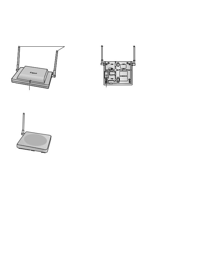
Names and Locations
KX-T0151/KX-TDA0152
Antennas


 RJ11 Modular
DIP Switch
LED
KX-T0141/KX-TDA0142
Antennas
|
|
RJ11 Modular |
|
|
DIP Switch |
LED Indications (KX-T0151/KX-TDA0152) |
||
Indication |
Color |
Description |
STATUS |
Green/Red |
CS status indication |
|
|
• OFF: Power Off |
|
|
• Green ON: Stand-by (no active calls) |
|
|
• Slow Green Flashing (60 times per minute): Talk (active calls) |
|
|
• Moderate Green Flashing (120 times per minute): Busy |
|
|
• Red ON: Fault (includes Initialization) |
|
|
• Red Flashing (60 times per minute): Out of Service/Starting up |
|
|
CS status indication during the site survey |
|
|
• Red ON: The CS is connected to an AC adaptor/battery box. |
|
|
• Red Flashing (60 times per minute): The CS is connected to the |
|
|
PBX. |
6 |
Quick Installation Guide |
Document Version 2009-12 |
|
|
|

1 Overview
Maximum Number of Calls
Cell Stations (CSs) determine the area covered by the wireless system. The number of calls that can be made simultaneously through each CS varies depending on the model, as follows:
Cell Station |
|
Maximum Calls |
|
Compatible Portable Station |
|
|
|
|
|
KX-T0151 |
2 |
|
• |
KX-TD7684 |
|
|
|
• |
KX-TD7694 |
KX-TDA0152 |
3 |
|
||
|
• |
KX-TD7680 |
||
|
|
|
||
KX-T0141 |
2 |
|
||
|
• |
KX-TD7690 |
||
KX-TDA0142 |
3 |
|
|
|
|
|
|
|
|
Note
For more details about the Portable Station (PS), refer to the Operating Instructions of the PS.
Maximum Number of CSs Supported by PBX
Notice
The CSs are for connection to specified Panasonic PBXs only.
The following number of CSs can be supported by each PBX.
PBX |
|
Connected via |
|
Maximum Number |
|
||
|
|
|
|
|
|||
|
KX-T0151 |
KX-TDA0152 |
KX-T0141 |
KX-TDA0142 |
|||
|
|
|
|||||
|
|
|
|
|
|
|
|
KX-TAW848 |
• |
Hybrid Ports |
4 |
- |
4 |
- |
|
• |
HLC card |
||||||
|
|
|
|
|
|||
|
|
|
|
|
|
|
|
KX-TDA50 |
• |
Super Hybrid |
|
|
|
|
|
|
Ports |
|
|
|
|
||
(with Additional AC |
• |
8 |
- |
8 |
- |
||
HLC card |
|||||||
Adaptor) |
|
|
|
|
|||
• |
DLC card |
|
|
|
|
||
|
|
|
|
|
|||
|
|
|
|
|
|
|
|
KX-TDA100/ |
• |
DHLC card |
32 |
- |
32 |
- |
|
• |
DLC card |
||||||
|
|
|
|
||||
KX-TDA200 |
|
|
|
|
|
|
|
• |
CSIF card |
- |
32 |
- |
32 |
||
|
|||||||
|
|
|
|
|
|
|
|
|
• |
DHLC card |
128 |
- |
128 |
- |
|
KX-TDA600 |
• |
DLC card |
|||||
|
|
|
|
||||
|
• |
CSIF card |
- |
128 |
- |
128 |
|
|
|
|
|
|
|
|
|
KX-TDE100/ |
• |
DHLC card |
32 |
- |
32 |
- |
|
• |
DLC card |
||||||
|
|
|
|
||||
KX-TDE200 |
|
|
|
|
|
|
|
• |
CSIF card |
- |
32 |
- |
32 |
||
|
|||||||
|
|
|
|
|
|
|
|
|
• |
DHLC card |
128 |
- |
128 |
- |
|
KX-TDE600 |
• |
DLC card |
|||||
|
|
|
|
||||
|
• |
CSIF card |
- |
128 |
- |
128 |
|
|
|
|
|
|
|
|
|
KX-NCP500 |
• |
DHLC card |
4 |
- |
4 |
- |
|
• |
DLC card |
||||||
|
|
|
|
|
|||
|
|
|
|
|
|
|
|
Document Version 2009-12 |
Quick Installation Guide |
7 |
|
|
|

1 Overview
PBX |
|
Connected via |
|
Maximum Number |
|
||
|
|
|
|
|
|||
|
KX-T0151 |
KX-TDA0152 |
KX-T0141 |
KX-TDA0142 |
|||
|
|
|
|||||
|
|
|
|
|
|
|
|
KX-NCP1000 |
• |
DHLC card |
8 |
- |
8 |
- |
|
• |
DLC card |
||||||
|
|
|
|
|
|||
|
|
|
|
|
|
|
|
Required Distances between Equipment
CAUTION
Maintain the distances listed below between equipment in order to prevent noise, interference or the disconnection of a conversation. (The distance may vary depending on the environment.)
Equipment |
Distance |
|
|
CS and office equipment such as a computer, telex, fax |
More than 2 m (6 ft 7 in) |
machine, etc., or microwaves |
|
|
|
CS and PS |
More than 1 m (3 ft 3 in) |
|
|
Each CS |
More than 15 m (49 ft) |
|
|
Each PS |
More than 0.5 m (1 ft 8 in) |
|
|
PBX and CS |
More than 2 m (6 ft 7 in) |
|
|
Notice
The required distance between CSs may vary depending on the environment of the installation site and conditions in which the wireless system is used. Conduct a site survey to determine the appropriate distance.
RF Specification
Item |
Description |
|
|
Frequency Band |
2400 MHz to 2483 MHz |
|
|
Transmission Output |
Peak 0.25 W |
|
|
CAUTION
•The CS should be kept free of dust, moisture, high temperature (more than 40 °C [104 °F]), low temperature (less than 0 °C [32 °F]), and vibration, and should not be exposed to direct sunlight.
•The CS should not be placed outdoors (use indoors).
•The CS should not be placed near high-voltage equipment.
•The CS should not be placed on a metal object.
•Systems using 2.4 GHz ISM (Industrial, Scientific and Medical) band may interfere with the Panasonic wireless system. Examples of such systems are cordless telephones, wireless LAN, Home RF, microwave ovens and other ISM devices. These systems may cause minor noise.
Notice
Please take into consideration the distance between the CSs when site planning. Please consult a certified dealer for details.
8 |
Quick Installation Guide |
Document Version 2009-12 |
|
|
|

2 Procedure Overview
2 Procedure Overview
When connecting the wireless system, use extreme care in conducting the site survey. An incorrectly performed site survey can result in poor service area, frequent noise, and disconnection of calls.
1. Investigate the installation site
Refer to "3 Site Planning".
a.Obtain a map of the CS installation site.
b.Identify the service area required by the user on the map.
c.Plan the location of each CS, taking account of distance, building materials, etc.
2.Prepare for site survey
Refer to "4 Before Site Survey".
a.Assign a CS number to each CS by setting the DIP switches on the back of the CS.
b.Supply electricity to each CS using an AC adaptor/battery box or by connecting them to the PBX.
c.Install each CS temporarily as planned.
Note
•Install at least 2 m (6 ft 7 in) above the floor.
•Place the antennas so that they are pointing in directions that are 90 degrees apart (for antenna diversity).
3.Conduct the site survey
Refer to "5 Site Survey".
a.Test the radio signal strength using the PS.
Confirm that the radio signal strength level is "12" near the CS.
Using the KX-TD7684/KX-TD7694
1 |
9 |
0 |
Press 1, 9, and POWER for more than 2 seconds.
Using the KX-TD7680
Display example:
CS No. |
|
|
|
CS NO.1 LEVEL:12 |
1 to 9 |
<< SEARCHING >> |
|
|
SAVE:0123456789 |
|
|
|
||
|
|
|
|
|
|
|
|
|
1 |
9 |
Press 1, 9, and POWER for more than 2 seconds.

 0
0
Display example:
CS No. |
|
|
|
|
CS NO.1 LEVEL:12 |
|
|
<< SEARCHING >> |
|
|
SAVE:0123456789 |
|
|
|
|||
1 to 9 |
|
|
|
||
|
|
|
|
||
|
|
|
|
||
Document Version 2009-12 |
Quick Installation Guide |
9 |
|
|
|

2 Procedure Overview
Using the KX-TD7690
1 |
9 |
Press 1, 9, and POWER for more than 2 seconds.
Display example:
CS No. |
|
|
|
|
CS NO.1 LEVEL:12 |
|
|
<< SEARCHING >> |
|
|
SAVE:0123456789 |
|
|
|
|||
1 to 9 |
|
|
|
||
|
|
|
|
||
|
|
|
|
||
b.By walking away from the CS with the PS, check the radio signal strength. The radio signal strength weakens as you walk away from the CS.
c.Map the CS coverage area at radio signal strength levels "3" and "8".
d.Make sure that adjacent CS coverage areas overlap where the radio signal strength level is "8" by at least 5 m (16 ft).
e.Make sure that the radio signal strength level is greater than "3" at any location within the service area required by the user.
4. Finish the site survey
Refer to "6 After Site Survey".
a.Turn off the PS.
b.Stop supplying power, and return all DIP switches of each CS to the OFF position.
5. Connect the CS and PS to the PBX and test the operation
Refer to "7 Connecting a Cell Station to the PBX".
a.Connect the CSs to the PBX.
b.Register the PSs to the PBX.
c.Walk around the service area while having a conversation using a registered PS. If noise is frequent or conversations disconnect, relocate the CSs or install an additional CS.
6. Mount the CS on the wall
Refer to "8 Wall Mounting".
a. If there are no problems in testing, mount the CS on the wall.
10 |
Quick Installation Guide |
Document Version 2009-12 |
|
|
|

3 Site Planning
3 Site Planning
Choosing the best site for the CS requires careful planning and testing of essential areas. The best location may not always be convenient for installation. Read the following information before installing the unit.
Understanding Radio Waves
Characteristics of Radio Waves
The transmission of radio waves and the CS coverage area depend on the structure and materials of the building.
Office equipment, such as computers and fax machines, can interfere with radio waves. Such equipment may create noise or interfere with the performance of the PS.
The illustration below shows the special transmitting patterns of radio waves.
1.Radio waves are reflected by objects made of materials such as metal.
2.Radio waves are diffracted by objects such as metallic columns.
3.Radio waves penetrate objects made of materials such as glass.
1. Reflection
CS
Column
2. Diffraction
3. Penetration
Relationships between Radio Waves and Building Structure and Materials
•The CS coverage area is affected more by the building materials and their thickness than the number of obstacles.
•Radio waves tend to be reflected or diffracted by conductive objects and rarely penetrate them.
•Radio waves tend to penetrate insulated objects and are rarely reflected by them.
•Radio waves penetrate thin objects more than thick objects.
•The table below shows the transmission tendency of radio waves when they reach objects made from various materials.
Document Version 2009-12 |
Quick Installation Guide |
11 |
|
|
|

3 Site Planning
Object |
Material |
Transmission Tendency |
|
|
|
Wall |
Concrete |
The thicker they are, the less radio waves penetrate |
|
|
them. |
|
|
|
|
Ferroconcrete |
Radio waves can penetrate them, but the more iron |
|
|
there is, the more radio waves are reflected. |
|
|
|
Window |
Glass |
Radio waves usually penetrate them. |
|
|
|
|
Glass with wire net |
Radio waves can penetrate them, but tend to be |
|
|
reflected. |
|
|
|
|
Glass covered with |
Radio waves are weakened considerably when they |
|
heat-resistant film |
penetrate windows. |
|
|
|
Floor |
Ferroconcrete |
Radio waves can penetrate them, but the more iron |
|
|
there is, the more radio waves are reflected. |
|
|
|
Partition |
Steel |
Radio waves are reflected and rarely penetrate them. |
|
|
|
|
Plywood, Glass |
Radio waves usually penetrate them. |
|
|
|
Column |
Ferroconcrete |
Radio waves can penetrate them, but the more iron |
|
|
there is, the more radio waves tend to be reflected or |
|
|
diffracted. |
|
|
|
|
Metal |
Radio waves tend to be reflected or diffracted. |
|
|
|
Cabinet |
Steel |
Radio waves are usually reflected or diffracted, and |
|
|
rarely penetrate them. |
|
|
|
|
Wood |
Radio waves can penetrate them, but they are |
|
|
weakened. |
|
|
|
12 |
Quick Installation Guide |
Document Version 2009-12 |
|
|
|
Loading...