


 Loading...
Operating Instructions
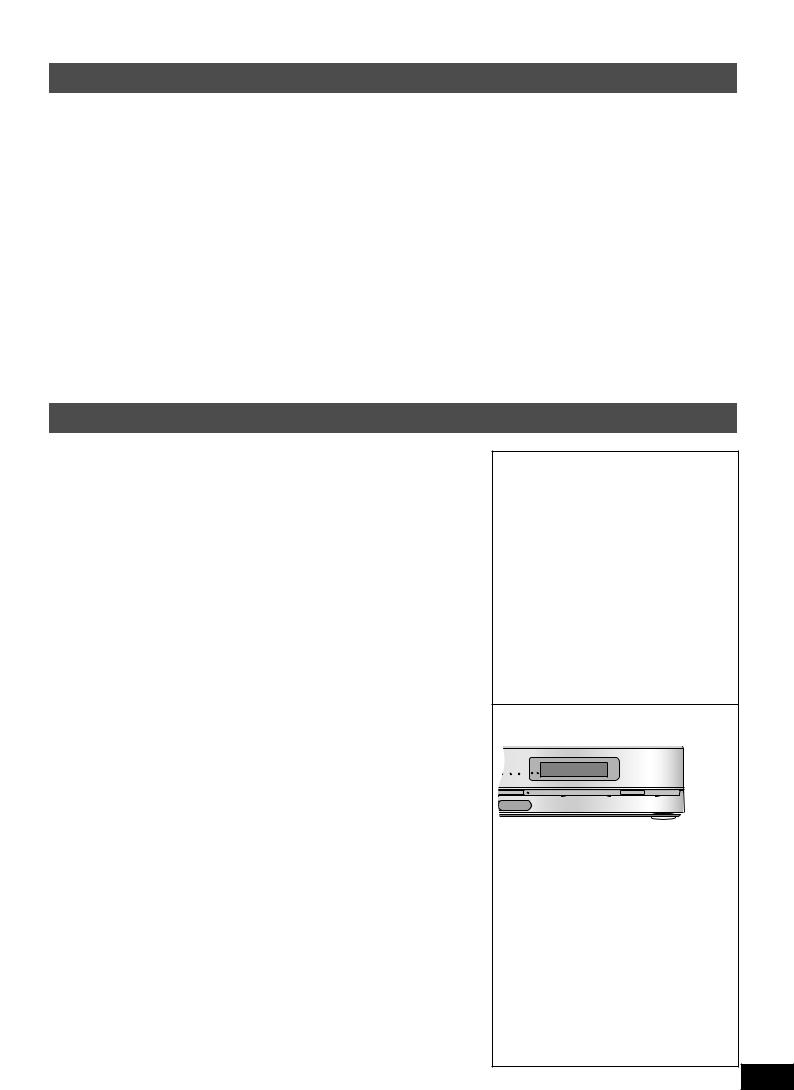
AV Control Receiver
Model No.SA-BX500
Dear customer
Thank you for purchasing this product.
Before connecting, operating or adjusting this product, please read the instructions completely.
Please keep this manual for future reference.
As an ENERGY STAR Partner*, Panasonic has determined that this product meets the ENERGY STAR
 guidelines for energy efficiency.
If you have any questions, contact
In the U.S.A.: 1-800-211-PANA (7262) In Canada: 1-800-561-5505
For U.S.A. only
The warranty can be found on page 57.
For Canada only
The warranty can be found on page 58.
*For Canada only:The word “Participant” is used in place of the word “Partner”.
PP En Cf |
RQT9223-Y |
|
H0608VC0 |
CAUTION
RISK OF ELECTRIC SHOCK
DO NOT OPEN
CAUTION:TO REDUCETHE RISK OF ELECTRIC
SHOCK, DO NOT REMOVE SCREWS.
NO USER-SERVICEABLE PARTS INSIDE.
REFER SERVICINGTO QUALIFIED
SERVICE PERSONNEL.
The lightning flash with arrowhead symbol, within an equilateral triangle, is intended to alert the user to the presence of uninsulated “dangerous voltage” within the product’s enclosure that may be of sufficient magnitude to constitute a risk of electric shock to persons.
The exclamation point within an equilateral triangle is intended to alert the user to the presence of important operating and maintenance (servicing) instructions in the literature accompanying the appliance.
CAUTION!
Do not place anything on top of this unit or block the heat radiation vents in any way. In particular, do not place DVD recorder or CD/ DVD players on this unit as heat radiated from it can damage your software.
CAUTION
Danger of explosion if battery is incorrectly replaced. Replace only with the same or equivalent type recommended by the manufacturer. Dispose of used batteries according to the manufacturer’s instructions.
Listening caution
EST. 1924
Selecting fine audio equipment such as the unit you’ve just purchased is only the start of your musical enjoyment.Now it’s time to consider how you can maximize the fun and excitement your equipment offers.This manufacturer and the Electronic Industries Association’s Consumer Electronics Group want you to get the most out of your equipment by playing it at a safe level.One that lets the sound come through loud and clear without annoying blaring or distortion-and, most importantly, without affecting your sensitive hearing.
We recommend that you avoid prolonged exposure to excessive noise.
Sound can be deceiving.Over time your hearing “comfort level” adapts to higher volumes of sound.So what sounds “normal” can actually be loud and harmful to your hearing.
Guard against this by setting your equipment at a safe level BEFORE your hearing adapts.
To establish a safe level:
•Start your volume control at a low setting.
•Slowly increase the sound until you can hear it comfortably and clearly, and without distortion.
Once you have established a comfortable sound level:
• Set the dial and leave it there.
Taking a minute to do this now will help to prevent hearing damage or loss in the future.After all, we want you listening for a lifetime.
2
RQT9223
WARNING:
TO REDUCETHE RISK OF FIRE, ELECTRIC SHOCK OR PRODUCT DAMAGE,
*DO NOT EXPOSETHIS APPARATUSTO RAIN, MOISTURE, DRIPPING OR SPLASHING ANDTHAT NO OBJECTS FILLED WITH LIQUIDS, SUCH AS VASES, SHALL BE PLACED ONTHE APPARATUS.
*USE ONLYTHE RECOMMENDED ACCESSORIES.
*DO NOT REMOVETHE COVER (OR BACK);THERE ARE NO USER SERVICEABLE PARTS INSIDE. REFER SERVICINGTO QUALIFIED SERVICE PERSONNEL.
CAUTION!
DO NOT INSTALL OR PLACETHIS UNIT IN A BOOKCASE, BUILT-IN CABINET OR IN ANOTHER CONFINED SPACE. ENSURETHE UNIT IS WELL VENTILATED.TO PREVENT RISK OF ELECTRIC SHOCK OR FIRE HAZARD DUETO OVERHEATING, ENSURE THAT CURTAINS AND ANY OTHER MATERIALS DO NOT OBSTRUCTTHE VENTILATION VENTS.
The socket outlet shall be installed near the equipment and easily accessible.
The mains plug of the power supply cord shall remain readily operable.
To completely disconnect this apparatus from the AC Mains, disconnect the power supply cord plug from AC receptacle.
HDMI, the HDMI logo and High-Definition Multimedia Interface are trademarks or registered trademarks of HDMI Licensing LLC.
HDAVI Control™ is a trademark of Matsushita Electric Industrial Co., Ltd.
EZ Sync™ is a trademark of Matsushita Electric Industrial Co., Ltd.
VIERA Link™ is a trademark of Matsushita Electric Industrial Co., Ltd.
Manufactured under license from Dolby Laboratories.
Dolby, Pro Logic, and the double-D symbol are trademarks of Dolby Laboratories.
Manufactured under license under U.S. Patent #’s: 5,451,942; 5,956,674; 5,974,380; 5,978,762; 6,226,616; 6,487,535 & other U.S. and worldwide patents issued & pending. DTS is a registered trademark and the DTS logos, Symbol, DTS-HD and DTS-HD Master Audio are trademarks of DTS, Inc.
© 1996-2007 DTS, Inc. All Rights Reserved.
THE FOLLOWING APPLIES ONLY IN CANADA.
This device complies with RSS-210 of the IC Rules. Operation is subject to the following two conditions:
(1)This device may not cause harmful interference,
(2)This device must accept any interference received, including interference that may cause undesired operation of the device.
-If you see this symbol-
Information on Disposal in other Countries outside the European Union
This symbol is only valid in the European Union.
If you wish to discard this product, please contact your local authorities or dealer and ask for the correct method of disposal.

IMPORTANT SAFETY INSTRUCTIONS
Read these operating instructions carefully before using the unit. Follow the safety instructions on the unit and the applicable safety instructions listed below. Keep these operating instructions handy for future reference.
1)Read these instructions.
2)Keep these instructions.
3)Heed all warnings.
4)Follow all instructions.
5)Do not use this apparatus near water.
6)Clean only with dry cloth.
7)Do not block any ventilation openings. Install in accordance with the manufacturer’s instructions.
8)Do not install near any heat sources such as radiators, heat registers, stoves, or other apparatus (including amplifiers) that produce heat.
9)Do not defeat the safety purpose of the polarized or grounding-type plug. A polarized plug has two blades with one wider than the other. A grounding-type plug has two blades and a third grounding prong.The wide blade or the third prong are provided for your safety. If the provided plug does not fit into your outlet, consult an electrician for replacement of the obsolete outlet.
10)Protect the power cord from being walked on or pinched particularly at plugs, convenience receptacles, and the point where they exit from the apparatus.
11)Only use attachments/accessories specified by the manufacturer.
12)Use only with the cart, stand, tripod,
bracket, or table specified by the manufacturer, or sold with the apparatus. When a cart is used, use caution when moving the cart/apparatus combination to avoid injury from tip-over.
13)Unplug this apparatus during lightning storms or when unused for long periods of time.
14)Refer all servicing to qualified service personnel. Servicing is required when the apparatus has been damaged in any way, such as power-supply cord or plug is damaged, liquid has been spilled or objects have fallen into the apparatus, the apparatus has been exposed to rain or moisture, does not operate normally, or has been dropped.
THE FOLLOWING APPLIES ONLY INTHE U.S.A.
FCC Note:
This equipment has been tested and found to comply with the limits for a Class B digital device, pursuant to Part 15 of the FCC Rules.
These limits are designed to provide reasonable protection against harmful interference in a residential installation.This equipment generates, uses and can radiate radio frequency energy and, if not installed and used in accordance with the instructions, may cause harmful interference to radio communications.
However, there is no guarantee that interference will not occur in a particular installation. If this equipment does cause harmful interference to radio or television reception, which can be determined by turning the equipment off and on, the user is encouraged to try to correct the interference by one or more of the following measures:
*Reorient or relocate the receiving antenna.
*Increase the separation between the equipment and receiver.
*Connect the equipment into an outlet on a circuit different from that to which the receiver is connected.
*Consult the dealer or an experienced radio/TV technician for help.
FCC caution: To maintain compliance with FCC regulations, shielded interface cables must be used with this equipment. Operation with non-approved equipment or unshielded cables may result in interference to radio and TV reception. Any changes or modifications not approved by the party responsible for compliance could void the user’s authority to operate this equipment.
This device complies with Part 15 of the FCC Rules.
Operation is subject to the following two conditions:
(1)This device may not cause harmful interference, and
(2)this device must accept any interference received, including interference that may cause undesired operation.
Responsible Party:
Panasonic Corporation of North America
One Panasonic Way
Secaucus, NJ 07094
Support Contact:
Panasonic Consumer Electronics Company
Telephone No.: 1-800-211-PANA (7262)
Listening caution / IMPORTANT SAFETY INSTRUCTIONS Before use
3
RQT9223
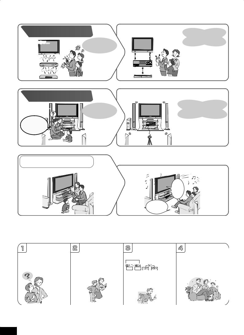
EnjoyingtheHomeTheaterhasbecomeeasy!
Connections |
With SA-BX500! |
Simple connections |
|
|
|
using 2 HDMI cables |
|
Until now... |
Many different |
and 1 stereo connection |
|
cable! |
|||
|
cables were |
||
|
|
||
|
necessary. |
Other connections are also |
|
|
|
||
|
|
possible. |
Settings
With SA-BX500!
Until now… |
Manual setting for |
|
each speaker. |
We must adjust the |
|
speaker settings... |
|
Automatic speaker setup is the easiest way to adjust the speaker settings
( pages 24, 25).
VIERA Link
Previous Home Theater systems required multiple operations.
When you connect the unit to your TV (VIERA) and DVD recorder (DIGA) compatible with VIERA Link
Press just one button and enjoy the Home Theater effect ( pages 32, 33).
The
Home

 Theater
 begins.
One-touch
 playback.
Enjoy the full surround sound from all speakers connected!!
1 |
2 |
TV outputs |
3 |
4 |
How can we enjoy |
|
Just press |
Great!! We can enjoy |
|
2-channel stereo sounds |
||||
TV with surround |
and only front speakers |
SURROUND on the unit |
TV with surround |
|
sound? |
are reproducing stereo |
on the |
sound. |
|
Connections |
remote control |
|
||
|
audio output. |
to enjoy surround sound |
|
|
and settings |
|
|
|
|
|
|
( pages 28, 29). |
|
|
are all |
|
|
|
|
|
|
|
|
|
complete. |
|
|
|
|
4
RQT9223
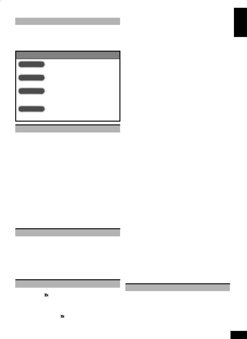
Table of contents
Before use |
|
Listening caution............................................................................ |
2 |
IMPORTANT SAFETY INSTRUCTIONS.......................................... |
3 |
Enjoying the HomeTheater has become easy!............................. |
4 |
Supplied accessories..................................................................... |
6 |
Control guide................................................................................... |
6 |
Quick guide |
|
Step 1 |
|
Placing speakers ................................................................ |
9 |
Step 2 |
|
Connecting speakers ....................................................... |
10 |
Step 3 |
|
Connecting aTV and a |
|
Blu-ray Disc/DVD player................................................... |
12 |
Step 4 |
|
WatchingTV or DVD.......................................................... |
14 |
Preparations |
|
Connections......................................................................... |
16 |
Basic connections........................................................................ |
16 |
Connecting equipment with HDMI terminal .................................. |
16 |
Connecting cables to video and audio terminals |
|
(Connecting equipment without HDMI terminal)........................... |
17 |
Connecting cables to S video and audio terminals.................... |
18 |
Connecting cables to component and |
|
audio terminals ............................................................................. |
19 |
Other connections........................................................................ |
20 |
To enjoy analog sounds................................................................ |
20 |
To enjoy high-quality analog sounds |
|
(Analog 8-channel connections)................................................... |
20 |
To connect the unit to a CD player................................................. |
20 |
To connect the unit for audio or picture recording.......................... |
21 |
To connect the unit to a video camera etc. .................................... |
21 |
Connecting other speakers.......................................................... |
22 |
To connect bi-wire speakers ......................................................... |
22 |
To connect a second pair of front speakers (SPEAKERS B).............. |
22 |
To enjoy wireless audio with SH-FX67.......................................... |
23 |
Connecting antennas ................................................................... |
23 |
Auto speaker setup using the setup microphone..................... |
24 |
Basic operations |
|
Enjoying the HomeTheater................................................. |
26 |
Basic playback.............................................................................. |
26 |
Using surround speakers wirelessly with SH-FX67 ................... |
27 |
To enjoy 7.1 channel playback using 2 sets of SH-FX67............... |
27 |
When you use wireless speakers in another room (MULTI ROOM).... |
27 |
Using SPEAKERS B...................................................................... |
27 |
Playback when making analog 8-channel connections............. |
27 |
Enjoying only withTV speaker..................................................... |
27 |
Enjoying 7.1-channel virtual surround playback........................ |
27 |
Operations |
|
Listening to surround sound .............................................. |
28 |
Dolby Pro Logic ....................................................................... |
28 |
NEO:6............................................................................................. |
28 |
SFC (Sound Field Control) ........................................................... |
28 |
Sound field ................................................................................... |
29 |
Remote controlling sound effects...................................... |
30 |
Adjusting Dolby Pro Logic ’s“MUSIC ”mode......................... |
30 |
Adjusting NEO:6’s“MUSIC ”mode.............................................. |
30 |
Convenient functions.......................................................... |
31 |
Adjusting speaker volumes ......................................................... |
31 |
Silencing speakers temporarily................................................... |
31 |
Displaying the current status....................................................... |
31 |
Using theVIERA Link“HDAVI ControlTM” ........................... |
32 |
Enjoying the HomeTheater through one-touch operations ...... |
33 |
Using the sound menu ........................................................ |
34 |
Adjusting the speaker level.......................................................... |
34 |
Adjusting the bass........................................................................ |
34 |
Adjusting the treble ...................................................................... |
34 |
Balancing front speaker volume.................................................. |
35 |
Changing the audio output (Dual program) ................................ |
35 |
Listening clearly at low volume.................................................... |
35 |
Using whisper mode surround .................................................... |
35 |
Using the setup menu.......................................................... |
36 |
Basic operation............................................................................. |
36 |
Adjusting the brightness of the display ...................................... |
37 |
Using sleep timer.......................................................................... |
37 |
Setting speakers and their sizes.................................................. |
37 |
Setting distances.......................................................................... |
37 |
Setting the lowpass filter.............................................................. |
38 |
Changing auto speaker settings ................................................. |
38 |
To return speakers to factory settings ........................................... |
38 |
Setting the unit against automatic polarity adjustment.................. |
38 |
Adjusting the high-frequency sound quality of the set frequency |
|
response ...................................................................................... |
38 |
Making bi-wire setting .................................................................. |
38 |
Setting the speaker impedance ................................................... |
38 |
Changing the input settings......................................................... |
39 |
Setting the placement positions for surround speakers............ |
39 |
Setting wireless speakers............................................................ |
39 |
Setting input signals..................................................................... |
39 |
Adjusting input levels for external terminals.............................. |
39 |
Reducing standby power consumption |
|
(power save mode)........................................................................ |
40 |
SettingVIERA Link to“OFF ”........................................................ |
40 |
Switching the attenuator .............................................................. |
40 |
Adjusting the time lag by delaying audio |
|
output when pictures onTV arrives after sounds....................... |
40 |
Changing the volume display ...................................................... |
40 |
Reset (factory settings)................................................................ |
40 |
Using headphones............................................................... |
41 |
Recording............................................................................. |
41 |
Remote controlling aTV or DVD recorder etc....................... |
42 |
Remote controlling aTV,cable box and satellite receiver ............... |
42 |
Using two or more Panasonic equipment |
|
(a mini component system,an AV amp etc.)............................... |
42 |
Remote controlling a DVD recorder............................................. |
43 |
Remote controlling a Blu-ray Disc/DVD player........................... |
44 |
Entering a code to operate other equipment .............................. |
45 |
Playing an iPod on this unit................................................. |
47 |
Playing music recorded on iPod.................................................. |
47 |
Listening to the Radio ......................................................... |
48 |
Preset tuning................................................................................. |
48 |
Auto presetting ............................................................................. |
48 |
Manual presetting......................................................................... |
48 |
Listening to preset stations (using the remote control).................. |
48 |
Manual tuning................................................................................ |
49 |
Tuning directly using the numbered buttons.................................. |
49 |
Using the unit................................................................................ |
49 |
Using the remote control............................................................... |
49 |
Reducing excessive noise ........................................................... |
49 |
FM frequency step ........................................................................ |
49 |
Reference |
|
Other information ................................................................ |
50 |
Glossary............................................................................... |
52 |
Error messages.................................................................... |
53 |
Troubleshooting guide........................................................ |
54 |
Maintenance......................................................................... |
55 |
Specifications...................................................................... |
56 |
LimitedWarranty (Only for the U.S.A.)................................ |
57 |
LimitedWarranty (Only for Canada) ................................... |
58 |
Product Service ................................................................... |
59 |
Enjoying the HomeTheater has become easy! /Table of contents Before use
5
RQT9223
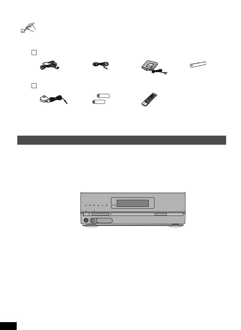
Supplied accessories
Please check and identify the supplied accessories.
Use numbers indicated in parentheses when asking for replacement parts. (Product numbers correct as of June 2008.These may be subject to change.)
Only for the U.S.A.:To order accessories, refer to “Accessory Purchases” on page 57.
Only for Canada:To order accessories, call the dealer from whom you have made your purchase.
1 AC power supply cord |
|
1 FM indoor antenna |
|
1 AM loop antenna |
|
1 Front terminal cover |
||
(K2CB2CB00021) |
|
(RSA0007-M) |
|
(N1DAAAA00002) |
|
(RGK2137A-K) |
||
|
|
|
||||||
|
|
|
|
|
|
|
|
|
1 Setup microphone |
|
2 Batteries |
|
1 Remote control |
|
|
|||
(L0CBAB000128) |
|
|
|
(N2QAKB000069) |
|
|
|
(Canada only)
The enclosed Canadian French label sheet corresponds to the English display on the front and back sides of the unit.
Control guide
This unit
Lights on when playing a disc using multi-channel LPCM format
Lights on when BI-AMP is on ( page 51)
Lights on when playing a disc using |
|
|
|
|
For switching the surround playback on |
||
high definition audio format such as |
|
|
|
|
and off (The indicator lights up when the |
||
Blu-ray Disc |
|
|
|
|
surround playback is on.) ( page 29) |
|
|
Lights on when the following multi- |
|
|
|
|
Lights up under the condition that using the |
||
channel playback settings are used |
|
|
|
|
digital transmitter (SH-FX67) is possible |
||
• When playing multi-channel sources |
|
|
|
|
|
|
|
• When using surround effects for two- |
|
|
|
|
|
|
For selecting input |
channel sources, etc. |
|
|
|
|
|
|
|
Standby indicator [^] |
|
|
|
|
|
|
sources ( pages 15, |
|
|
|
|
|
|
26 and 41) |
|
When the unit is connected to the |
|
|
|
|
|
VOLUME |
|
|
|
|
|
|
|
||
|
|
|
|
INPUT SELECTOR |
|
For adjusting volumes |
|
household AC outlet, this indicator lights |
|
|
|
|
|
|
|
up in standby mode and goes out when |
|
|
|
WIRELESS READY |
|
|
( pages 15, 26 and |
MULTI CH |
|
MULTI CH |
SURROUND M.ROOM |
|
|
||
PROCESSING |
TrueHD D+ |
DTS-HD LPCM |
BI-AMP |
|
|
41) |
|
the unit is turned on. |
|
|
|
|
_ |
+ |
|
Standby/on switch [POWER 8] |
|
|
|
|
|
|
For tuning the radio |
|
|
|
|
|
|
( page 49) |
|
Press to switch the unit from on to |
POWER |
SURROUND |
SPEAKERS A |
SPEAKERS B AUTO SPEAKER SETUP |
RETURN -SETUP OK TUNE |
|
|
|
|
|
|
|
|
||
|
SETUP MIC |
|
AUX |
|
|
|
|
standby mode or vice versa. In standby |
|
|
|
|
|
|
For SETUP operations |
mode, the unit is still consuming a small |
|
|
S VIDEO |
VIDEO L - AUDIO - R |
|
|
|
|
|
|
|
|
|
( page 36) |
|
amount of power. |
|
|
|
|
|
|
|
|
|
|
|
|
|
|
|
For connecting headphones |
|
|
|
|
|
|
Lights on during the |
( page 41) |
|
|
|
|
|
|
|
|
|
|
|
|
|
auto speaker setup |
|
|
|
|
|
|
|
|
|
For connecting the setup microphone |
|
|
|
|
|
|
( page 24) |
( page 24) |
|
|
|
|
|
|
For selecting front |
|
|
|
|
|
|
|
speakers ( pages 24, |
For connecting a video camera etc. |
26 and 27) |
|
( page 21) |
||
|
Display
Lights on when 2-channel mix is functioning
( pages 27, 41 and 51)
Radio display |
Lights on when |
Unit display |
Lights on when PCM FIX is selected |
sleep timer is set |
|||
|
( page 37) |
|
( page 39) |
2CH MIX |
TUNED |
MONO ST |
M SLEEP |
DIGITAL INPUT |
Lights on when the |
||
SPEAKERS |
|
|
ft |
DTS96/24DTS-ES PCM |
|||
|
|
corresponding digital |
|||||
BI-WIRE |
|
|
kHz |
DIGITAL EX |
EX |
source is input ( page 50) |
|
A |
B |
|
|
MHz |
|
|
|
|
Displays front speakers in use |
General display |
Frequency unit indicators |
6 |
( pages 15, 24, 26 and 27) |
|
|
|
|
|
RQT9223
Rear Panel
Speaker terminals ( pages 10, 11 and 22) HDMI terminals ( pages 12, 13, 16 and 32) S video terminals ( pages 18 and 21)
|
FRONT A |
FRONT B |
|
CENTER |
SURROUND |
|
SURROUND BACK |
|
R |
LF |
L BI-WIRE R HF |
L |
|
R |
L |
R |
L |
A OR B/BI-WIRE : 4-8 Ω / EACH SPEAKER (CHAQUE) |
6-8 Ω / EACH SPEAKER (CHAQUE) |
|
A AND B : 6-8 Ω / EACH SPEAKER (CHAQUE) |
|
|
|
Class2 wiring |
|
SPEAKERS |
HAUT-PARLEURS |
AC IN~
|
OUT |
|
IN |
|
|
IN |
|
|
IN |
|
|
|
|
|
|
|
|
|
|
(DVD RECORDER) |
(BD/DVD PLAYER) |
(CABLE/SAT) |
|
|
|
|
|
|
|
||||
|
|
|
HDMI 1 |
|
HDMI 2 |
|
HDMI 3 |
|
|
|
|
|
|
|
||
|
|
COMPONENT VIDEO |
|
|
|
|
S VIDEO |
|
|
|
|
|
|
|
||
Y |
|
|
|
|
|
|
|
|
|
|
|
|
|
|
|
|
|
|
|
|
OUT |
BD/ |
IN |
OUT |
IN |
IN |
IN |
IN |
|
|
|
|
|
PB |
|
|
|
TV MONITOR DVD PLAYER |
DVD RECORDER |
VCR |
CABLE/SAT |
GAME |
|
|
|
|
|
|||
|
|
|
|
|
|
|
|
VIDEO |
|
|
|
|
|
|
|
|
PR |
|
|
|
|
|
|
|
|
|
|
|
(DVD RECORDER) |
(BD/DVD PLAYER) |
(TV) |
(CD) |
|
|
|
|
|
|
|
|
|
|
|
|
|
OPTICAL 1 |
OPTICAL 2 |
OPTICAL 3 |
COAXIAL |
|
OUT |
IN |
(BD/ IN |
IN |
OUT |
BD/ |
IN |
OUT |
IN |
IN |
IN |
IN |
|
|
DIGITAL IN |
|
|
TV MONITOR (DVDRECORDER) DVD PLAYER) (CABLE/SAT) TV MONITOR DVD PLAYER |
DVD RECORDER |
VCR |
CABLE/SAT |
GAME |
|
|
|
|
FM ANT |
|||||||
|
1 |
2 |
3 |
|
|
|
|
|
|
|
|
|
|
|
|
|
|
|
CENTER |
|
|
|
AUDIO |
|
|
|
|
|
|
|
75 Ω |
||
|
|
|
|
|
|
|
|
|
|
|
|
DC OUT/SORTIE C.C. |
|
|||
|
|
|
|
|
|
|
|
|
|
|
|
|
|
|||
L |
|
|
|
|
|
|
|
|
|
|
|
|
|
5V 500mA MAX |
|
|
|
|
|
|
|
|
|
|
|
|
|
|
|
OPTION V.1 |
|
|
|
|
|
|
|
|
|
|
|
|
|
|
|
|
|
|
LOOP |
|
R |
|
|
|
|
|
|
|
|
|
|
|
|
|
LOOP ANT EXT |
|
|
|
|
|
|
|
|
|
|
|
|
|
|
|
|
|
||
IN |
|
SUBWOOFER |
SURROUND BACK |
SURROUND |
FRONT |
OUT |
IN |
IN |
IN |
IN |
IN |
|
GND |
|
AM ANT |
|
|
OUT |
|
||||||||||||||
CD |
|
BD/DVD PLAYER / ANALOG 8CH IN |
DVD RECORDER |
VCR |
CABLE/SAT |
GAME |
TV |
SUBWOOFER |
|
|
||||||
Digital transmitter terminal
( page 23)
Digital input terminals ( pages 12, 13, 16 to 20 and 32)
Option port terminal ( page 47)
AC inlet |
Exhaust hole |
Component Video |
Video terminals |
Audio terminals |
Antenna terminal |
( page 12) |
(Cooling fan) |
terminals ( page 19) |
( pages 17 and |
( pages 11, 16 to |
( page 23) |
|
|
|
21) |
21) |
|
Remote control
For switching an input source on and off/ Source switching/ Switching remote control
modes ( pages 42 to 46)
Power button 

|
INPUT |
|
For selecting input |
SELECTOR |
|
|
||
sources ( pages 26 |
|
|
and 41) |
|
|
For switching FM or |
CH |
|
AM ( pages 48 and 49) |
||
|
||
For inputting channels |
|
|
TV, cable box and satellite |
|
|
receiver ( page 42) |
|
|
DVD recorder |
|
|
( page 43) |
|
|
Radio ( page 48) |
|
|
For selecting a track or |
|
|
chapter |
|
|
DVD recorder ( page 43) |
|
|
Blu-ray Disc/DVD player |
|
|
( page 44) |
|
|
For inputting frequencies |
|
|
( page 49) |
|
For playing 8 channels sources ( page 27)
For selecting a channel TV, cable box and satellite receiver ( page 42)
DVD recorder ( page 43) Radio ( page 48)
For adjusting volumes ( pages 14, 15, 26 and 41)
For silencing speakers temporarily ( page 31)
For operating other equipment
( pages 33 and 42 to 44)
For confirming speaker output ( page 14)/For auto speaker setup ( pages 24 and 25)/For adjusting speaker level ( page 31)
For listening to surround 

 sounds ( pages 28 to 30)

SOUND MENU
DISPLAY
OPTION
PORT
 SETUP
SETUP
For operating SOUND MENU ( pages 34 and 35)/SETUP ( page 36)
For selecting SOUND MENU ( pages 34 and 35)

 For operating aTV ( page 42)
For changing the display ( pages 31 and 48)
For playing an iPod ( page 47)/For entering SETUP menu items ( page 36)
Batteries
Press on the tab to open.

 (R6/LR6, AA)
Place this side in before the other side when you close.
•Insert so the poles (( and )) match those in the remote control.
•Do not use rechargeable type batteries.
•Do not heat or expose to flame.
•Do not leave the batteries in an automobile exposed to direct sunlight for a long period of time with doors and windows closed.
Use
Remote control signal sensor
|
|
|
VOLUME |
|
|
INPUT SELECTOR |
|
|
|
_ |
+ |
SPEAKERS A SPEAKERS B |
AUTO SPEAKER SETUP |
RETURN -SETUP OK TUNE |
|
AUX |
|
|
|
S VIDEO VIDEO L - AUDIO - R |
|
|
|
|
|
About 7 meters (23 feet) or less |
|
|
|
when you sit directly in front of |
|
|
|
the signal sensor (Exact distance |
|
|
|
depends on angles). |
|
|
|
Transmission window |
|
Caution
•Do not place an object between the signal sensor and the remote control.
•Do not place the signal sensor under direct sunlight or the strong light of an inverter fluorescent lamp.
•Keep the transmission window and the unit’s sensor free from dust.
 When you set the unit in a cabinet
The remote controlling range may decrease depending on the thickness or colors of glass cabinet doors.
Supplied accessories / Control guide Before use
7
RQT9223
Quick guide
This section guides you through the easiest and simplest way to setup the HomeTheater.
Refer to the steps indicated below.The steps 1 to 4 indicate the method one by one from when you purchase the unit until you can enjoy the HomeTheater.
•Turn off all equipment before making any connections.
•Peripheral equipment sold separately unless otherwise indicated.
•To connect equipment, refer to the appropriate operating instructions.
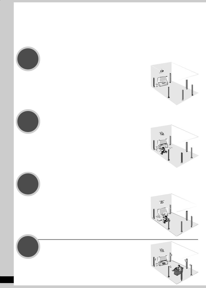
Step |
|
|
Placing speakers ( page 9) |
||
1 |
||
|
You can enjoy the best sound quality by |
|
|
setting speakers properly. |
Step |
|
|
Connecting speakers ( pages 10 and 11) |
||
2 |
||
|
You can install and connect speakers in |
|
|
7.1ch setting. |
Step |
Connecting aTV and a Blu-ray Disc/DVD player |
3 |
( pages 12 and 13) |
Step
4
You can easily enjoy high-quality pictures and sounds.
WatchingTV or DVD ( pages 14 and 15)
You can enjoyTV and DVD with surround sound.
8
RQT9223
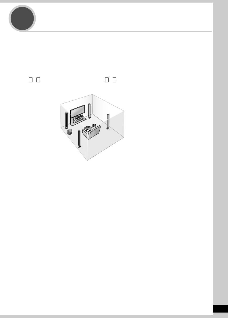
Step |
Placing speakers |
1 |
5.1, 6.1, 7.1 etc. channel playback is possible on this unit.This page introduces speaker settings for 7.1 channel playback.
The ideal placement is to set each speaker (excluding the subwoofer) the same distance away from the listening-viewing position.
Measure the actual distance from each of the connected speakers to the listening-viewing position and perform steps instructed in “Setting distances” ( page 37) or perform steps instructed in “Auto speaker setup using the setup microphone” ( pages 24 and 25) when you cannot install speakers the same distance away.
Example: Front speakers (2), center speaker (1), surround speakers (2), surround back speakers (2) and subwoofer (1)
A – H in the illustration below correspond to A – H in “Connecting speakers” ( pages 10 and 11).
C Center speaker |
A Front speaker (right) |
B Front speaker (left) |
D Surround speaker (right) |
H Active |
F Surround back speaker |
|
(right) |
||
subwoofer |
||
|
||
E Surround speaker (left) |
|
G Surround back speaker (left)
Front speakers (A right, B left)
Place on the left and right of the TV at seated ear height so that there is good coherency between the picture and sound.
C Center speaker
Place underneath or above the center of the TV.
When you do not install the center speaker, sound assigned to it is distributed to front speakers and output from them.
Surround speakers (D right, E left)
Place on the side of or slightly behind the listening-viewing position.
When you do not install surround speakers, sound assigned to them is distributed to front speakers and output from them.
Surround back speakers (F right, G left)
Place behind the listening-viewing position, about 1 meter (3 feet) higher than ear level.
When you do not install any surround back speaker, sound assigned to them is distributed to surround speakers or front speakers and output from them.
H Active Subwoofer
The subwoofer can be placed in any position as long as it is at a reasonable distance from the TV.
Note
• Aim front faces of all speakers at the listening-viewing position for setting.
Placing speakers Quick guide
9
RQT9223
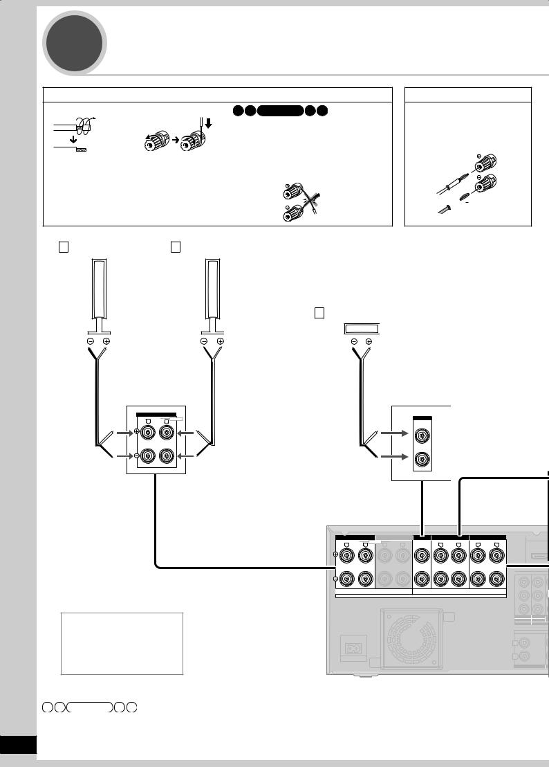
Step |
Connecting speakers |
2 |
How to connect speaker cables
12
Remove the vinyl |
Speaker terminals |
covering the tips of |
|
speaker cables by |
|
twisting it off. |
|
Note
•Connect speaker cables properly to terminals after making sure left and right, and ( and ). Improper connections may cause the unit to develop problems.
•Do not short-circuit speaker cables.The action may damage circuits.
If using 4-mm plug
Turn speaker terminals clockwise and tighten them before inserting plugs into their holes.
 (
(  )
)
 ( )
( )
A Front speaker (right) B Front speaker (left)
C Center speaker
|
FRONT A |
|
|
|
R |
LF |
L |
BI-WIRE |
CENTER |
|
|
|
Rear panel |
|
|
|
|
|
|
|
|
|
FRONT A |
FRONT B |
CENTER |
SURROUND |
|
SURROUND BACK |
|
|
|
|
R LF L BI-WIRE |
R HF L |
|
R |
L |
R |
L |
OUT |
|
|
|
|
|
|
|
|
|
C |
|
|
|
|
|
|
|
|
Y |
|
|
|
A OR B/BI-WIRE : 4-8 Ω / EACH SPEAKER (CHAQUE) |
|
6-8 Ω / EACH SPEAKER (CHAQUE) |
|
|
|||
|
|
A AND B : 6-8 Ω / EACH SPEAKER (CHAQUE) |
|
|
|
||||
|
|
|
|
|
|
|
|
||
|
|
|
SPEAKERS |
|
HAUT-PARLEURS |
|
|
Class2 wiring PB |
|
|
|
|
|
|
|
|
|
PR |
|
Speaker impedance |
|
|
|
|
|
|
OUT |
IN (BD/ |
|
|
|
|
|
|
|
TV MONITOR (DVDRECORDER) DVD |
|||
|
|
|
|
|
|
|
|
|
1 |
Front A: |
4 to 8 Ω |
|
|
|
|
|
|
|
C |
Center: |
6 to 8 Ω |
|
|
|
|
|
|
L |
|
Surround: |
6 to 8 Ω |
AC IN~ |
|
|
|
|
|
R |
|
Surround back: 6 to 8 Ω |
|
|
|
|
|
CD |
|
||
|
|
|
|
|
|
|
|
IN |
SUB |
Note
•Do not forget to take steps instructed in “Auto speaker setup using the setup microphone” ( pages 24 and 25) after connecting a new speaker.
10 • When connecting speakers with the impedance of 4 Ω, make sure to set “4 OHMS ” in “Setting the speaker impedance” on page 38.
RQT9223
Connection cable
|
|
|
|
Speaker cable (not included) |
Monaural connection cable (not included) |
||||||||||||||||||||||||||||
|
|
|
|
|
|
|
|
|
|
|
|
|
|
|
|
|
|
|
|
|
|
|
|
|
|
|
|
|
|
|
|
|
|
|
|
|
|
|
|
|
|
|
|
|
|
|
|
|
|
|
|
|
|
|
|
|
|
|
|
|
|
|
|
|
|
|
|
|
|
|
|
|
|
|
|
|
|
|
|
|
|
|
|
|
|
|
|
|
|
|
|
|
|
|
|
|
|
|
|
|
|
|
|
|
|
|
|
|
|
|
|
|
|
|
|
|
|
|
|
|
|
|
|
|
|
|
|
|
|
|
|
|
|
|
|
|
|
|
|
|
|
|
|
|
|
|
|
|
|
|
|
|
|
|
|
|
|
|
|
|
|
|
|
|
|
|
|
|
|
Use the terminal for the left surround back speaker when you place the speakers for 6.1 channel playback.
D Surround speaker |
E Surround speaker |
F Surround back speaker G Surround back speaker |
||||||||||||||||||||||||||||||||
(right) |
|
|
(left) |
(right) |
|
(left) |
||||||||||||||||||||||||||||
|
|
|
|
|
|
|
|
|
|
|
|
|
|
|
|
|
|
|
|
|
|
|
|
|
|
|
|
|
|
|
|
|
|
|
|
|
|
|
|
|
|
|
|
|
|
|
|
|
|
|
|
|
|
|
|
|
|
|
|
|
|
|
|
|
|
|
|
|
|
|
|
|
|
|
|
|
|
|
|
|
|
|
|
|
|
|
|
|
|
|
|
|
|
|
|
|
|
|
|
|
|
|
|
|
Connecting speakers Quick guide
SURROUND |
|
R |
L |
|
IN |
|
|
IN |
|
|
IN |
|
|
|
|
|
|
|
|
(DVD RECORDER) |
(BD/DVD PLAYER) |
(CABLE/SAT) |
|
|
|
|
|
|
|
||||
|
HDMI 1 |
|
HDMI 2 |
|
HDMI 3 |
|
|
|
|
|
|
|
||
OMPONENT VIDEO |
|
|
|
|
S VIDEO |
|
|
|
|
|
|
|
||
|
|
OUT |
BD/ |
IN |
OUT |
IN |
IN |
IN |
IN |
|
|
|
|
|
|
|
TV MONITOR DVD PLAYER |
DVD RECORDER |
VCR |
CABLE/SAT |
GAME |
|
|
|
|
|
|||
|
|
|
|
|
|
VIDEO |
|
|
|
|
|
|
|
|
|
|
|
|
|
|
|
|
|
|
(DVD RECORDER) |
(BD/DVD PLAYER) |
(TV) |
(CD) |
|
|
|
|
|
|
|
|
|
|
|
OPTICAL 1 |
OPTICAL 2 |
OPTICAL 3 |
COAXIAL |
|
IN |
IN |
OUT |
BD/ |
IN |
OUT |
IN |
IN |
IN |
IN |
|
|
DIGITAL IN |
|
|
PLAYER) (CABLE/SAT) TV MONITOR DVD PLAYER |
DVD RECORDER |
VCR |
CABLE/SAT |
GAME |
|
|
|
|
FM ANT |
|||||
2 |
3 |
|
|
|
|
|
|
|
|
|
|
|
|
|
ENTER |
|
|
|
AUDIO |
|
|
|
|
|
|
|
75 Ω |
||
|
|
|
|
|
|
|
|
|
|
DC OUT/SORTIE C.C. |
|
|||
|
|
|
|
|
|
|
|
|
|
|
|
|||
|
|
|
|
|
|
|
|
|
|
|
|
5V 500mA MAX |
|
|
|
|
|
|
|
|
|
|
|
|
|
|
OPTION V.1 |
|
|
|
|
|
|
|
|
|
|
|
|
|
|
|
LOOP |
|
|
|
|
|
|
|
|
|
|
|
|
|
LOOP ANT EXT |
|
|
WOOFER |
SURROUND BACK |
SURROUND |
FRONT |
OUT |
IN |
IN |
IN |
IN |
IN |
|
GND |
|
AM ANT |
|
OUT |
|
|||||||||||||
BD/DVD PLAYER / ANALOG 8CH IN |
DVD RECORDER |
VCR |
CABLE/SAT |
GAME |
TV |
SUBWOOFER |
|
|
||||||
SURROUND BACK |
|
R |
L |
H Active subwoofer
OUT
SUBWOOFER
11
RQT9223
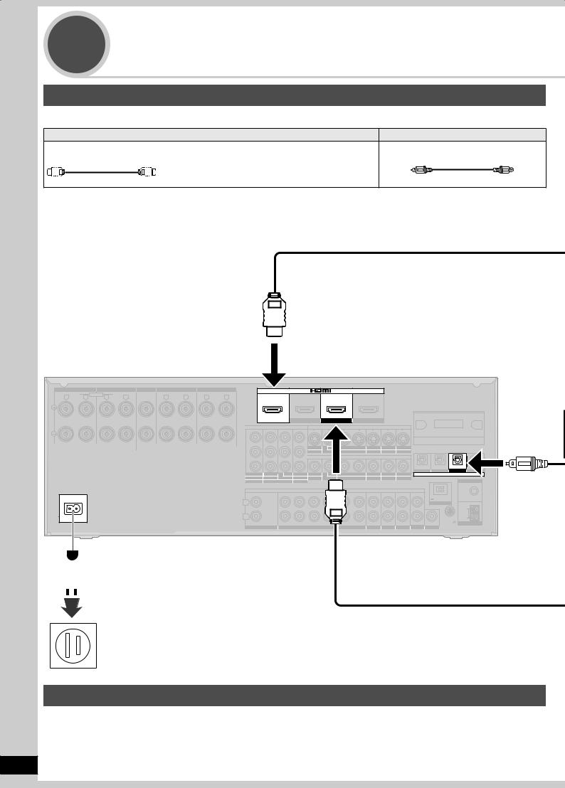
Step |
Connecting aTV and a Blu-ray Disc/ |
||
3 |
DVD player |
|
|
Connecting equipment with HDMI terminal |
|
||
Connection cable |
|
|
|
|
Video and Audio cable |
Audio cable |
|
HDMI Cable (not included) (It is recommended that you use Panasonic’s HDMI cable.) |
Optical fiber cable (not included) |
||
Recommended part number: RP-CDHG10 |
(1.0 m/3.3 ft.), RP-CDHG15 (1.5 m/4.9 ft.), |
|
|
|
RP-CDHG20 |
(2.0 m/6.6 ft.), RP-CDHG30 (3.0 m/9.8 ft.), |
|
|
RP-CDHG50 |
(5.0 m/16.4 ft.), etc. |
|
Rear panel
|
FRONT A |
FRONT B |
|
CENTER |
SURROUND |
|
SURROUND BACK |
|
R |
LF |
L BI-WIRE R HF |
L |
|
R |
L |
R |
L |
A OR B/BI-WIRE : 4-8 Ω / EACH SPEAKER (CHAQUE) |
6-8 Ω / EACH SPEAKER (CHAQUE) |
|
A AND B : 6-8 Ω / EACH SPEAKER (CHAQUE) |
|
|
SPEAKERS |
HAUT-PARLEURS |
Class2 wiring |
AC IN~
OUT |
IN |
IN |
IN |
|
(DVD RECORDER) |
(BD/DVD PLAYER) |
(CABLE/SAT) |
|
HDMI 1 |
HDMI 2 |
HDMI 3 |
|
COMPONENT VIDEO |
|
S VIDEO |
Y
|
OUT |
IN |
IN |
IN |
IN |
|
|
PB |
TV MONITOR |
RECORDER |
VCR |
CABLE/SAT |
GAME |
|
|
|
|
VIDEO |
|
|
|
|
|
PR |
|
|
|
|
(DVD RECORDER) |
(BD/DVD PLAYER) |
(TV) |
|
|
|
|
|
|
|
|
|
OPTICAL 1 OPTICAL 2 OPTICAL 3 |
||
OUT |
IN |
(BD/ IN |
IN |
OUT |
IN |
IN |
IN |
IN |
|
DIGITAL IN |
|
TV MONITOR (DVDRECORDER) DVD PLAYER) (CABLE/SAT) TV MONITOR DVD PLAYER |
DVD RECORDER |
VCR |
CABLE/SAT |
GAME |
|
|
FM ANT |
||||
|
1 |
2 |
3 |
|
|
|
|
|
|
|
|
|
|
CENTER |
|
|
|
|
|
|
|
|
75 Ω |
|
|
|
|
|
|
|
|
|
DC OUT/SORTIE C.C. |
|
|
|
|
|
|
|
|
|
|
|
|
|
|
L |
|
|
|
|
|
|
|
|
|
5V 500mA MAX |
|
|
|
|
|
|
|
|
|
|
OPTION V.1 |
|
|
|
|
|
|
|
|
|
|
|
|
|
LOOP |
R |
|
|
|
|
|
|
|
|
|
LOOP ANT |
EXT |
|
|
|
|
|
|
|
|
|
|
||
IN |
|
SUBWOOFER |
SURROUND BACK |
SURROUND |
IN |
IN |
IN |
IN |
IN |
GND |
AM ANT |
|
OUT |
||||||||||
CD |
|
BD/DVD PLAYER / ANALOG 8CH IN |
DVD RECORDER |
VCR |
CABLE/SAT |
GAME |
TV |
SUBWOOFER |
|
||
 AC power supply cord (included)
Household AC outlet (AC 120 V, 60 Hz)
Notes on AC power supply cord
•Connect AC power supply cord after all other cables and cords are connected.
•The included AC power supply cord is for use with this unit only. Do not use it with other equipment.
•Do not use an AC power supply cord from any other type of equipment with this unit.
•The unit’s settings remain effective after the AC power supply cord is removed from the household AC outlet.
12
RQT9223

Note
•This unit incorporates HDMI™ (V.1.3 with Deep Color) technology that can reproduce greater color gradation (4096 steps) when connected to a compatible TV. A lower color gradation (256 steps), without deep color, will be reproduced if connected to a TV which does not support deep color.
•Please use High Speed HDMI Cables that have the HDMI logo (as shown on the cover).
•When outputting 1080p signal, please use the HDMI cables 5.0 meters (16.4 feet) or less.
•The audio signal transmitted through HDMI takes priority when you use both HDMI and digital terminals for connection ( pages 16 to 20).
HDMI input
Digital audio out (optical)
TV |
You need an optical fiber cable for enjoying TV with a digital sound
output.
To enjoy TV with analog surround sound make connection as instructed on page 16.
Connecting the optical fiber cable
Note the shape and fit it
correctly into Do not bend! the terminal.
Standby through function
You can hear DVD sounds, etc. from TV speakers when you turn off the unit connected as shown on this page.This convenient function enables you to enjoy DVD etc. without using the unit late at night.
HDMI
Video/Audio out
Blu-ray Disc/DVD player
“SURROUND”
POWER |
POWER |
|
SURROUND
When connection is complete
|
|
1. Press |
POWER |
to turn the unit on. |
_ |
+ |
2. Press |
SURROUND |
to set surround playback. |
• The “SURROUND” indicator lights on after the setting.
• You can enjoy 2-channel sources with surround playback.
Connecting aTV and a Blu-ray Disc/DVD player Quick guide
13
RQT9223
Step |
WatchingTV or DVD |
4 |
Turn theTV on and switch theTV’s input mode (to “HDMI” and others)
“ ” “SURROUND”
VOLUME
|
|
|
|
|
INPUT SELECTOR |
|
|
|
|
|
|
WIRELESS READY |
|
MULTI CH |
|
|
|
MULTI CH |
SURROUND M.ROOM |
|
PROCESSING |
TrueHD |
D+ |
DTS-HD |
LPCM |
BI-AMP |
|
|
|
|
|
|
_ |
+ |
|
|
|
|
|
|
POWER |
SURROUND |
SPEAKERS A |
SPEAKERS B |
AUTO SPEAKER SETUP |
RETURN |
-SETUP |
OK |
TUNE |
SETUP MIC |
AUX |
S VIDEO |
VIDEO L - AUDIO - R |
SURROUND |
|
SPEAKERS A |
|
|
|
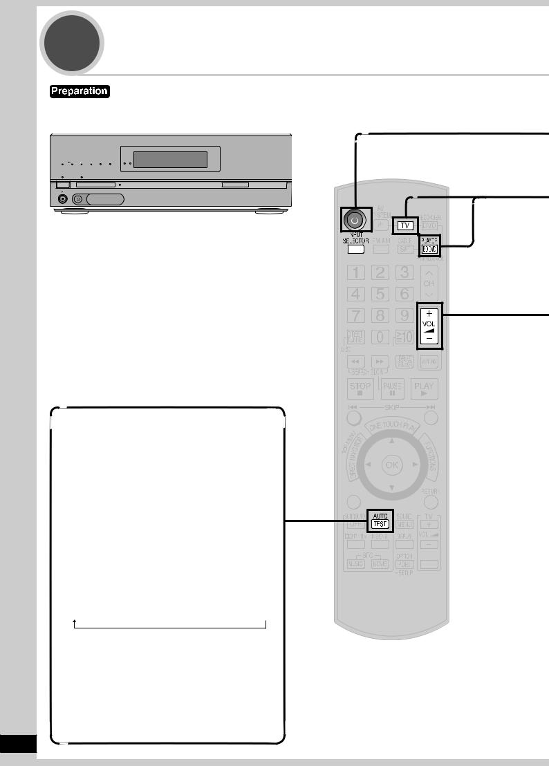
Testing speaker output
You can confirm audio output using the test signal.
1.Press  to turn the unit on.
2.Press 


 to select an input source other than “TV ” or “BD/DVD P. ”.
3.Press  to adjust the volume range between –30dB and –35dB.
4.Press TESTAUTO to test audio output from all connected speakers.
•Speakers are displayed in the following order. (The test signal is output only when the connected speaker is displayed.)
L → C → R → RS → SBR → SBL → LS → SUBW
When you feel the volume of each speaker is not balanced with the volume of the front speakers, see page 31 to adjust the volume balance of speakers.
5.Press TESTAUTO to stop the test signal.
6.Lower the volume to the normal listening level using  .
.
14
ENTER
SUB MENU
S
TV/VIDEO
RQT9223
1 |
To turn the unit on |
• The standby indicator “^” goes off when you turn the unit on. |
Press |
• Confirm if “ A ” appears on the display on the unit. |
|
If “ A ” is not displayed, press [SPEAKERS A]. |
• Check the “SURROUND” indicator is lighting up. If not, press [SURROUND] on the unit to set surround playback
( pages 13 and 29).
2To select “TV ” or “BD/DVD P. ”.
Press  or
or 
3 |
|
|
WatchTV or DVD |
|
|
|
|
|
|
|
• You can enjoy a variety of surround effects ( pages 28 to 30). |
4 |
|
|
To adjust the volume |
|
|
|
|
|
|
Press |
Volume range: |
|
– – dB (minimum), – 79dB to 0dB (maximum) |
To finish watching
Be sure to reduce the volume and press [^] to turn the unit to standby.
Operations on the unit
|
1 |
To turn the unit on |
|
|
|
|
|
Press POWER |
|
2 |
To select “TV ” or “BD/DVD P. ” |
VOLUME |
INPUT SELECTOR |
|
INPUT SELECTOR |
|
Turn |
|
|
|
|
|
|
WIRELESS READY |
|
|
|
|
|
|
|
MULTI CH |
|
|
|
MULTI CH |
BI-AMP |
SURROUND M.ROOM |
|
|
|
|
|
|
|
PROCESSING |
TrueHD |
D+ |
DTS-HD |
LPCM |
|
|
|
|
|
|
3 |
|
|
|
|
|
|
|
|
|
|
|
|
_ |
+ |
WatchTV or DVD |
|
POWER |
|
SURROUND SPEAKERS A |
SPEAKERS B |
AUTO SPEAKER SETUP |
RETURN |
-SETUP |
OK |
TUNE |
|
|
|||
|
SETUP MIC |
|
|
AUX |
|
|
|
|
|
|
|
|
|
|
|
|
|
S VIDEO |
VIDEO L - AUDIO - R |
|
|
|
|
|
|
|
|
|
|
|
|
|
|
|
|
|
|
|
|
4 |
To adjust the volume |
|
|
|
|
|
|
|
|
|
|
|
|
VOLUME |
|
Turn
_ |
+ |
|
WatchingTV or DVD Quick guide
15
RQT9223
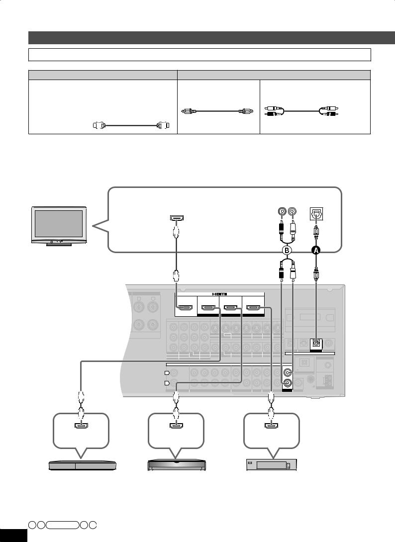
Connections
Basic connections
Connecting equipment with HDMI terminal
Connection cable
Video and Audio cable |
Audio cable |
HDMI cable (not included) |
Optical fiber cable |
Stereo connection cable |
|
Recommended part number: |
(not included) |
(not included) |
|
RP-CDHG10 (1.0 m/3.3 ft.), RP-CDHG15 (1.5 m/4.9 ft.), |
|
|
|
RP-CDHG20 |
(2.0 m/6.6 ft.), RP-CDHG30 (3.0 m/9.8 ft.), |
|
White (L) |
RP-CDHG50 |
(5.0 m/16.4 ft), etc. |
|
Red (R) |
HDMI cable notes
•It is recommended that you use Panasonic’s HDMI cable.
•This unit incorporates HDMI™ (V.1.3 with Deep Color) technology.
•Please use High Speed HDMI Cables that have the HDMI logo (as shown on the cover).
•When outputting 1080p signal, please use the HDMI cables 5.0 meters (16.4 feet) or less.
To enjoyTV with surround sound, make connection or shown below according to your equipment.
TV |
Audio out |
Digital audio |
|
(R) (L) |
out (optical) |
||
|
|||
|
HDMI input |
|
Rear panel
SURROUND |
SURROUND BACK |
|
|
|
|
|
|
|
|
|
L |
R |
L |
OUT |
IN |
IN |
|
|
IN |
|
|
|
|
|
|
(DVD RECORDER) |
(BD/DVD PLAYER) |
(CABLE/SAT) |
|
|
||
|
|
|
|
HDMI 1 |
HDMI 2 |
|
|
HDMI 3 |
|
|
|
|
|
|
COMPONENT VIDEO |
|
|
S VIDEO |
|
|
|
|
|
|
Y |
|
|
|
|
|
|
|
|
CHAQUE) |
|
|
OUT |
BD/ IN |
OUT |
IN |
IN |
IN |
IN |
|
|
|
|
|||||||
|
|
Class2 wiring |
PB |
TV MONITOR DVD PLAYER |
DVD RECORDER |
VCR |
CABLE/SAT |
GAME |
||
|
VIDEO |
|
|
|
PR |
(DVD RECORDER) |
(BD/DVD PLAYER) |
(TV) |
(CD) |
|
||||
|
OPTICAL 1 |
OPTICAL 2 |
OPTICAL 3 |
COAXIAL |
OUT |
IN |
(BD/ IN |
IN |
OUT |
BD/ IN |
OUT |
IN |
IN |
IN |
IN |
DIGITAL IN |
|
TV MONITOR (DVDRECORDER) DVD PLAYER) (CABLE/SAT) TV MONITOR DVD PLAYER |
DVD RECORDER |
VCR |
CABLE/SAT |
GAME |
|
FM ANT |
||||||
|
1 |
2 |
3 |
|
|
|
|
|
|
|
|
|
|
|
CENTER |
|
|
AUDIO |
|
|
|
|
|
75 Ω |
|
|
|
|
|
|
|
|
|
|
|
DC OUT/SORTIE C.C. |
|
|
|
|
|
|
|
|
|
|
|
|
|
5V 500mA MAX |
|
L |
|
|
|
|
|
|
|
|
|
|
OPTION V.1 |
|
|
|
|
|
|
|
|
|
|
|
|
|
LOOP |
R |
|
|
|
|
|
|
|
|
|
|
LOOP ANT |
EXT |
IN |
|
SUBWOOFER |
SURROUND BACK |
SURROUND |
FRONT |
OUT |
IN |
IN |
IN |
IN |
GND |
AM ANT |
|
OUT |
|||||||||||
CD |
|
BD/DVD PLAYER / ANALOG 8CH IN |
DVD RECORDER |
VCR |
CABLE/SAT |
GAME |
TV SUBWOOFER |
|
||||
HDMI |
HDMI |
HDMI |
Video/Audio out |
Video/Audio out |
Video/Audio out |
DVD recorder |
Blu-ray Disc/DVD player |
Cable box, satellite receiver, etc. |
HDMI connection
The HDMI input terminal on the unit’s rear is made to specifications that presume connection of a DVD recorder / Blu-ray Disc/ DVD player etc.When other equipment is connected, sounds may not come out of the unit, or pictures shown on the equipment (TV) connected to the HDMI output terminal may be disrupted.
In such cases, see pages 17, 18 and 19 and make connections other than HDMI.
Note
16 • The audio signal transmitted through HDMI takes priority when you use both HDMI and digital terminals for connection ( pages 16 to 20). RQT9223 • You can change the settings on HDMI 3 terminal according to the equipment to connect ( page 39).

•Turn off all equipment before making any connections.
•Peripheral equipment sold separately unless otherwise indicated.
•To connect equipment, refer to the appropriate operating instructions.
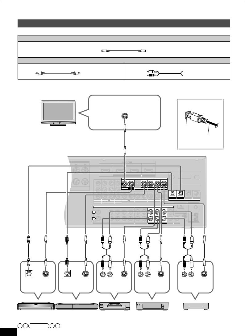
Connecting cables to video and audio terminals (Connecting equipment without HDMI terminal)
Connection cable
Video cable |
Audio cable |
Video connection cable (not included) Optical fiber cable (not included) |
Stereo connection cable (not included) |
|
White (L) |
|
Red (R) |
TV |
VIDEO IN |
To enjoyTV with surround |
Connecting the optical |
|
sound, make connection |
fiber cable |
|
|
|
or instructed on page 16 |
|
|
|
|
|
|
according to your equipment. |
Note the |
|
|
|
|
|
|
|
|
|
|
|
|
Rear panel |
|
shape and fit |
|
|
|
|
|
|
|
|
|
|
|
|
||
it correctly |
Do not |
|
|
|
|
|
|
|
|
|
|
|
|
|
into the |
|
|
|
|
|
|
|
|
|
|
|
|
|
|
bend! |
SURROUND |
|
SURROUND BACK |
|
|
|
|
|
|
|
|
|
||
terminal. |
|
R |
L |
R |
L |
OUT |
IN |
IN |
|
IN |
|
|
|
|
|
|
|
|
|
|
|
|
|
|
|
|
|
|
|
|
|
|
|
|
|
|
(DVD RECORDER) |
(BD/DVD PLAYER) |
(CABLE/SAT) |
|
|
|
||
|
|
|
|
|
|
|
HDMI 1 |
HDMI 2 |
|
HDMI 3 |
|
|
|
|
|
|
|
|
|
|
|
COMPONENT VIDEO |
|
|
S VIDEO |
|
|
|
|
|
|
|
|
|
|
Y |
|
|
|
|
|
|
|
|
|
|
|
|
CHAQUE) |
|
|
OUT |
BD/ IN |
OUT |
IN |
IN |
IN IN |
|
|
|
|
|
|
|
|
|
|
|
||||||
|
|
|
|
|
Class2 wiring |
PB |
TV MONITOR DVD PLAYER |
DVD RECORDER |
VCR |
CABLE/SAT GAME |
|
|
||
|
|
|
|
|
|
|
|
|
|
VIDEO |
|
|
|
|
|
|
|
|
|
|
PR |
|
|
|
|
|
(DVD RECORDER) (BD/DVD PLAYER) |
(TV) |
(CD) |
|
|
|
|
|
|
|
|
|
|
|
|
OPTICAL 1 OPTICAL 2 |
OPTICAL 3 |
COAXIAL |
OUT |
IN |
(BD/ |
IN |
IN |
OUT |
BD/ |
IN |
OUT |
IN |
IN |
IN |
IN |
|
DIGITAL IN |
|
TV MONITOR (DVDRECORDER) DVD PLAYER) (CABLE/SAT) TV MONITOR DVD PLAYER |
DVD RECORDER |
VCR |
CABLE/SAT |
GAME |
|
|
FM ANT |
||||||||
|
1 |
|
2 |
3 |
|
|
|
|
|
|
|
|
|
|
|
|
|
CENTER |
|
|
|
AUDIO |
|
|
|
|
|
|
75 Ω |
||
|
|
|
|
|
|
|
|
|
|
|
|
DC OUT/SORTIE C.C. |
|
||
|
|
|
|
|
|
|
|
|
|
|
|
|
|
|
|
L |
|
|
|
|
|
|
|
|
|
|
|
|
|
5V 500mA MAX |
|
|
|
|
|
|
|
|
|
|
|
|
|
|
OPTION V.1 |
|
|
|
|
|
|
|
|
|
|
|
|
|
|
|
|
|
|
|
|
|
|
|
|
|
|
|
|
|
|
|
|
|
LOOP |
R |
|
|
|
|
|
|
|
|
|
|
|
|
|
LOOP ANT |
EXT |
IN |
|
SUBWOOFER |
SURROUND BACK |
SURROUND |
FRONT |
OUT |
IN |
IN |
IN |
IN |
IN |
GND |
AM ANT |
||
|
OUT |
||||||||||||||
CD |
|
|
BD/DVD PLAYER / ANALOG 8CH IN |
DVD RECORDER |
VCR |
CABLE/SAT |
GAME |
TV |
SUBWOOFER |
|
|||||
Connections Preparations
|
1 |
2 |
|
|
|
|
|
Digital audio VIDEO |
Digital audio VIDEO |
(R) (L) |
VIDEO |
(R) (L) |
VIDEO |
(R) (L) |
VIDEO |
out (optical) OUT |
out (optical) OUT |
Audio out |
OUT |
Audio out |
OUT |
Audio out |
OUT |
Blu-ray Disc/ |
DVD recorder |
VCR |
Cable box or |
DVD player |
|
|
satellite receiver |
 To connect a DVD recorder with built-in VCR
(When the DVD recorder has DVD/VHS terminals, make the following connections.) Connect the DVD output terminal as shown above.
Connect the DVD/VHS output terminal as shown above.
Game
Note
•When you make HDMI connections ( pages 12, 13 and 16), this connection is not necessary.
•The input video signal can be sent out through an output terminal of the same type only.
•You can change the digital input terminal setting according to the equipment to connect ( page 39).
Playback is available with the basic connections ( page 26).
In addition To make high-picture-quality connections ( pages 18 and 19) In addition To enjoy analog sounds ( page 20)
In addition To connect other equipment, etc. ( pages 20 to 23)
17
RQT9223
Connections
Connecting cables to S video and audio terminals
Connection cable
Video cable
S VIDEO connection cable (not included)
Audio cable
Optical fiber cable (not included) |
Stereo connection cable (not included) |
 White (L)

 Red (R)
To enjoyTV with surround sound, make connection orinstructed on page 16 according to your equipment.
TV
|
Connecting the optical |
|
S VIDEO IN |
fiber cable |
|
|
|
|
|
Note the |
|
|
shape and fit |
|
|
it correctly |
Do not |
|
into the |
|
|
bend! |
|
|
terminal. |
|
|
|
|
Rear panel
SURROUND |
|
SURROUND BACK |
|
|
|
|
|
R |
L |
R |
L |
OUT |
IN |
IN |
IN |
|
|
|
|
|
(DVD RECORDER) |
(BD/DVD PLAYER) |
(CABLE/SAT) |
|
|
|
|
|
HDMI 1 |
HDMI 2 |
HDMI 3 |
|
|
|
|
|
COMPONENT VIDEO |
|
S VIDEO |
|
|
|
|
Y |
|
|
|
CHAQUE) |
|
OUT BD/ IN |
OUT |
IN |
IN |
IN |
IN |
Class2 wiring |
PB |
TV MONITOR DVD PLAYER |
DVD RECORDER |
VCR |
CABLE/SAT |
GAME |
|
|
|
|
|
VIDEO |
|
|
|
PR |
|
|
|
|
|
|
|
|
|
|
|
|
(DVD RECORDER) |
(BD/DVD PLAYER) |
(TV) |
(CD) |
||
|
|
|
|
|
|
|
|
|
|
|
|
|
OPTICAL 1 |
OPTICAL 2 |
OPTICAL 3 |
COAXIAL |
||
OUT |
IN |
(BD/ |
IN |
IN |
OUT |
BD/ |
IN |
OUT |
IN |
IN |
IN |
IN |
|
|
DIGITAL IN |
|
|
|
TV MONITOR (DVDRECORDER) DVD PLAYER) (CABLE/SAT) TV MONITOR DVD PLAYER |
DVD RECORDER |
VCR |
CABLE/SAT |
GAME |
|
|
|
|
|
FM ANT |
||||||||
|
1 |
|
2 |
3 |
|
|
|
|
|
|
|
|
|
|
|
|
|
|
|
|
CENTER |
|
|
|
AUDIO |
|
|
|
|
|
|
|
|
75 Ω |
|||
|
|
|
|
|
|
|
|
|
|
|
|
DC OUT/SORTIE C.C. |
|
|
||||
|
|
|
|
|
|
|
|
|
|
|
|
|
|
|
|
|||
L |
|
|
|
|
|
|
|
|
|
|
|
|
|
|
5V 500mA MAX |
|
|
|
|
|
|
|
|
|
|
|
|
|
|
|
|
|
OPTION V.1 |
|
|
|
|
|
|
|
|
|
|
|
|
|
|
|
|
|
|
|
|
|
|
|
|
|
|
|
|
|
|
|
|
|
|
|
|
|
|
|
|
LOOP |
|
R |
|
|
|
|
|
|
|
|
|
|
|
|
|
|
LOOP ANT |
EXT |
|
|
|
|
|
|
|
|
|
|
|
|
|
|
|
|
|
|
|||
IN |
|
SUBWOOFER |
SURROUND BACK |
SURROUND |
FRONT |
OUT |
IN |
IN |
IN |
IN |
IN |
|
GND |
|
|
AM ANT |
||
|
OUT |
|
|
|||||||||||||||
CD |
|
|
BD/DVD PLAYER / ANALOG 8CH IN |
DVD RECORDER |
VCR |
CABLE/SAT |
GAME |
TV |
SUBWOOFER |
|
|
|
||||||
Digital audio SVIDEO |
Digital audio SVIDEO |
(R) (L) |
SVIDEO |
(R) (L) |
SVIDEO |
(R) (L) |
SVIDEO |
out (optical) OUT |
out (optical) OUT |
Audio out |
OUT |
Audio out |
OUT |
Audio out |
OUT |
Blu-ray Disc/ |
DVD recorder |
VCR |
Cable box or |
Game |
DVD player |
|
|
satellite receiver |
|
Note |
|
|
|
|
18 • The input video signal can be sent out through an output terminal of the same type only.
RQT9223 • You can change the digital input terminal setting according to the equipment to connect ( page 39).
Loading...