

Panasonic ER-VS01 Installation Manual
INSTRUCTION MANUAL
Static Remover
Ionizer㨯Spot type
ER-VS01
Thank you very much for using SUNX products. Please read this Instruction
Manual carefully and thoroughly for the correct and optimum use of this product.
Kindly keep this manual in a convenient place for quick reference.
٨
This product is to remove static electricity for industrial use. Never use this product for medical equipment etc. relating to maintenance/supervision of human life or body, for prevention of accidents which damage a human life or properties, or for safety
maintenance.
٨
Since the tip of the discharge needle is pointed, take sufficient
care in handling the discharge needle, or injuries may result.
Do not use this product near or around surroundings containing
٨
any dangerous materials, such as combustible material and
flammable material.
The discharge needle gathers dust after a long period of use. In
٨
WARNING
1
OUTLINE
٨
This product is a compact, corona discharge type electrostatic charge removal device.
٨
This product neutralizes electrostatic charge from charged objects quickly
and effectively.
This product removes dust stuck to charged objects due to static electricity,
٨
and keeps such objects free from electrostatic dust.
2
CAUTIONS
٨
Make sure to use the DC power supply insulated by an isolation transformer
etc. for this product. If an auto-transformer etc. (single winding transformer) is
used, this product or the power supply may get damaged due to short-circuit.
٨
If the air supplied to this product is ON/OFF by a solenoid valve etc., turn the main
power on/off simultaneously. [Discharge halt (DSC OFF) input should be used]
٨
If corona discharge is done without supplying air, the amount of ozone generation increases remarkably.
Do not use during the initial transient time (0.5 sec.) after the power supply
٨
is switched on.
If the power supply is switched on immediately after being switched off, fault
٨
output may be generated. After the power supply is switched off, keep an
interval of 1 sec. or more, before switching it on again.
٨
Do not use this product beyond its rated specifications. Doing so can cause
product breakdown, non-function, or damage. Further, it will also cause a
marked reduction in product life.
٨
Never disassemble, repair, modify, or misuse this product, as it can cause
accident or malfunction.
٨
Do not throw this product in fire. There is a danger of it exploding, or generating poisonous gas.
Since this product emits ozone into the atmosphere, circulate the air if it is
٨
foul-smelling. If ozone stays for long period, metals etc. may oxidize/decay.
Further, do not try to confirm the foul-smelling ozone by drawing your face
near the nozzle outlet. There is a danger of hurting your nose, throat, etc.
If this product is used immediately after storage in a high-humidity environ-
٨
ment, its ion balance may remain lost. Therefore, before use, leave this
product in the atmosphere with a temperature of +25 or so and a relative
humidity of 30% RH for over 8 hours.
Do not use this product in steamy or dusty places and in places where water
٨
splashes or spatter flies when welding.
Make sure that the power supply is off while wiring and inspection. Other-
٨
wise, there is a danger of accident, electric shock or malfunction.
After wiring, reconfirm the wiring connections before switching on the power
٨
supply.
Take care that wrong wiring will damage the product.
٨
Verify that the supply voltage variation is within the rating.
٨
٨
If power is supplied from a commercial switching regulator, ensure that the frame
ground (F.G.) terminal of the power supply is connected to an actual ground.
٨
In case a surge is generated in the used power supply, connect a surge absorber to the supply and absorb the surge.
Do not run the wires together with high-voltage lines or power lines or put
٨
them in the same raceway. This can cause malfunction due to induction.
Confirm the wiring and piping state before supplying power or air. Wrong wir-
٨
ing and piping may cause malfunction.
Use air (dried clean air) for the fluid. Fluid other than air (dried clean air) or
٨
that containing corrosive gas may cause accident or malfunction.
order to prevent accident or product malfunction, clean up the discharge needle, periodically once every two weeks or so, or this
product will be unable to exert the charge removal performance.
٨
Be sure to ground the main body of this product via ground terminal
to ensure electric shock prevention and reliable charge removal.
Since the discharge needle is live with high voltage, never touch
٨
the discharge needle, or an electric shock may result.
If this product is used in an airtight room, ozone emitted from this
٨
product may be detrimental. Therefore, in order for this product to
be used in an airtight room, be sure to keep the room ventilated.
Since the ion air contains ozone, do not aim this product at anyone.
٨
٨
Do not use air containing foreign particles, such as, carbon dust or dust, water or oil. Since those may cause electric shock or malfunction, take appropriate measures, such as, installing an air-filter or an air-drier, etc.
When maintenance, checkup or cleaning are carried out, make sure to cut
٨
the air supply completely and confirm that the inside the product and the
tubes became atmospheric pressure in advance. The remained air pressure
may cause accident or malfunction.
Do not use this product for a purpose other than charge removal.
٨
This product is CE-conformed under the EMC Directive. The immunity adopt-
٨
ed by this product should be conformable to EN 61000-6-2. In order for such
immunity to be conformable to this standard, all wires connected to this product should be limited in length to less than 10m.
When this product is no longer usable or required, carry out the appropriate
٨
disposal process meant for industrial waste.
3
SPECIFICATIONS
Item
Charge removal time
Ion balance r15V or less (Note 1)
Ozone generation
Applicable fluid Air (dried clean air) (Note 3)
Supplied air flow
Air pressure range
Supply voltage 24V DCr10%
Current consumption
Discharge method
Discharge output voltage
Check output
(CHECK)
Error output
(ERROR)
Discharge halt input
(DSC OFF) (Note 6)
Reset input
(RESET)
Ambient temp./humidity
Cable Cable with a connector, 0.5m long
Material
Weight 120g approx.
Accessory
Notes: 1)
Type
Model No.
500 /min (ANR) or less (Note 4)
NPN open-collector transistor
Maximum sink current㧦50mA
Applied voltage㧦30V DC or less (between check output and 0V)
Residual voltage㧦1V or less (at 50mA sink current)
Output operation
Short-circuit protection
Output operation
Short-circuit protection
Power
Discharge
Check
Indicators
Error
A typical sample (measured on a sample left in the atmosphere at a relative humidity of 65%
RH for 24 hours) applied with a power voltage of 24V, a distance of 100mm from the front
surface of the airflow inlet and a pressure of 0.25MPa while the shower nozzle is in use.
2)
A typical sample applied with a power voltage of 24V, a distance of 300mm from the front
surface of the air flow inlet and a pressure of 0.25MPa while the shower nozzle is in use.
3)
The air is dried (dew point: equivalent of -20) and filtered (mesh-size: equivalent of 0.01Ǵm) air.
4)
The applicable pressure range depends on the nozzle to be used.
5)
When the power is ON, or the discharge halt input is activated, the check output may
operate transitively, however, the charge removal capability remains the same.
In case of using the check output to halt the device or give an alarm etc., use a sequence
controller that processes with 5 sec., or more, output.
6)
"DSC" stands for "DISCHARGE".
ON when a dirt or wear etc. of the discharge needle is detected, OFF when operation is normal (Note 5)
NPN open-collector transistor
Maximum sink current㧦50mA
Applied voltage㧦30V DC or less (between error output and 0V)
Residual voltage㧦1V or less (at 50mA sink current)
OFF when abnormal discharge is detected, ON when operation is normal (Note 5)
Discharge halt: short-circuit with 0V
In the state that operation is stopped due to an error detection, open
0V of the power supply from short-circuit state to cancel ERROR.
Orange LED (lights up when a dirt or wear etc. of the discharge needle is detected)
Enclosure: PPS, Cover: Stainless steel, Discharge needle: Tungsten
[Manufactured by Molex: Housing (5557-08R), Terminal (5556T)]
Discharge allowed (operation start): Open
Green LED (lights up when the power is ON)
Green LED (lights up when discharging)
Red LED (lights up when error is detected)
0to+55/35 to 65% RH (No dew condensation)
Spot type
ER-VS01
1 sec. or less (Note 1)
0.03ppm or less (Note 2)
0.05 to 0.7MPa (Note 4)
70mAorless
High frequency AC method
2,000V approx.
Incorporated
Incorporated
Connector for wiring: 1 set
٨Options
Nozzle and Holder
For details of the nozzle and holder, refer to the instruction manual enclosed
with the nozzle.
AC adapter Discharge unit
Model No.
ER-VAPS
4
MOUNTING
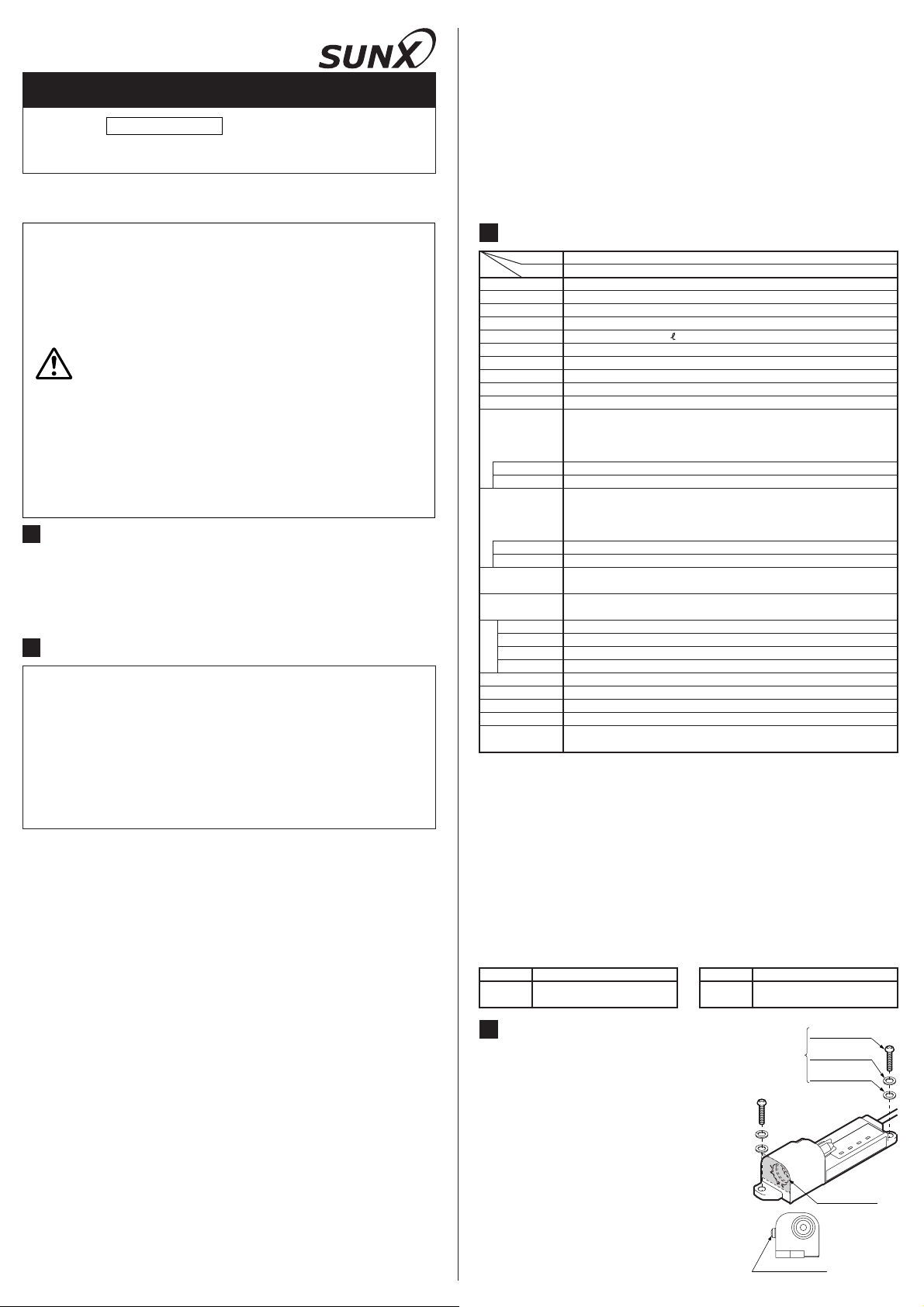
٨
When this product is mounted on a housing,
use M4 screws. (please arrange separately.)
The tightening torque should be 2N㨯m or less.
If more than 2 units are mounted closely, keep
٨
Description
IN: 100 to 120V AC, 50/60Hz, 40VA
OUT: 24V DC, 750mA
Model No.
ER-VANT
Description
Unit with Tungsten needle
(1 set)
M4 pan-head screw
Please arrange
separately
Spring lock-washer
Plain washer
5mm, or more, distance between them. Otherwise, the capability may be affected.
Make sure to ground this product. If the
٨
grounding is not proper, the charge removal
capability is reduced. (Direct earth or power
supply common earth)
If AC adopter is used, be sure to connect the
٨
ground terminal to the power supply common
Protective film
earth.
Ground terminal
٨٨This product cannot be used by its own. Be sure to fit the optional
nozzle for use of this product.
9#40+0)
٨ Since a protective film is affixed on the
For the details of the optional nozzle, refer to the instruction
manual enclosed with the nozzle.
ER-VS01
nozzle fitting part, be sure to remove it
before fitting the nozzle (optional). The
tightening torque should be 6N㨯m or less.
5
PIPING
٨
The outer diameter of the air-tube to fit to the air inlet portion of this product
Convex
part
Attachment
Resin tube
Shower nozzle (ER-VAS) (optional)
(Enclosed with nozzle)
Protective film
should be Ǿ6mm.
٨
Make sure that clean air (air containing no-water, no-oil and no dust) should
be supplied.
Since the pressure will drop when the air piping from the main pressure sup-
٨
ply is extended or pneumatic-components (e.g., needle valve, spin core, mini
filter) are added, keep an eye on the pressure supply to the ionizer making
sure it isn't in short supply. For the pneumatic- components, select those that
can accommodate the air supply flow rate.
6
I/O CIRCUIT DIAGRAMS
Terminal connecter No.
Color code
(Brown) +V
D
COM (+)
Tr1
Tr2
Sensor circuit
Ground
terminal
Internal circuit Users' circuit
Symbols... D: Reverse supply polarity protection diode
*1
Non-voltage contact or NPN open-collector transistor
Discharge halt input
Z
D1, ZD2:
Surge absorption zener diode
1,Tr2:
Tr
NPN
Low (0V): Discharge halt
High (Open): Discharge allowed (Operation starts)
Reset input
In the state that operation is stopped due to an error detection, open 0V of the
power supply from short-circuit state to cancel ERROR
٨ Connector pin arrangement
(Front view)
7
INPUT SIGNAL CONDITIONS
(Orange) Check output
Z
D1
(Black) Error output
Z
D2
(Pink) Discharge halt input
(Violet) Reset input
(Blue) 0V
COM (-)
output transistor
Terminal No.
Load
50mA max.
*1 *1
or
Ԙ
ԙ
Discharge halt input
Ԛ
ԛ
Ԝ
ԝ
Ԟ
ԟ
Load
50mA max.
㧗
㧙
Terminal Color code
0V
COM
Reset input
24V
COM
Check output
Error output
Blue
㧙
Pink
Violet
Brown
㧙
Orange
Black
٨ Conditions for the discharge halt input and the reset input are as follows.
Discharge halt input
0.5 sec.
DSC OFF
(Low input)
Note: Repeat control with 'DSC OFF' input
should be 1Hz or less.
Open
Low
or more
Reset input
RESET
(Start-up input)
Open
Low
10ms
or more
10ms
or more
24V DC
r10%
8
OPERATION MATRIX
Indicators ( 㧦Lights upޔ㧦OFF)
Discharge
Power
Green Green Orange
Normal
Check
Error
Discharge halt input
Reset input
'DSC OFF' input in the 'ERROR' state is invalid (since the 'ERROR' state is prioritized).
Notes: 1)
'RESET' input is enabled even when in the 'DSC OFF' input state, and 'DSC 'OFF' input
2)
remains unaffected by 'RESET' input.
'RESET' input in the 'ERROR' state resumes the 'ERROR' state unless the cause of the
3)
error has been eliminated.
9
MAINTENANCE
Check
(Maintained)(Maintained)
Error
Output
Check
N.O. N.C.Red
OFF
ON
OFF
OFF
(Maintained)
Error
ON
ON
OFF
ON
ON
٨٨Before checking the high-voltage part, be sure to turn off the
power supply, or you may get an electric shock.
WARNING
٨
Since the removal discharge effect will deteriorate if dirt is stuck to the tip of
Since the tip of the discharge needle is pointed, take sufficient
care when cleaning. There is a danger of injury.
the discharge needle, clean the discharge needle periodically.
٨
The maintenance required depends on the environment of use. As a reference, the maintenance should be done once in two weeks.
The discharge needle is a part having a product life time. It is recommended
٨
that the needle should be replaced, as a reference, after 10,000 hours in
use. When replacing it, replace the whole unit.
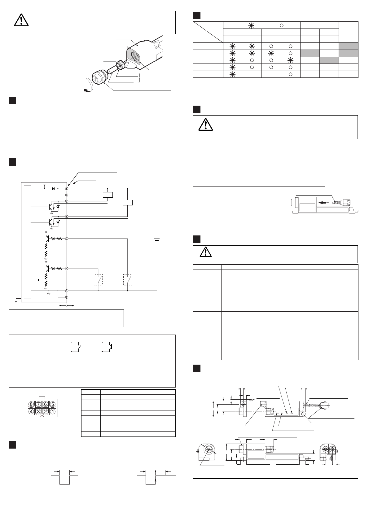
Procedure of cleaning and replacing the discharge needle
Ԙ
Confirm that the power supply is off.
ԙ
Unscrew the discharge needle counter-
Discharge needle unit
clockwise.
Remove the dirt on and around the dis-
Ԛ
charge needle with a cotton bud soaked in
alcohol.
After cleaning, screw the needle clockwise to fit. The tightening torque
ԛ
should be 0.3N㨯m or less.
10
TROUBLE SHOOTING
Make sure that the power supply is off while checking the highvoltage part. Otherwise, you may get an electric shock.
WARNING
Symptom Remedy
Check indicator
(orange)
lights up
Error indicator
(red) lights
up
Doesn't go back to
normal state by reset
11
DIMENSIONS (Unit: mm)
Make sure that the power voltage is within the tolerance as per specifications.
Check the tip of the discharge needle for chip and contamination, and make
sure that the discharge needle unit is mounted normally on the main body.
If the CHECK indicator (orange) lights up even after cleaning the
discharge needle, also check the nozzle part for contamination.
Make sure that the nozzle assembly (including the attachment and
the resin tube) is mounted properly.
Make sure that the air pressure is within the applicable range as per specifications.
Make sure that the power voltage is within the tolerance as per specifications.
Abnormal discharge is possible.
Turn off the power supply, check the tip of the discharge needle for chip and
contamination, and make sure that the discharge needle unit is mounted
normally on the main body. Also, check the inside of the nozzle for foreign
objects, and make sure that the nozzle is mounted and installed properly.
Make sure that the ground terminal is connected completely.
Make sure that the cause of the error has been eliminated.
٨ Mounting drawing with shower nozzle (optional)
Error indicator (Red)Check indicator (Orange)
2.8
5.5
11.7
27
16
PCC6-M8M manufactured by PISCO
Shower nozzle (ER-VAS) (optional)
28
4.3
18.8
Ǿ17.8
Airflow outlet
10 1089
SUNX Limited
100
Ground terminal
5.2
(M3)
Power indicator (Green)
31.712.3 14.3
Discharge indicator
(Green)
(4.5)4.5
Ǿ4.2 cable 0.5m (gray)
5559-08P manufactured
by Molex 5559-08P
2-Ǿ4.5 mounting holes
11.3
http://www.sunx.co.jp/
Head Office
2431-1 Ushiyama-cho, Kasugai-shi, Aichi, 486-0901, Japan
Phone: +81-(0)568-33-7211 FAX: +81-(0)568-33-2631
Overseas Sales Dept.
Phone: +81-(0)568-33-7861 FAX: +81-(0)568-33-8591
PRINTED IN JAPAN
Discharge
through
needle
ON
ON
OFF
OFF
(Allowed)
5.811.4
 Loading...