

Panasonic ER-Q Instruction Manual
INSTRUCTION MANUAL
Static Remover Ultra-compact Fan Ionizer
ER-Q
CMJE-ERQ No.0053-70V
Thank you very much for using Panasonic products. Please read this
Instruction Manual carefully and thoroughly for the correct and optimum use
of this product. Kindly keep this manual in a convenient place for quick
reference.
WARNING
Never use this product with a device for personnel protection.
In case of using devices for personnel protection, use products which meet laws
or standards, such as OSHA, ANSI or IEC etc., for personnel protection applicable
in each region or country.
Do not use this product in places where there may be a danger of fl ammable or
combustible items being present.
Clean the equipment regularly (discharge needles: about once every week, fi lter:
about once a month), otherwise optimum charge removal performance may not be
obtained and fi re or operating problems may occur.
If this product is used in an airtight room, ozone emitted from this product may be
detrimental. Therefore, in order for this product to be used in an airtight room, be
sure to keep the room ventilated.
Do not direct ionized air toward the face. Ozone may cause irritation to places
such as the nose and throat.
Since the tip of the discharge needle is sharp, take suffi cient care in handling the
discharge needle, or injuries may result.
Be sure to ground the frame ground (F.G.) terminal, otherwise electric charge
removal may not be reliable.
Take care not to let any foreign objects get into the fan air inlet, otherwise
accidents or operating problems may occur.
1 OUTLINE
This is a static charge remover which utilizes ion generation by means of corona
discharge.
It has a compact shape, so that it can be positioned either vertically or horizontally.
It is equipped with an automatic stop function which operates when the discharge
needle unit has been removed.
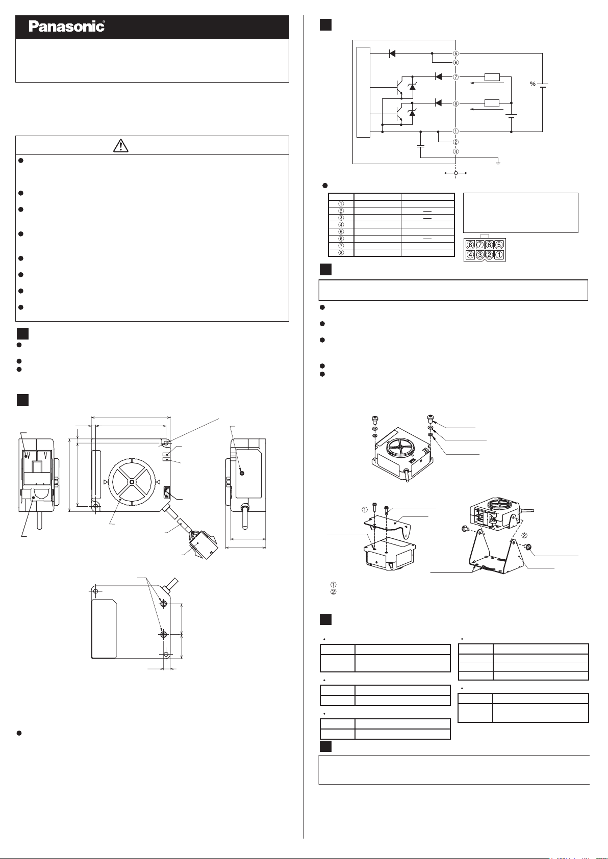
2 PART DESCRIPTION
Ion air outlet
Discharge needle unit
2-M3 screws (depth 10 mm) (Note 2)
Notes: 1) Fan speed control
This is set to MAX fan speed at the time of shipment from the factory.
Use a precision screwdriver (-) to adjust the fan speed.
2) Screw threads exclusive for SUNX mounting brackets. Do not use them in mounting with
other products.
When mounting this product directly to a case or such, fi x it with M3 screws using 2-Φ3.5
mounting holes.
Description of indicators
Discharge indicator (DSC) ... Lights during discharge
3.5
3.5
60
52
Alarm indicator (ALARM) ... Lights when discharge error or discharge checking
65
58
Filter cover
Φ3.7 mm cable
Connector 5559-08P
manufactured by MOLEX
5.5
2-Φ3.5 mm
mounting hole
Alarm indicator
(red)
Discharge indicator
(green)
Power switch
25.419.8
(when ions are being generated)
occurs, blinks when fan error occurs.
Fan speed control
(Note 1)
29
33
3 INPUT AND OUTPUT CIRCUIT DIAGRAM
D
1
Tr
1
ZD
Main circuit
Tr
2
1
ZD
2
Internal circuits
Connector pin layout diagram
Terminal name Lead wire color
Terminal no.
0 V
COM (-)
N.C. (Not used)
F.G.
24 V
COM(+)
Check output
Error output
Blue
Green
Brown
Orange
Black
4 MOUNTING
●
Be sure to turn off the power before carrying out angle adjustment for this
product, otherwise accidents or problems with operation may occur.
If installing this product directly to the enclosure, use M3 screws. (M3 screws
should be arranged separately.)
If using the ER-QMS1 (optional mounting bracket), use the screws provided with
the mounting bracket.
If using SUNX mounting bracket or screws other than the ER-QMS1, do not use
screws which are longer than 10 mm, otherwise they may cause damage to
internal parts when fastened.
Tightening torques are 0.5 N・m for M3 screws and 1.2 N・m or less for M4 screws.
If using several of these products alongside each other, leave a space of 50 mm
or more between each product, otherwise product performance may be adversely
affected.
[If installing this product directly to the enclosure]
[If using the
2-M3 screw
(depth 10 mm)
5
AC adapter
Model No. Details
ER-VAPS1
Replacement discharge needle unit
Model No. Details
ER-QANT
Replacement air filter
Model No. Details
ER-QFX5
6
●
●
●
ER-QMS1
Install bracket 1 to the main unit with the M3 screws.
Install bracket 2 to the main unit with the M4 sems screws, and then use the M4 screw
mounting holes to install to the enclosure.
* The M3 and M4 screws are included with the ER-QMS1.
(optional mounting bracket)]
M3 sems screw
Bracket 1
OPTIONS
IN: 100 to 240 V AC, 50/60 Hz, 40 VA
OUT: 24 V DC, 750 mA
Unit with tungsten needles
5-piece air filter set
CARE AND MAINTENANCE
Be sure to turn off the power before carrying out cleaning and maintenance.
The discharge needle has a sharp point, so be very careful when cleaning the
needle.
After long periods of use, dirt may adhere to the discharge needles, the area
around them and the filter. If these areas are not cleaned, charge removal
performance will drop and accidents or problems with operation may occur.
Therefore they should be periodically cleaned (discharge needles: about once
every week, fi lter: about once a month).
(Brown) +24 V
COM (+)
D
2
(Orange) Check output
D
3
(Black) Error output
(Blue) 0 V
M3 screw
Spring washer
Flat washer
M4 screw
mounting hole
ER-QMS1
Load
50 mA MAX
Load
50 mA MAX
COM(-)
(Green) F.G.
User’s circuits
D1: Power supply reverse connection
protection diode
D
, D3: Output protection diodes
2
ZD
, ZD2:
1
Tr1, Tr2: NPN output transistors
Front view
24 V DC
±10
30 V
DC MAX
Surge voltage absorption Zener diodes
M4 sems screw
Bracket 2
Cable with connectors
Model No. Details
ER-QCC2
ER-QCC5
Cable length 2 m
Cable length 5 m
Mounting bracket
Model No. Details
Mounting bracket for air
direction adjustment
●
The discharge needles are consumable parts. If the discharging performance is not
restored after the discharge needles have been cleaned, it is recommended that
you replace the whole discharge needle unit (option). It is recommended that you
replace the discharge needle unit after about 10,000 hours of operation.
[Cleaning and replacement procedure for discharge needle unit]
Follow the procedure given below to remove the discharge needle unit from the main unit.
Use a cotton swab or similar moistened in alcohol to clean the discharge needles
and the areas around them.
If the needles are particularly dirty, use a brush (such as a toothbrush) moistened
with alcohol to rub them clean, and then use a cotton swab to wipe them.
A commercially-available ultrasonic cleaner can also be used for cleaning. (Immerse
the discharge needle unit into the cleaning tank to clean them.)
Insert the tabs of the discharge needle unit into the two slots in the main unit, slide
the discharge needle unit sideways to install it to the main unit until a click is heard.
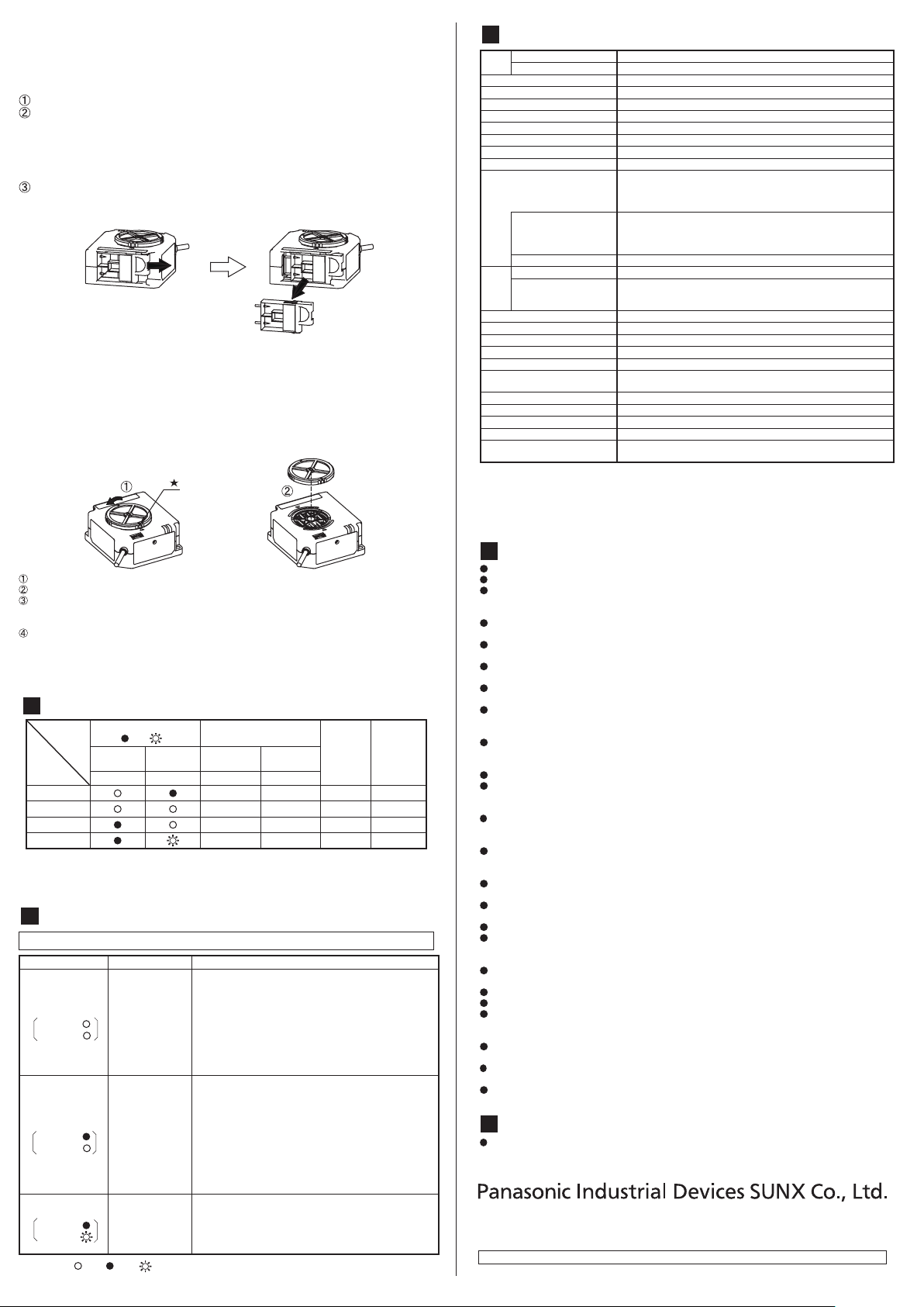
[Discharge needle unit removal procedure]
1
1 Hook your finger into the slot in the
discharge needle unit and slide the
unit in the direction shown in the
illustration until a click is heard.
2 After this, you can pull the
discharge needle unit toward you
to remove it.
* Do not touch the interior of the main unit when removing and installing the discharge
needle unit, otherwise accidents or problems with operation may occur.
* Do not apply any more force than is necessary when removing and installing the
discharge needle unit, otherwise the discharge needle unit may become damaged.
2
[Fan fi lter cleaning and replacement procedure]
Install and use a fi lter depending on the operating environment.
Turn the filter cover in the direction shown in the illustration to align the * marks.
Remove the filter cover and the filter from the ER-Q main unit.
Remove the filter from the filter cover, and remove any dust and dirt adhering to the filter. If the
filter is extremely dirty, wash it in water. If washing the filter in water, let it dry thoroughly before
using it again.
Install the filter and the filter cover to the ER-Q main unit.
* If the filter is used while it is still wet, accidents or problems with operation may occur.
* If the filter cannot be cleaned, replace it.
* Be careful not to let any foreign objects get inside the main unit when removing and installing the
filter.
7 OPERATION MATRIX
Indicator
(O: Lit, : Off, : Blinking)
Discharge
(DSC)
Normal OFFONONON
Discharge check
Discharge error
Fan error
Green RedNormal open
Alarm
(ALARM)
* Once an error has been detected, the error status will be maintained until the power
is turned off and back on again.
* Eliminate the cause of the error before turning the power back on again.
* If the cause of the error has not been eliminated, the error will occur again.
Output
Check Error
Normal closed
ON ON ON ON
OFFOFF OFF OFF
OFFOFF OFF OFF
Discharge
operation
operation
Fan
8 TROUBLESHOOTING
●
Be sure to turn off the power before checking the discharge unit or the fan unit.
Problem Probable cause Remedy
Dirty discharge
Discharge check
Discharge
Alarm
Discharge error
Discharge
Alarm
Fan error
Discharge
Alarm
* Indicators (
needle
Wear
Condensation
F.G. not
connected
Foreign object
obstruction
Condensation
F.G. not
connected
Fan intake
covered
Filter blocked
Foreign object
obstruction
: Lit, : Off, : Blinking)
Check that the power supply voltage is within theusable
・
range.
Turn off the power and check that the tips of thedischarge
・
needles are not worn or dirty and that the discharge
needle unit is correctly installed to the main unit.
If the alarm indicator remains lit even after the discharge
・
needles have been cleaned, check for any dirt around
the discharge needles also.
Check that the F.G. terminal is securely connected to the round.
・
Check that the power supply voltage is within the usable
・
range.
There may be an abnormal discharge. Turn off the
・
power and check that the discharge needles are not
dirty or broken and that the discharge needle unit is
correctly installed to the main unit.
If the alarm indicator remains lit even after the discharge
・
needles have been cleaned, check for any dirt and
foreign objects around the discharge needles also.
Check that the F.G. terminal is securely connected to the ground.
・
Turn off the power and check if the fi lter is blocked.
・
Check if there are any foreign objects inside the product.
・
9 SPECIFICATIONS
Type Fan type ionizer
Item
Model No. ER-Q
Charge removal time 1.5 sec. approx. (Note 1)
Ion balance ±10 V or less (Note 1)
Power supply voltage 24 V DC ±10 %
Power consumption 200 mA or less
Discharge method High-frequency AC method
Discharge output voltage ±2 kV approx.
Max. fan speed 6.4 m/s (Note 1)
Max. fan volume 0.2 m
Output
(CHECK, ALARM)
Output operation
Short-circuit protection Incorporated
DSC Green LED (Lights up during normal discharge)
ALARM
Indicators
Ozone generation amount 0.02 ppm or less (Note 1)
Pollution leve
Ambient temperature
Ambient humidity
Operating altitude 2,000m or less (Note 3)
Vibration resistance
Over-voltage category I
Material Enclosure: PBT Discharge needle: Tungsten
Grounding methodC (capacitor) grounding
Weight 110g approx. (main unit only)
Accessories
Notes: 1) Representative value at 100 mm from directly in front of fan outlet, maximum fan speed
10
This product has been developed / produced for industrial use only.
Do not use this product for any purpose other than charge removal and dust removal.
Do not use t his product in enviroments which are outside the specification range,
otherwise operating problems or damage may occur. In addition, the operating life of the
product may become signifi cantly reduced.
Never disassemble, repair or m odify this product, otherwise operating problems or
accidents may occur.
Do not dispose of this product by burning it, otherwise it may explode or toxic fumes may
be generated.
This product generates ozone, so be sure to provide adequate ventilation if using it in a
confi ned space.
Do not run the wires together with high-voltage lines or power lines or put them in the
same raceway. This can cause malfunction due to induction.
Be sure to turn off the air and the power supply before carrying out any cable connection
or inspection work. If this is not done, operating problems, damage or electric shocks
may occur.
After connecting the cables, check that the connections are correct before turning on
the power. If the cables are connected incorrectly, operating problems or accidents may
occur.
Verify that the supply voltage variation is within the rating.
It takes approximately 2 seconds after the power is turned on before the fan operation
stabilizes. To ensure proper charge removal performance, do not use the product until
suffi cient time has elapsed.
Do not turn the power back on immediately after it has been turned off, otherwise operating
problems or accidents may o ccur. In addition, the operating life of t he product may become
signifi cantly reduced. Wait at least 2 seconds before turning the power back on again.
When using as a CSA and UL compliant product, use a CLASS 2 CSA/UL certified
power supply, or a CSA/UL certifi ed power supply that has been evaluated as a Limited
Power Source as specifi ed in CAN/CSA-C22.2NO.60950-1/UL60950-1.
Do not use any cables which have any damage (such as splitting or cracking), otherwise
operating problems or accidents may occur.
Avoid using the product in places where there are high levels of steam or dust in the air
or where it might be directly exposed to water, oil or welding spatter.
Avoid use at an elevation higher than 2000m, and outdoor use.
Do not touch the discharge needle with hard objects such as tools. If the discharge
needle becomes broken, it will not provide suffi cient charge removal performance, and
moreover operating problems or accidents may occur.
Avoid using the product while the fi lter is blocked, otherwise accidents or problems with
operation may occur.
Clean and replace the fi lter at periodic intervals.
Always be sure to turn off the power before replacing the fi lter.
Secure the main unit properly when setting up. If the main unit is not correctly secured
or if it is subjected to intermittent vibrations or impacts, accidents or problems with
operation may occur.
Do not place any objects which may obstruct air fl ow within 20 mm the front of the fan air
intake, otherwise accidents or problems with operation may occur.
Use cables with a cross-section of 0.15 mm2 or more and a length of less than
30 m. Furthermore, keep the cables as short as possible to avoid the possibility of interference.
If this product ceases functioning or is no longer required, dispose of it according to
appropriate local waste disposal regulations.
11
This product complies with CSA and UL standards, and has been certifi ed by TUV SUD.
http://panasonic.net/id/pidsx/global
Overseas Sales Division (Head Offi ce)
2431-1 Ushiyama-cho, Kasugai-shi, Aichi, 486-0901, Japan
Phone: +81-568-33-7861 FAX: +81-568-33-8591
About our sale network, please visit our website.
PRINTED IN JAPAN© Panasonic Industrial Devices SUNX Co., Ltd. 2016
l2
with fi lter not installed.
2) Discharge check: Drop in discharging status detected.
Discharge error: Abnormal discharge detected.
Fan error: Fan operating problem detected.
3) Do not use or store the device in an environment where the air pressure is higher than the
atmospheric pressure at an altitude of 0 meters.
CAUTIONS
CSA/UL compliant product
NPN transistor/open collector
• Max. sink current: 50 mA
Applied voltage: 30 V DC or less (between output terminal and 0 V)
•
• Residual voltage: 1 V or less (at input current of 50 mA)
Check: On when discharge check (Note 2) detected
Off at all other times
Error: Off when discharge error or fan error (Note 2) detected
On at all other times
Red LED (Lights up during discharge checking and when
discharge error (Note 1) detected, blinks when fan error (Note 1)
detected)
0 to + 50°C (No dew condensation) / Storage temperature: -10 to + 65°C
35 to 65% RH (No dew condensation) / Storage temperature: 35 to 65% RH
10 to 150 Hz frequency, 0.75 mm amplitude in X, Y and Z
directions for two hours each
Wiring connector: 1 set
[Manufactured by MOLEX: Housing (5557-08P), Terminal (5556T)
3
/min
]
 Loading...