


PR-SC5530
PR-SC5530
AV CONTROLLER
Basic Manual
Advanced Manual found here
http://www.onkyo.com/manual/prsc5530/adv/en.html
E
n
Before Start
About the Basic Manual
This unit works as an AV controller when connected with a
separately sold multichannel power amplifier.
The Basic Manual leads you through the initial procedure
to enjoy various sources with the AV controller, describing
how to make settings and connections, and how to use
popular functions. Besides, there is another part of the
manual called Advanced Manual to inform you with more
detailed information, which we have decided to publish on
the web from the ecological point of view.
Advanced Manual
Advanced Manual is always updated with the latest
information and its user friendly interface, which does not
matter whether you access from PC or Smartphone, helps
you to understand more deeply about this unit. Advanced
Manual is consisted of the following chapters.
r Details on AM/FM reception
r Playing Music Files on a USB Storage Device
r Listening to Internet Radio
r Playing Music with DLNA
r Playing Music Files in a Shared Folder
r Operating Music Files with the Remote Controller
r Listening Mode
r Advanced Settings
r Operating Other Components with the Remote Controller
r Advanced Connection
r Connecting and Operating Onkyo RI Components
r Control function between the unit and external
component
r Firmware Update
r Troubleshooting
r Reference Information
Advanced Manual found here
http://www.onkyo.com/manual/prsc5530/adv/en.html
Features
r Supports playback in Dolby Atmos format which provides
360-degree placement and movement of sounds
including overhead sound
r Dolby Surround listening mode expands 2 ch, 5.1 ch or
7.1 ch source to available speaker configurations
r THX Ultra2 Plus certified
r
Incorporates Qdeo™ technology for HDMI video
upscaling
r All HDMI jacks support displays of 4K resolution at 60 Hz
r Supports the HDMI Through function which allows
transmission from playback devices to the TV in standby
state
r Supports HDCP2.2, a strict copy-protection for providing
high quality content (HDMI IN3/OUT MAIN only)
r Supports ARC (Audio Return Channel)
r Supports USB storage playback
r Supports variety of network functions such as Internet
Radio, DLNA, etc.
r Supports Wi-Fi, Bluetooth and MHL-enabled mobile
device
r Bi-Amping capability
r
A/V Sync Function to correct deviation of audio and video
r Multi-zone function which allows you to play a different
source in another room from the main room (Video can
also be played in Zone 2)
r 32 bit DSP (Digital Signal Processor) with excellent
calculation performance
r Music Optimizer™ for Compressed Digital Music files
r Phase Matching Bass System
r Automatic speaker setup available using supplied
calibrated microphone (AccuEQ Room Calibration)
r Supports playback of MP3, FLAC, WAV, Ogg Vorbis,
Apple Lossless, DSD via network and USB storage
device (the supported formats will differ depending on
the use environment)
r ISF (Imaging Science Foundation) Video Calibration
r XLR balanced jack (11.2 channel output, stereo input)
minimizing noises in long distance transmission
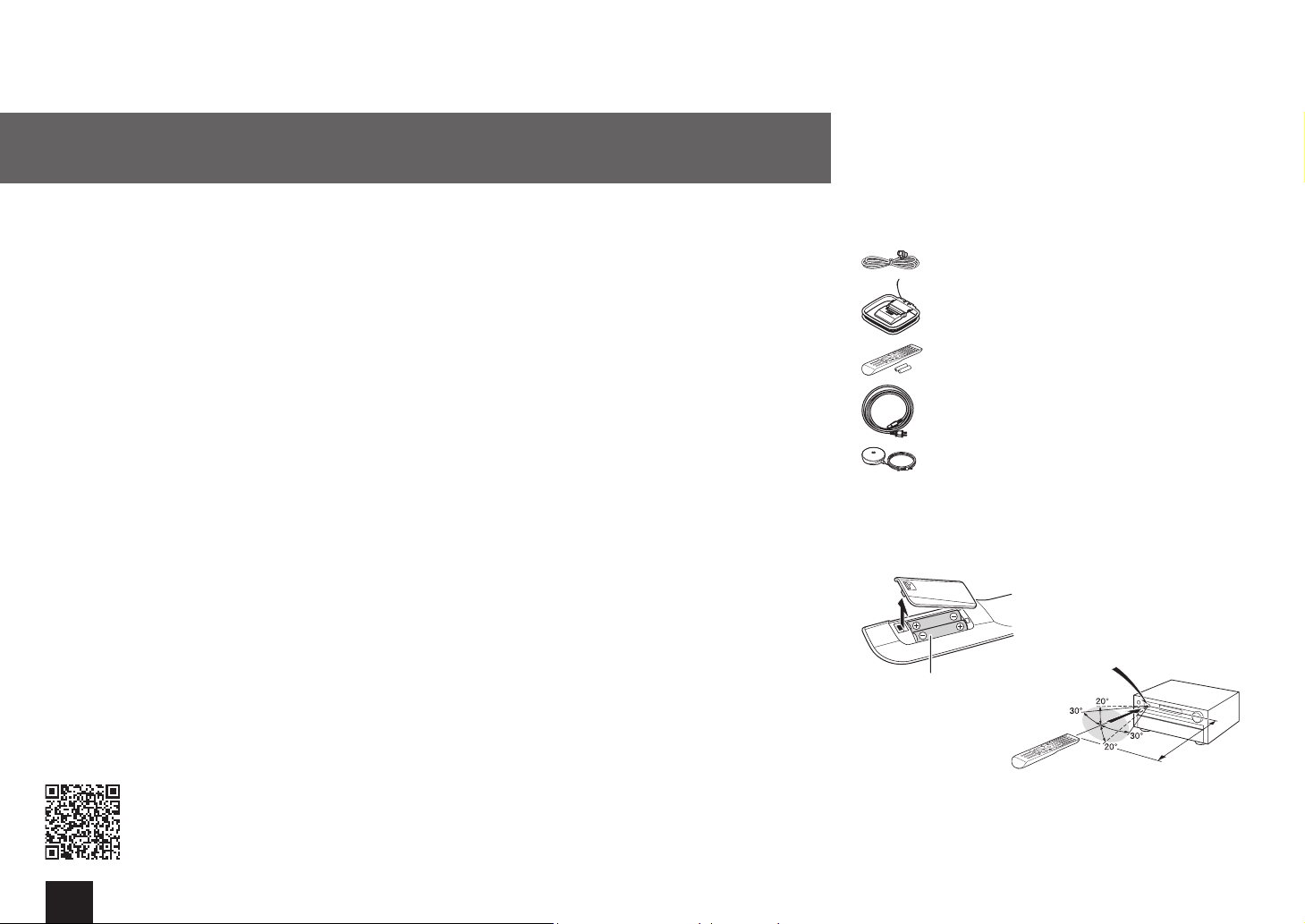
Supplied Accessories
Indoor FM antenna --- (1)
AM loop antenna --- (1)
Remote controller (RC-884M) --- (1)
Batteries (AA/R6) --- (2)
Power cord --- (1)
Speaker setup microphone --- (1)
¼
The number in parenthesis indicates the quantity. On packaging, the letter
at the end of the product name indicates the color.
How to use the remote controller
Remote control sensor
Batteries (AA/R6)
¼
If you do not use the remote controller for a long time, remove the
batteries to prevent leakage.
¼
Note that keeping consumed batteries inside may cause corrosion
resulting in damage of the remote controller.
The unit
About 16 ft
(5 m)
2
Step 1:
Personal computer
Connections
HDMI
OUT
HDM
TV
I
IN
HDMI cable
HDMI
OUT
Game console
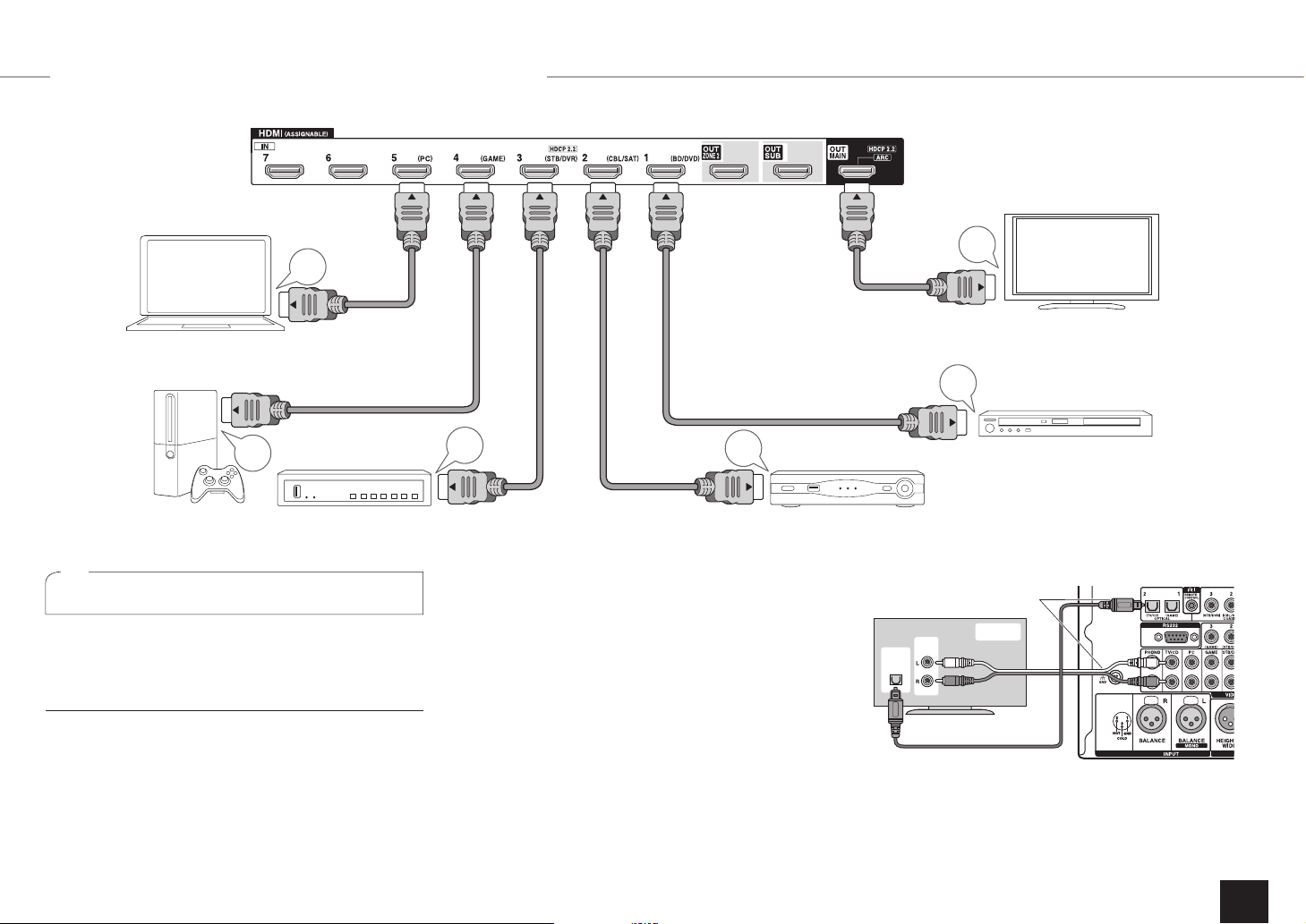
Connecting the TV and players
1
Set-top box/Digital
video recorder, etc.
Important: The power cord must be connected only after all
other connections are completed.
HDMI cable connection
The unit has many HDMI jacks on its rear panel and each
of them corresponds to an input selector button of the same
name on the front panel. For example, a Blu-ray Disc player
will be connected to the IN 1 jack and the BD/DVD button
on the front panel will be used to listen to the playback
sound (if the player is CEC compliant, input will be switched
automatically). If you add another Blu-ray Disc player, you
can use any other jack than IN 1. It is possible to change
assignment of the input jacks and input selector buttons.
HDMI
OUT
HDMI
OUT
Satellite/Cable
set-top box, etc.
For how to make settings, see the Advanced Manual.
To connect the TV and the unit, connect the HDMI OUT
MAIN jack of the unit and the HDMI IN jack of the TV
using an HDMI cable. With this connection, it becomes
possible to display the setting screen of the unit on the
TV or transmit video/audio signals from the player to the
TV. On an ARC (Audio Return Channel) compatible TV,
simply making this connection enables transmission of TV
sound to a power amplifier connected with this unit. If your
TV does not support ARC, you need, in addition to the
HDMI OUT MAIN jack connection, a digital optical cable
connection between the digital audio out optical jack of
the TV and the DIGITAL IN OPTICAL jack of the unit or an
analog audio cable connection between the audio output
jack of the TV and the TV/CD analog audio input jack of the
unit.
To use the ARC function, connect to the ARC
compatible HDMI jack of the TV and make an
appropriate setting on the unit. See "2nd Step :
Source Connection" of "Step 2: Setting Up".
HDMI
OUT
Blu-ray Disc/DVD player
z
Audio connection with a TV not supporting ARC
¼
Select an appropriate
connection for your TV.
TV
PUSHPUSH
DIGITAL
OPTICAL
OUT
AUDIO
OUT
Another TV can be connected to the HDMI OUT
SUB jack. In this case, press MONITOR OUT on the main
unit several times to display "SUB" or "MAIN+SUB" and
select the output method. You can also enjoy using Zone
function with the HDMI OUT ZONE 2 jack. For details, see
3
the section 6 "Using the multi-zone function" of "Step 3:
PUSHPUSH
Playing Back".
The unit supports the HDMI Through function that allows
transmission from players to the TV even if the unit is in
standby. You have to modify the settings to enable the
input selection link with CEC compliant device, connection
with ARC compatible TV, and HDMI Through function. See
the section 2 "2nd Step : Source Connection" of "Step 2:
Setting Up".
r To enjoy HDCP2.2 protected video, connect the player to
the IN3 jack and the TV to the HDMI OUT MAIN jack of
the unit. Your player and TV need to support HDCP2.2.
r To play 4K or 1080p video, use the high speed HDMI
cable.
r It is possible to send video and audio of an MHL-enabled
mobile device by connecting the MHL-enabled mobile
device to the AUX INPUT HDMI/MHL jacks on the front
panel.
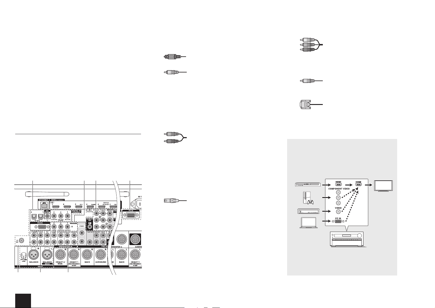
Connecting Components without HDMI
If your AV component does not have HDMI jack, use an
available jack of your component for cable connection with
this unit. Just as the HDMI jacks, other jacks on this unit
have a preassigned input selector button on the front panel.
See the name of the input selector button shown with the
jack when connecting the device.
1
6235 7
Audio signal connection
Digital connection: Use a digital optical cable
1
(OPTICAL) or digital coaxial cable (COAXIAL) for
connection with a player.
Digital optical cable (OPTICAL)
¼
As the digital in optical jack of the unit has a
cover, push in the cable against the cover as it is
turned inside.
Digital coaxial cable (COAXIAL)
Analog connection: Use an analog audio cable for
2
connection with a player.
To enjoy multi-zone playback of audio of a CD player
or such other player without HDMI output jack, you
need to use the analog audio cable to connect the
corresponding jacks of the player and this unit. For
details on the multi-zone function, see the section 6
"Using the multi-zone function" of "Step 3: Playing
Back".
Analog audio (RCA) cable
Balanced connection: Use an XLR balanced cable for
3
connection with a player. An XLR balanced cable, which
is less affected by noise when extended over a long
distance, is suitable for long-distance transmission.
¼
Refer to the position indication for connection beside the BALANCE
INPUT jack.
¼
You have to make an appropriate setting to play audio of the device
connected to this jack. For more information, see the Advanced
Manual.
Step 1:
Use a component video cable to connect a TV
5
Connections
with component video input jacks and a player with
component video output jacks.
Component video cable
¼
Its transmitted video has higher quality than that
of composite video cable.
Use a composite video cable to connect a TV with
6
composite video input jack or a player with composite
video output jack.
Composite video cable
Use an analog RGB cable to connect the unit with a PC.
7
Analog RGB cable
¼
Video signals from the PC connected with the PC IN port will be
output only to a TV connected with the HDMI OUT MAIN/SUB/
ZONE2 jack.
Video signals input to the composite video input jack,
the COMPONENT VIDEO input jack, or the PC IN
port will be upconverted to HDMI signals and then
output from the HDMI output jack. Note that it is
not possible to convert digital audio input signals to
analog or vice versa.
4
XLR balanced cable
Connection with turntable: If it uses an MM type
4
cartridge and does not have a built-in audio equalizer,
connect it to the 4 PHONO jack. If the connected
turntable has a built-in audio equalizer, connect it to the
TV/CD jack.
2
¼
If it uses an MC type cartridge, install an audio equalizer compatible
with MC type cartridge between the unit and the turntable by
connecting it to the 2 TV/CD jack. For details, refer to the turntable's
instruction manual.
¼
If the turntable has a ground wire, connect it to the GND terminal of
this unit. If connecting the ground wire increases noise, disconnect it.
Video signal connection
The unit has a video upconversion function. For details, see
the next section.
¼
If multiple video signal inputs are put into one input
system, the output will be made in the order of HDMI,
component video, and composite video.
AV Controller
4
Connecting speakers
cd
2
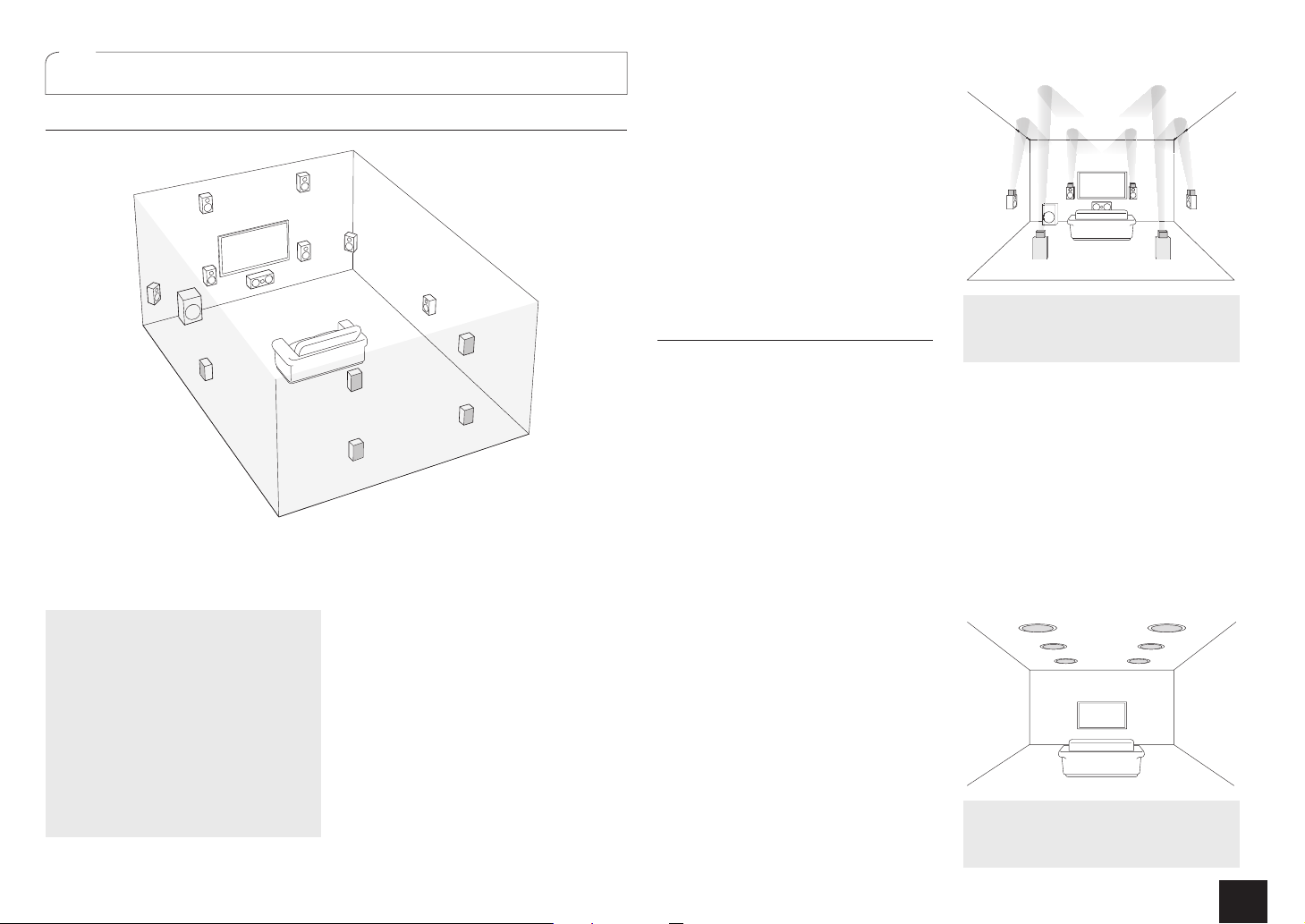
Speaker layout
9
I
To enjoy the Dolby Atmos listening
mode, Height 1 speakers, Surround back
speakers or Wide speakers need to be
installed.
Front speakers
" #
Center speaker
$
Surround speakers
% &
Subwoofer
'
Surround back speakers
7 8
Height 1 speakers (Front High)
9 F
Height 2 speakers (Rear High)
G H
Wide speakers
I J
rGH and IJ share the same speaker
terminals. Select either of the groups.
r To use the multi-zone function, see the
section 6 "Using the multi-zone function"
of "Step 3: Playing Back".
"
'
%
F
#
$
J
G
7
5.1 ch: Connect the speakers
"#$%&'
front stereo sound. $outputs center
sounds such as dialogs and vocals.
create back sound field. ' reproduces
bass sounds and creates rich sound field.
Up to 4 subwoofers can be connected to
the unit.
Surround back speakers: Placing
URGCMGTUCNNQYURNC[DCEMKP|EJ
78
configuration that improves sense of
envelopment created by back sound field.
It also improves seamlessness of back
sounds and provides more natural sound
experiences in the sound field.
Height speakers 1 and 2: Placing 9F or
speakers produce surround effects on
GH
a height plane.
r To enjoy the Dolby Atmos listening
mode, Height 1 speakers or Surround
&
H
8
to the unit. "# output
%&
back speakers need to be installed.
r Although Height 1 speakers can
enhance surround effects, we
recommend you to add Height 2
speakers in order to ensure full effects.
r Install Height speakers such as Front
High and Rear High speakers on the
upper part of the front or rear wall. There
are other types of Height speakers.
Wide speakers: Placing IJ speakers
makes the front sound field even wider. It
also give smoother transitions between
front and back surround sounds.
Height speakers arrangements
(Dolby Atmos)
There are several types of height speakers
other than those mentioned in the previous
section. See the next section "Combination
patterns for Height speakers 1 and 2" and
select the combination pattern from those
specified for Height speakers 1 and Height
speakers 2.
r This unit performs optimal sound
field processing for the type of Height
speakers 1 and 2 which is registered
in initial settings (with setup wizard)
according to an actual speaker layout.
Note that the optimal effect cannot be
achieved if you place height speakers in
a combination pattern other than those
specified.
r Dolby recommends to place the
speakers as described in “Installing
speakers in ceiling” to obtain the best
Dolby Atmos effect.
Step 1:
Connections
Using Dolby Enabled Speakers
ab
ef
Dolby Enabled Speaker (Front)
a b
Dolby Enabled Speaker (Surround)
c d
Dolby Enabled Speaker (Back)
e f
A Dolby Enabled Speaker is specially designed
to be used as a Height speaker. There are two
types of Dolby Enabled Speakers, the one is to
be placed on the top board of other speakers
such as front speakers and surround speakers,
and the other is integrated type with the normal
speakers. Dolby Enabled Speakers placed
with their diaphragms facing toward the ceiling
create higher effect in the Dolby Atmos and
Dolby Surround listening modes by providing
sounds echoing off the ceiling.
Installing speakers in ceiling
kl
ij
gh
Top Front
g h
Top Middle
i j
Top Rear
k l
5
Ceiling speakers, etc. are used for maximizing effects in Dolby
P
H
Atmos or Dolby Surround listening mode. Install Top Front
speakers midway between the position just above the listening
position and the position just above the front speakers. Install Top
Middle speakers just above the listening position. Install Top Rear
speakers midway between the position just above the listening
position and the position just above the surround back speakers.
Step 1:
PUSHPUSH
USHPUS
Connections
Combination patterns for Height speakers 1 and 2
Dolby recommends the following combination pattern
to obtain the best effect of Dolby Atmos and Dolby
Surround listening modes.
r Pair 1: Top Middle
r Pair 2: Top Front / Top Rear
The following are the patterns of Height speakers 2 that
can be selected according to the type of Height speakers 1.
Height speakers1: Front High
Height speakers2: Not Use/Top Middle/Rear High/Dolby
Enabled Speaker (Surround)/Dolby Enabled Speaker (Back)
Height speakers1: Top Front
Height speakers2: Not Use/Top Rear
Height speakers1: Top Middle
Height speakers 2 cannot be used.
Height speakers1:
Height speakers2: Not Use/Dolby Enabled Speaker
(Surround)/Dolby Enabled Speaker (Back)
Height speakers1: Dolby Enabled Speaker (Surround)
Height speakers 2 cannot be used.
Height speakers1:
Height speakers 2 cannot be used.
r When front speakers are bi-amp connected, you can select
a pattern for Height speakers 2 from the following options.
Not Use/Front High/Top Front/Top Middle/Dolby Enabled
Speaker (Front)/Dolby Enabled Speaker (Surround)/Dolby
Enabled Speaker (Back)
Dolby Enabled Speaker (Front)
Dolby Enabled Speaker (Back)
H
Height2 R/
J
Wide R
F
Height1 R
8
Surround
back R
&
Surround R
#
Front R
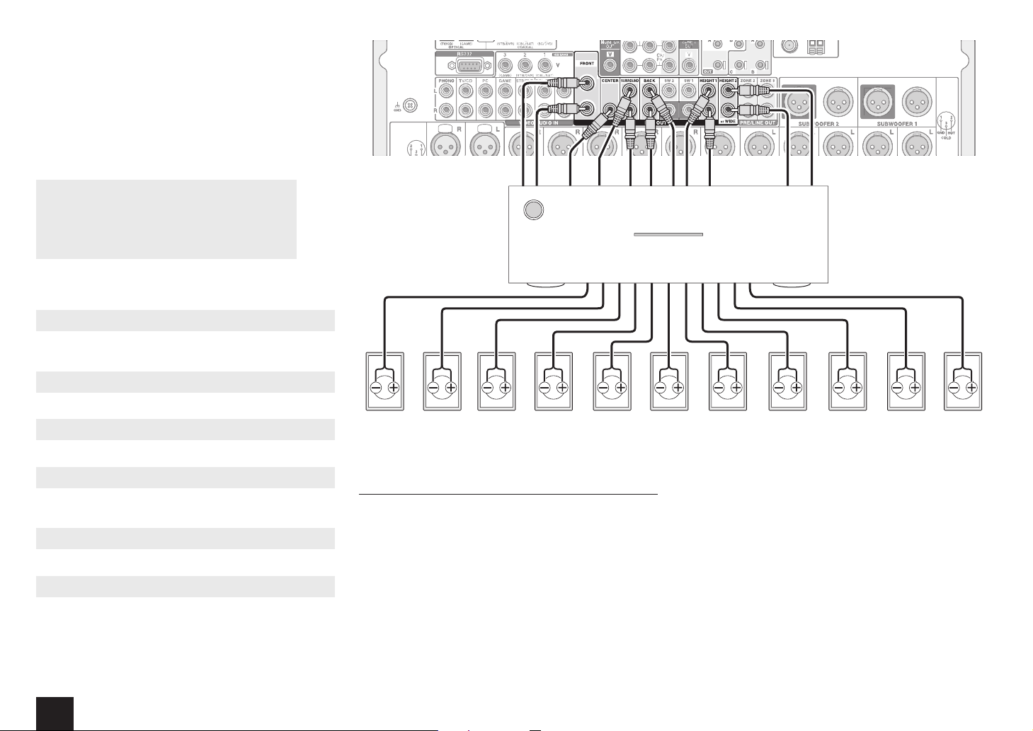
Notes for speaker connection
This unit works as an AV controller when connected with
a separately sold multichannel power amplifier. Connect
a power amplifier to the PRE OUT RCA jack or PRE
OUT XLR jack of the unit and then connect speakers to
the speaker terminals of the power amplifier. For how to
connect the power amplifier with speakers, refer to the
instruction manual of the multichannel power amplifier.
r Set the crossover frequency, speaker distance and other
speaker settings on this unit.
RCA cable
$
Center
"
Front L
Connecting the multichannel power amplifier
%
Surround L
7
Surround
back L
9
Height1 L
to the PRE OUT RCA jack
Connect the multichannel power amplifier to the PRE OUT
RCA jack. Connect the unit and power amplifier with an
RCA cable.
G
Height2 L/
I
Wide L
6
H
Height2 R/
J
Wide R
F
Height1 R
PUSHPUSH PUSHPUSH
8
Surround
back R
&
Surround R
#
Front R
$
Center
"
Front L
%
Surround L
XLR balanced cable
7
Surround
back L
9
Height1 L
G
Height2 L/
I
Wide L
Step 1:
Connections
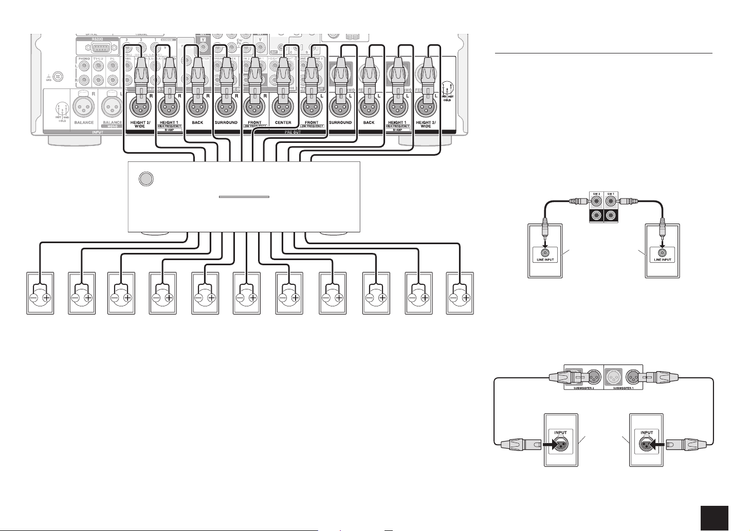
Connecting a subwoofer with built-in power
amplifier
The maximum four units of two systems of subwoofer
with built-in power amplifier can be connected to this unit.
Use the SW1/2 PRE OUT RCA jack or SUBWOOFER 1/2
PRE OUT XLR jack according to the input jack of your
subwoofer. You can also set the level and distance of the
connected subwoofer.
r If your subwoofer does not have built-in power amplifier,
you can connect a power amplifier between the unit and
the subwoofer.
Connection to the PRE OUT RCA jack
Connect the RCA input jack of your subwoofer and the
SW1/2 PRE OUT RCA jack of the unit with an RCA cable.
Subwoofer with built-in
power amplifier
r If you use one subwoofer system only, connect it to the
SW1 PRE OUT RCA jack.
Connection to the PRE OUT XLR jack
Connect the XLR balanced input jack of your subwoofer and
the SUBWOOFER 1/2 PRE OUT XLR jack of the unit with
an XLR balanced cable.
Connecting the multichannel power amplifier
to the PRE OUT XLR jack
Connect the multichannel power amplifier to the PRE OUT
XLR jack. Connect the unit and power amplifier with an
XLR balanced cable.
r Refer to the position indication for connection on the right
of the PRE OUT XLR jack.
Subwoofer
with builtin power
amplifier
r If you use one subwoofer system only, connect it to the
SUBWOOFER 1 PRE OUT XLR jack.
7
Step 1:
Connections
Other connections
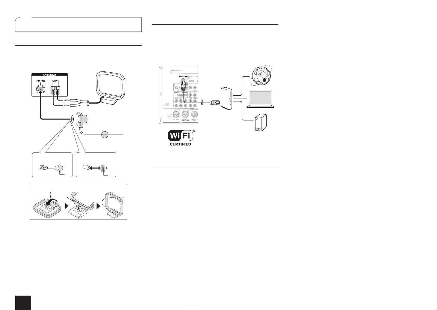
3
AM/FM antenna connections
Connect the antennas to listen to AM/FM broadcast. When
listening to the broadcast for the first time, adjust the
antenna position and orientation to get the best reception.
AM loop antenna
(supplied)
Indoor FM antenna
(supplied)
Fix with a tack on
the wall.
(North American
model)
Assemble the AM loop antenna (supplied).
(European and Asian
models)
Network connection
You can enjoy Internet radio and DLNA by connecting the
unit to LAN. The unit can be connected to the router with
an Ethernet cable or to the wireless LAN router with WiFi connection. In case of wired connection, connect the
Ethernet cable to the Ethernet port. See "4th Step: Network
Connection" of "Step 2: Setting Up".
Internet radio
Router
PC
NAS
Headphones connection
%QPPGEVUVGTGQJGCFRJQPGUYKVJCUVCPFCTFRNWI|KPEJ
or ø 6.3 mm) to the PHONES jack on the front panel.
Sound from the speakers will be off while you are using the
headphones.
r If you selected any other listening mode than Pure Audio,
Stereo, Mono and Direct, connecting headphones will
switch the listening mode to Stereo.
8
 Loading...