


 Loading...
TM
User’s Guide
Guide
Shop online at omega.com
e-mail: info@omega.com For latest product manuals: omega.com/en-us/pdf-manuals
FDT-25W
Wall Mounter Ultrasonic Flowmeter

omega.com info@omega.com
Servicing North America:
U.S.A. Omega Engineering, Inc.
Headquarters: 800 Connecticut Ave. Suite 5N01, Norwalk, CT 06854 Toll-Free: 1-800-826-6342 (USA & Canada only) Customer Service: 1-800-622-2378 (USA & Canada only)
Engineering Service: 1-800-872-9436 (USA & Canada only)
Tel: (203) 359-1660 Fax: (203) 359-7700 e-mail: info@omega.com
The information contained in this document is believed to be correct, but OMEGA accepts no liability for any errors it contains, and reserves the right to alter specifications without notice.

FDT-25W Wall Mounter Ultrasonic Flowmeter
Wall Mounter Ultrasonic Flow Meter User Manual
|
Contents |
|
1. Introduction........................................................................................................................................................... |
3 |
|
1.1 |
Preface........................................................................................................................................................ |
3 |
1.2 |
Features..................................................................................................................................................... |
3 |
1.3 |
Flow measurement principle................................................................................................................... |
3 |
1.4 |
Optional transducer.................................................................................................................................. |
4 |
1.5 |
Typical application.................................................................................................................................... |
4 |
1.6 |
Product Identification................................................................................................................................ |
5 |
1.7 |
Specifications............................................................................................................................................. |
5 |
2. Installation and Measurement........................................................................................................................... |
6 |
|
2.1 |
Dimension.................................................................................................................................................. |
6 |
2.2 |
Wiring.......................................................................................................................................................... |
7 |
2.3 |
Keypad........................................................................................................................................................ |
7 |
2.4 Menu Windows.......................................................................................................................................... |
8 |
|
2.5 |
Steps to Configure the Parameters....................................................................................................... |
9 |
2.6 |
Transducers Mounting Allocation......................................................................................................... |
10 |
2.7 |
Transducers Installation......................................................................................................................... |
11 |
2.8 |
Installation Checkup............................................................................................................................... |
14 |
3. Menu Window Details....................................................................................................................................... |
15 |
|
3.1 |
Menu Windows Arrangement................................................................................................................ |
15 |
3.2 |
Menu Window Details............................................................................................................................ |
16 |
4. How To................................................................................................................................................................ |
25 |
|
4.1 |
How to judge if the instrument works properly................................................................................... |
25 |
4.2 |
How to judge the liquid flowing direction............................................................................................ |
25 |
4.3 |
How to change between units systems.............................................................................................. |
25 |
4.4 |
How to select a required flow rate unit................................................................................................ |
25 |
4.5 |
How to use the totalizer multiplier........................................................................................................ |
26 |
4.6 |
How to open or shut the totalizers....................................................................................................... |
26 |
4.7 |
How to reset the totalizers..................................................................................................................... |
26 |
4.8 |
How to restore the flow meter with default setups............................................................................ |
26 |
4.9 |
How to use the damper.......................................................................................................................... |
26 |
4.10 How to use the zero-cutoff function................................................................................................... |
26 |
|
4.11 How to setup a zero point.................................................................................................................... |
27 |
|
4.12 How to get a scale factor for calibration........................................................................................... |
27 |
|
4.13 How to use the system locker............................................................................................................ |
27 |
|
4.14 How to use 4-20mA current loop output........................................................................................... |
27 |
|
4.15 How to use the Frequency Output..................................................................................................... |
28 |
|
4.16 How to use the Totalizer Pulse Output.............................................................................................. |
28 |
|
4.17 How to produce an alarm signal........................................................................................................ |
29 |
|
4.18 How to use the built-in Buzzer............................................................................................................ |
30 |
|
1

FDT-25W Wall Mounter Ultrasonic Flowmeter
4.19 |
How to use the OCT output................................................................................................................ |
30 |
4.20 |
How to modify the built-in calendar................................................................................................... |
30 |
4.21 |
How to view the Date Totalizers......................................................................................................... |
30 |
4.22 |
How to use the Working Timer........................................................................................................... |
30 |
4.23 |
How to use the manual totalizer......................................................................................................... |
30 |
4.24 |
How to know how long the battery will last...................................................................................... |
31 |
4.25 |
How to check the ESN and other minor details............................................................................... |
31 |
4.26 |
How to use the data logger for scheduled output........................................................................... |
31 |
4.27 |
How to output analogue voltage signal............................................................................................. |
31 |
4.28 |
How to adjust the LCD display........................................................................................................... |
31 |
4.29 |
How to use RS232/RS485?................................................................................................................ |
31 |
4.30 |
How to use automatic amending function for offline compensation............................................ |
32 |
4.31 |
How to use batch controller................................................................................................................ |
32 |
4.32 |
How to adjust the analogue output.................................................................................................... |
32 |
4.33 |
How to solidify the parameters........................................................................................................... |
32 |
4.34 |
How to enter the parameters of user-type-transducer................................................................... |
32 |
4.35 |
How to use the circular display function........................................................................................... |
33 |
4.36 |
How to enter into the linearity correcting? How to enter into the data?...................................... |
33 |
4.37 |
How to save / restore frequently-used pipe parameters................................................................ |
34 |
5. Troubleshooting................................................................................................................................................. |
34 |
|
5.1 Power-on Error Displays and Counter-Measures............................................................................. |
34 |
|
5.2 Error Code and Counter-Measures..................................................................................................... |
35 |
|
5.3 Other Problems and Solutions.............................................................................................................. |
36 |
|
2

FDT-25W Wall Mounter Ultrasonic Flowmeter
1. Introduction
1.1 Preface
Welcome to use new modern type transit-time ultrasonic flow meter, please read the user manual carefully before using. The wall-mounted ultrasonic flow meter is designed to be installed in a fixed location for long-term flow measurement.
1.2Features
Linearity: 0.5%, Repeatability: 0.2%, Accuracy:±1%
Easy to operate. Good water-proof function.
Several type transducers for selection, measuring pipe size is from DN15mm to DN6000mm
Adopt low voltage, multi-pulse technology to improve accuracy, useful life and reliability.
Powerful Recording Function, record the totalizer data of the last 64 days/64 months/5 years.
1.3Flow measurement principle
The FDT-25W ultrasonic flow meter is designed to measure the fluid velocity of liquid within a closed conduit. The transducers are a non-contacting, clamp-on type, which will provide benefits of non-fouling operation and easy installation.
The FDT-25W transit-time flow meter utilizes two transducers that function as both ultrasonic transmitters and receivers. The transducers are clamped on the outside of a closed pipe at a specific distance from each other. The transducers can be mounted in V-method where the sound transverses the pipe twice, or W-method where the sound transverses the pipe four times, or in Z-method where the transducers are mounted on opposite sides of the pipe and the sound crosses the pipe once. This selection of the mounting method depends on pipe and liquid characteristics. The flow meter operates by alternately transmitting and receiving a frequency modulated burst of sound energy between the two transducers and measuring the transit time that it takes for sound to travel between the two transducers. The difference in the transit time measured is directly and exactly related to the velocity of the liquid in the pipe, show as follows:
3

FDT-25W Wall Mounter Ultrasonic Flowmeter
Downstream transducer
V MD |
|
T |
|
flow |
|
|
|
|
|
sin2 T |
T |
|
|
|
|
up |
down |
Tup θ |
|
|
|
|
|
|
|
|
|
spacing |
Upstream transducer |
Where
θ is the include angle to the flow direction M is the travel times of the ultrasonic beam D is the pipe diameter
Tup is the time for the beam from upstream transducer to the downstream one Tdown is the time for the beam from downstream transducer to the upstream one ΔT=Tup –Tdown
1.4 Optional transducer
STD-WS Standard Clamp on transducer small, pipe size DN15 to DN100 (3/4” to 4”)
STD-HM Standard Clamp on transducer medium, pipe size DN50 to DN700 (2” to 28”)
STD-HL Standard Clamp on transducer large, pipe size DN300 to DN6000 (12” to 240”)
HT-HS High Temp Clamp on transducer small, pipe size DN15 to DN100 (3/4” to 4”)
HT-HM High Temp Clamp on transducer medium, pipe size DN50 to DN700 (2” to 28”)
HT-HL High Temp Clamp on transducer large, pipe size DN300 to DN6000 (12” to 240”)
1.5 Typical application
The wall-mounting flow meter can be applied to a wide range of pipe flow measurements. Applicable liquids include pure liquids as well as liquid with small quantity of tiny particles.
Examples are:
Water (hot water, chilled water, city water, sea water, waste water, etc.);
Sewage with small particle content;
Oil (crude oil, lubricating oil, diesel oil, fuel oil, etc.);
Chemicals (alcohol, acids, etc.);
Plant effluent;
Beverage, liquid food;
Ultra-pure liquids;
Solvents and other liquids
4

FDT-25W Wall Mounter Ultrasonic Flowmeter
1.6 Product Identification
Each set of the flow meter has a unique product identification number or ESN (electronic serial number) written into the software that can only be modified with a special tool by the manufacturer. In case of any hardware failure, please provide this number which is located on menu window M61 when contacting the manufacturer.
1.7 Specifications
|
Items |
|
|
|
Specifications |
|
|
|
Accuracy |
±1% of reading at rates >0.2 mps |
|||
|
|
Repeatability |
0.2% |
|
|
|
|
|
Principle |
Transit-time measuring principle |
|||
|
|
Response Time |
0~999 seconds,user-configurable |
|||
|
|
Velocity |
±32m/s |
|
|
|
Main unit |
|
Pipe Size |
DN15mm-6000mm |
|
|
|
|
Display |
LCD with backlight, display accumulated flow/heat, instantaneous |
||||
|
|
flow/heat, velocity, time etc. |
||||
|
|
|
||||
|
|
|
One channel standard isolation 4-20mA or 0-20mA active output. |
|||
|
|
|
One channel OCT output(programmed between the pulse width |
|||
|
|
Output |
6-1000ms,default value is 200ms) |
|||
|
|
One channel isolation Relay output,with positive,negative,net |
||||
|
|
|
||||
|
|
|
accumulation pulses and different alarm signals) |
|||
|
|
|
One channel standard isolation RS485 output |
|||
|
|
Input |
Three channel 4-20mA analogue input |
|||
|
|
Two channel three-wire PT100 resistor input (optional) |
||||
|
|
|
||||
|
|
|
Automatically record the positive,negative,net totalizer flow rate and |
|||
|
|
|
heat quantity of the last 512days/128months/10years. |
|||
|
|
Other functions |
Automatically record the time of power-on/off and flow rate of the |
|||
|
|
|
last 30times.Replenish by hand or read the datas through Modbus |
|||
|
|
|
communication protocol. |
|||
|
|
material |
Steel, stainless |
steel, |
cast iron, cement pipe, copper, PVC, |
|
|
|
aluminum, FRP etc. Liner is allowed |
||||
|
|
|
||||
pipe |
|
Size |
15-6000mm |
|
|
|
|
Straight pipe |
In the upstream it must be beyond 10D, in the downstream it must |
||||
|
|
|||||
|
|
be beyond 5D, in the upstream the length must be beyond 30D from |
||||
|
|
section |
||||
|
|
the access of the pump. (D stands for pipe diameter) |
||||
|
|
|
||||
|
|
|
Water, sea water, industrial sewage, acid & alkali liquid, alcohol, |
|||
|
|
Types |
beer, all kinds of oils which can transmit ultrasonic single uniform |
|||
Liquid |
|
|
liquid |
|
|
|
|
Temperature |
Standard: -30˚C - 90˚C High-temperature -30˚C - 160˚C |
||||
|
|
|||||
|
|
Turbidity |
Less than 10000ppm, with a little bubble |
|||
|
|
Flow Direction |
Bi-directional measuring, net flow/heat measuring |
|||
|
|
Temperature |
Main Unit: -30˚C - 80˚C |
|
||
|
|
Transducer: -40 |
|
|
|
|
Environment |
|
|
|
-110 , Temperature transducer: select on |
||
|
|
enquiry |
|
|
|
|
|
|
|
|
|
|
|
|
|
Humidity |
Main Unit: 85% RH |
|
|
|
5

FDT-25W Wall Mounter Ultrasonic Flowmeter
|
|
Transducer: standard is IP65, IP68(optional) |
|
|
Twisted Pair Line, standard length of 20m, can be extended to 500m |
||
Cable |
(not recommended); Contact the manufacturer for longer cable requirement. |
||
|
RS-485 interface, transmission distance up to 1000m |
||
Power Supply |
AC220V or DC24V |
||
Power |
Less than 1.5W |
||
Consumption |
|||
|
|
||
Protocols |
MODBUS, M-BUS, Fuji extended protocol and other factory protocol |
||
2.Installation and Measurement
2.1Dimension
6

FDT-25W Wall Mounter Ultrasonic Flowmeter
2.2Wiring
2.3 Keypad
The keypad for the operation of the flow meter is as shown by the right picture.
Keys 0 - 9 and . are keys to enter numbers Key ▲/+ is the going UP key, when the user wants to go to the upper menu window. It also works as the “+” key when entering numbers.
7

FDT-25W Wall Mounter Ultrasonic Flowmeter
Key ▼/- is the going DOWN key, when the user wants to go down-sided menu window. It also works as the “–” key when entering numbers.
Key ◄ is backspace key, when the user wants go left or wants backspace the left character that is
located to the left of the cursor.
Key ENT is the ENTER key for any inputting or selections.
Key MENU is the key for the direct menu window jump over. Whenever the user wants to proceed to a certain menu window, the user can press this key followed by 2-digit numbers.
The MENU key is shortened as the ‘M’ key afterward when referring to the menu windows.
The |
ON |
key is for the power on. |
The |
|
key is for the power off. |
OFF |
2.4 Menu Windows
The user interface of this flow meter comprises about 100 different menu windows that are numbered by M00, M01, M02 … M99.
There are 2 methods to enter certain menu window:
1. Direct going/entering. The user can press the MENU key followed by two-digit number keys. For example, the menu window M11 is for the entering of pipe outer diameter. The display will go to the M11 menu window after the user presses MENU
 1
1 
 1 .
1 .
2. Pressing ▲/+ and ▼/- keys. Each time of the ▲/+ key pressing will proceed to the lower-numbered menu window. For example, if the current window is on M12, the display will go to the number M11 window after pressing the ▲/+ key.
There are three different types of menu windows:
1.Menu windows for number entering, like M11 for the entering of pipe outer diameter.
2.Menu windows for option selection/selecting options, like M14 for the selection of pipe materials.
3.Displaying windows only, like M00 to display Velocity, Flow Rate etc.
For number entering windows, the user can directly press the starting digit key when the user is going to modify the value. For example, when the current window is on M11, and the user is going to enter 219.2345 as the pipe outer diameter, the user can get the numbers entered by pressing the following serial keys: 2 
 1
1 
 9
9 
 .
. 
 2
2 
 3
3 
 4
4 
 5
5 
 ENT.
ENT.
For the option selection windows, the user should first press the ENT key to a selection modification mode and then select the relevant options by pressing the ▲/+ and ▼/- keys or the digit keys to select the option with a number antecedent to the option. In the end, the ENT key must be pressed to make the selection. For example, with menu window M14 for the selection of pipe material selection, (the MENU
 1
1 
 4 should be pressed first to enter this menu window if the current menu window is on a different window. The pipe material is stainless steel which has a number “1” antecedent to “stainless steel” on the display, the user should first press the ENT key to enter into a selection modification mode, then either make the selection by pressing the ▲/+ and ▼/- keys to make the cursor on the line that displays “1. Stainless Steel”, or make the selection by pressing the 1 key directly.
8
FDT-25W Wall Mounter Ultrasonic Flowmeter
Generally, the ENT key must be pressed to enter a modification mode. If the “Locked M47 Open’ message is indicated on the lowest line of the LCD display, it means the modification operations is locked out. In such cases, the user should go to M47 to have the instrument unlocked first before any further modification can be made.
2.5 Steps to Configure the Parameters
The following parameters need to be configured for a proper measurement:
(1)Pipe outer diameter
(2)Pipe wall thickness
(3)Pipe materials (for non-standard pipe materials*, the sound speed for the material must be configured too)
*Standard pipe materials and standard liquids refer to those with the sound parameters that have already been programmed into software of the flow meter, therefore there is no need to configure them
(4)Liner material and its sound speed and thickness, if there is any liner.
(5)Liquid type (for non-standard liquids, the sound speed of the liquid is also needed)
(6)Transducer type adapted to the flow meter. Generally the Standard M1 clamp-on transducers will be the selected option.
(7)Transducer mounting methods (the V-method or Z-method is the common option)
(8)Check up the Space displayed on M25 and install the transducers accordingly.
(9)Store the parameter setup
For standard pipe materials and standard liquids, the following detailed step-by-step setup is
recommended. |
|
|
|
|
|
||||
(1) Press keys |
|
|
|
|
|
|
|
|
to enter M11 window to input the digits for the pipe outer diameter, |
MENU |
|
1 |
|
1 |
|||||
and then press |
|
|
key. |
||||||
ENT |
|
||||||||
(2)Press key ▼/- to enter M12 window to input the digits for the pipe outer diameter and then press ENT key.
(3) Press key |
▼/- |
|
to enter M14 window, and press |
ENT |
key to enter the option selection mode. Use |
|||||||||
keys |
|
and |
|
|
to scroll up and down to the intended pipe material, and then press |
|
key. |
|||||||
▲/+ |
▼/- |
ENT |
||||||||||||
(4) Press key |
|
|
to enter M16 window, press |
|
key to enter the option selection mode, use |
|||||||||
|
▼/- |
ENT |
||||||||||||
keys ▲/+ and ▼/- to scroll up and down to the liner material, and then press ENT key. Select “No Liner”, if there is no liner.
(5)Press key ▼/- to enter M18 window, press ENT key to enter the liner thickness and then press ENT key (if there is liner)
(6)Press key ▼/- to enter M20 window, press ENT key to enter the option selection mode, use keys ▲/+ and ▼/- to scroll up and down to the proper liquid, and then press ENT key.
(7)Press key ▼/- to enter M23 window, press ENT key to enter the option selection mode, use keys ▲/+ and ▼/- to scroll up and down to the proper transducer type, and then press ENT key.
(8)Press key ▼/- to enter M24 window, press ENT key to enter the option selection mode, use keys ▲/+ and ▼/- to scroll up and down to the proper transducer mounting method, and then press ENT key.
(9)Press key ▼/- to enter M25 window and check up the installation space.
(10)Press MENU
 2
2 
 6 to store the parameter setup (refer to M26)
9
FDT-25W Wall Mounter Ultrasonic Flowmeter
(11)Press MENU
 9
9 
 0 to check up signal strength and quality, the bigger of the value the better. Generally the signal strength should be better than 60.0, and signal quality should be better than 50.0.
(12)Press MENU
 9
9 
 1 to check up time ratio, the ratio value should be in the range of 100±3%
(13)Press MENU
 0
0 
 8 to check up the working status, “R” means work well
(14)Press MENU
 0
0 
 1 to check up the measuring data.
Note: 1. For heat measurement, please connect PT100 which installed in water supply and water back pipe to T1, TX1, T2, TX2, GND terminal.
2. After setting parameter, remember to store parameter in MENU 26, to avoid parameter lose after turn off.
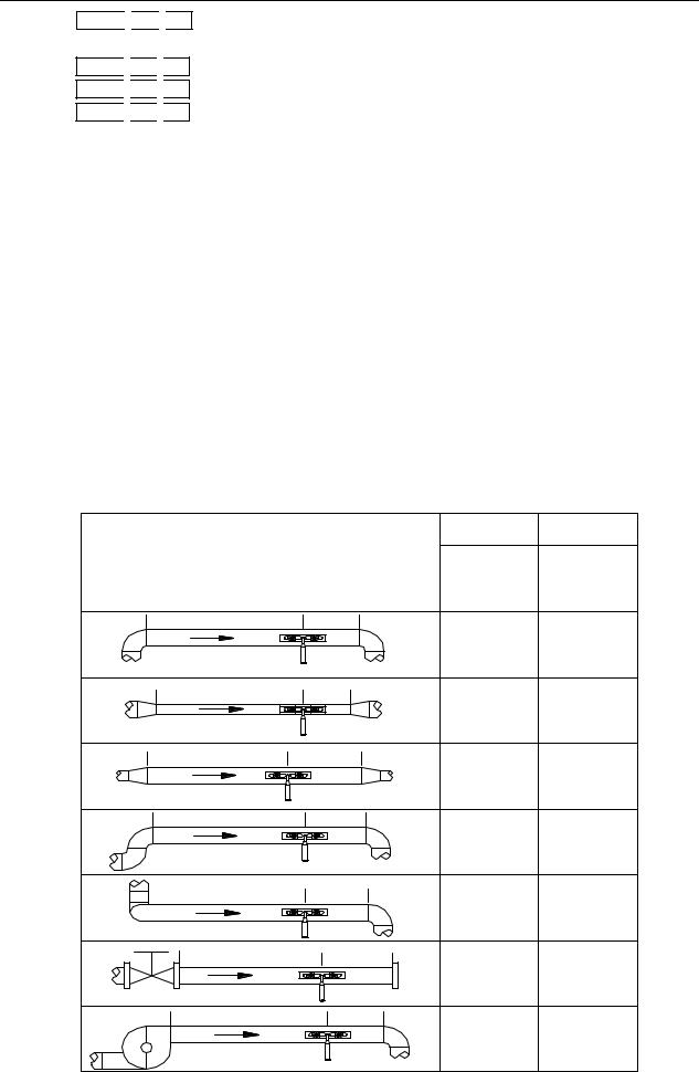
2.6 Transducers Mounting Allocation
The first step in the installation process is the selection of an optimum location in order to obtain a more accurate measurement. For this to be completed effectively, a basic knowledge about the piping and its plumbing system would be advisable.
An optimum location would be defined as a straight pipe length full of liquid that is to be measured. The piping can be in vertical or horizontal position. The following table shows:
Piping |
Configuration |
Upstream |
Downstream |
||
Dimension |
Dimension |
||||
|
and |
|
L up |
L dn |
|
Transducer |
Position |
||||
x Diam eters |
x Diam eters |
||||
|
L up |
L dn |
|
|
|
|
|
|
10D |
5D |
|
|
L up |
L dn |
|
|
|
|
|
|
10D |
5D |
|
|
L up |
L dn |
10D |
|
|
|
|
|
5D |
||
|
L up |
L dn |
|
|
|
|
|
|
12D |
5D |
|
|
L up |
L dn |
20D |
5D |
|
|
|
|
|||
|
L up |
L dn |
20D |
5D |
|
|
|
|
|||
|
L up |
L dn |
|
|
|
|
|
|
30D |
5D |
|
Loading...