


LIMITED LIFETIME WARRANTY
Products manufactured and sold by OMEGA RESEARCH & DEVELOPMENT, INC. (the Company), are warranted to be free from defects in materials and workmanship under normal use. If a product sold by the Company proves to be defective, the Company will repair or replace it free of charge within the first year and thereafter all parts to be repaired will be free with only a nominal charge for Omega Research and Development, Inc.'s labor and return shipping, to the original owner during the lifetime of the car in which it was originally installed.
All products for warranty repair must be sent postage prepaid to Omega Research & Development, Inc., P.O. Box 508, Douglasville, Georgia 30133, with bill of sale or other dated proof of purchase. This warranty is nontransferable and does not apply to any product damaged by accident, physical or electrical misuse or abuse, improper installation, alteration, any use contrary to its intended function, unauthorized service, fire, flood, lightning, or other acts of God.
This warranty limits the Company's liability to the repair or replacement of the product. The Company shall not be responsible for removal and/or reinstallation charges, damage to or theft of the vehicle or its contents, or any incidental or consequential damages caused by any failure or alleged failure of the product to function properly. Under No Circumstances Should This Warranty, Or The
Product Covered By It, Be Construed As A Guarantee Or Insurance Policy Against Loss. The Company neither assumes nor authorizes any person or organization to make any Warranties or assume any liability in connection with the sale, installation, or use of this product.
This device complies with part 15 of the FCC Rules. Operation is subject to the following two conditions: (1) This device may not cause harmful interference and, (2) This device must accept any interference received, including interference that may cause undesired operation.
The manufacturer is not responsible for any radio TV interference caused by unauthorized modifications to this equipment. Such modifications could void the user’s authority to operate the equipment.
One or more of these patents may apply to this product:
#5,612,669 #5,654,688 #5,663,704 #5,729,191 #5,818,329 #5,612,578 #5,739,747 #382,558 #385,878 #5,750,942 #5,739,748 #5,719,551 #406,107 #701,285 #5,973,592 #5,982,277 #5,986,571 #6,011,460 #6,037,859 #6,049,268 #6,130,605 #6,130,606 #6,140,938 #6,140,939 #6,150,926 #6,144,315 #6,184,780 #6,188,326 #6,243,004 #6,249,216 #6,275,147 #6,297,731 #6,320,514 #6,320,498 #6,346,876 #6,346,877 #6,366,198 #6,392,534 #6,429,768 #6,433,677 #6,480,095 #6,480,117 #6,480,098 Foreign Patent #199700312 #EP0817734B1 #98906445.6 #2,320,248 #701,285
09/04 MA_MARS/V1
OPERATING & INSTALLATION
INSTRUCTIONS
MARS-22
DELUXE KEYLESS ENTRY & REMOTE STARTER
FOR AUTOMATIC TRANSMISSION VEHICLES ONLY
COPYRIGHT: OMEGA RESEARCH & DEVELOPMENT 2004
2 |
Contents |
|
Operation Guide |
Introduction & Safety Considerations .......................................................................... |
3 |
Basic Transmitter Functions Overview ........................................................................ |
4 |
Remote Locking & Unlocking the Doors ...................................................................... |
5 |
Remote Starting the Engine |
6-7 |
Remote Panic & Emergency Flashlight ....................................................................... |
8 |
Remote Trunk Release ................................................................................................ |
9 |
Multiple Vehicle Operation ........................................................................................... |
9 |
The Receiver Unit ...................................................................................................... |
10 |
Programmable Features ....................................................................................... |
10-18 |
Programming Transmitters ................................................................................... |
18-19 |
Limited Lifetime Warranty ........................................................................... |
Back Cover |
|
Instructions |
Installation Considerations ................................................................................... |
22-23 |
Installation Cautions and Warnings ........................................................................... |
22 |
Main & Receiver Modules .......................................................................................... |
23 |
Wiring Diagram Overview ..................................................................................... |
20-21 |
6 Wire Main Harness ............................................................................................ |
24-26 |
3 Wire Connector .................................................................................................. |
26-27 |
12 Wire Harness ................................................................................................... |
27-34 |
2 Wire Connector .................................................................................................. |
34-39 |
Control
Module
Green
Wire
+
|
|
|
|
|
39 |
|
|
Blue Wire |
|
Reversing Polarity System |
|
+ |
|
|
+ |
Using External |
|
|
|
|
|||
85 |
|
|
|
85 |
Relays |
|
|
|
|
||
87 |
87a |
|
|
87 |
87a |
Coil |
|
|
|
Coil |
|
86 |
30 |
|
+ |
86 |
30 |
|
|
||||
Lock |
Lock |
Unlock |
Doorlock Actuators |
Unlock |
|
|
Secondary Doorlock |
||
Master Doorlock |
|
|
|
Switch |
+ |
+ |
Switch |
|
+ |
+ |
|

38 |
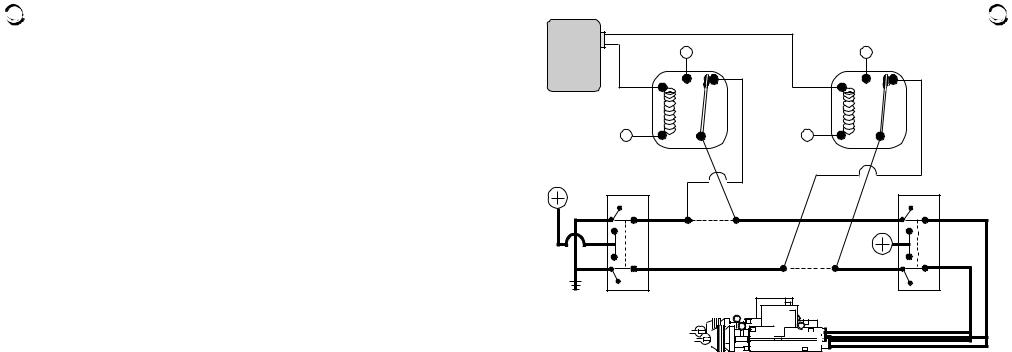
the wires show partial ground through the relay’s coils. |
2) The doorlock switch in a Reversing system will have 5 wires, while a Positive |
pulse system the switch will have 3 wires.
3) A Positive pulse system uses factory relays or a control unit, a Reversing system does not.
This power doorlock system differs from the negative and positive pulse systems in that there is no doorlock control unit or relays. In this type of system, the switches themselves supply the positive voltage directly to the doorlock actuators, and, more importantly, provide the return ground path. It is important to note that the lock and unlock wires in this system actually rest at chassis ground. This means that both the lock and unlock wires must be "opened", or cut, to make the proper connections.
Examine the wires on the back of the switch. (Normally 5 wires will be found
1)One wire will show +12 Volts, regardless of the switch's position.
2)Two wires will be grounded regardless of the switch's position.
3)One wire will show +12 Volts only when the switch is pushed to "Lock".
4)One wire will show +12 Volts only when the switch is pushed to "Unlock".
-When the lock /unlock wires are found, they must be cut one at a time. If the correct wires are cut the door locking system should not operate from the primary switch.
-Notice that in the diagram the driver's switch is the primary or “Master” switch (in some vehicles, the primary switch is on the passenger's side). The half of the cut wires which come from this primary switch are referred to as the "Switch" side. The half of the cut wires which go to the secondary switch are referred to as the "Motor" side even though the cut is made between the switches.
Introduction & Safety Considerations  3
3
Congratulations for choosing the Modular Advanced Remote Starter and Keyless Entry system. The MARS-22 offers the convenience of locking and unlocking your vehicle’s doors with the press of a button, and starting your vehicle's engine from the comfort of your home or office, allowing it to warm up in winter and cool down in summer. The MARS can also be configured to remotely open your vehicle’s trunk.
It is highly recommended that this system be professionally installed, as the sophistication of the modern automobile and the complexity of this type of product installation is often beyond the abilities of most do-it-yourselfers.
There are several important safety considerations with using and installing the MARS keyless entry and remote starter. Among them are:
This unit is for vehicles with an automatic transmission only. Installation in a vehicle equipped with a manual transmission can result in property damage or personal injury.
This unit is for fuel injected gasoline or diesel engines.
Children should not be left unattended in, or be allowed to play with the activating transmitters of any remote starter equipped vehicle.
Do not use the remote starter feature in an enclosed garage or other structure.
The MARS is a very flexible system. It has capabilities, such as sounding the horn, which may or may not be utilized in your installation. It also has many programmable features which can affect its operation. While these are explained as thoroughly as possible in this guide, your Omega dealer or installer is the best source for information about your system.

4 |
Basic Transmitter |
Functions |
||
The MARS includes with two 5-button remote transmitters.* |
The control buttons’ o p e r a - |
|||
tions are shown here, and are described in more |
|
• Cool Blue LED light |
||
in the following pages. |
|
|
||
|
|
lights when transmitting, |
||
|
|
|
|
|
Upper button |
|
|
and can be used as an |
|
with “START” |
• |
|
|
Emergency light by the |
|
|
• button with the |
||
activates the remote |
|
|
||
|
|
“LIGHT” icon , |
||
engine start feature |
|
|
||
|
|
which lights the LED |
||
|
|
|
|
|
Left button |
|
|
|
brighter without |
|
• |
|
transmitting |
|
with “LOCK” icon |
|
Right button |
||
locks the doors, and |
|
• |
||
also activates the |
|
with “UNLOCK” icon |
||
“panic” feature |
|
|
|
unlocks the doors, and also |
|
|
|
activates the “panic” feature |
|
* The transmitter also has a |
Lower button |
|||
“multi-car” switch |
on its |
• with “OPEN TRUNK” icon |
||
side; see page 9. |
|
|||
|
operates the trunk release feature |
|||
|
|
|
||
3) One wire will show +12 Volts only when the switch is pushed to "unlock". |
37 |
|
|
2-Wire Connector Positive Pulse System Using External Relays |
|
Control
Module
Green
Wire
+
Doorlock
Switch
+
+ |
Blue Wire |
|
+ |
Doorlock |
|
|
|
|
|||
|
|
|
|
||
85 |
|
|
85 |
Actuators |
|
|
|
|
|||
87 |
87a |
|
87 |
87a |
|
Coil |
|
|
Coil |
|
|
|
|
+ |
|
+ |
|
86 |
30 |
86 |
30 |
||
|
|||||
|
|
|
Vehicle's Doorlock |
||
|
|
|
Relay Control Unit |
||
|
|
Unlock |
|
||
|
|
Lock |
|
||
Warning: The Positive pulse system can be confused with the 5-wire Reversing Polarity system. This is because both systems show +12 Volt pulses on the “Lock” and “Unlock” wires when the vehicle’s switch is pressed respectively. It is critical to identify which system is present, since if +12 Volts is pulsed into a Reversing Polarity system, which rests at ground, a direct short circuit will occur.
3 main differences between a Positive pulse and a Reversing Polarity system:
1) In a Reversing system the Lock/Unlock wires rest at ground, while in a Positive system
36 |
operate the vehicle’s on-board doorlocking relays. |
If the vehicle’s Negative pulse |
||
|
doorlocking system requires more than 500mA Negative output, optional relays must |
|||
|
be used. |
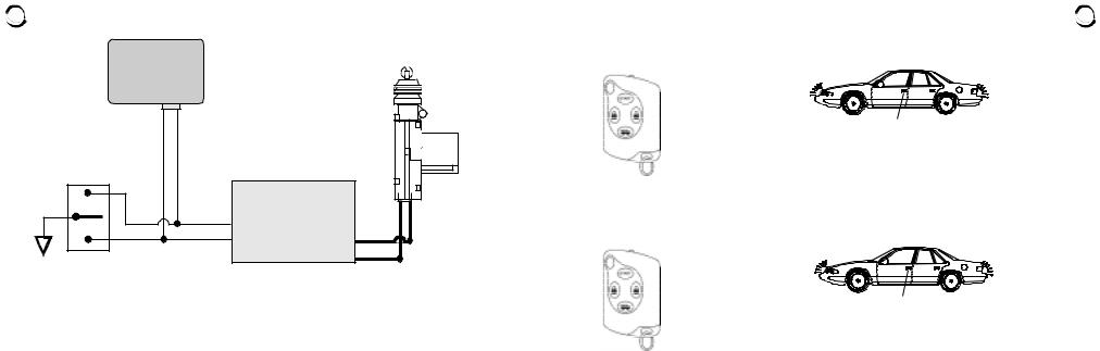
Negative Pulse System Using |
||
|
|
Control |
||
|
|
Direct Connection |
||
|
|
Module |
|
|
|
|
|
2-Wire Connector |
+ |
|
Green Wire To Switch |
Blue Wire To Switch |
|
|
|
|
Door Lock Wire |
Door Unlock Wire |
|
|
|
|
Vehicle's Doorlock |
Doorlock |
|
|
|
Actuators |
|
|
|
|
Relay Control Unit |
|
|
|
|
|
|
|
|
|
Unlock |
|
|
|
Door Lock |
Lock |
|
|
Ground |
|
|
|
|
Switch |
|
|
|
3 Wire Positive Pulse Systems
This doorlock system is similar to the 3 wire negative pulse system except the doorlock switches send +12 Volt pulses to operate the doorlock relays/control unit.
Examine the wires on the back of the doorlock switch:
1)One wire will show +12 Volts, regardless of the switch's position.
2)One wire will show +12 Volts only when the switch is pushed to "lock".
Locking & Unlocking the Doors |
5 |
To Lock the Vehicle's Doors: Press & Release the left transmitter LOCK button
|
THE PARKING |
* |
LIGHTS WILL FLASH |
ONCE |
|
THE DOORS WILL LOCK |
•The parking lights flash once to confirm locking, and optionally, the horn will chirp once. The Status Light on the Receiver Unit will have one long flash when a lock signal is received.
To Unlock the Vehicle's Doors: Press & Release the right transmitter UNLOCK button
|
THE PARKING |
* |
LIGHTS WILL FLASH |
TWICE |
|
THE DOORS WILL UNLOCK |
|
• The parking lights flash twice then stay on for 30 seconds to confirm |
unlocking, and optionally the horn will chirp twice. The Status Light on the Receiver Unit will have two long flashes when an unlock signal is received.
The MARS is equipped with a horn/siren output; its connection is optional and may require extra parts.

6 |
Remote Starting |
* |
To Activate Remote Start: Press & Release the upper |
transmitter START button |
|
THE PARKING LIGHTS |
|
WILL TURN ON, OFF, THE |
|
ENGINE STARTS, THEN |
|
THE PARKING LIGHTS |
|
|
RESUME BEING ON |
•The parking lights will turn on and the Status Light will flash to confirm the starting process (and, optionally, the horn will also chirp 3 times).
•The ignition circuit will turn on.
•Within a few seconds the parking lights will turn off and the starter will engage.
•The engine will start, run, and the starter will be disengaged.
•The parking lights will turn back on and remain on while the MARS is controlling the engine. The status light will pause, and then continue to flash slowly.
•If the engine stalls, the MARS will make two attempts to restart it.
When you leave your vehicle, simply set the climate controls for what you would like to have operating upon remote starting - the heater, defroster or air conditioning.
Upon entering the vehicle place the ignition key in the switch and turn it to the "On" position, and then deactivate the MARS. Do not turn the key to the "Start" position!
22 Gauge Blue Wire: 500mA ( - ) Unlock Output 35
Connection If Desired. The Blue wire supplies a negative pulse for locking the vehicle's doors. Programmable feature #12 changes the single unlock pulse to be a double unlock pulse.
This harness, which plugs into the White 3-pin port on the control module, is the power doorlock outputs by which the MARS operates the vehicle’s power doorlock system (the vehicle must have existing power doorlocks). The doorlock interface needed to allow the system to operate the doorlocks will depend upon the type of power doorlocking system the vehicle is equipped with. The following sections describe typical power doorlocking systems, which are categorized as “3 Wire Negative Pulse”; “3 Wire Positive Pulse”, and “5 Wire Reversing Polarity” systems.
3 Wire Negative Pulse Systems
This power doorlock system is simplest of all doorlocking systems. A Negative pulse system will have only three wires at the doorlock switch.
Examine the wires on the back of the doorlock switch:
1)One wire will show Ground, regardless of the switch's position.
2)One wire will show Ground only when the switch is pushed to "Lock".
3)One wire will show Ground only when the switch is pushed to "Unlock".
The lock & unlock wires coming out of the switch operate the vehicle’s doorlock relays or a control unit with on-board relays, therefore the lock & unlock wires will read Positive voltage, up to +12 Volts, when the switch is at rest. The correct connection point is between the switches and the relays. The Red connector's Green and Blue wires can be connected directly to the vehicle’s Negative pulse system since only a Negative pulse is required to
 Loading...